1. Introduction
Nowadays, synchronous machines with rare-earth magnets in the rotor (PMSM) are widely used in electric vehicles as they have low weight, small size, and high efficiency [
1,
2]. PMSMs have good specific characteristics for traction drives that require a narrow constant power speed control range (CPSR), typically no more than 4:1 [
2,
3]. However, such permanent magnet synchronous machines have the following disadvantages:
Use of high-cost permanent magnets;
Large value of uncontrolled electromotive force (EMF) at the terminals during rotation of the rotor, which increases the risk of fire in the event of an emergency short-circuit;
Since rare-earth magnets are used in the production of PMSMs, there is a technological dependence on a limited number of suppliers of rare-earth elements [
4]. Prices for rare-earth elements are volatile and can change very significantly over the course of several years [
5,
6];
The extraction of rare-earth elements necessary for the production of rare-earth magnets causes great harm to the environment [
7];
Traction motors during operation heat up above 120 °C. This can result in irreversible deterioration of properties of the rare-earth magnets: the residual flux density and coercive force decrease and the risk of demagnetization increases;
Since magnetomotive force (MMF) of permanent magnets cannot be controlled, in case of a large constant power speed range, PMSMs will have high winding losses and heating at the upper speed limit because of the additional winding current weakening the field [
8,
9,
10].
The disadvantages of rare-earth permanent magnet synchronous machines noted above prevent their use in traction drives of subway trains, railway trains, trams, mining dump trucks, etc.
In order to overcome the disadvantages of PMSMs, leading manufacturers, such as Audi, BMW, and Renault, have developed magnet-free motors. Audi used a squirrel case induction motor in its e-tron. The DC-excited wound rotor synchronous motors (hereinafter referred to as “wound rotor synchronous motor”, WRSM) were developed for BMW and Renault electric vehicles (BMW iX3, Renault Zoe, Renault Fluence, Renault Megane E-TECH car models) [
11,
12,
13]. The required inverter power can be reduced for WRSM by using flux weakening through controlling the rotor excitation current [
14,
15,
16]. However, in BMW iX3 and Renault Zoe electric vehicles, a sliding contact (slip rings) is used to supply the excitation winding on the rotor, which reduces the reliability of the motors [
16].
An alternative can be highly reliable brushless synchronous homopolar machines (SHM) with an excitation winding on the stator and a passive salient pole rotor. SHMs are usually used in applications where high reliability is required: in welding units [
17], in automotive, passenger railway cars, shipboard, and aircraft generators [
18,
19,
20]. Other papers [
21,
22,
23] describe the application of the SHM as a traction motor.
The main advantages of SHMs in comparison to WRSMs are the elimination of the sliding contact that feeds the excitation winding or wireless exciter, high reliability, and the effective excitation not requiring an increase in the number of excitation coils with an increase in the number of poles, whereas, in WRSMs, every rotor tooth is wound with an excitation coil.
There are synchronous machines with an excitation winding on the rotor that is fed from a brushless exciter (hereinafter WRSM with a brushless exciter) [
24,
25]. Such machines are most often used as generators [
24]. In recent years, WRSMs with a brushless exciter have also been introduced for electric vehicles [
16,
25,
26]. In such a WRSM, a rotating transformer is used as a brushless exciter, the primary winding of which is placed on the stator, and the secondary winding and the diode rectifier are placed on the rotor [
16]. However, WRSMs with a brushless exciter are currently not widely used in electric vehicles because of their disadvantages compared with a brushed WRSM, including an increase in cost and design complexity due to the use of a brushless exciter [
27].
Many articles have focused on optimizing WRSMs and comparing WRSMs to other types of traction motors. For example, in Ref. [
28], the WRSM is compared to the PMSM in an electric vehicle with a CPSR of 2:1. In Ref. [
29], the WRSM is compared to the PMSM in traction application considering only one operating point (rated rotational speed). In Ref. [
30], a comparison of various motor types, including a WRSM, PMSM, and induction motor for traction applications with CPSR = 3.5:1, is presented.
Such small values of CPSR are specific to electric cars when the demands to the traction properties have lower priority than the price of the vehicle. However, even gasoline cars with a mechanical gearbox have from five to seven gears, which is approximately equal to CPSR from ~4 to ~6 as well.
For mining trucks, the traction drive must meet additional specific requirements. On the one hand, a loaded dump truck must carry the full weight with a given incline. On the other hand, it must move as fast as possible with a diesel-generator of limited power on board. The best performance (weight of the payload: ore, coal, etc.) can only be achieved during continuous operation at the maximum diesel-generator power for hours at speeds from 6 to 60 km/h, which is equal to a CPSR of 10:1. Since the width of the CPSR, other things being equal, also depends on the type of electrical machine, the question arises as to which type of electrical machine can provide the best performance in a drive with such a wide CPSR.
In a previous paper [
9], the authors presented a comparison of the performance of the SHM and PMSM in the application under consideration. It has been shown that the PMSM may not be practical for wide CPSR applications due to high loss and heating at high rotational speeds.
In continuation of comparing different types of electrical machines in the target application, this paper compares the performance of an SHM and WRSM for a hybrid mining dump truck application requiring a wide speed range from 400 to 4000 rpm at a constant mechanical power output of 370 kW (CPSR 10:1).
A comparison of the active materials cost of electrical machines and the cost of power inverter modules for the SHM and WRSM is also presented. The scientific novelty of the article lies in the comparison of the characteristics of the SHM and WRSM in a traction application with a wide CPSR of 10:1, which was not previously considered in the literature. The calculated characteristics of the WRSM are compared with the SHM characteristics obtained in the previous study. To ensure objective results, both motors’ designs were optimized using a similar optimization procedure.
2. Design Features of the Considered Motors
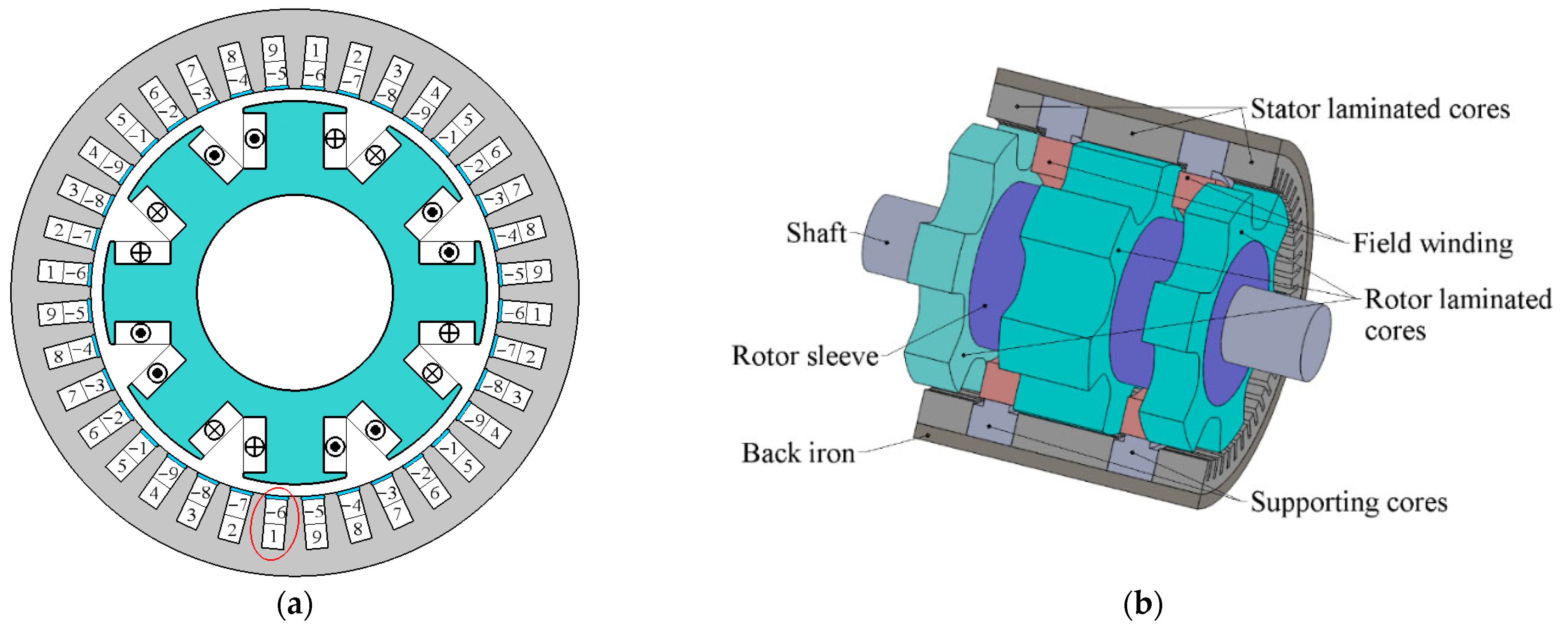
Figure 1a shows the design of the conventional WRSM in only one plane since it is well-known and uniform along the axis of rotation [
31].
Figure 1b shows a three-dimensional sketch of the SHM design since this type of motor has three laminated rotor and stator stacks with gaps between them, having an angular shift between adjacent rotor stacks.
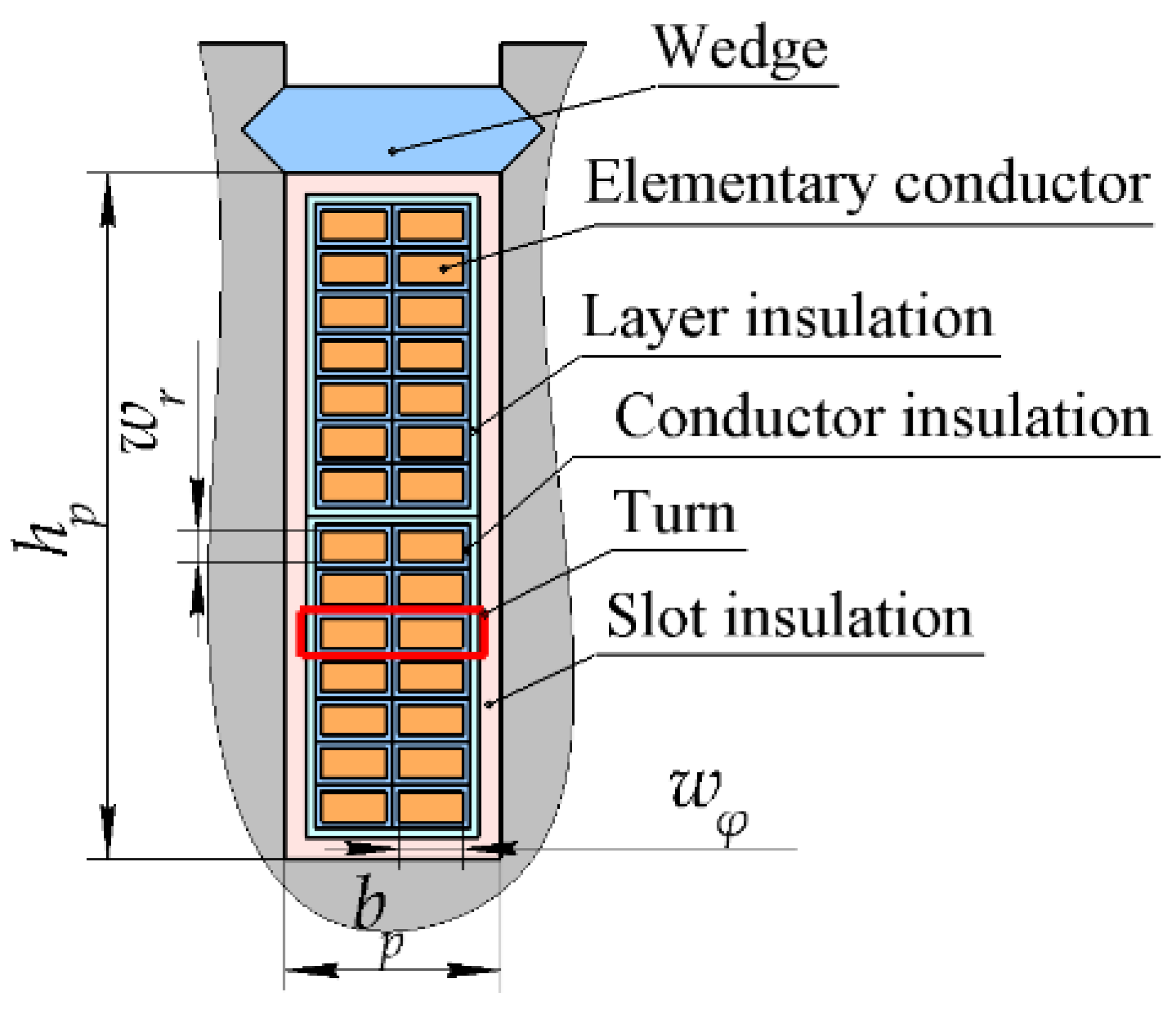
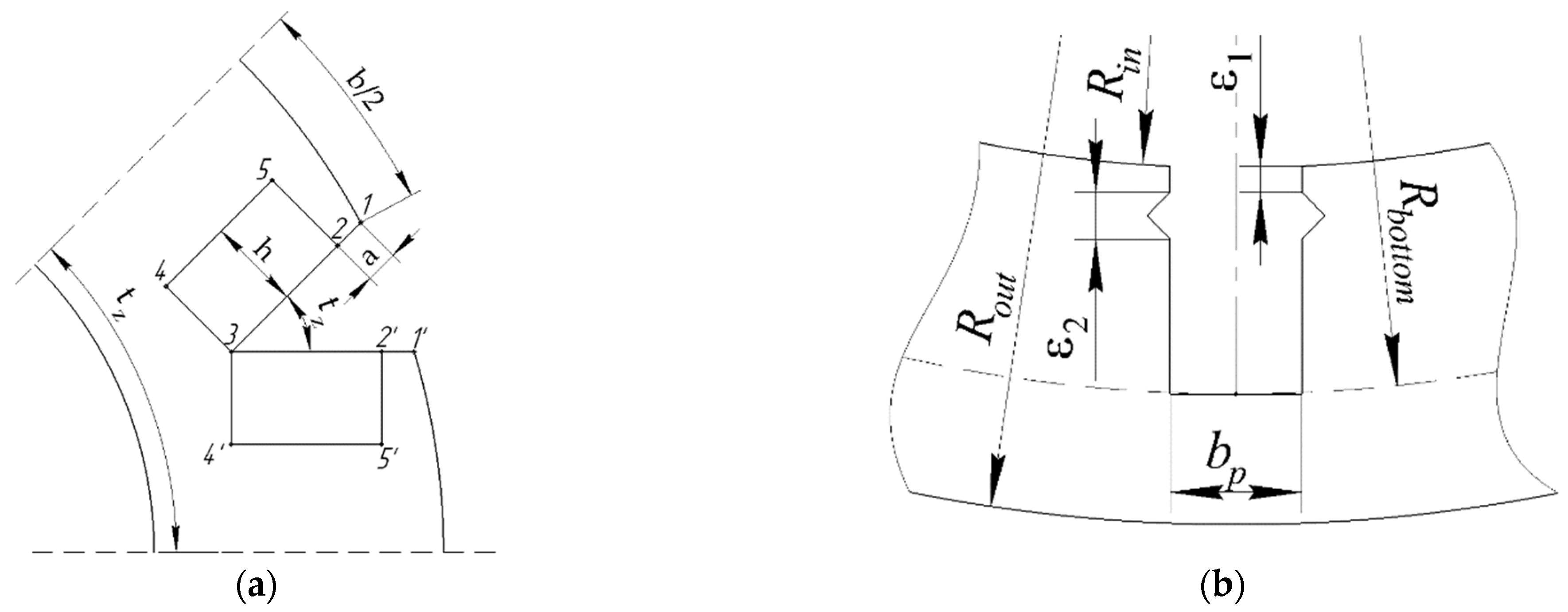
Figure 2 shows the open type stator slot sketch that is relevant for both motors.
Both considered electrical machines have a 9-phase two-layer winding. Since the increase in the number of poles in the SHM does not require an increase in the number of field coils, the number of poles in the SHM is quite large and equal to 12. To increase the area of each field coil (pole pitch) in the WRSM, the number of poles is reduced to 8. The WRSM stator has 36 teeth. The SHM stator has 54 teeth.
In
Figure 1a and
Figure 3, the numbers from 0 to 8 indicate the order of the motor phases. The minus sign in
Figure 1a indicates the reverse direction of the current in a winding layer. The SHM has the number of teeth per pole and per phase equal to 54/(9 × 12) = 0.5. Although the WRSM has a different number of slots and poles, the number of slots per pole and per phase is also 36/(9∙× 8) = 0.5.
An 8-pole excitation winding is wound on the WRSM rotor. The WRSM rotor is salient-pole and has semi-closed slots with long and narrow tooth protrusions (
Figure 1a). The laminated part of the magnetic core of the SHM is divided into 3 stacks on the rotor and 3 stacks on the stator, with different angular orientation of the rotor stacks. Adjacent rotor stacks are offset by 30 mechanical degrees. Each rotor stack is passive and has 6 salient poles of the same polarity; another polarity is missed. In each of 2 gaps between the core stacks, a coil of the excitation winding is placed.
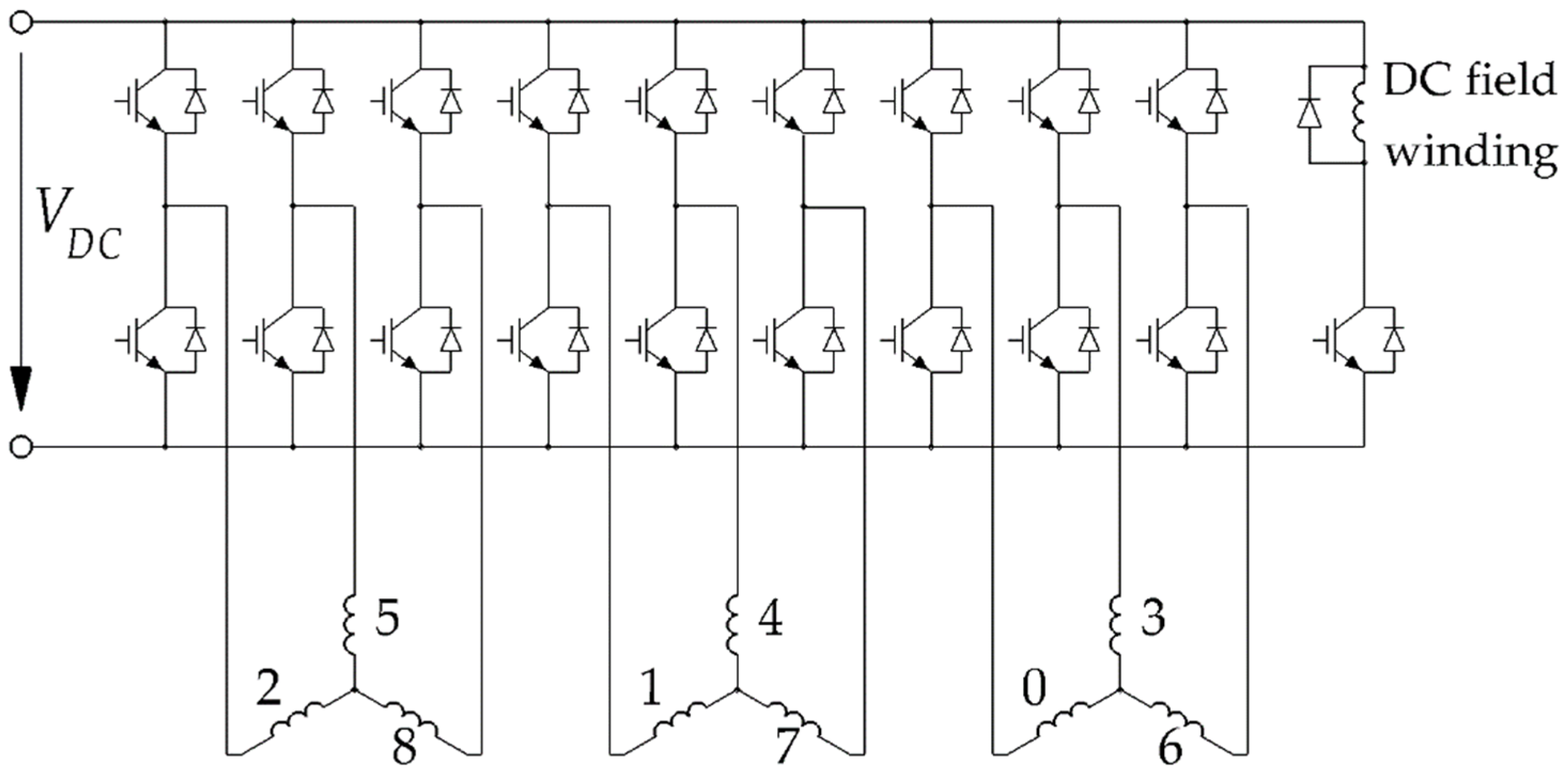
The motors in question are powered by a nine-phase inverter, the circuit of which is shown in
Figure 3. The nine-phase inverter is assembled from three separate three-phase modules, each of which feeds three phases of the motor. In addition, the inverter includes a DC breaker that feeds the motor excitation winding. The maximum amplitude of line-to-line voltage of 1000 V is limited by the voltage in the DC link. One microcontroller unit with 18 synchronous pulse-width modulation signals provides inverter switching. For each of the three-phase modules, discontinuous space-vector modulation is used [
32].
The use of a nine-phase inverter, in comparison with a three-phase one, makes it possible to reduce the current rating of individual power modules. In addition, it provides better reliability in case of failure of individual power modules. The use of a nine-phase winding in the motor makes it possible to increase the winding factor and improve the spectral composition of the magnetomotive force.
The parameters, objectives, and results of the optimization of the SHM are described in detail in Ref. [
23]; therefore, in this article, we present only the final results of the optimization of the SHM in
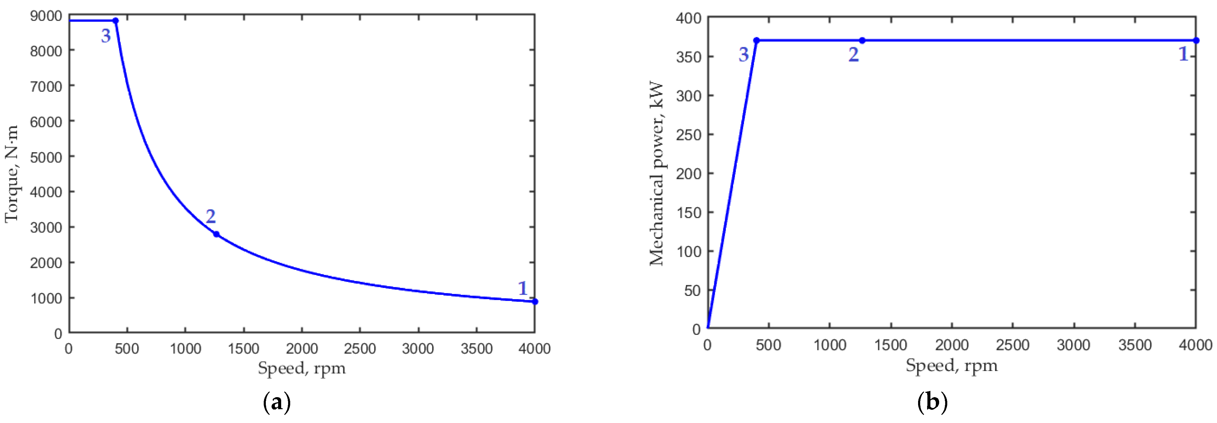
Section 5. The compared motors must meet the requirements for the traction characteristic of the BELAZ 75570 mining truck drive, shown in
Figure 4. The drive must provide an output mechanical power of 370 kW in the speed range from 400 rpm to 4000 rpm (10:1).
3. Some Details on WRSM Mathematical Model
When designing traction electric machines with a rectangular wire winding, one inevitably has to deal with the limitation of the supply voltage, a small number of turns per coil, and, as a result, the effect of substantial discreteness in the choice of the number of turns. The range of standard wire cross-sections is also discrete. However, if it is required to evaluate characteristics of the machine for an application characterized by a similar power rating, CPSR, dimensions, etc., the number of turns can be taken as a fractional number. One can make such an assumption in preliminary optimization, first, because, for the optimal design of the motor, the number of turns may be closer or further to the nearest integer, and, second, the cross-section of the wire may be more or less close to a standard one. Therefore, the above discrete factors are unpredictable, pseudo-random. Second, the deviation in the characteristics of the machine from the optimum when changing the parameters due to the consideration of discreteness is usually not large since, in the extremum point, the derivative of the objective function with respect to the optimized parameters is zero. Therefore, it can be expected that, in the final design, taking into account the discreteness of the above factors, the predicted characteristics of the machine will change only slightly compared to the design optimized when these factors are considered continuous. For this reason, in the frame of this comparative study, the number of turns per coil is assumed to be fractional, and wire sizes may not correspond to the standard range.
A small number of turns per coil, typical for traction applications, leads to an increase in the conductor cross-section and, as a result, to an increase in additional loss in the winding due to eddy currents caused by the crossing of the conductors by parasitic slot leakage magnetic flux and by flux penetration into the slot. The width and height of the rectangular wire are calculated based on the dimensions of the slot, the thickness of the liner, the thickness of the layer and conductor insulation, and the number of turns. A fractional number of turns per coil can also be adopted in this calculation. The density of the additional eddy current loss in the winding is calculated by the formula:
where
σCu is the electrical conductivity of copper;
wφ and
wr are the width and height of the wire section;
kz is the slot filling factor;
Br and
Bφ are the radial and tangential components of the flux density. Thus, the additional loss density can also be calculated for a fractional number of turns per coil.
Figure 2 shows the structure of the WRSM stator slot. The relationship between the dimensions of the slot, the number of turns, and the dimensions of the wire are the same as in Ref. [
9]. Each turn is represented by two elementary conductors laid along the slot, which reduces the eddy current losses from the penetration of the flux into the slot due to a 2-fold reduction in the width of the conductor
wφ.
In the considered mathematical model, the input variables that define electromagnetic processes in operating points 1, 2, and 3 (see
Figure 4) are the armature control current angles and the flux of the excitation winding. The additional degrees of freedom to satisfy the required torque and the voltage restriction are the armature current amplitude at operating points 1, 2, and 3 and the number of turns. These values are chosen to obtain the required torque at operating points 1, 2, and 3 and to obtain the maximum peak line-to-line voltage (achieved at operating point 1) equal to the DC link voltage.
4. Parameters and Objectives of the WRSM Optimization
A substitute profile with a small discrete number of operating points is used to analyze motor performance in the driving cycle and to significantly reduce the analysis time.
Figure 3 and
Table 1 show the substitute profile points 1, 2 and 3 chosen to analyze the performance of the motor in the drive cycle.
Operating point 1 at a speed of 4000 rpm is characterized by the minimum torque and the maximum electric frequency of the fundamental current component, the maximum losses in steel, and additional losses in the winding due to eddy currents. Operating point 3 at a speed of 400 rpm is characterized by the minimum fundamental electrical frequency and the maximum copper loss and armature current. Motor performances are often evaluated only at points 1 and 3, which are on the border of the considered speed range since they can be used to approximate motor performance over the entire speed range in the field weakening region [
33].
In the case of the large CPSR of 10:1, the introduction of the intermediate point 2 with average geometric torque and speed is necessary to increase the accuracy of the analysis of integral parameters, for example, average losses in the driving cycle, taking into account that the considered traction drive most of the time does not run near the boundary points 1 and 3 but in the inner part of the considered speed range. Based on the assumptions that the motor operates with equal probability in subranges 1–2 and 2–3, and also that the average losses in the subranges are equal to the arithmetic average of the losses at their boundaries (points 1 and 2 and points 2 and 3, respectively), we use the following expression to determine the average loss in a driving cycle:
The other objectives are maximum torque ripple max(TR) and current max(I) for these three operational points 1, 2, 3.
In this study, the single-criterion Nelder–Mead method is used for optimization. The Nelder–Mead algorithm used for optimization is well-known [
34] and is included in the basic MATLAB software package (function “fminsearch”). The objective function has the form:
Figure 5 shows the geometric parameters of the WRSM. The following describes the procedure for constructing the WRSM rotor geometry. Point 1 is located at an angular distance b/2 from the boundary of the tooth pitch. The boundary of the tooth pitch is shown with the dotted line. Straight lines 123 and 1’2’3 are parallel to the boundary of the tooth pitch. Point 3 is defined as the intersection of lines 123 and 1’2’3. Lines 25, 34 are perpendicular to line 123.
The fixed parameters and varied ones during the optimization are shown in
Table 2 and
Table 3. The value of rotor teeth thickness
b is given in rotor tooth pitches
tz = 45°.
5. Comparison of the WRSM Characteristics before and after the Optimization
This section compares and analyzes the results of the Nelder–Mead optimization of the WRSM performance using the optimization parameters and objective function described in the previous section.
Table 4 compares the characteristics of the WRSM before and after the optimization.
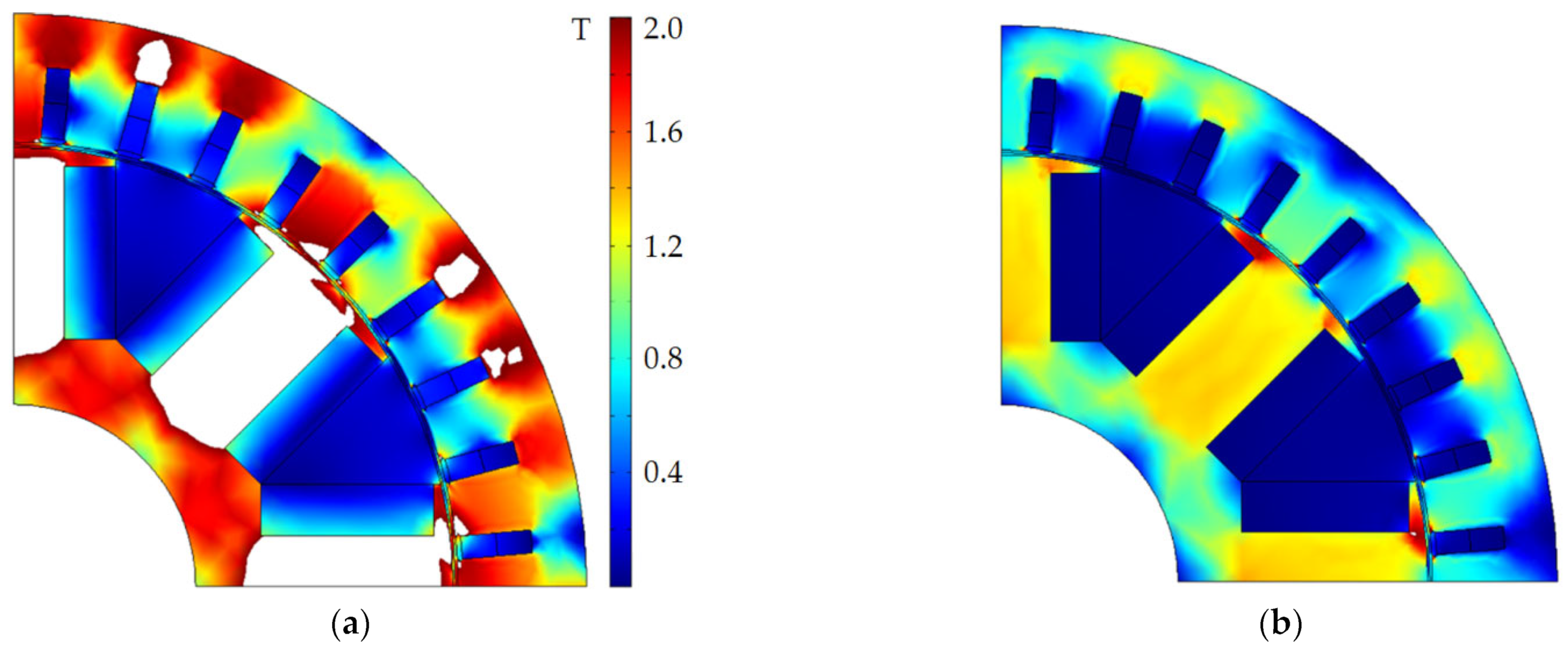
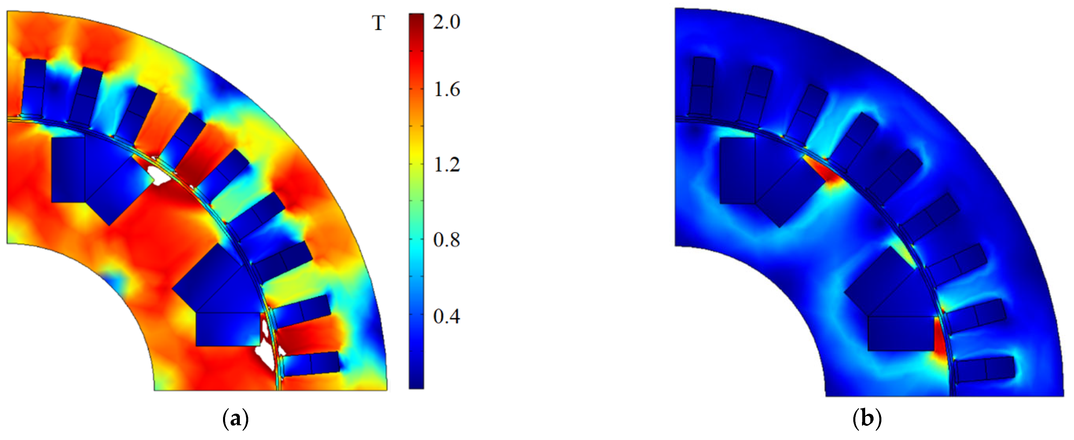
Figure 6 and
Figure 7 show the results of the flux density magnitude calculations for the WRSM at the first and third operating points (4000 and 400 rpm, correspondingly) before and after the optimization. It can be observed that, due to optimization, the area of regions with flux density >2 T has almost disappeared.
where
Vmax is the maximum value of
Va at operating point 1;
Imax is the maximum value of
Ia at operating point 3.
6. Comparison of the Characteristics of the Optimized SHM and WRSM
This section discusses the comparison of the characteristics of the considered electrical machines after optimization.
Table 5 shows a performance comparison between the optimized designs of the WRSM and the SHM.
Table 5 compares the performance of the optimized WRSM and SHM. The WRSM characteristics in
Table 5 correspond to the optimized characteristics from
Table 4 obtained in this study. The design methods and detailed results of the SHM optimization are described in the article [
23]. In order not to repeat ourselves, in
Table 5, we present only the final characteristics of the optimized SHM.
Upon calculating the efficiency, it was assumed that the losses in the wireless exciter are 10% of DC winding losses. Another assumption is the equality of bearing losses and ventilation losses for compared motors.
Table 6 shows a comparison of the dimensions, masses, and costs of active materials for the compared motors.
Comparing the characteristics of SHM and WRSM, shown in
Table 5 and
Table 6, the following conclusions can be drawn:
The length of the WRSM stator, including the winding end parts, is 711/579 = 1.23 times less than the length of the SHM stator;
Average losses according to (1) for SHM are larger by 27.4/22.7 = 1.21 than for WRSM. This can be explained by poorer utilization of the rotor surface in the SHM;
The mass of active materials of the WRSM is (690.5−639)/639 = 8% more than that for the SHM. In addition, the WRSM requires a brushless exciter. However, modern brushless exciters for traction WRSMs are high-frequency ones and have a small mass [
27]. For this reason, a significant increase in the mass of the WRSM due to the use of the brushless exciter is not expected;
The SHM excitation winding is made up of two ring-shaped coils [
23]. By modulating the flux by the passive salient pole rotor, this winding creates a 12-pole rotating magnetic field that interacts with the armature winding. To increase the number of poles of the SHM, it is not necessary to increase the number of excitation coils, reduce their pitch, and increase their volume and mass. On the contrary, for efficient excitation of the WRSM, the number of poles is reduced to 8. Moreover, for the excitation winding of the WRSM, almost 63.1/20 = 3.155 times more copper is needed, which makes it possible to reduce the excitation copper loss for the SHM. The eddy current loss in the SHM is slightly higher than in the WRSM. The total cost of active materials for the WRSM is 1488/1167 = 1.27 times greater than for the SHM, mainly due to the larger quantity of copper in the excitation winding. Given that the WRSM additionally requires a brushless exciter, the cost of the WRSM will be significantly higher than that of the SHM;
In the SHM salient pole rotor, there are only losses in the steel caused by higher harmonics of the magnetic flux, which are (12.02 + 0.04)/0.1 = 120 times less than the copper loss in the rotor of the WRSM at operating point 3. Although the SHM rotor loss is only (2.41 + 0.51)/1.5 = 2 times less at operating point 1, the fast rotation of the salient pole rotor intensifies heat transfer. Therefore, the heating of the SHM rotor is much less than that of the WRSM rotor in all operating conditions. This advantage is especially important for liquid-cooled machines since SHM does not require a complex cooling system of the rotor;
The extremely simple and reliable SHM passive salient pole rotor made of electrical steel sheets does not have an excitation winding and a diode rectifier (unlike the WRSM with a brushless exciter) since its excitation winding is located on the stator. Thus, the SHM is simpler and more reliable than the WRSM with a brushless exciter.
7. Selecting the Inverter for the SHM and WRSM
For a given DC link voltage, the choice of inverter power modules is based on the maximum current consumed by the motor. The motor consumes the maximum operating current at operating point 3 (maximum torque). The rated current of the inverter power module must be chosen with a margin to take into account possible inaccuracies in the theoretical characteristics and the required output power shown in
Figure 4. As shown in
Table 5, the maximum instantaneous phase current is 292 A for the WRSM and 601 A for the SHM. Based on this, the following power modules with a current margin were selected from the catalog [
36]: FF650R17IE4 for the WRSM (maximum current 650 A, margin (650−292)/650 = 55%)) and FF1000R17IE4 for the SHM (maximum current 1000 A, margin (1000−601)/1000 = 40%)).
The authors of this article suggest that, to compare electric drives with different types of motors, it is instructive to evaluate their inverter utilization factor (hereinafter
Ki). The inverter utilization factor is the ratio of the output mechanical power to the rated apparent power of the inverter for the required CPSR of the traction drive (10:1 for the case under consideration):
The rated apparent power of the inverter is determined as follows:
where
m is the number of machine phases;
Imax is the maximum invertor output RMS current;
Vmax is the maximum output phase invertor RMS voltage;
VDC is the maximum (rated) DC link voltage of the inverter according to the technical specification of the IGBT module;
IC_nom is the maximum (rated) continuous inverter transistor current (collector current of the DC link) according to the technical specification of the IGBT module [
36].
Therefore, for the SHM with the inverter employing FF1000R17IE4 IGBT modules (VDC = 1000 V, IC_nom = 1000 A), according to (5) and (6), the inverter rated power is S = (9∙× 1000∙× 1000)/(2 √3) = 2589 kVA, and the inverter utilization factor Ki = 370/2589 = 0.142.
For the WRSM with the inverter employing FF650R17IE4 IGBT modules (VDC = 1000 V, IC_nom = 650 A), the inverter rated power is S = (9∙× 1100∙× 650)/(2∙√3)= 1689 kVA, and the inverter utilization factor is Ki = 370/1689 = 0.219.
The inverter utilization factor for traction applications may be more informative than the motor power factor. As can be seen from
Table 5, both the SHM and WRSM have a high power factor, and there is practically no difference in power factor between them.
The inverter utilization factor shows the efficiency of operation in field weakening mode with constant output power.
Based on the results of calculating the characteristics of the motors shown in
Table 5, and the technical specification of the selected power inverter modules, the losses and temperatures of the power switches were also calculated using the Infineon IPOSIM software [
37].
The fundamental frequency of the motor is according to the formula:
where
n is the rotational speed, rpm; p is the pole pair number.
The PWM (pulse width modulation) frequency is selected in proportion to the fundamental frequency based on an empirical relationship:
The modulation type “Space Vector Modulation (Standard)” was selected for calculations. The modulation index is calculated as:
where
Va is the fundamental line-line voltage amplitude;
VDC is the DC-link voltage.
Table 7 shows a comparison of the loss and temperature of the inverter switching elements when using both motors at operating point 3 (lowest fundamental frequency, highest current).
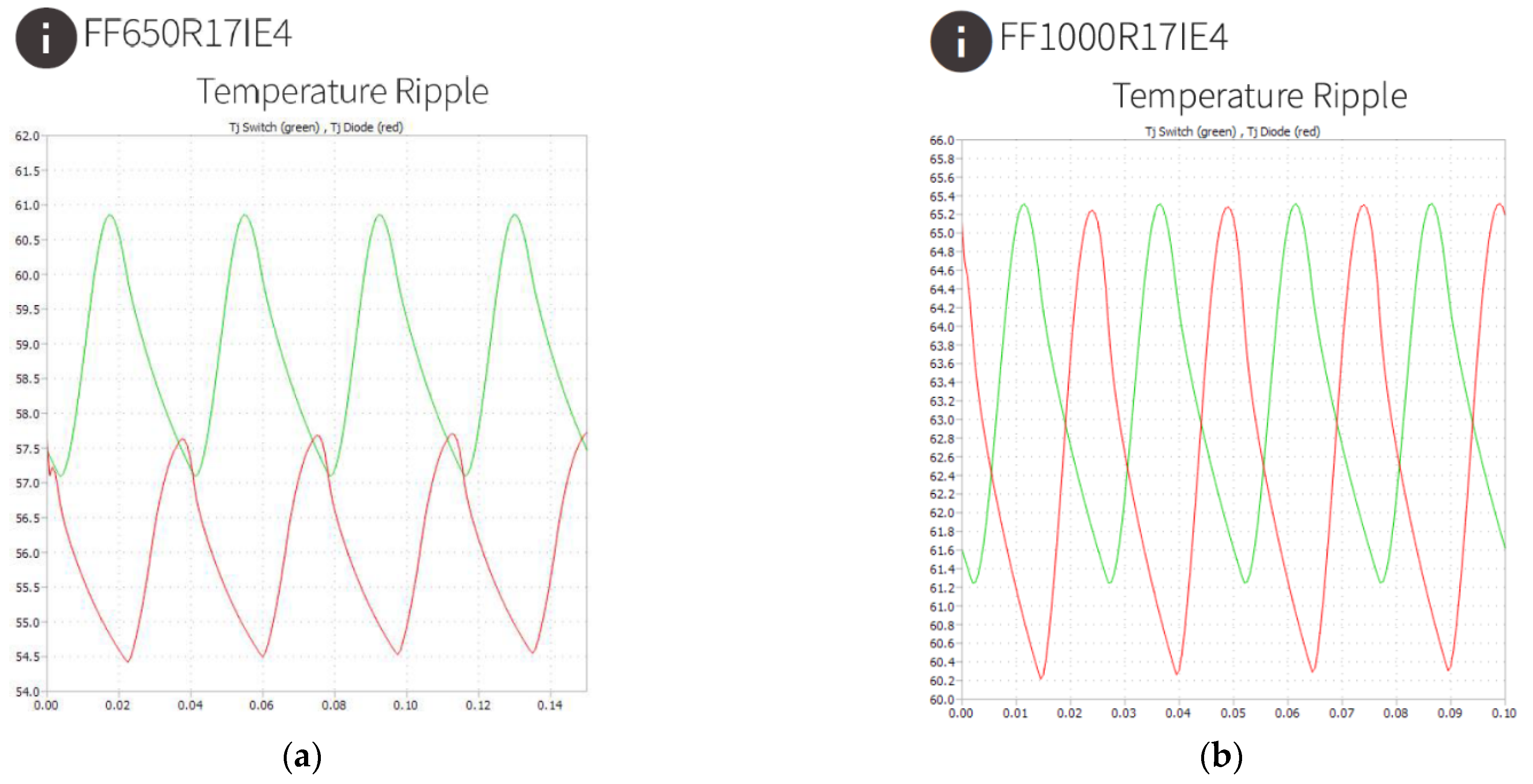
Figure 8 shows a comparison of the calculated temperature plots for the same case.
It can be seen that, in both cases, the temperature of the IGBT and the reverse diode change periodically in time with a sufficiently large amplitude, which has a negative impact on the lifetime of the power modules. In the case of the WRSM, the amplitude of the temperature ripple is smaller. In the case of the SHM, the frequency of the temperature ripple is higher due to the higher fundamental frequency. The maximum temperature of the inverter elements in the case of the WRSM is much lower, by 65.3 − 60.9 = 4.4 degrees, for the IGBT and by 7.6 degrees for the reverse diode, which is due to the lower current load. The lower diode loading in the case of the WRSM is due to the higher modulation factor.
It can be concluded that, when the wide CSPR of 10:1 is required, the WRSM provides a higher inverter utilization factor (0.219 versus 0.142 for the SHM). This makes it possible to use inverter power modules of a lower power rating (FF650R17IE4 instead of FF1000R17IE4). The price of the FF650R17IE4 module is USD 585, and the price of the FF1000R17IE4 module is USD 840 [
36]. A single module contains 2 power switches (1 phase), and 9 modules are needed to power a 9-phase motor. Thus, the total cost of inverter power modules for the WRSM is 9 × 585 = USD 5265, the total cost of power modules for the SHM is USD 7560, and, when using the WRSM, the cost of inverter power modules is 1.4 times less. However, the WRSM in this application additionally requires a brushless exciter and a brushless exciter inverter. For this reason, the difference in the final inverter costs is less.
8. Conclusions
This article presented the results of the comparison between the wound rotor synchronous motor (WRSM) and the synchronous homopolar motor (SHM) for a mining dump truck drive with a mechanical power output of 370 kW and a speed control range in the field weakening region of 10:1.
For this purpose, optimization and theoretical analysis of the performance characteristics of the WRSM were carried out in the work. The optimization process minimizes the power loss in the drive cycle and the power rating of the semiconductor inverter that feeds the motor. In addition, torque ripple was included in the objective function to limit its value during the optimization.
The calculated characteristics of the WRSM were compared with the SHM characteristics obtained in the previous study. To ensure objective results, both motors’ designs were optimized using a similar optimization procedure.
The main advantages of the WRSM are a significant (1.23 times) reduction in the stator length, taking into account the winding end parts, and a decrease in average losses by a factor of 1.21, as well as a reduction in the cost of inverter power modules by a factor of 1.4 compared to the SHM. The lower rating of the power switches makes it possible to increase the inverter utilization factor (the ratio of the output mechanical power of the drive to the rated power of the inverter) up to 0.219 for the WRSM compared to 0.142 for the SHM. However, the WRSM in this application additionally requires a brushless exciter and a brushless exciter inverter, so the difference in the final inverter costs is less.
The advantages of the SHM are lower copper consumption, lower mass, and cost of active materials. In addition, the SHM is more reliable than the WRSM because the SHM rotor does not have an excitation winding and a diode rectifier (unlike the WRSM with a brushless exciter) since the SHM excitation winding is located on the stator.
This article also introduced a new term, “inverter utilization factor”, which can be useful, more informative than motor power factor, when comparing traction drives with different types of motors. The inverter utilization factor for traction applications may be more informative than the motor power factor.
It can be concluded that, if a wide CSPR of 10:1 is required, the WRSM provides a higher inverter utilization factor of 0.219 compared to 0.142 for the SHM. This makes it possible to use lower power inverter power modules (FF650R17IE4 instead of FF1000R17IE4), reducing the cost of these modules by 1.4 times.
In future works, SHM and WRSM will be compared with induction machines often used in traction applications.


