Abstract
In the present investigation, some novel analytical approximations to both unforced and forced pendulum–cart system oscillators are obtained. In our investigation, two accurate and effective approaches, namely, the ansatz method with equilibrium point and the Krylov–Bogoliubov–Mitropolsky (KBM) method, are implemented for analyzing pendulum–cart problems.The obtained results are compared with the Runge–Kutta (RK4) numerical approximation. The obtained approximations using both ansatz and KBM methods show good coincidence with RK4 numerical approximation. In addition, the global maximum error is estimated as compared to RK4 numerical approximation.
Keywords:
pendulum–cart system oscillator; analytical approximations; ansatz method; KBM method; Runge–Kutta numerical approach; global maximum error MSC:
34A12; 34A34; 34A45; 34C15; 34C20; 34C23; 34C25; 34C28
1. Introduction
The study of the mechanism of nonlinear oscillating systems is one of the most important and recent studies at the present time, which concerns many researchers, especially in the engineering field and in the field of automated systems and robotics [1,2,3,4,5,6,7,8,9,10,11]. Nonlinear control theory (NLCT) has received a lot of attention due to its technical importance and impact on numerous sectors of applications. Robotics, for example, is a popular application of NLCT. The inverted pendulum is significant and effective for modeling and designing the robotics control system. A cart–inverted pendulum system is one of the most effective models used in robotic systems. The pendulum–cart system (PCS) is a nonlinear, underactuated system with unstable zero dynamics that must be regulated to maintain its unstable equilibrium [12,13,14,15,16]. The most popular approach for swinging up an inverted pendulum is energy control, which involves regulating the system’s energy rather than its velocity and position. In the literature and based on nonlinear analysis, intelligent control techniques have been proposed for controlling the nonlinear system [17,18,19,20,21].
There are many nonlinear evolution equations that govern pendulum oscillations, for instance, Duffing-type oscillators, Helmholtz-type oscillators, and many other oscillators related to the Duffing and Helmholtz oscillators [1,2,3,4,5,6]. On the other side, a benchmark example for underactuated mechanical systems is the PCS, which is highly nonlinear in nature and chosen as a typical experimental device in the control field. The PCS setup is suitable for testing various types of control theories and building robotics systems. The Segway is a two-wheeled balancing vehicle used for transport systems that can move forward by shifting the weight forward and can move backward by shifting the weight backward. Motivated by the potential applications of the pendulum–cart in robotic systems and many other applications, in this paper, we give an analytical solution to the PCS as shown in Figure 1 [12]. The differential equations of motion for the PCS are given by [12,13]:
which is subjected to the following initial conditions (ICs):
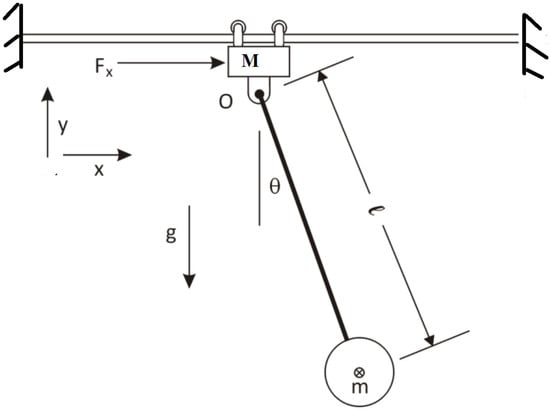
Figure 1.
A diagram of the pendulum–cart system.
Here, , , and for simplicity we use , where m and M denote the cart and pole mass, respectively, while l represents the distance from the center of rod axis rotation to the center of rod mass, g indicates the gravitational acceleration, and F expresses the excitation force. In this system, we assume that the excitation force F is constant. Numerous authors have used several approaches for solving and analyzing different types of equations of motion. For instance, the ansatz method, the Krylov–Bogoliubov–Mitropolsky (KBM) method, and He’s homotopy method were devoted to solving and analyzing the quadratically damped Duffing oscillator [22]. In addition, the nonlinear damped oscillations including the Morse oscillator and a nonlinear harmonic oscillator have been analyzed via the KBM method [23]. Moreover, the generalized KBM method was extended for investigating strong nonlinear oscillators with slowly varying parameters [24]. The (un)forced Duffing–Van der Pol oscillators have been investigated via the KBM method, He’s homotopy method, and He’s frequency–amplitude formulation [25]. The ansatz method is considered one of the most effective methods in finding many approximate analytic solutions to many evolution equations including both ordinary and partial differential equations [26,27,28]. For example, the ansatz method was used to find some approximate solutions to the families of Duffing-type equations, Helmholtz–Duffing-type equations, damped nonplanar Korteweg–de-Vries-type equations, Kawahara-type equations, and Muhammad equations, which have great credit for modeling many nonlinear phenomena that arise in many branches of science in general physics and plasma physics in particular [6,26,27,28,29,30]. Accordingly, the main objective of our investigation is to analyze the PCS (1) in order to find some analytical approximations using both the ansatz and KBM methods. For analyzing the PCS (1) via the ansatz method, we should determine the equilibrium point, while the KBM method does not need to find the equilibrium point.
This investigation is organized in the following fashion: The suggested method for analyzing the pendulum–cart system problem is discussed in detail in Section 1. The obtained approximations are discussed and verified by numerical examples in Section 2. The most important results are summarized in Section 3.
2. Mathematical Approaches for Analyzing System (1)
In this section, we try to find some approximations to system (1) using two different approaches. In the first approach, the ansatz method is employed for analyzing system (1), while in the second approach, the KBM method is applied to find an approximation to system (1).
2.1. First Approach: Ansatz Method
It is clear that system (1) is a coupled system in two independent variables and for solving this system, we first eliminate from system (1), which leads to
Now, it is seen that Equation (3) is an ordinary differential equation (ode) in the variable . Using a Chebyshev approximation, the following approximation to the trigonometric functions is utilized for :
According to the approximate formulas for and given in Equations (4) and (5), the approximate form of Equation (3) reads
Now, for deriving an approximation to Equation (6), the following ansatz is presented:
where and d indicates the equilibrium point. To determine the value of the equilibrium point d, the following MATHEMATICA command is utilized to solve system (1) at :
which leads to
Note that . Now, solving Equation (8) or (9) using the following MATHEMATICA command,
the equilibrium point for is obtained as
which is equivalent to
Note that for , we have .
Note that for vanishing S, we obtain an algebraic equation which can be utilized in determining the value of w as follows:
with
and
On the other side, for , the value of w reads
Furthermore, the period of the oscillator is given by
It remains to find the expression for . To this end, the first equation in system (1) is utilized as
For , solution (20) reduces to
Now, for examining the accuracy of the obtained approximations, the following data in the absence (existence) of the excitation force are considered: kg, kg, m, m/s, , , m, and , while the force is given by
Based on the mentioned data, the i.v.p. for the unforced case to be solved reads
and
Using the same mentioned data for the forced case (), we have
with
The numerical values to the approximate solutions of this problem read
and
The global maximum distance error in the whole domain is calculated for the unforced and forced cases as shown in Table 1.

Table 1.
The global maximum distance error for the ansatz method.
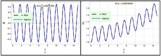
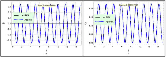
Both solutions (26) and (27) are presented in Figure 2. In Figure 2a, the angle profile according to solution (26) is considered, while the profile of position x is introduced in Figure 2b. Moreover, the forced case is introduced in Figure 3, in which the angle profile according to solution (30) is considered, while the profile of position x given in (31) is displayed. One can see from Figure 2 and Figure 3 as well as the global maximum error given in Table 1 that there is complete congruence between the analytical and numerical approximations, which confirms the high accuracy and effectiveness of the obtained approximations.
2.2. Second Approach: KBM Method
From Equation (3), we obtain
Note here that F can take any value for (in)dependent time, i.e., F may be a constant value or . This property is not fulfilled in the above approach, in which the excitation force must be constant because equilibrium is considered only for autonomous systems.
In order to apply the KBM method, we rewrite problem (34) in the following form of a p-problem (here, ) to enable us to solve this equation:
For applying the KBM method on problem (35), we assume the solution in the following ansatz form:
where each is a periodic function of and both and are defined by
and
where
We define the KBM homotopy as follows:
The approximate analytical solution is obtained at .
Now, to uniquely determine the values of the quantities and , it is required that no contains secularity terms. For sake of simplicity, we assume that , and applying the KBM yields
with
while the values of read
We assume that constant, while the value of reads
Here, the numbers and p are free/optimal parameters which are chosen to obtain the least residual error as possible, and of which the default values read . The value of integration constant B can be obtained from the ICs.
In order to find the value of , we solve the second equation in system (1), i.e., , for
We obtain
Now, applying the Chebyshev approximation on the RHS of Equation (44) yields
By solving the ode (45) using RK4 or MATHEMATICA command “NDSolve” with the help of ICs and , we can obtain the expression for .
For numerical examples, the comparison between the numerical approximation using the RK4 method and the obtained approximations (40) and (45) is presented in Figure 4, Figure 5 and Figure 6 for different values of the excitation force F as follows:
while the other parameters have the same values given in Figure 2 and Figure 3.
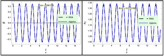
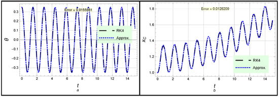
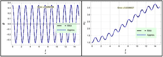
The global maximum error is estimated for the three cases of the excitation force given in Equation (46), as illustrated in Table 2.

Table 2.
The global maximum distance error for the KBM method.
3. Conclusions
The equations of motion for unforced and forced pendulum–cart system oscillators have been solved and analyzed analytically using two accurate and effective approaches. In the beginning, the ansatz method was applied for deriving some effective and accurate approximations in terms of the trigonometric functions. Moreover, the KBM method was carried out to find some approximations to the problem under consideration. In the first approach, it was assumed that the excitation force F must be constant because equilibrium is considered only for autonomous systems. However, in the second approach, the excitation force F could take any value for dependent or independent time, i.e., F could be a constant value or . This feature is not fulfilled in the first approach, in which the excitation force must be constant, because equilibrium is considered only for autonomous systems. Furthermore, the analytical approximations were compared with the numerical approximations using the RK4 numerical approach. In addition, the global maximum distance error with respect to the RK4 numerical approximation was estimated. It was observed that the obtained approximations are characterized by high accuracy and convergence for long periods of time. Moreover, it was found that the accuracy of the obtained approximations using the first approach (ansatz method) is better than that of the second approach (KBM method).
The obtained results can help many authors in studying the mechanism of robotics motion and in investigating many nonlinear oscillations in plasma physics and several fields of science.
Author Contributions
Conceptualization, W.A. and A.H.S.; Data curation, W.A. and S.A.E.-T.; Formal analysis, W.A. and S.A.E.-T.; Investigation, W.A., A.H.S. and S.A.E.-T.; Methodology, A.H.S. and S.A.E.-T.; Project administration, S.A.E.-T.; Resources, S.A.E.-T.; Software, A.H.S. and S.A.E.-T.; Supervision, S.A.E.-T.; Writing – original draft, W.A. and A.H.S.; Writing – review & editing, S.A.E.-T. All authors contributed equally and approved the final manuscript.
Funding
This research received no external funding.
Institutional Review Board Statement
Not Applicable.
Informed Consent Statement
Not Applicable.
Data Availability Statement
All data generated or analyzed during this study are included in this published article (more details can be requested from El-Tantawy).
Acknowledgments
The authors express their gratitude to Princess Nourah bint Abdulrahman University Researchers Supporting Project number (PNURSP2022R229), Princess Nourah bint Abdulrahman University, Riyadh, Saudi Arabia.
Conflicts of Interest
The authors declare that they have no conflicts of interest.
References
- Albalawi, W.; Salas, A.H.; El-Tantawy, S.A.; Youssef, A.A.A. Approximate analytical and numerical solutions to the damped pendulum oscillator: Newton–Raphson and moving boundary methods. J. Taibah Univ. Sci. 2021, 15, 479–485. [Google Scholar] [CrossRef]
- Salas, A.H.; El-Tantawy, S.A. On the approximate solutions to a damped harmonic oscillator with higher-order nonlinearities and its application to plasma physics: Semi-analytical solution and moving boundary method. Eur. Phys. J. Plus 2020, 135, 833. [Google Scholar] [CrossRef]
- He, J.; El-dib, Y.; Mady, A.A. Homotopy Perturbation Method for the Fractal Toda Oscillator. Fractal Fract. 2021, 5, 93. [Google Scholar] [CrossRef]
- Aljahdaly, N.H.; El-Tantawy, S.A. On the multistage differential transformation method for analyzing damping Duffing oscillator and its applications to plasma physics. Mathematics 2021, 9, 432. [Google Scholar] [CrossRef]
- El-Tantawy, S.A.; Salas, A.H.; Alharthi, M.R. A new approach for modelling the damped Helmholtz oscillator: Applications to plasma physics and electronic circuits. Commun. Theor. Phys. 2021, 73, 035501. [Google Scholar] [CrossRef]
- Salas, A.H.; El-Tantawy, S.A.; Alharthi, M.R. Novel solutions to the (un)damped Helmholtz-Duffing oscillator and its application to plasma physics: Moving boundary method. Phys. Scr. 2021, 96, 104003. [Google Scholar] [CrossRef]
- Pedersen, H.B.; Madsen, M.L.; Andersen, J.E.V.; Nielsen, T.G. Investigation of argumental oscillations of a physical pendulum. Eur. J. Phys. 2021, 42, 025012. [Google Scholar] [CrossRef]
- Korytov, M.S.; Shcherbakov, V.S.; Titenko, V.V.; Belyakov, V.E. Spherical pendulum model with a moving suspension point in the problem of spatial load movement by a hoisting crane with oscillation limiting. J. Phys. Conf. Ser. 2020, 1441, 012102. [Google Scholar] [CrossRef]
- Johannessen, K. An approximate solution to the equation of motion for large-angle oscillations of the simple pendulum with initial velocity. Eur. J. Phys. 2010, 31, 511. [Google Scholar] [CrossRef]
- Butikov, E.I. Oscillations of a simple pendulum with extremely large amplitudes. Eur. J. Phys. 2012, 33, 1555. [Google Scholar] [CrossRef]
- Uy, R.F.; Yuan, C.; Chai, Z.; Khor, J. Wilberforce pendulum: Modelling linearly damped coupled oscillations of a spring-mass system. Eur. J. Phys. 2022, 43, 015011. [Google Scholar] [CrossRef]
- Owen, F. Pendulum on a Cart via Lagrangian Mechanics; Alpha Omega Engineering, Inc.: Sutton, MA, USA, 2014; Available online: http://www.aoengr.com/Dynamics/PendulumOnCart.pdf (accessed on 23 May 2014).
- Singla, A.; Singh, G. Real-Time Swing-up and Stabilization Control of a Cart-Pendulum System with Constrained Cart Movement. Int. J. Nonlinear Sci. Numer. Simul. 2017, 18, 525–539. [Google Scholar] [CrossRef]
- Neria, M.R.; Ramirez, S.H.; Moctezuma, R.G.; Juarez, A.L. Linear active disturbance rejection control of underactuatedsystems: The case of the Furuta pendulum. ISA Trans. 2014, 53, 920–928. [Google Scholar] [CrossRef] [PubMed]
- Kumar, V.; Jerome, J. Robust LQR controller design for sta-bilizing and trajectory tracking of inverted pendulum. Procedia Eng. 2013, 64, 169–178. [Google Scholar] [CrossRef]
- Ogata, K. Modern Control Engineering; Prentice-Hall: New York, NY, USA, 2000. [Google Scholar]
- Mori, S.; Nishihara, H.; Furuta, K. Control of unstablemechanical system- control of pendulum. Int. J. Control 1976, 23, 673–692. [Google Scholar] [CrossRef]
- Anderson, C.W. Learning to control an inverted pendulum usingneural network. IEEE Control Syst. Mag. 1989, 9, 31–37. [Google Scholar] [CrossRef]
- Boubaker, O. The inverted pendulum benchmark in nonlinearcontrol theory. Int. J. Adv. Rob. Syst. 2013, 10, 1–9. [Google Scholar]
- Song, Z.; Song, X.; Liu, C.; Zhao, Y. Research on real-timesimulation and control of linear 1-stage inverted pendulum. J. Comput. 2013, 8, 896. [Google Scholar] [CrossRef][Green Version]
- Eide, R.; Egelid, M.; Stamso, A.; Karimi, H.R. LQG controldesign for balancing an inverted pendulum mobile robot. Intell. Control Autom. 2011, 2, 160–166. [Google Scholar] [CrossRef]
- Salas S, A.H. Analytical Approximant to a Quadratically Damped Duffing Oscillator. Sci. World J. 2022, 2022, 3131253. [Google Scholar] [CrossRef] [PubMed]
- Yamgoué, S.B.; Kofané, T.C. Application of the Krylov–Bogoliubov–Mitropolsky method to weakly damped strongly non-linear planar Hamiltonian systems. Int. J. Non-Linear Mech. 2007, 42, 1240–1247. [Google Scholar] [CrossRef]
- Cai, J. A Generalized KBM Method for Strongly Nonlinear Oscillators with Slowly Varying Parameters. Math. Comput. Appl. 2007, 12, 21–30. [Google Scholar] [CrossRef]
- Salas, A.H.; Albalawi, W.; El-Tantawy, S.A.; El-Sherif, L.S. Some Novel Approaches for Analyzing the Unforced and Forced Duffing–Van der Pol Oscillators. J. Math. 2022, 2022, 2174192. [Google Scholar] [CrossRef]
- Alyousef1, H.A.; Alharthi, M.R.; Salas, A.H.; El-Tantawy, S.A. Optimal analytical and numerical approximations to the (un)forced (un)damped parametric pendulum oscillator. Commun. Theor. Phys. 2022. Available online: https://iopscience.iop.org/article/10.1088/1572-9494/ac7bdc/pdf (accessed on 24 June 2022).
- Salas, A.H.; Albalawi, W.; Alharthi, M.R.; El-Tantawy, S.A. Some Novel Solutions to a Quadratically Damped Pendulum Oscillator: Analytical and Numerical Approximations. Complexity 2022, 2022, 7803798. [Google Scholar] [CrossRef]
- Alyousef, H.A.; Salas, A.H.; Alkhateeb, S.A.; El-Tantawy, S.A. Some Novel Analytical Approximations to the (Un)damped Duffing–Mathieu Oscillators. J. Math. 2022, 2022, 2715767. [Google Scholar] [CrossRef]
- El-Tantawy, S.A.; Salas, A.H.; Alharthi, M.R. On the analytical and numerical solutions of the damped nonplanar Shamel Korteweg–de Vries Burgers equation for modeling nonlinear structures in strongly coupled dusty plasmas: Multistage homotopy perturbation method. Phys. Fluids 2021, 33, 043106. [Google Scholar] [CrossRef]
- El-Tantawy, S.A.; Salas, A.H.; Alharthi, M.R. On the Analytical and Numerical Solutions of the Linear Damped NLSE for Modeling Dissipative Freak Waves and Breathers in Nonlinear and Dispersive Mediums: An Application to a Pair-Ion Plasma. Front. Phys. 2021, 9, 580224. [Google Scholar] [CrossRef]
Publisher’s Note: MDPI stays neutral with regard to jurisdictional claims in published maps and institutional affiliations. |
© 2022 by the authors. Licensee MDPI, Basel, Switzerland. This article is an open access article distributed under the terms and conditions of the Creative Commons Attribution (CC BY) license (https://creativecommons.org/licenses/by/4.0/).
