1. Introduction
Origami is the basis for many deployable mechanisms, including self-scaling, modular robots [
1], satellite reflectarray antennas that pack efficiently [
2], and multimodal biomedical devices that actuate electromagnetically [
3]. Zipper-coupled tubes are multistable origami structures that fold up compactly and unfold bidirectionally to fill space and resist compression [
4]. An asymmetric generalization of zipper-coupled tubes with smooth sheet attachments was introduced previously [
5]. Together, these origami-based mechanisms form a deployable device with a smooth surface that is advantageous in applications, such as prefab architecture, when drivability and walkability are important, and in smooth medical devices, when sharp edges could harm the body. The smooth sheet attachment we presented previously, however, does not fully cover the surface of zipper-coupled tubes without additional flaps that actuate separately [
5]. We rectify this problem by offering an alternative, Miura-ori inspired [
6,
7,
8], construction of a smooth sheet attachment that fully covers the surface of, and deploys simultaneously with, asymmetric zipper-coupled tubes.
In this paper we briefly review the design of asymmetric zipper-coupled tubes and then demonstrate how to (1) construct a Miura-ori inspired smooth sheet attachment without gaps that attaches to the mountain folds of asymmetric zipper-coupled tubes and (2) handle design variations in the symmetric case. We present a mathematically robust design method, decomposing the attachment into pairs of compatible, tessellating cells inspired by the Miura-ori pattern and then defining the cells’ vertices throughout the folding motion, thereby confirming rigid-foldability of the smooth sheet attachment and highlighting the mathematical processes involved in mechanism design. Our Miura-ori-based smooth sheet attachment expands the utility of asymmetric zipper-coupled tubes; combined, these origami-inspired mechanisms are ideal for applications requiring a rigidly deployable structure with a smooth surface.
2. Zipper-Coupled Tubes Review
Zipper-coupled tubes are an origami pattern consisting of two or more deployable tubes coupled together in a zipper fashion that makes their motion compatible. Designed by Filipov et al., this structure is remarkable for its ability to deploy from a flat, stowable form into a stable, space-filling structure with only one degree of freedom [
4]. In this section we review briefly the construction of asymmetric zipper-coupled tubes from two tube segments that are each, in turn, composed of two degree-four vertex cells; the interested reader may refer to our previous work for a thorough treatment of the construction [
5].
Throughout this paper we use the notational convention that an arbitrary vector
has unit length direction vector
with length
x, and hence
Thus, the notation
always represents a unit length vector associated with a vector denoted
, where
.
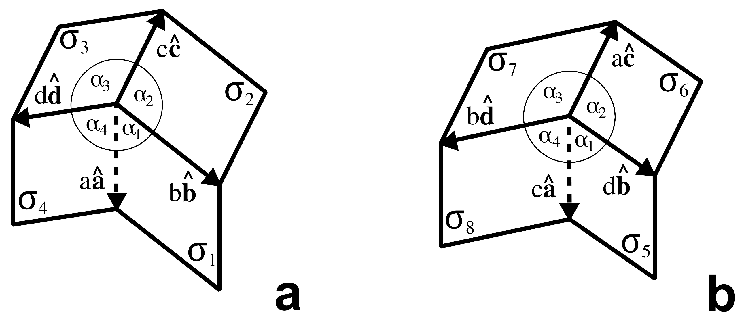
The building blocks for zipper-coupled tubes are the compatible degree-four vertex cells
and
illustrated in
Figure 1 and
Figure 2. When combined, they form a single tube segment [
5]. To couple correctly and satisfy rigid and flat-foldability [
9], the design constraints of these degree-four vertex cells include:
If
, the zipper-coupled tubes are called
asymmetric, having a characteristic tilt and a customizable unfolding motion. In the special case that
and
, the two cells in
Figure 1 are congruent, symmetric Miura-ori cells and the resulting zipper-coupled tubes are those constructed by Filipov et al. [
4].
Like a Miura-ori cell, the basic degree-four vertex cell has one degree of freedom in its motion. Let the basic and complementary cells lie flat in the
-plane when unfolded, as depicted in
Figure 1 and
Figure 2, and let the angles between the
-plane and panels
and
, respectively, be equal as
and
fold toward each other (see
Figure 1a). Call this motion parameter
. Then, placing
at the origin and fixing
on the negative
z-axis in
(see
Figure 2a), the motion of the basic cell is determined by the following vector paths:
where
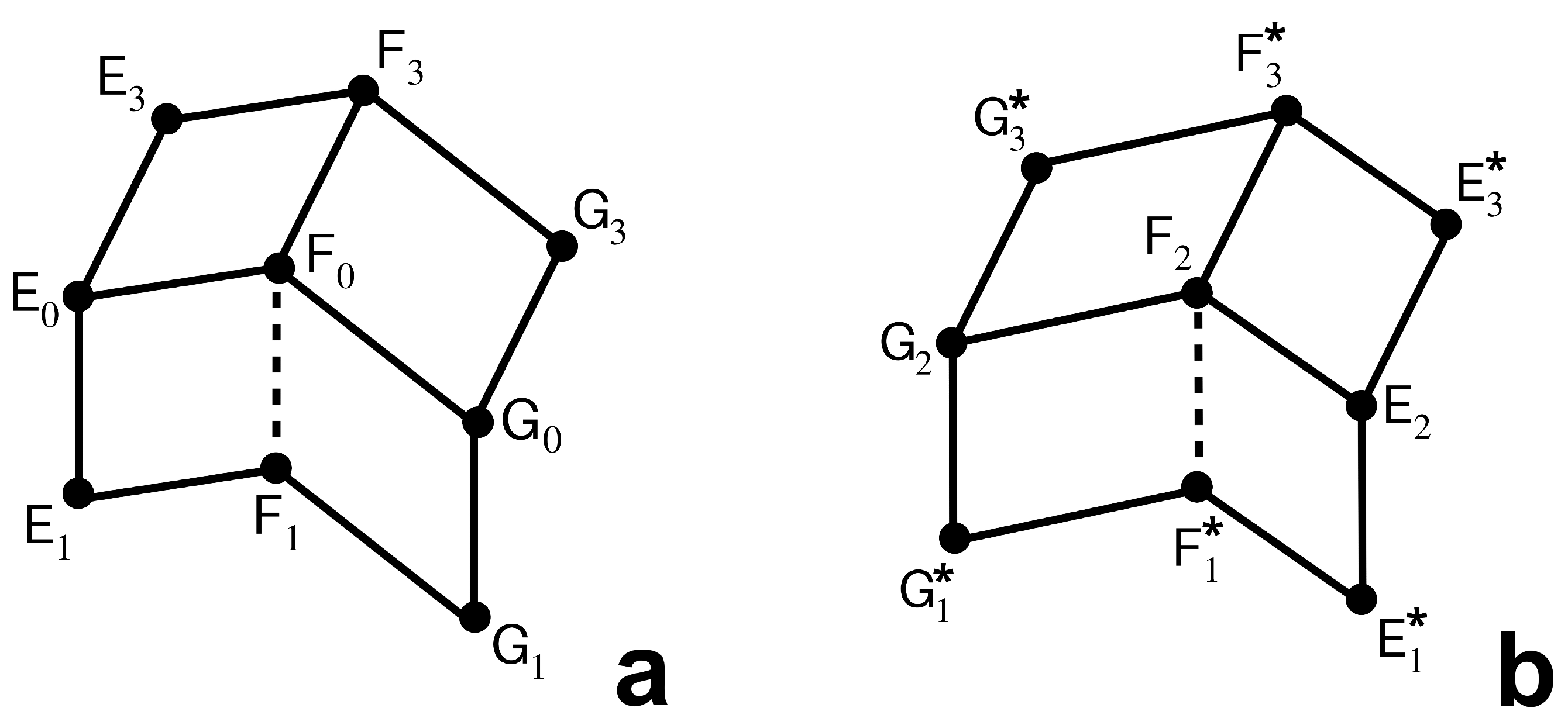
The same vectors define the motion of both basic and complementary cells. By combining one basic cell (
) and one complementary cell (
), we obtain the first tube segment in a zipper-coupled pair, illustrated in
Figure 3a. Its vertices, identified with their corresponding position vectors, are given by:
The second tube segment is a copy of the first, but rotated
about the
y-axis and then shifted by an offset vector so that it attaches to the first tube segment along the vertical creases (illustrated in
Figure 3b). Let
and
denote the copies of
and
, respectively, comprising the second tube segment. To define the motion of the second tube segment, let
denote the
rotation of a vector
about the
y-axis and define the offset vector:
Then the vertices of the second tube segment are defined by:
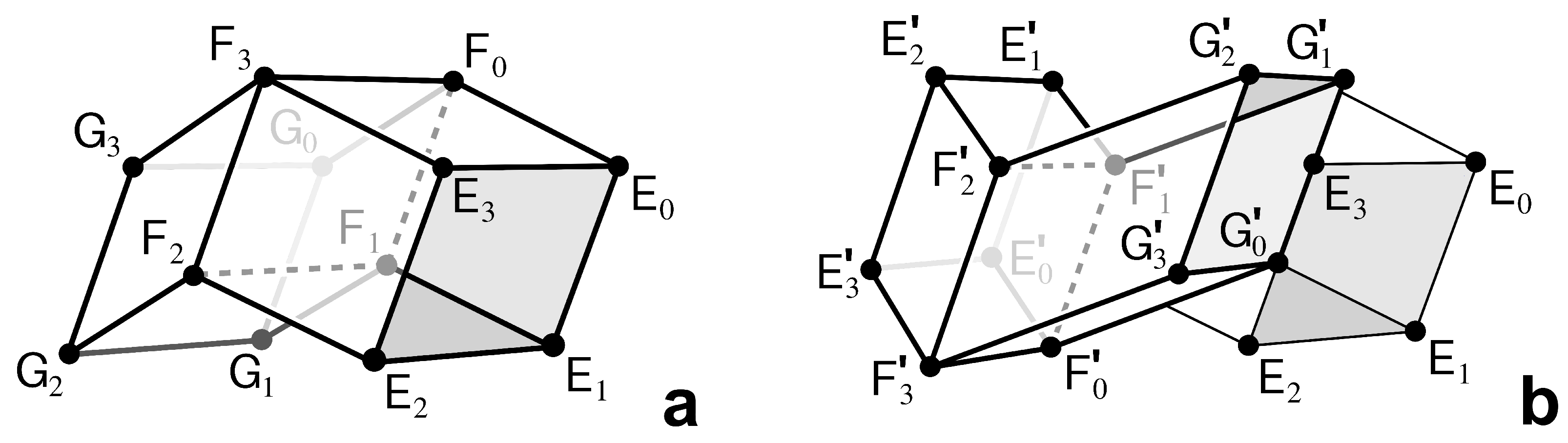
The pair of tube segments, with vertices positioned as indicated above, form a single component in a pair of zipper-coupled tubes (
Figure 3b), which will be denoted as
. The zipper-coupled tubes can be extended by taking multiple copies of
and attaching them end-to-end. In particular, for
, let
Then
denotes zipper-coupled tubes with
components.
Of critical importance, at a certain point in the motion of
, the upper (or lower) creases simultaneously become coplanar, as bolded in
Figure 4b. This state is the
ideal state, and it occurs at a parameter value:
The value will be the terminal value for the deployment of with a smooth sheet attachment. Thus, by construction, the smooth sheet attachment lies flat on the surface of the zipper-coupled tubes when and folds up with the zipper-coupled tubes until , at which point the entire structure lies in a plane and has no volume.
3. Asymmetric Smooth Sheet Attachment
In this section we design a Miura-ori inspired smooth sheet attachment that actuates simultaneously with the asymmetric zipper-coupled tubes pattern, folding up flat and unfolding into a rigid sheet without gaps in the ideal state. This additional pattern broadens the potential applications of the zipper-coupled tubes structure and expands on the design of the attachment described previously [
5]. As with the zipper-coupled tubes, we decomposed the overall structure into its basic units: four distinct smooth sheet cells that tesselate. We define the vectors used to construct each cell to describe the motion of the cell’s vertices and confirm its compatibility with the zipper-coupled tubes structure.
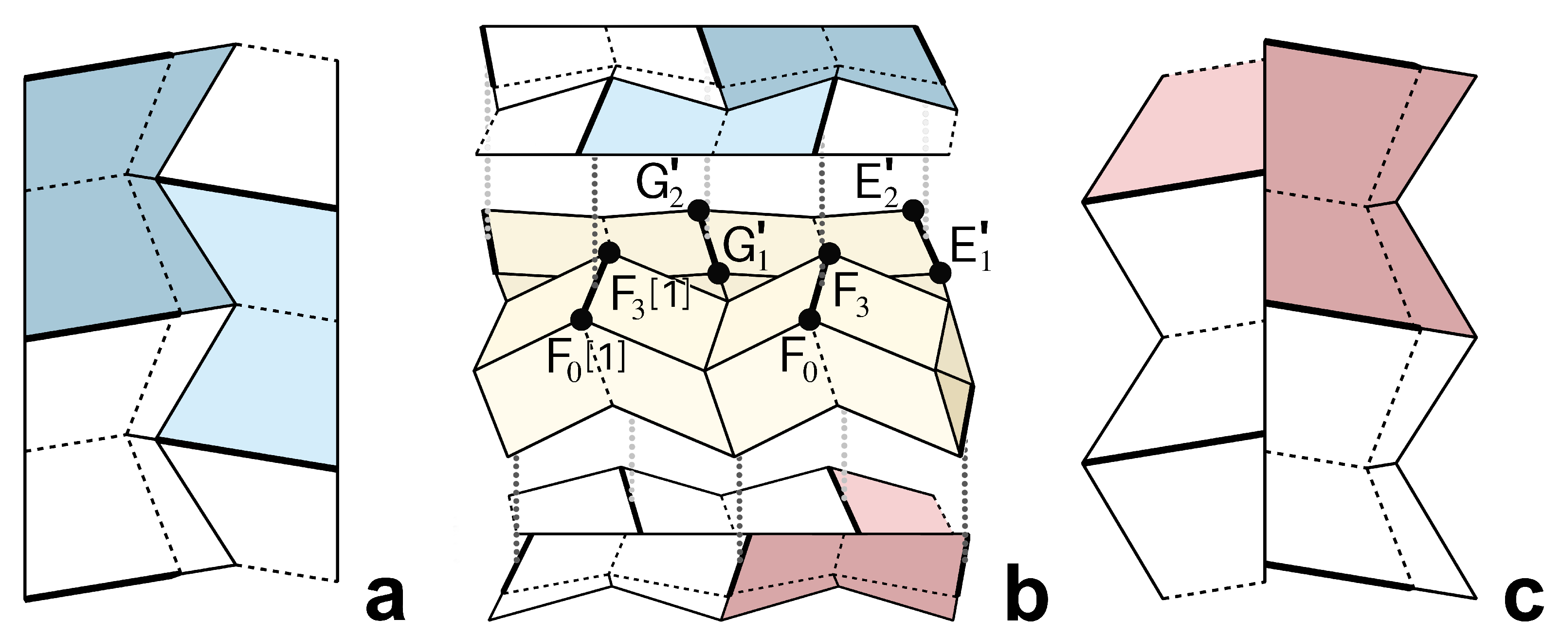
The seamless smooth sheet attachment consists of four distinct cells denoted
, for
. In
Figure 4a, the lightly shaded cell is
and the darkly shaded cell is
, while in
Figure 4c, the lightly shaded cell is half of
and the darkly shaded cell is
. Cells
and
share the same configuration, but like the zipper-coupled tube segments, one is rotated
about the
y-axis; the same is true of
and
. The manner in which the smooth sheet cells attach to
in the ideal state (
) is highlighted in
Figure 4b. When the mechanism is fully deployed, cells on the top sheet meet along their jagged edges, as seen in
Figure 4a. The cells on the bottom sheet, however, meet along their straight edges, as seen in
Figure 4c—this is a key feature in defining a design that will cover zipper-coupled tubes without gaps and deploy without restricting the tubes’ motion up to the ideal state.
Regarding the single component
, the cell
attaches to
. However, whereas the cells
and
form a bridge between a pair of creases in
, the cells
and
form a bridge between a crease of
and a crease of
(bolded in
Figure 4b). Upon careful examination of the zipper-coupled tubes, we observed that
can be designed as though it bridged two creases of
and then moved to bridge creases of the copies of
in
and
; this strategy eliminates some complexity in defining
. In contrast,
is designed directly, transversing the two creases of
where it attaches. Designing both cells atop
allows us to re-use the same vectors and enables the interested reader to easily compare the Miura-ori inspired cells and the original smooth sheet cells with gaps [
5].
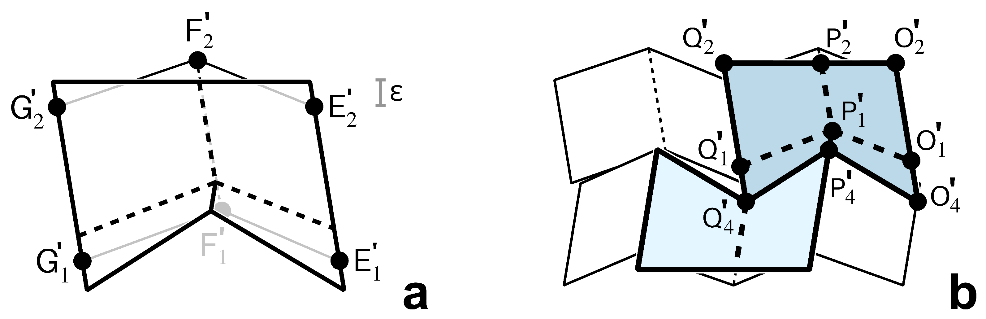
3.1. Design of
The first smooth sheet cell,
, has two panels that fold toward each other as the zipper-coupled tubes fold up. We first discuss the design of
when built atop
—the desired relation between
and
is shown in
Figure 5a. The vectors that define
in this temporary configuration will be re-used to define
, allowing the edges of these two cells to mesh when placed opposite each other. After construction, the smooth sheet cell
will be moved to attach to
, as seen in
Figure 5b.
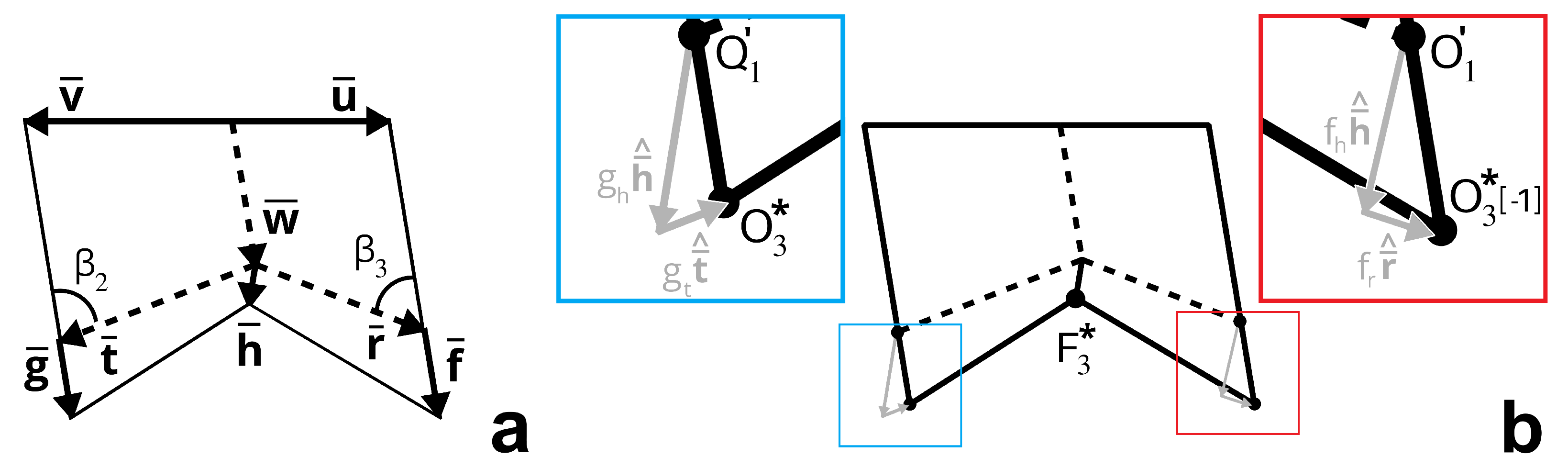
In preparation of the design of
, let the displacement between
and
be described by
and
As depicted in
Figure 6a,b,
is the component vector of
orthogonal to
, the displacement between
and
(or equivalently, the displacement between
and
). In the ideal state of the zipper-coupled tubes, the distance between the ridges of
on which the smooth sheet will be attached is
Note that, of necessity and by design, the top edges of both
and
are parallel with
. To remove gaps between zipper-coupled tubes stacked laterally to
and in anticipation of the behavior depicted in
Figure 4c, we extended the side edges of
in the direction of
by the length
, as shown in
Figure 5a and
Figure 6a, where
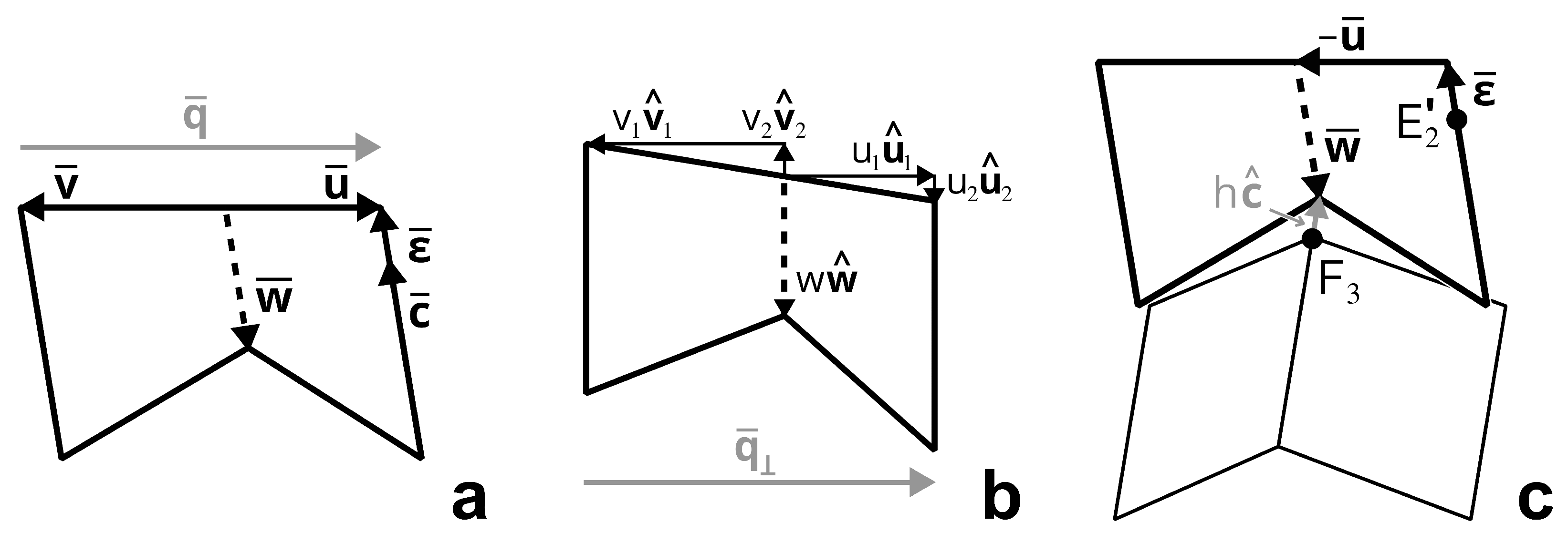
The smooth sheet cell is determined by the vectors
,
, and
illustrated in
Figure 6a. As highlighted in
Figure 6b, let
Note that
. Examining the components of
and
in the ideal state, as shown in
Figure 6a,b, we see that
. Since
it follows that
Rodrigues’ rotation formula [
10] rotates a vector
by angle
in a counter-clockwise direction about a unit vector
, and is given by:
Then we define
and
as
In order to satisfy flat-foldability, the direction of the vector
must be the same as the direction of
. Thus, for some positive constant
w:
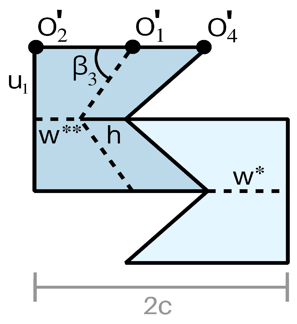
The primary concern in choosing the length
w was to avoid intersections with the zipper-coupled tubes during deployment. So that the smooth sheet cells
and
lined up correctly, we defined
w and
h to be the lengths necessary so that in the ideal state, the tips of the vectors
(
) and
meet, as shown in
Figure 6c. In particular, we set
Then,
w (and
h) can be obtained as follows:
where the function
is defined such that
Remark 1. Note that the matrix that is inverted in Equation (5) will be singular only in the symmetric case when has the same direction as . We have now stipulated all three vectors—
,
, and
—which define
when it is attached to
. What remains is to move
so that it attaches to
. The desired placement is depicted in
Figure 5b, where
is positioned on top of
and bridges
and
; note that the zipper-coupled tubes have been rotated about the
y-axis in this figure so that
lies parallel with the
-plane (see [
5] for further details). Let
denote the point in
that is a copy of
X in
, for
. Then, the vertex
in
attaches to
in
and the vertex
in
attaches to
in
. More particularly, the edge
attaches to
and
attaches to
.
Recall that the
rotation of a vector
about the
y-axis is denoted
. Thus, the vertices in
when attached to
as desired are:
3.2. Design of
The cell
is a rotated copy of
attached to
, so the vectors that define
are rotated copies of the vectors that define
, shifted by
. Let the vertices on smooth sheet cells attached to the rotated tube segment in
—i.e., the vertices in
and
—be denoted with primes. Note that the smooth sheet cell
bridges
and
, so the smooth sheet cell contains the vertices
and
. Thus, the vertices of
when attached to
are:
3.3. Design of
The smooth sheet cell
attaches on top of
and fits together with
in the ideal state, as illustrated in
Figure 7. We make the edge of
opposite of
straight in the ideal state so that zipper-coupled tubes with smooth sheet attachments can be stacked laterally without gaps. From another point of view, the edge is made straight in preparation of the design of
, a copy of
attached to the bottom of
—the straight edges of
and
meet in the ideal state, as illustrated in
Figure 4c.
The smooth sheet cell
has a degree-four vertex folding pattern inspired by the Miura-ori cell, as shown in
Figure 8a. This allows the cell to close the gap on the top of
in the ideal state and fold up without intersecting the adjacent tube segment. For flat-foldability of the cell, we require the sum of opposite angles at the interior vertex to be
(see Kawasaki-Justin theorem [
11,
12]). The pattern in
Figure 8a is described by the previously defined vectors
,
, and
and the yet-to-be-defined vectors
,
,
,
, and
.
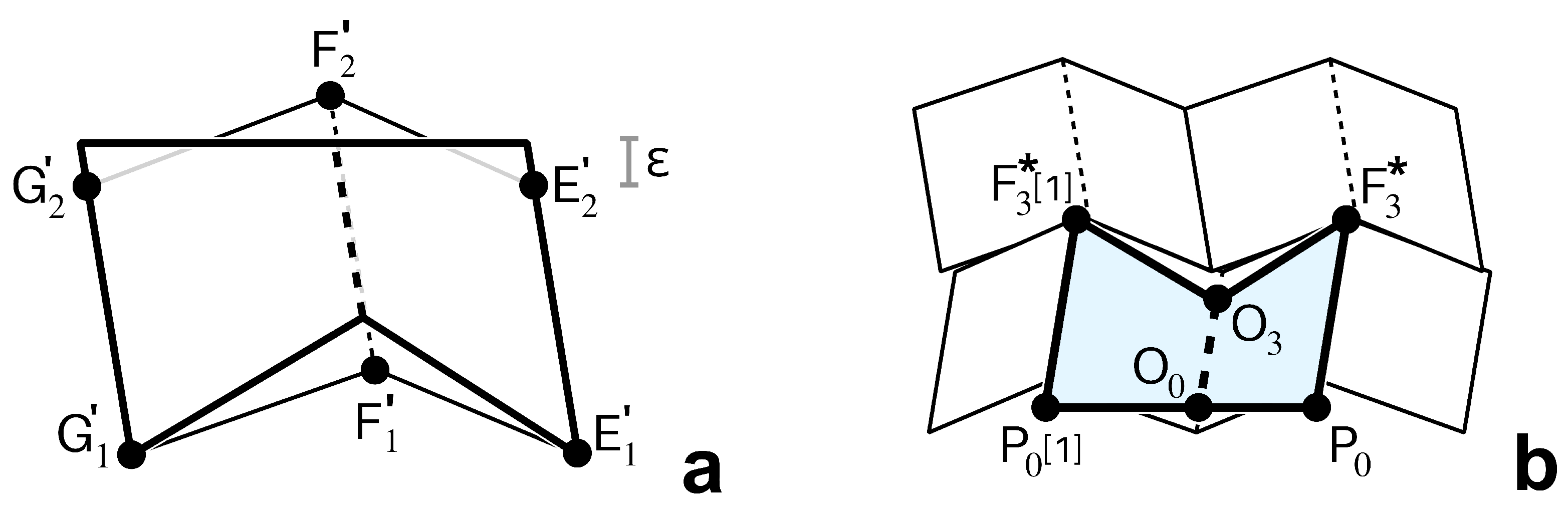
In the ideal state,
and
are the projections of
and
, respectively, into the xy-plane; this is necessary to ensure flat foldability. Thus (see
Figure 3 and
Figure 8a),
Having derived these angles, we are now ready to define
and
as follows (see Equations (
1)–(4)):
Observing
Figure 8a, note that
r and
t can be expressed simply as:
In the ideal state, the crease defined by
must have the same direction as
to satisfy flat-foldability. Moreover, so that there are no gaps when
and
come together in the ideal state, the length of
should be the value
h given by Equation (
5), according to the premise upon which Equation (
5) was derived (see also
Figure 6c). Thus,
For an arbitrary parameter value
, the unit vectors adjacent to
that emanate from the degree-four vertex in the interior of
are
and
. Because opposite angles in a degree-four vertex sum to
[
11,
12] and we require a rigid folding,
is determined by the following system of equations:
The first two equations are linear and the third is quadratic. Hence, there are precisely two solutions: one corresponding to a valley fold assignment and one corresponding to a mountain fold assignment. The solution corresponding to a mountain fold is the correct solution.
Because
corresponds to an edge of the panel defined by
and
, we can define it in terms of these vectors. We want the position of vertex
in
to equal that of
in
when in the ideal state. This is equivalent to saying that
and
define the same point when the former is extended from
and the latter is extended from
in the ideal state, as shown in
Figure 8b. The reader will recognize that this problem is formulated similarly to that in the end of
Section 3.1, where the lengths
h and
w were computed using a system of equations based on two intersecting vectors. We employ the same technique, with the following system of equations:
giving us
We solve for
and
and use these components of projection to define
, using
and
as a basis:
We define
similarly, solving for
and
via the same method and another system of equations:
Now that we have defined all the essential vectors in
, we are ready to attach the degree-four vertex to
in the zipper-coupled tubes structure. In the ideal state, this smooth sheet cell matches exactly with the edges of
, providing a smooth surface devoid of gaps on the top of asymmetric zipper-coupled tubes (
Figure 4a). In particular, the edge
attaches to
and
attaches to
. Likewise, the edges
and
align perfectly with adjacent cells in the ideal state and fold up at different rates to avoid intersections. The vertices in
identified with their corresponding position vectors are:
3.4. Design of
The smooth sheet cell
is a rotated copy of
that attaches to
. The vertices in this smooth sheet cell are
We have now completed the details for the smooth sheet attachment in the asymmetric case; a summary of the edges and vertices in the attachment is given in
Table A1 and
Table A2, suppressing
for concision. This attachment folds up flat and actuates with the zipper-coupled tubes structure to form a smooth surface, leaving no gaps between the various asymmetric cells we have described. The symmetric case merits more discussion, however, because there are fewer constraints on the vectors in the
, allowing for multiple rigidly foldable patterns given specific design parameters.
4. Symmetric Smooth Sheet Attachment
Unlike their asymmetric counterparts, symmetric zipper-coupled tubes have no tilt and fold parallel with the
x-axis [
5]. Furthermore, the center creases in
and
lie parallel with the
y-axis in the ideal state, as illustrated in
Figure 9. There are multiple valid lengths for these creases, therefore, in a design that covers all the gaps in the surface while maintaining rigid foldability without prohibitive intersections. In this section we comment on the diversity in symmetric, Miura-ori inspired smooth sheet cell construction and recommend values for certain lengths.
The design parameters for the smooth sheet cells
are uniquely determined for all cases where
. When
, however, there is no longer a unique solution to Equation (
5). In particular,
has the same direction as
in the symmetric case, so the matrix inverted in Equation (
5) is singular and the values
h and
w are not uniquely defined. Similarly,
and
are no longer constrained, and we may define these features of the design problem advantageously by choosing a solution that minimizes the amount by which the smooth sheet attachment protrudes from the structure when folded.
In the design of
and
, let
replace the value of
w. Likewise, in the design of
and
, let
replace the value of
w. As highlighted in
Figure 9, for the symmetric case we no longer require that
. In selecting a value for
, we set it as large as possible to maximize the surface area of
, thus minimizing the amount by which the edges of
can protrude from the zipper-coupled tubes structure. Applying the analysis given in [
5] (see Section 7.1.3), the largest value for
can be shown to be
The only requirements for
h,
,
, and
in the symmetric case are
Adjustments to the values h, , , and can also assist in minimizing the protrusion of from the zipper-coupled tubes. Optimal values can be determined by numerical methods according to the specific design application. However, care should be taken in making these adjustments to avoid intersections with the structure underneath.
On a final note, although
and
are determined after defining the previous quantities, a convenient simplification in their definition: because
is symmetric, the vectors
and
are parallel to
and have equal lengths. Moreover, in the ideal state,
5. Conclusions
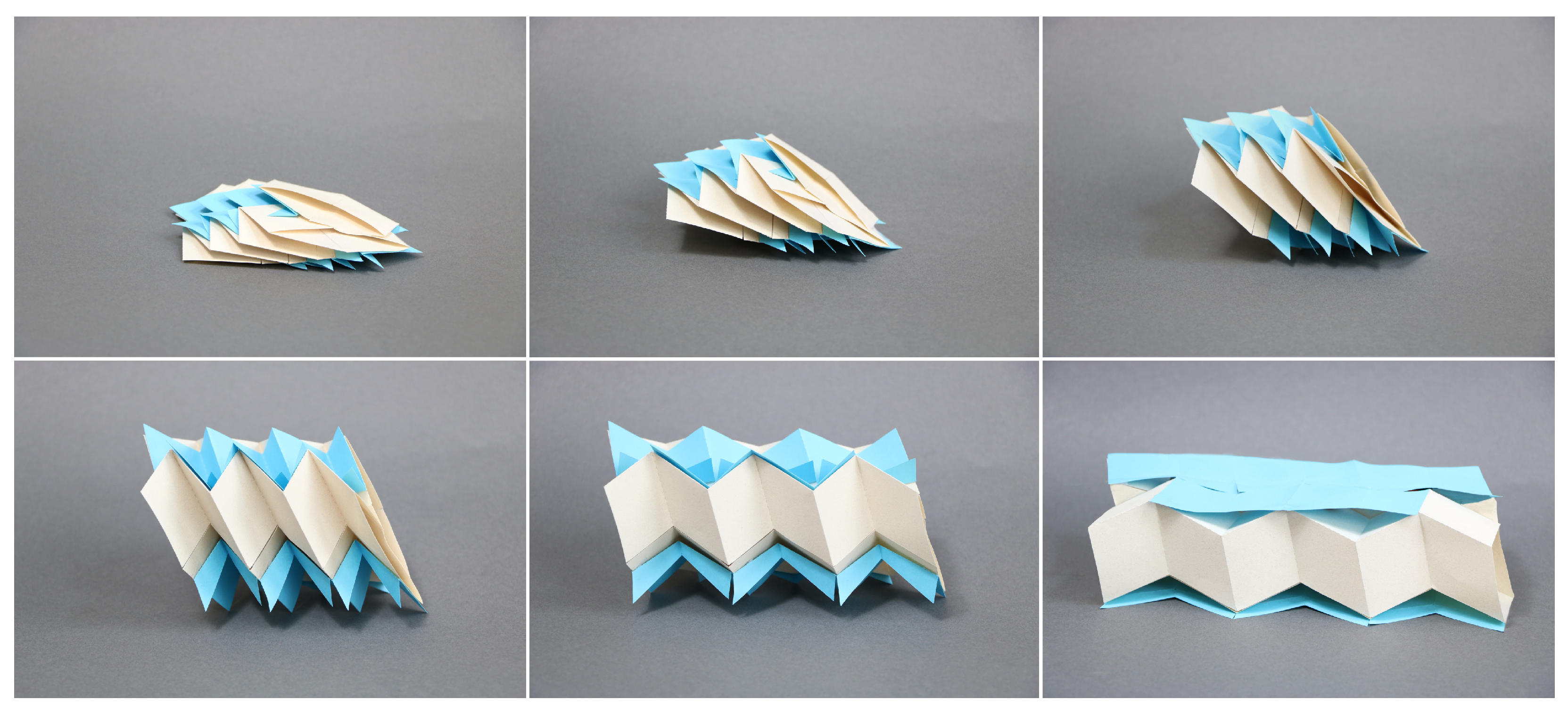
We have successfully defined a smooth sheet attachment that folds up with the zipper-coupled tubes and unfolds to the ideal state without inhibiting their motion to form a flat surface without any gaps (
Figure 10). This pattern is defined for both the asymmetric and symmetric cases, and we provide access to code which the reader may use to visualize the origami structures described and print out the corresponding fold patterns:
https://github.com/dylanwebbc/azct (accessed on 23 July 2022).
Note that the smooth sheet cells protrude from the zipper-coupled tubes structure when folded. When gaps are tolerable and the folded state must be minimized for transportation, constraining the cells to fold up within the zipper-coupled tubes while maximizing surface area in the ideal state results in the smooth sheet attachment described previously [
5]. Thus, the smooth sheet design can be tailored to the situation, much like zipper-coupled tubes themselves. To inform future applications of these structures, we suggest dynamic and quasi-static analyses. Constructing a device for architectural applications will likely require the use of thick origami and compliant hinges, and remote self-actuation via magnetism or heat could be useful in space or medical applications [
13,
14,
15].
Miura-ori-inspired smooth sheet attachments enhance the utility of zipper-coupled tubes in various situations. The tubes are useful in architecture because they pack tight and deploy to a rigid state [
4]; our gapless smooth sheet attachments improve existing designs by increasing drivability and walkability. If a local bridge collapses, for example, a prefabricated bridge based on zipper-coupled tubes with smooth sheet attachments can easily be transported on a single vehicle and swiftly deployed on-site to provide smooth, emergency transit. Space structures are another popular application of origami-inspired mechanisms—the Miura-ori pattern that the smooth sheet is based on is common in deployable space array design. Accommodating for material thickness, however, makes Miura-ori sheets challenging to deploy [
16]. In contrast, a thin solar array constructed from Miura-ori inspired smooth sheet cells can deploy rigidly because it is supported by zipper-coupled tubes.
The design of smooth sheet attachments without gaps is key to the development of more versatile zipper-coupled tubes. We have communicated a clear design method for the origami-based structure, examining the mathematics of its motion in detail. By elucidating the possibility for further enhancements on the zipper-coupled tubes structure, we hope to spur many novel and exciting applications beyond those mentioned.


