Article

3-D Flow of Magnetic Rotating Hybridizing Nanoliquid in Parabolic Trough Solar Collector: Implementing Cattaneo-Christov Heat Flux Theory and Centripetal and Coriolis Forces

1
Department of Mathematics, Faculty of Science, New Valley University, Al-Kharga 72511, Al-Wadi Al-Gadid, Egypt
2
Department of Mathematics, Faculty of Science, Northern Border University, Arar 1321, Saudi Arabia
Mathematics 2022, 10(15), 2605; https://doi.org/10.3390/math10152605
Submission received: 22 June 2022 / Revised: 21 July 2022 / Accepted: 23 July 2022 / Published: 26 July 2022

Abstract

:
Current research proposes a model for assessing the flow properties and heat transmission from hybridized nanofluids to solar collectors (SCs). A theoretical investigation that was based on the application of alumina-water (Al2O3-H2O) conventional nanofluid and copper/alumina-water (Cu-Al2O3/H2O) hybrid nanofluid has been considered between two rotating plates in parabolic trough solar collector (PTSC). The Cattaneo–Christov model (CCM) for heat fluxing is used for the thermal boundary layer analysis. The impact of centripetal and Coriolis forces on the swirling flow has been considered. Adequate transformations are utilised for the conversion of the regulating partial differential equations (PDEs) into a group of dimensionless ordinary differential equations (ODEs). Dimensionless ODEs are then tackled by the Keller box method (KBM) in the MATLAB program. The basic concept of this study is to inspect the influences of change in substantial factors on velocities, temperature, and heat transmission rate for both Al2O3-H2O mono nanofluid (MNF) and Cu-Al2O3/H2O hybridized nanofluid (HBNF). The striking feature of the investigation is that the hybrid nanofluid Cu-Al2O3/H2O has a less frictional force and an elevated heat transmission rate (RHT) as assessed with the traditional nanoliquid Al2O3-H2O. Consequently, the rotating factor slows RHT on the surface. In this case study, HBNF is better than the mono NF as a thermal and electrical conductor.

1. Introduction

As the world opts for using more green energy, solar energy is one of the forerunners as clean energy to replace fossil fuel and conventional energy sources. A solar collector is the main tool that is used to harness the sun’s energy and increasing its efficiency is a main concern and a focus of researchers in the discipline of energy development. Back in 1995, a new group of fluids emerged named nanofluids [1], displaying interesting thermophysical properties; using them in a solar collector as working fluids contributed to increasing the its efficient. Thus, a considerable number of studies were done on exergy efficiency and entropy generation of solar collectors that were employing nanofluids. Alklaibi et al. [2], Joseph et al. [3], and Eltaweel et al. [4] analyzed these parameters experimentally inside a flat plate solar collector employing diamond/H2O nanofluid, PTSC applying SiO2/Ag-CuO NF, and an abandoned tube solar collector manipulating MWCNT/H2O NF. For further reading see Singh et al. [5], Kaya et al. [6], and Olfian et al. [6]. A wide range of fluids hold important positions in manufacturing procedures. Nonetheless, these liquids have slight small thermal conductivity. As a result, they do not use large thermal exchange rates in thermal management devices. Using extremely small-sized solid molecules that are dispersed in broad liquids to improve heat conductivity is one technique to overcome this barrier. NF is the presence of nano-sized molecules (1–100 nm) in a traditional base fluid. NFs have improved stability, rheological properties, and much greater thermal conductivity [7]. The use of NFs in collectors and water heaters is being studied from the standpoints of effects, economics, and the environment; some studies on the thermal conductivity and optical properties of NFs have been published [8]. SCs are a sort of heat converter that converts the power from solar radiations to the stored internal power in the working liquid. These devices suck up incoming solar energy, convert it to heat, and transmit the heat to a liquid running across the SC; the gathered energy is generated by the working fluid. Solar water heaters are among the most practical solar energy gadgets.
In recent years, NF has been extended to hybrid nanofluids to enhance fluid characteristics. The dispersion of two diverse kinds of nanomolecules in the standard liquid is an operating concept of HBNFs. This improves the heat transmission capacities of regular fluids and results in a higher heat exponent when compared to nanofluids [9,10]. Devi and Devi [11] were among the first to develop computational models for HBNF model. Since then, other researchers have investigated HBNFs; however, to the best of the authors’ expertise, no analysis has been conducted on hybrid nanofluids rotating flow.
To study these problems numerically and analytically, a special set of fluid and heat models and boundary conditions must be applied to arrive at satisfiable results. A scientific postulate states that the heat exchange process is attributable to a temperature imbalance between two systems or within the same system. In 1822, the French scientist and researcher named Joseph Fourier printed the book “The Analytical Theory of Heat” [12] in which he introduced Fourier’s law of thermal conductivity which characterizes how the phenomenon of heat exchange has been studied since. Nevertheless, this model is not flawless in the sense that the complete scheme can be affected by any preliminary disruption. Cattaneo [13] addressed this issue and extend Fourier’s relation of thermal conductivity by combining the thermal recreation time. Christov [14] also contributed to Cattaneo model by adding Oldroyd’s upper-convective derivatives for time. And thus, a recent heat fluxing model emerged CCM which characterizes the transfer of heat via the spreading of thermal waves at a restricted speed and has the material-invariant formulation. So instead of using Fourier’s law, some researchers opted to employ CCM coupled with various fluid models, for example in studies of 3D fluid flowing over an elongating plate- such as the Jeffrey fluid model [15], Prandtl fluid model [16], second grade fluid model [17], and in Hayat et al. [18] where the Eyring–Powell model had been used in addition to the presence of chemical processes. From the results, we can conclude that increasing the thermal relaxation parameter will negatively affect the temperature fields. Ahmed et al. [19] examined a developed flow of Maxwell nanofluid. Their study was time-dependent, three-dimensional, and characterized by using modified CCM. Hayat et al. [20] studied the consequence of using CCM on the Maxwell liquid bounder-layer flowing over an extending plate with changing thickener. Mahanthesh et al. [21] probed the influence of internal heat generating that was susceptible to stratification and exponential space on NF that was flowing via a horizontal melting surface. However, instead of using the Maxwell model they used the upper-convected Maxwell model. Alebraheem et al. [22] studied the mass and heat transmission of Casson NF flow via a swirling cylindrical pipe. The study was carried out with the existence of gyrotactic microbes in the nanofluid. The entropy generation of this type of nanofluid bounder-layer flowing via a porous expanding plate is explored by Asif et al. [23]. Shah et al. [24] examined the heat transmition performance of electroconductive magnetohydrodynamics flowing of a Casson ferro-fluid via an extending plate sheet. All the previously-mentioned studies used CCM to assess the impact of thermal relaxing time on the boundary layer.
Recently, many researchers have discussed global warming which is a subject that has been effectively debated in recent years. Global warming, likewise described as a greenhouse influence, occurs after CO2 and more harmful emissions in the environment trapping of heat for years in the planet’s atmosphere, causing the world to grow substantially warmer. Alternate power generation methods will be necessary to reduce the influence on the environment [8]. In SCs, NF is more efficient than regular fluid as an operating liquid. The thermodynamic influence of a flat plate solar collector was investigated by Chaji et al. [25]. The study [26] probed an accomplishment of PTSC mirrors. Sharma and Kundan [27] probed a nanofluid that was based on PTSC concentration. Buongiorno [28] depicted that when NFs are in greater contact with a solid surface, they generate more stability. Afzal et al. [29] probed the heat transmission of unsteady magneto-slippage NFs in sunny environments. Hussain et al. [30] investigated heat transport with Navier’s partial slippage and thermal jumping constraints. Other research [31] investigated the effectiveness of NFs with variable viscid and thermal conductivity. In this regard, the analysis [32] investigated the effects of penetrable materials and nanomolecules. Using NF-based fluid that directly absorbed sunlight, the research [33] investigated the influence of the sun’s radiation on the forced convection of NFs flow depending on the immediate absorbing progress. Subramani et al. [34] demonstrated the effect of heat transfer improvements in a PTSC.
Despite heat exchange implying energy flowing, certain undesirable motions happen as a result of actual reasons such as liquid combining, liquid molecular vibrating, frictional movement, chemical reactions, electric reluctance, and so on, which eventually causes energy annihilation and the development of entropy. Furthermore, sustainable energy from solar energy is fairly low when compared to the organizational point of view because immutability that is created inside the system causes damage to the available work, which must be reduced. As a result, a second law-based approach to research is necessary to provide guideline for improving the thermal performance of solar-powered systems [35,36]. Entropy denotes the device’s incapacity to use 100 percent of valuable effort. SCs exergy and energy have been investigated [37,38], which depicts the influence of immutability on the thermal performance accountancy rate. Ghanbarpour et al. [39] evaluated a short loop heating pipeline and contrasted the entropy production rate and thermal resistance, revealing a net improvement of 34.6 and 24% utilizing a graphene nanofluid over a water-based fluid and effectively achieving entropy creation reduction. Khan et al. [40] explored the thermohydraulic effectiveness on the swiveling flow in RHT, as well as entropy creation by employing hybridized NF and the development of thermal entropy, radioactivity, and entropy. Wang et al. [41] assessed distilled water to the thermo-hydraulic and entropy generation and the implementation of SC using NFs (Al2O3, Fe2O3, Cu nanomolecules). They discovered that nanofluid is a more effective heat transmitting material. They effectively reduced the total entropy production by 29%, 32%, and 41% for Al2O3, Fe2O3, and copper with a fractional size of 0.12% associated with H2O as a standard liquid, repspectively. Suzuki et al. [42] investigated the exergy by comparing analyses among the uses of a flatness duct and chamber pipe in SCs. Gbadeyan et al. [43] investigated the effect of changing the viscosity and thermal conductivity on MHD Casson NF boundary layer movement. The results showed that raising the following parameters boosts the rapidity while decreasing the temperature and nanomolecules concentricity. Using a two-phase technique, Mahdy et al. [44] addressed the entropy generation in a time-dependent magneto that was combined convective flowing around a spinning sphere of Casson NF. The results revealed that the entropic production is enhanced by increasing the number of parameters such as thermophoresis, magnetic field, and non-Newtonian Casson parameters. Kamran et al. [45] investigated computational Casson NF MHD flow via a horizontally extending plate with the effect of Joule heating. They found that raising the Eckert number enhances the Sherwood number whereas the Nusselt number diminishes. Shankar et al. [46] established a numerical analysis to research the impact of heat generation on the unsteady magneto natural convective flow of Casson liquid over perpendicular oscillation porous platter. Concurrently, Farhat et al. [47] evaluated the optimal mass flowing rate, SC plate area, and the cooling capacity of a flat plate collector. Furthermore, entropy evaluation of SC may be found in the next publications [48,49,50,51,52]. 
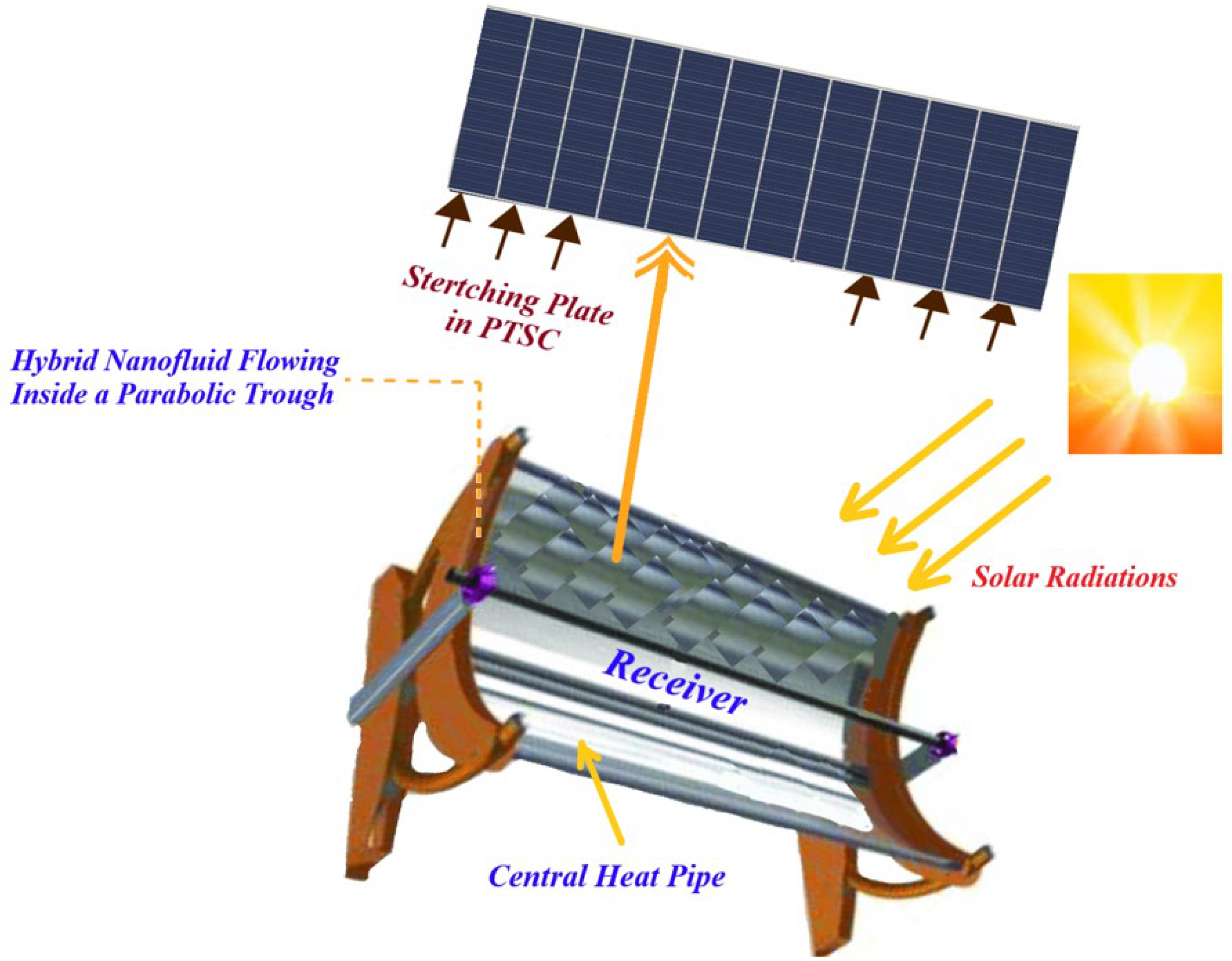
Figure 1 represents a PTSC diagram.
It is worth noting that the effects of an applied magneto transverse direction on the form factor and heat transmission characteristics of Newtonianism HBNF rotational flow on porous flat surfaces have never been studied in the literature when employing two types of nanomolecules, which we used for our study: copper (Cu) and alumina (Al2O3), with Newtonianism water (H2O) as the fluid. As a result, the purpose of this study is to provide scientific solutions to the following research issues:
  • To what extent does increasing rapidity outline the temperatures contour within the boundary-layer, drag force factor, and the quantity of Nusselt provided?
  • How do heat transfer rates alter with increasing the magnetization impact and nanoparticles volume fractions in hybridity and mono nanofluid dynamics?
  • What are the differences between the use of a hybrid nanofluid and a neutral nanofluid in terms of thermal and electrical conductivities?
  • To what extent does rotational motion affect the velocity patterns and heat transfer rates of the nanofluids that were used in the investigation.
  • Does the porosity of the surrounding medium as well as the permeability of surfaces have a role in changing the flow rapidity and heat transmission rates of the used nanofluids that were under study?

2. Mathematical Modelling

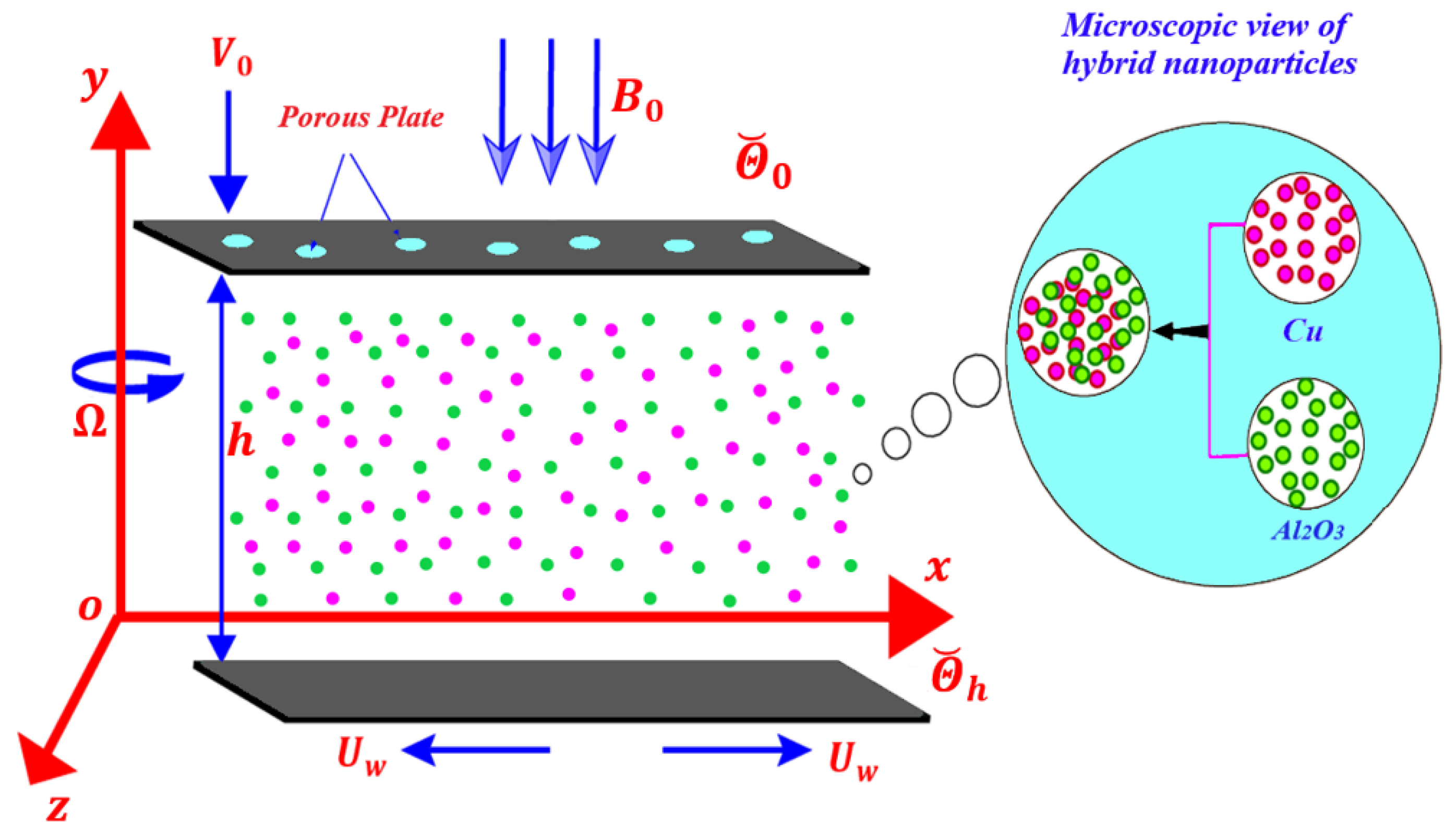
Consider the stable hybridity nanofluid flowing between two horizontal parallel similar surfaces whenever the nanoliquid and the plates rotate with an angular velocity Ω around the y axis normal to the plates. The x axis is parallel to the surface, the y axis is normal to it, and the z axis is normal to the x   y plane in a Cartesian coordinates system (see Figure 2). The plates may be found at y = 0 and y = h . Two equal and opposite pressures stretch the lower surface, keeping the location of the point (0, 0, 0) constant. This paper examined a three-dimensional continuous magneto-spin flow of HBNF (Cu-Al2O3/H2O) among 2-surfaces that were operating with angular speed Ω   0 ,   Ω , 0 under heat transmission. The bottom plate’s stretched speed is U w = a x   ( a > 0 ) , but the top surface has penetrability. The flow field’s speed is V = u , v , w . In the y axis path, a constant magneto field B 0 is used. An induced magnetic field is neglected when the magnetism Reynolds amount is assumed to be below. Figure 2 depicts the mathematical model of the flowing field as well as the coordinate system.
The conveyed relevant system of equalities for rotating flowing can be expressed as [53]:
V = 0 ,
ρ h b n f d V d t + 2 Ω × V + Ω × Ω × r = div   τ + J × B ,
( ρ C p ) h b n f V Θ ˘ = κ h b n f 2 Θ ˘ 1 ( ρ C p ) h b n f ( q r ) y q 1
in which q 1 is heat fluxing. CCM [15] allows one to write:
q 1 + λ * V q 1 q 1 V + V q 1 = k Θ ˘ .
The elements form of regulating model is offered as the subsequent [52]:
u x + v y = 0 ,
ρ h b n f u u x + v u y + 2 Ω w = p * * x + μ h b n f 2 u x 2 + 2 u y 2 σ h b n f B 0 2 u ,
ρ h b n f u v x + v v y = p * * y + μ h b n f 2 v x 2 + 2 v y 2 ,
ρ h b n f u w x + v w y 2 Ω u = μ h b n f 2 w x 2 + 2 w y 2 σ h b n f B 0 2 w ,
u Θ ˘ x + v Θ ˘ y = α h b n f 2 Θ ˘ x 2 + 2 Θ ˘ y 2 + 1 ( ρ C p ) h b n f 16 σ * Θ ˘ 3 3 k * 2 Θ ˘ y 2 λ * u u x Θ ˘ x + v v y Θ ˘ y λ * x Θ ˘ y + v u y Θ ˘ x + 2 u v 2 Θ ˘ x y + u 2 2 Θ ˘ x 2 + v 2 2 Θ ˘ y 2 ,
in which α h b n f = κ h b n f ( ρ C p ) h b n f signifies a thermal diffusion of HBNF and p * * = p Ω 2 x 2 2 signifies a changed pressure. Instead of Al2O3/H2O and Cu-Al2O3/H2O), the expressions are given in Table 1 and Table 2.
In the case of uniform suction/injection, the v rapidity element stays stable at a higher surface due to porosity. The temperature change is recognized through HBNF. An upper plate has heat Θ ˘ 0 and the bottom plate has heat Θ ˘ h such that Θ ˘ 0 < Θ ˘ h . The physical thermal characteristics of Al2O3, Cu, and H2O are described in Table 3.
The following are the destination constraints at the upper and lower plates:
at         y = 0 ,         u = U w = a x ,         v = 0 ,   w = 0 ,         Θ ˘ = Θ ˘ h , at         y = h ,         u = 0 ,         v = W 0 ,         w = 0 ,         Θ ˘ = Θ ˘ 0 ,
in which positive W 0 implies the suction and negative W 0 implies the injection at the upper wall. Consider similarity transformation [56] as:
u = a x f ς ,         v = a h f ς ,         w = a x g ς ,         θ ς = Θ ˘ Θ ˘ 0 Θ ˘ h Θ ˘ 0 ,         ς = y h .
The resulting nondimensional system of ODEs is offered by:
f i v D 1 ϕ 1 ϕ 2 f f f f 2 D 2 ϕ 1 ϕ 2 g D 1 D 3 ϕ 1 ϕ 5 f = 0 ,
g D 1 ϕ 1 ϕ 2 g f f g + 2 D 2 ϕ 1 ϕ 2 f D 1 D 3 ϕ 1 ϕ 5 g = 0 ,
1 + 4 3 N r ϕ 4 θ + P r D 1 ϕ 3 ϕ 4 f θ P r γ * ϕ 3 ϕ 4 f f θ + f 2 θ = 0 .
having the following non-dimensional endpoint conditions:
f = 0 ,         f = 1 ,         g = 0 ,         θ = 1   at   ς = 0 , f = S ,         g = 0 ,         f = 0 ,         θ = 0   at   ς = 1 .
The nondimensional factors that are associated with nondimensional formulas are stated as:
D 1 = a h 2 ν f         Reynolds     number ,         D 2 = Ω h 2 ν f         rotation     parameter ,       D 3 = σ f ρ f a B 0 2   Hartmann number ,           P r = μ f c f k f   Prandtl   number ,                   S = W 0 a h         suction / injection   parameter ,     N r = k * κ f 4 σ * T 3   radiation parameter , γ * = λ * a         thermal relaxation parameter .                                                                                                                
The frictional force factor C f and the Nusselt quantity N u x are given in dimensional form the next relationships [57]:
C f = 2 τ w ρ h b n f U w 2 ,                 N u x = x q w k h b n f Θ ˘ w Θ ˘ ,
in which τ w = μ h b n f u y signifies the shearing stress and q w = k h b n f Θ ˘ y denotes the heat fluxing at the surface. The dimensionless manner of Equation (17) via similarity transformations that were before declared in Equation (11) are expressed as follows:
C f R e x 1 / 2 = ϕ 2 ϕ 1 f 0 ,           R e x 1 / 2 N u x = θ 0 , C f R e x 1 / 2 = ϕ 2 ϕ 1 f 1 ,           R e x 1 / 2 N u x = θ 1 ,
in which R e x = U w x ν f expresses the Reynolds quantity.

3. Numerical Implementation

To solve the non-linear ODEs (12)–(14) concerning the endpoint condition (15), the Keller box method scheme [58,59] was used with the computational program MATLAB for varying values of the relevant aspects. The Keller box scheme’s step-by-step approach is depicted in a program flow chart (Figure 3):

3.1. Transformation of ODEs

Following the replacements have been implemented for transforming complex physical ODEs into first-order ODEs. ϖ r 1 , ϖ r 2 , ϖ r 3 , ϖ r 4 , ϖ r 5 , ϖ r 6 , ϖ r 7 , and ϖ r 8 are supplied as dependent variables as subsequent:
ϖ r 1 = f ,   ϖ r 2 = f ,   ϖ r 3 = f ,   ϖ r 4 = f ,   ϖ r 5 = g ,   ϖ r 6 = g , ϖ r 7 = θ ,   ϖ r 8 = θ .
d ϖ r 1 d ς = ϖ r 2 ,
d ϖ r 2 d ς = ϖ r 3 ,
d ϖ r 3 d ς = ϖ r 4 ,
d ϖ r 5 d ς = ϖ r 6 ,
d ϖ r 7 d ς = ϖ r 8 ,
d ϖ r 4 d ς ϕ 1 ϕ 2 D 1 ϖ r 2 ϖ r 3 + ϕ 1 ϕ 2 D 1 ϖ r 1 ϖ r 4 2 D 2 ϕ 1 ϕ 2 ϖ r 6 ϕ 1 ϕ 5 D 1 D 3 2 ϖ r 3 = 0 ,
d ϖ r 6 d ς ϕ 1 ϕ 2 D 1 ϖ r 2 ϖ r 5 + ϕ 1 ϕ 2 D 1 ϖ r 1 ϖ r 6 + 2 D 2 ϕ 1 ϕ 2 ϖ r 2 ϕ 1 ϕ 5 D 1 D 3 2 ϖ r 5 = 0 ,
1 + 4 3 N r ϕ 4 d ϖ r 8 d ς + P r D 1 ϕ 3 ϕ 4 ϖ r 1 ϖ r 8 P r γ * ϕ 3 ϕ 4 ϖ r 1 ϖ r 2 ϖ r 8 P r γ * ϕ 3 ϕ 4 ( ϖ r 1 ) 2 d ϖ r 8 d ς = 0 ,
ϖ r 1 0 = 0 ,   ϖ r 2 0 = 1 ,   ϖ r 5 0 = 0 ,   ϖ r 7 0 = 1 , ϖ r 1 1 = S ,   ϖ r 2 1 = 0 ,   ϖ r 5 1 = 0 ,   ϖ r 7 1 = 0 .

3.2. Domain Discretisation and Differences Equalities

The domain 0 ,   1 has been subdivided using uniform meshes and the subsequent griding nodes (Figure 4):
ς 0 = 0 ,   ς j = ς j 1 + Δ x j ,   j = 0 ,   1 ,   2 ,   3 ... , J ,         ς J = 1
where, Δ x j signifies a stride sizing. Equations (25)–(28) have been computed using center difference at the mid-points ς j 1 / 2 , as shown below:
( ϖ r 1 ) j ( ϖ r 1 ) j 1 = 0.5 Δ x j ( ( ϖ r 2 ) j + ϖ r 2 ) j 1 ,
( ϖ r 2 ) j ( ϖ r 2 ) j 1 = 0.5 Δ x j ( ( ϖ r 3 ) j + ϖ r 3 ) j 1 ,
( ϖ r 3 ) j ( ϖ r 3 ) j 1 = 0.5 Δ x j ( ( ϖ r 4 ) j + ϖ r 4 ) j 1 ,
( ϖ r 5 ) j ( ϖ r 5 ) j 1 = 0.5 Δ x j ( ( ϖ r 6 ) j + ϖ r 6 ) j 1 ,
( ϖ r 7 ) j ( ϖ r 7 ) j 1 = 0.5 Δ x j ( ( ϖ r 8 ) j + ϖ r 8 ) j 1 ,
( ( ϖ r 4 ) j ϖ r 4 ) j 1 Δ x j ϕ 1 ϕ 2 D 1 ( ( ϖ r 2 ) j + ϖ r 2 ) j 1 ( ( ϖ r 3 ) j + ϖ r 3 ) j 1 + Δ x j ϕ 1 ϕ 2 D 1 ( ( ϖ r 1 ) j + ϖ r 1 ) j 1 ϖ r 1 ( ( ϖ r 4 ) j + ϖ r 4 ) j 1 2 Δ x j D 2 ϕ 1 ϕ 2 ( ( ϖ r 6 ) j + ϖ r 6 ) j 1 Δ x j ϕ 1 ϕ 5 D 1 D 3 2 ( ( ϖ r 3 ) j + ϖ r 3 ) j 1 = 0 ,
( ( ϖ r 6 ) j ϖ r 6 ) j 1 Δ x j ϕ 1 ϕ 2 D 1 ( ( ϖ r 2 ) j + ϖ r 2 ) j 1 ( ( ϖ r 5 ) j + ϖ r 5 ) j 1 + Δ x j ϕ 1 ϕ 2 D 1 ( ( ϖ r 1 ) j + ϖ r 1 ) j 1 ( ( ϖ r 6 ) j + ϖ r 6 ) j 1 + 2 Δ x j D 2 ϕ 1 ϕ 2 ( ( ϖ r 2 ) j + ϖ r 2 ) j 1 Δ x j ϕ 1 ϕ 5 D 1 D 3 2 ( ( ϖ r 5 ) j + ϖ r 5 ) j 1 = 0 , ,
1 + 4 3 N r ϕ 4 ( ( ϖ r 8 ) j ϖ r 8 ) j 1 + Δ x j P r D 1 ϕ 3 ϕ 4 ( ( ϖ r 1 ) j + ϖ r 1 ) j 1 ( ( ϖ r 8 ) j + ϖ r 8 ) j 1 Δ x j γ * P r ϕ 3 8 ϕ 4 ( ( ϖ r 1 ) j + ϖ r 1 ) j 1 ( ( ϖ r 2 ) j + ϖ r 2 ) j 1 ( ( ϖ r 8 ) j + ϖ r 8 ) j 1 Δ x j γ * P r ϕ 3 4 ϕ 4 ( ( ϖ r 1 ) j + ( ϖ r 1 ) j 1 ) 2 ( ( ϖ r 8 ) j ϖ r 8 ) j 1 = 0 .

3.3. Newtonian Linearizing

The overhead equalities scheme (29)–(36) is linearized using the Newtonianism linearizing procedure with the subsequent replacement:
( ϖ r 1 ) j n + 1 = ( ϖ r 1 ) j n + δ ( ϖ r 1 ) j n ,         ( ϖ r 2 ) j n + 1 = ( ϖ r 2 ) j n + δ ( ϖ r 2 ) j n , ( ϖ r 3 ) j n + 1 = ( ϖ r 3 ) j n + δ ( ϖ r 3 ) j n ,         ( ϖ r 4 ) j n + 1 = ( ϖ r 4 ) j n + δ ( ϖ r 4 ) j n , ( ϖ r 5 ) j n + 1 = ( ϖ r 5 ) j n + δ ( ϖ r 5 ) j n ,         ( ϖ r 6 ) j n + 1 = ( ϖ r 6 ) j n + δ ( ϖ r 6 ) j n , ( ϖ r 7 ) j n + 1 = ( ϖ r 7 ) j n + δ ( ϖ r 7 ) j n ,         ( ϖ r 7 ) j n + 1 = ( ϖ r 7 ) j n + δ ( ϖ r 7 ) j n ,
Substitute the expressions that were obtained in (28)–(35), dropping the squares and larger degree terms of δ , the subsequent group of equalities is accomplished:
( ( δ ϖ r 1 ) j   δ ϖ r 1 ) j 1 0.5 Δ x j ( ( δ ϖ r 2 ) j   + δ ϖ r 2 ) j 1 = ( r 1 ) j ,
( ( δ ϖ r 2 ) j   δ ϖ r 2 ) j 1 0.5 Δ x j ( ( δ ϖ r 3 ) j   + δ ϖ r 3 ) j 1 = ( r 2 ) j ,
( ( δ ϖ r 3 ) j   δ ϖ r 3 ) j 1 0.5 Δ x j ( ( δ ϖ r 4 ) j   + δ ϖ r 4 ) j 1 = ( r 3 ) j ,
( ( δ ϖ r 5 ) j   δ ϖ r 5 ) j 1 0.5 Δ x j ( ( δ ϖ r 6 ) j   + δ ϖ r 6 ) j 1 = ( r 4 ) j ,
( ( δ ϖ r 7 ) j   δ ϖ r 7 ) j 1 0.5 Δ x j ( ( δ ϖ r 8 ) j   + δ ϖ r 8 ) j 1 = ( r 5 ) j ,
( η 1 ) j ( δ ϖ r 1 ) j + ( η 2 ) j ( δ ϖ r 1 ) j 1 + ( η 3 ) j ( δ ϖ r 2 ) j + ( η 4 ) j ( δ ϖ r 2 ) j 1 + ( η 5 ) j ( δ ϖ r 3 ) j + ( η 6 ) j ( δ ϖ r 3 ) j 1 + ( η 7 ) j ( δ ϖ r 4 ) j + ( η 8 ) j ( δ ϖ r 4 ) j 1 + ( η 9 ) j ( δ ϖ r 6 ) j + ( η 10 ) j ( δ ϖ r 6 ) j 1 = ( r 6 ) j ,
( ε 1 ) j ( δ ϖ r 1 ) j + ( ε 2 ) j ( δ ϖ r 1 ) j 1 + ( ε 3 ) j ( δ ϖ r 2 ) j + ( ε 4 ) j ( δ ϖ r 2 ) j 1 + ( ε 5 ) j ( δ ϖ r 5 ) j + ( ε 6 ) j ( δ ϖ r 5 ) j 1 + ( ε 7 ) j ( δ ϖ r 6 ) j + ( ε 8 ) j ( δ ϖ r 6 ) j 1 = ( r 7 ) j ,
( λ 1 ) j ( δ ϖ r 1 ) j + ( λ 2 ) j ( δ ϖ r 1 ) j 1 + ( λ 3 ) j ( δ ϖ r 2 ) j + ( λ 4 ) j ( δ ϖ r 2 ) j 1 + ( λ 5 ) j ( δ ϖ r 8 ) j + ( λ 6 ) j ( δ ϖ r 8 ) j 1 = ( r 8 ) j ,
where:
( η 1 ) j = Δ x j D 1 ϕ 1 ϕ 2 ( ( ϖ r 4 ) j + ϖ r 4 ) j 1 4 = ( η 2 ) j , ( η 3 ) j = Δ x j ϕ 1 ϕ 2 ( ( ϖ r 4 ) j + ϖ r 4 ) j 1 4 = ( η 4 ) j , ( η 5 ) j = 1 2 Δ x j D 1 D 3 2 ϕ 1 ϕ 5 Δ x j ϕ 1 ϕ 2 ( ( ϖ r 2 ) j + ϖ r 2 ) j 1 4 = ( η 6 ) j , ( η 7 ) j = 1 + Δ x j ϕ 1 ϕ 2 ( ( ϖ r 1 ) j + ϖ r 1 ) j 1 4 , ( η 8 ) j = 1 + Δ x j ϕ 1 ϕ 2 ( ( ϖ r 1 ) j + ϖ r 1 ) j 1 4 , ( η 9 ) j = Δ x j D 2 ϕ 1 ϕ 2 , ( η 10 ) j = Δ x j D 2 ϕ 1 ϕ 2 , ( r 6 ) j = 1 2 Δ x j D 1 D 3 2 ϕ 1 ϕ 5 ( ( ϖ r 3 ) j + ϖ r 3 ) j 1 + 1 4 Δ x j ϕ 1 ϕ 2 ( ( ϖ r 2 ) j + ϖ r 2 ) j 1 ( ( ϖ r 3 ) j + ϖ r 3 ) j 1 1 4 Δ x j D 1 ϕ 1 ϕ 2 ( ( ϖ r 1 ) j + ϖ r 1 ) j 1 ( ( ϖ r 4 ) j + ϖ r 4 ) j 1 + Δ x j D 2 D 3 2 ϕ 1 ϕ 2 ( ( ϖ r 6 ) j + ϖ r 6 ) j 1 ,
( ε 1 ) j = Δ x j D 1 ϕ 1 ϕ 2 ( ( ϖ r 6 ) j + ϖ r 6 ) j 1 4 = ( ε 2 ) j , ( ε 3 ) j = Δ x j D 2 ϕ 1 ϕ 2 Δ x j D 1 ϕ 1 ϕ 2 ( ( ϖ r 5 ) j + ϖ r 5 ) j 1 4 = ( ε 2 ) j , ( ε 5 ) j = 1 2 Δ x j D 1 D 3 2 ϕ 1 ϕ 5 Δ x j D 1 ϕ 1 ϕ 2 ( ( ϖ r 2 ) j + ϖ r 2 ) j 1 4 = ( ε 6 ) j , ( ε 7 ) j = 1 + Δ x j D 1 ϕ 1 ϕ 2 ( ( ϖ r 1 ) j + ϖ r 1 ) j 1 4 , ( ε 8 ) j = 1 + Δ x j D 1 ϕ 1 ϕ 2 ( ( ϖ r 1 ) j + ϖ r 1 ) j 1 4 , ( r 7 ) j = Δ x j D 2 ϕ 1 ϕ 2 ( ( ϖ r 2 ) j + ϖ r 2 ) j 1 + 1 2 Δ x j D 1 D 3 2 ϕ 1 ϕ 5 ( ( ϖ r 5 ) j + ϖ r 5 ) j 1 + 1 4 Δ x j D 1 ϕ 1 ϕ 2 ( ( ϖ r 2 ) j + ϖ r 2 ) j 1 ( ( ϖ r 5 ) j + ϖ r 5 ) j 1 ( ( ϖ r 6 ) j ϖ r 6 ) j 1 1 4 Δ x j D 1 ϕ 1 ϕ 2 ( ( ϖ r 1 ) j + ϖ r 1 ) j 1 ( ( ϖ r 6 ) j + ϖ r 6 ) j 1 ,
( λ 1 ) j = Δ x j D 1 ϕ 3 P r ϕ 4 ( ( ϖ r 8 ) j + ϖ r 8 ) j 1 4 1 2 γ * P r D 1 ϕ 3 ϕ 4 ( ( ϖ r 8 ) j ϖ r 8 ) j 1 ( ( ϖ r 1 ) j + ϖ r 1 ) j 1 1 8 Δ x j γ * P r ϕ 3 ϕ 4 ( ( ϖ r 8 ) j + ϖ r 8 ) j 1 ( ( ϖ r 2 ) j + ϖ r 2 ) j 1 = ( λ 2 ) j , ( λ 3 ) j = Δ x j γ * P r ϕ 3 ϕ 4 ( ( ϖ r 1 ) j + ϖ r 1 ) j 1 ( ( ϖ r 8 ) j + ϖ r 8 ) j 1 8 = ( λ 4 ) j , ( λ 5 ) j = 1 + 4 3 N r ϕ 4 + Δ x j D 1 ϕ 3 P r ϕ 4 ( ( ϖ r 1 ) j + ϖ r 1 ) j 1 4 Δ x j P r γ * ϕ 3 8 ϕ 4 ( ( ϖ r 1 ) j + ( ϖ r 1 ) j 1 ) 2 Δ x j P r γ * ϕ 3 8 ϕ 4 ( ( ϖ r 1 ) j + ϖ r 1 ) j 1 ( ( ϖ r 8 ) j + ϖ r 8 ) j 1 8 , ( λ 6 ) j = 1 + 4 3 N r ϕ 4 + Δ x j D 1 ϕ 3 P r ϕ 4 ( ( ϖ r 1 ) j + ϖ r 1 ) j 1 4 Δ x j P r γ * ϕ 3 8 ϕ 4 ( ( ϖ r 1 ) j + ( ϖ r 1 ) j 1 ) 2 Δ x j P r γ * ϕ 3 8 ϕ 4 ( ( ϖ r 1 ) j + ϖ r 1 ) j 1 ( ( ϖ r 8 ) j + ϖ r 8 ) j 1 8 , ( r 8 ) j = 1 + 4 3 N r ϕ 4 ( ( ϖ r 8 ) j ϖ r 8 ) j 1 Δ x j P r D 1 ϕ 3 ϕ 4 ( ( ϖ r 1 ) j + ϖ r 1 ) j 1 ( ( ϖ r 8 ) j + ϖ r 8 ) j 1 + Δ x j P r γ * ϕ 3 8 ϕ 4 ( ( ϖ r 1 ) j + ϖ r 1 ) j 1 ( ( ϖ r 2 ) j + ϖ r 2 ) j 1 ( ( ϖ r 8 ) j + ϖ r 8 ) j 1 + Δ x j γ * P r ϕ 3 4 ϕ 4 ( ( ϖ r 1 ) j + ( ϖ r 1 ) j 1 ) 2 ( ( ϖ r 8 ) j ϖ r 8 ) j 1 .

3.4. Blocking Tridiagonal Construction

Following that, the linear structure has the blocking tridiagonal form that is shown below:
A δ = R ,
hence:
A = A 1   C 1   A 2   C 2   B J 1   A J 1   C J 1   B J   A J   ,   δ = δ 1 and     R = R 1 .
where the elements that are described in Equation (52) are:
A 1 = 3 p t 0 0 0 1 0 0 0 0 0.5 Δ x 1 0 0 0 0.5 Δ x 1 0 0 0 1 0.5 Δ x 1 0 0 1 0.5 Δ x 1 0 0 0 0 0.5 Δ x 1 0 0 0 0.5 Δ x 1 0 0 0 0 0.5 Δ x 1 0 0 0 0.5 Δ x 1 η 6 1 η 8 1 η 10 1 0 η 5 1 η 7 1 η 9 1 0 0 0 ε 8 1 0 0 0 ε 7 1 0 0 0 0 λ 4 1 0 0 0 λ 3 1 ,
A j = 3 p t 1 0.5 Δ x j 0 0 0 0 0 0 0 1 0 0 0.5 Δ x j 0 0 0 0 0 0 0 1 0.5 Δ x j 0 0 0 0 1 0 0 0 0.5 Δ x j 0 0 0 0 1 0 0 0 0.5 Δ x 1 η 2 j η 4 j 0 0 η 5 j η 7 j η 9 j 0 ε 2 j ε 4 j ε 6 j 0 0 0 ε 7 j 0 λ 2 j 0 0 0 0 0 0 λ 3 j , 2 j J
B j = 10 p t 0 0 0 0 0 0 0 0 0 0 0 0 0.5 Δ x j 0 0 0 0 0 0 0 1 0.5 Δ x j 0 0 0 0 0 0 0 0 0.5 Δ x j 0 0 0 0 0 0 0 0 0.5 Δ x 1 0 0 0 0 η 6 j η 8 j η 10 j 0 0 0 0 0 0 0 ε 8 j 0 0 0 0 0 0 0 0 λ 4 j , 2 j J
[ C j ] = 8 p t [ 0 0.5 Δ x j 0 0 0 0 0 0 0 1 0 0 0 0 0 0 0 0 0 0 0 0 0 0 0 1 0 0 0 0 0 0 0 0 1 0 0 0 0 ( η 1 ) j ( η 3 ) j 0 0 0 0 0 0 ( ε 1 ) j ( ε 3 ) j ( ε 5 ) j 0 0 0 0 0 ( λ 1 ) j 0 0 0 0 0 0 0 ] 1 j J 1
by factorizing A
A = L U ,
where
L = [ [ α 1   ] [ α 2   ] [ α J 1 ] [ B J   ] [ α J   ] ] , U = [ [ I ] [ Γ 1   ] [ I ] [ Γ 2   ] [ I ] [ Γ J 1   ] [ I ] ] ,
An overall volume of a blocking array A is J × J , all supervector blocking volume is 8 × 8. An identity column vector I with order eight. For a solving of δ , an LU deconstruction strategy is being used. For evaluating the netting volume of Δ x j = 1 × 10 2 is determined to have been suitable, and the findings are obtained with an average inaccuracy of 10−6.

4. Coding Authentication

To demonstrate the accuracy of the provided KBM solutions, we evaluated several of our findings with the observations of Ref. [56] for θ 0 in the status of diverse amounts of suction factor S while holding the other variables constant. The acquired findings are highly exact and genuine, demonstrating the existing computational system is very reliable in the conditions of computational analysis (Table 4).

5. Results and Discussions

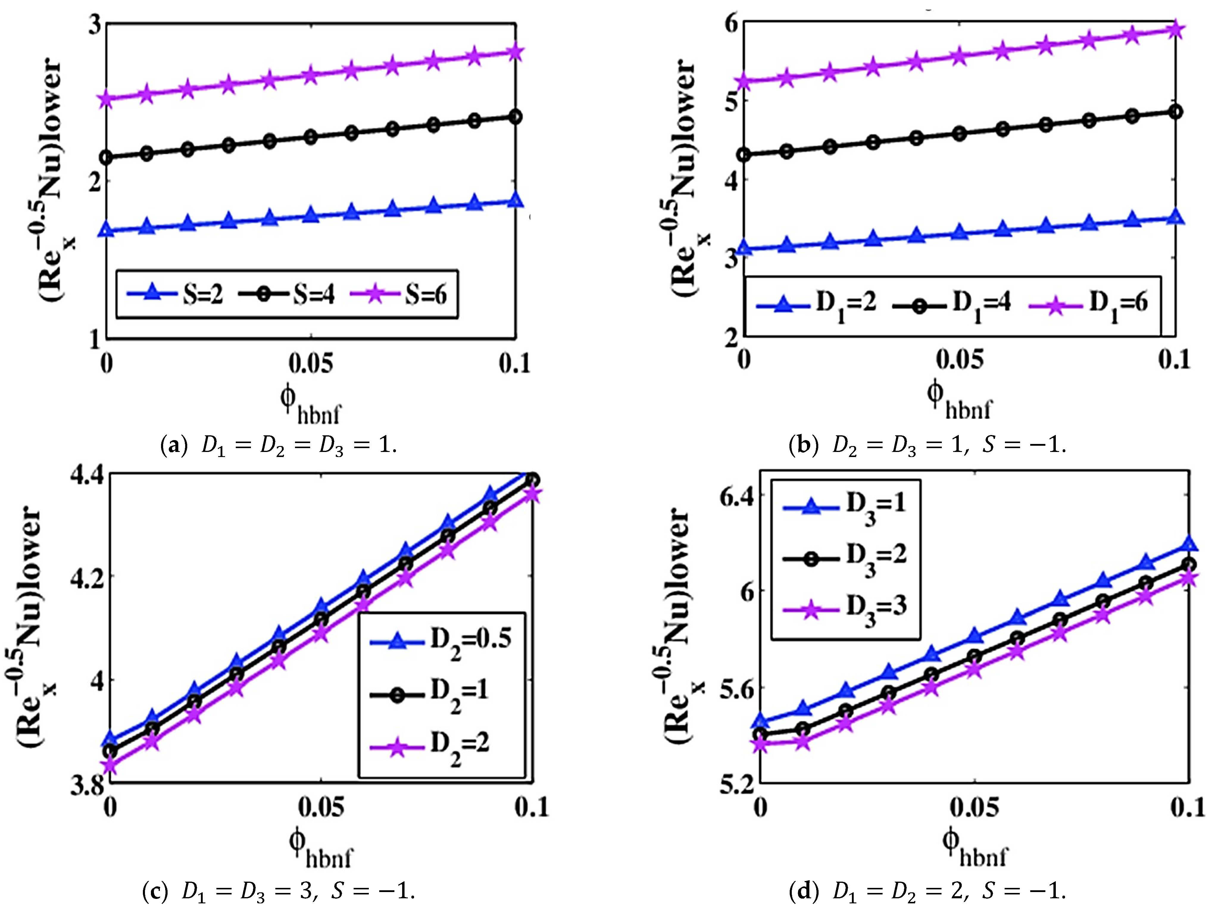
The current section is dedicated to analyzing the influence of varied dimensionless parameters on speed, rotational, and energy fields. The impact of the nanoparticles fractional size on wall frictional factor and RHT are numerically calculated and exhibited in tabular and graph structures.
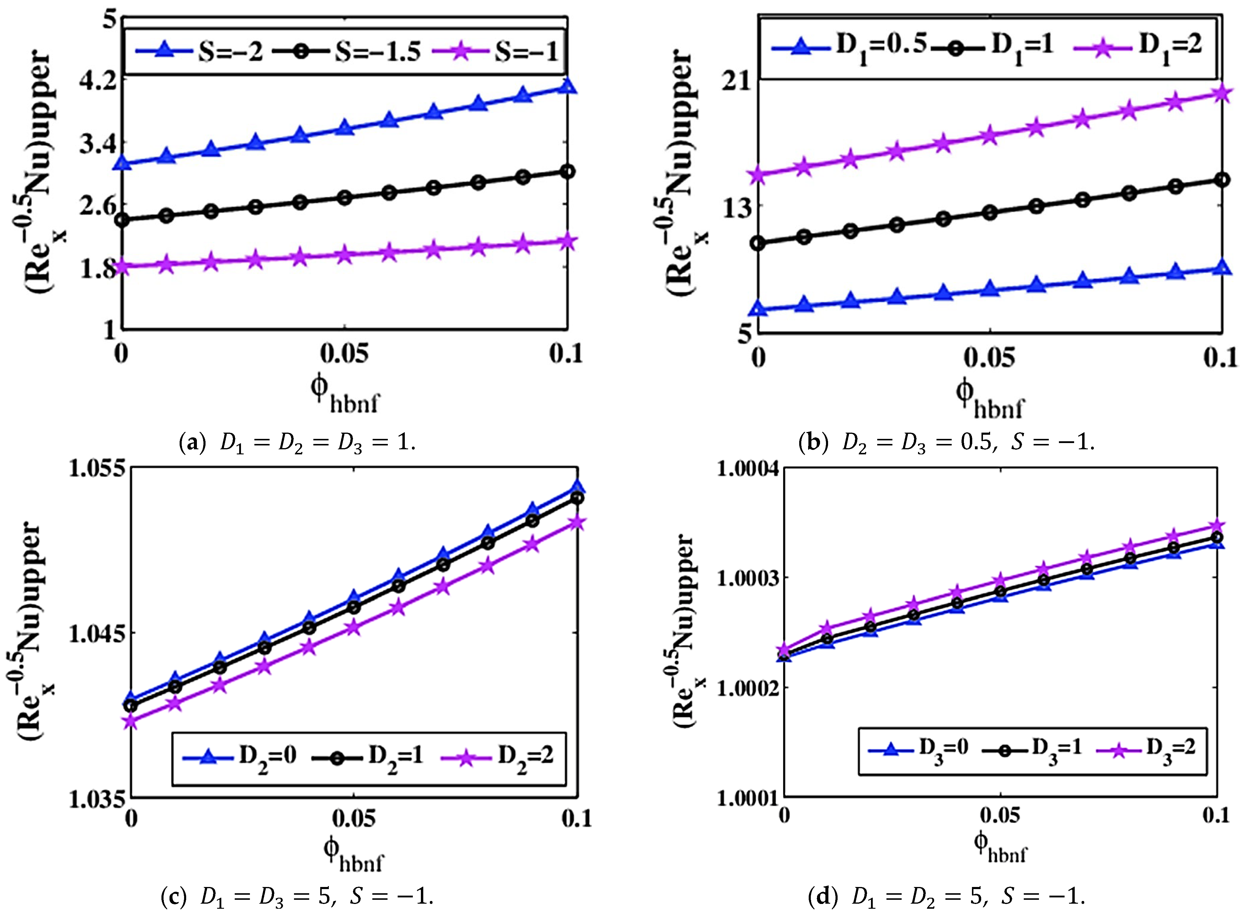
Table 5 reflects the impression of distinguished amounts of the fractional size of the nanomolecules on the wall frictional factor in the situation of Al2O3/H2O NF and Cu-Al2O3/H2O HBNF, respectively. It is extremely obvious that an amplification in the nanoparticles fractional size reduces a wall frictional force. The consistency of NF lessens by the virtue of growth of ϕ A retards the NF rapidity. The wall frictional factor increases at low plate surface ς = 0 in contrast to a higher stretchy plate ς = 1 . The NF rapidity reduces the amount of fluid traveling away from the bottom plate. The wall frictional force of Al2O3/H2O MNF exhibits progressive behavior at ς = 0 when compared to Cu-Al2O3/H2O HBNF, and the frictional force of stretched plate is located at ς = 1 .
Table 6 sketched the influence of ϕ A on N u x . The insertion of a mix of nanomolecules Cu-Al2O3 in the base liquid magnifies the RHT in comparison to the Al2O3/H2O-based nanofluid. The heat transmission is much better at the lower plate at ς = 0 in comparison to the plate that is located at ς = 1 . A conducting of the fluid is enhanced with hybridized nanomolecules. Hybrid nanoparticles Cu-Al2O3 are considered the best thermal conductor in contrast to Al2O3 nanoparticles based on the purpose of heat transfer. Likewise, the amplifying comportment of average heat transmission in Table 4 will go ahead to improve the performance and efficacy of PTSC. A thickener of the thermal bounder-layer augments as the temperature amplifies.
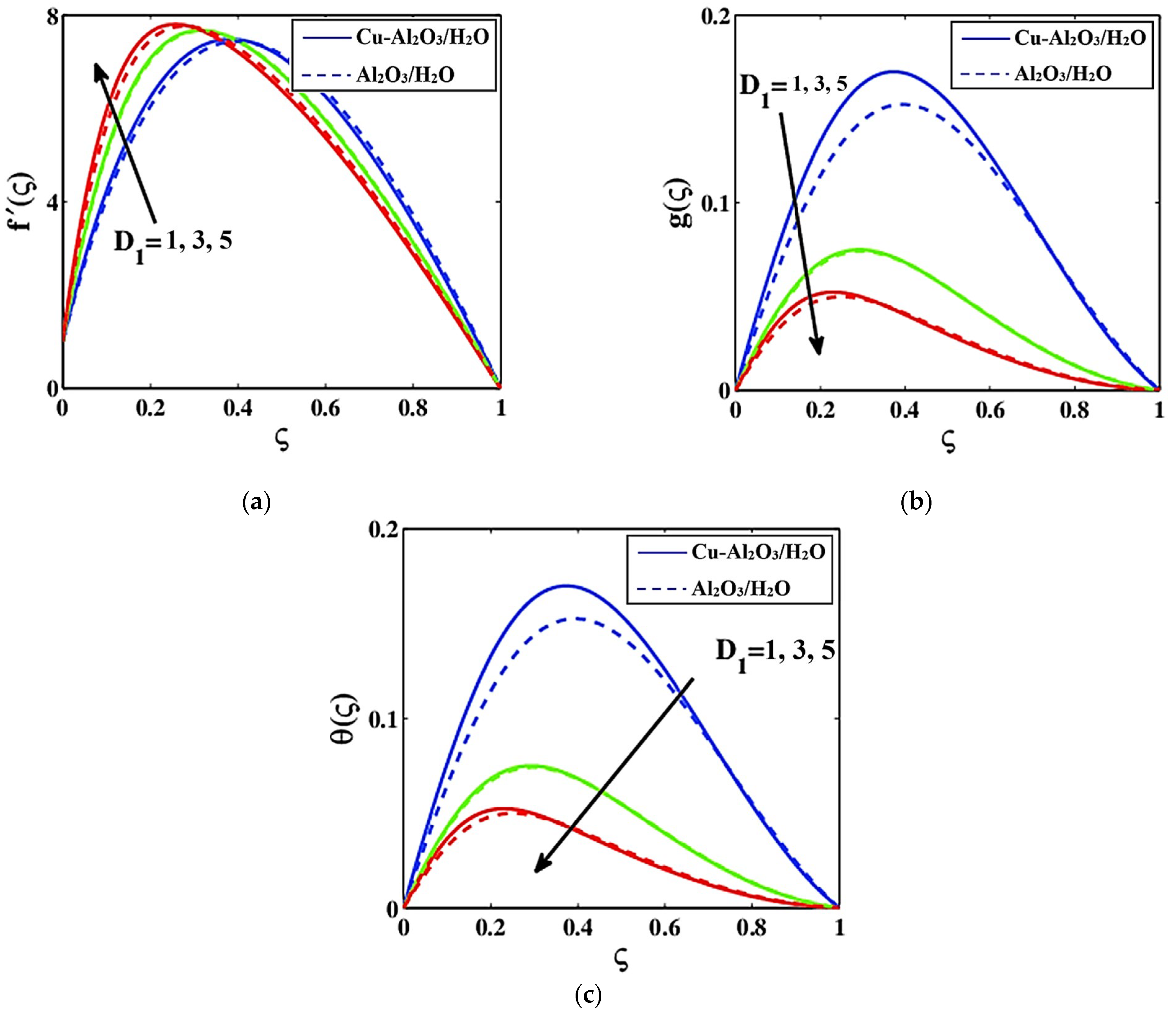
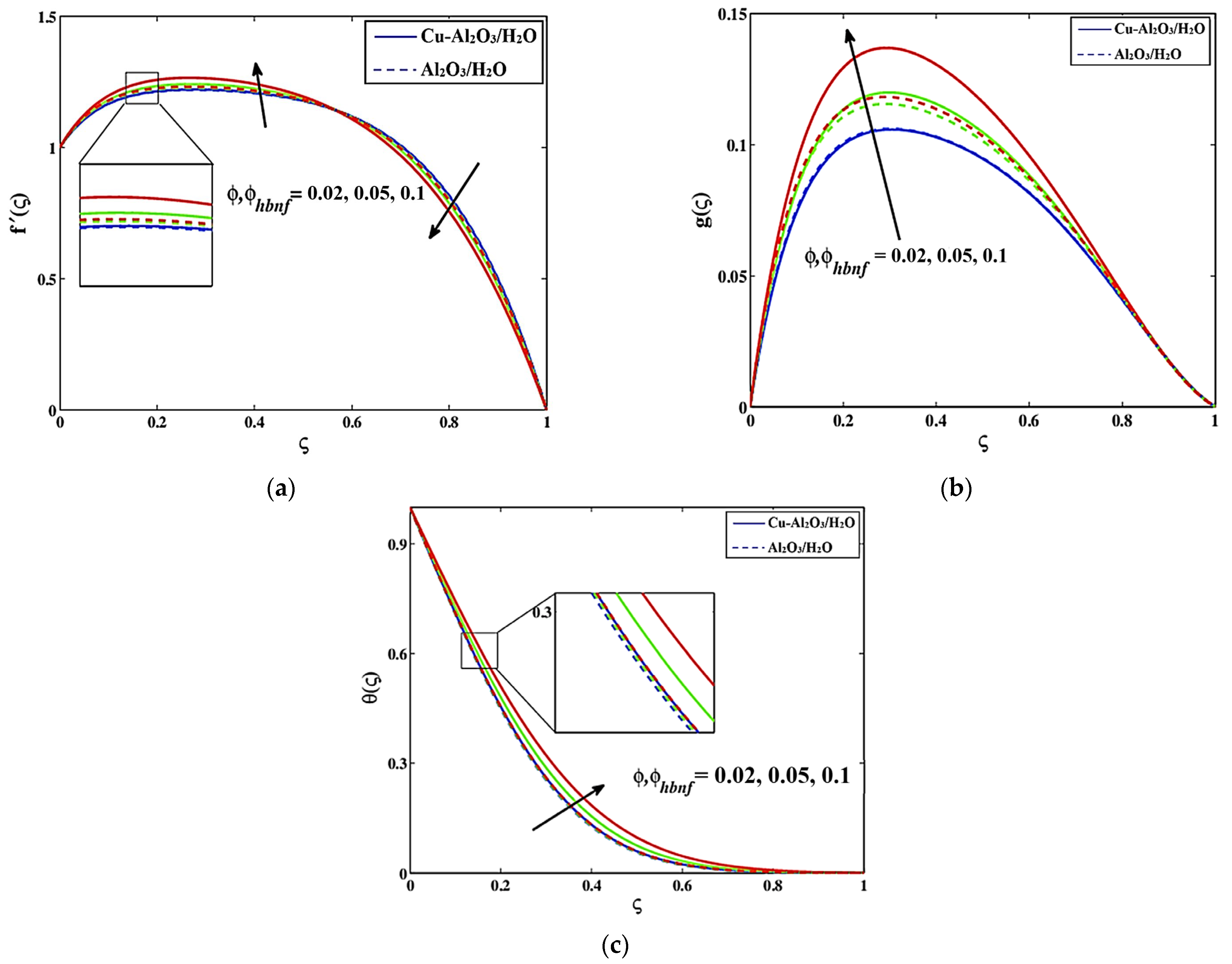
Figure 5a–c display an influence of the fractional size of nanomolecules factors ϕ and ϕ h b n f of traditional and HBNFs on the velocities f and g ς and the temperature outline θ ς , respectively. It is noted that a magnification in ϕ amplifies the consistency of the nanoparticles. The viscidness of a liquid escalates due to an augmentation in ϕ which impedes the movement of NF and a thickening of a motion boundary-layer too, and due to this, f drops. An effect of nanomolecules concentricity ϕ on the microrotation field g η is interpreted in Figure 5b. It manifests that enlargement in ϕ expands g ς . Physically, a positive alteration in ϕ topples the rotating percentage via a sheet enlarging rate and mostly supports less opposition to NF flow via the expandable plate. Intriguingly, the oscillating movement of the liquid is amplified as a result of magnifying ϕ quantities, which raises g ς . The temperature of NF is proportional to ϕ . The temperature boundary-layer thickener improves as a result of enrichment in ϕ quantities. More heat is created within, escalating the heat transfer phenomena and temperature domain θ ς . Physically, the reason for the increase in the speed, especially near the boundary layer, as well as the temperature is that the increase in nanoparticles improves the thermal conducting, which increases the movement of particles within the fluid, and thus boosts the random movement in it.
Figure 6a–c exhibit the influence of sucking factor S on f , g ς , and θ ς . The speed of the liquid increases due to an incremental change in S . The speed of the fluid accelerates as a result of enrichment in S , which uplifts f . The rotating influence of the liquid augmentation is due to a development in a suction factor. In the scenario of suction, the fluid that is present at free-streaming platter constraints is near a surface. Due to the thickener, the temperature boundary-layer diminishes and RHT decreases owing to magnification in S . From these graphs, it is clear that Cu-Al2O3/H2O HBNF has superior thermal conductance in comparison to Al2O3/H2O MNF. This is because the heat source works to increase the random motion of particles in the fluid which acts to enhance the rapidity of the nanofluid.
Figure 7a–c expose the influence of Reynold’s number D 1 on f , g ς , and θ ς , respectively. It is noted that the inertial powers topple the viscidness forces on the behalf of augmentation in D 1 . The viscous powers decrease by the virtue of an increase in D 1 . A thickener of the momentum boundary-layer increases, and the NF consistency decreases as D 1 increases, which reduces NF movement and flow rapidity f ς . A progressive change in D 1 reduces the NF angular momentum and provides greater resistance to the NF that is moving. A steady shift in D 1 alters the NF behavior from stable to unstable, and the rotating impact reduces and devalued g ς . The viscidity of the material is proportional to θ ς . It is obvious that increasing D 1 reduces the NF viscidness, which raises the temperature. The thickening of the temperature boundary-layer besides heat transmission increases by the advantage of magnification in D 1 . The physical reason for this is that D 1 is inversely proportional with ν f . Whilst D 1 boosts that means, the viscidity diminishes which means that the rapidity is improved, and the temperature is reduced.
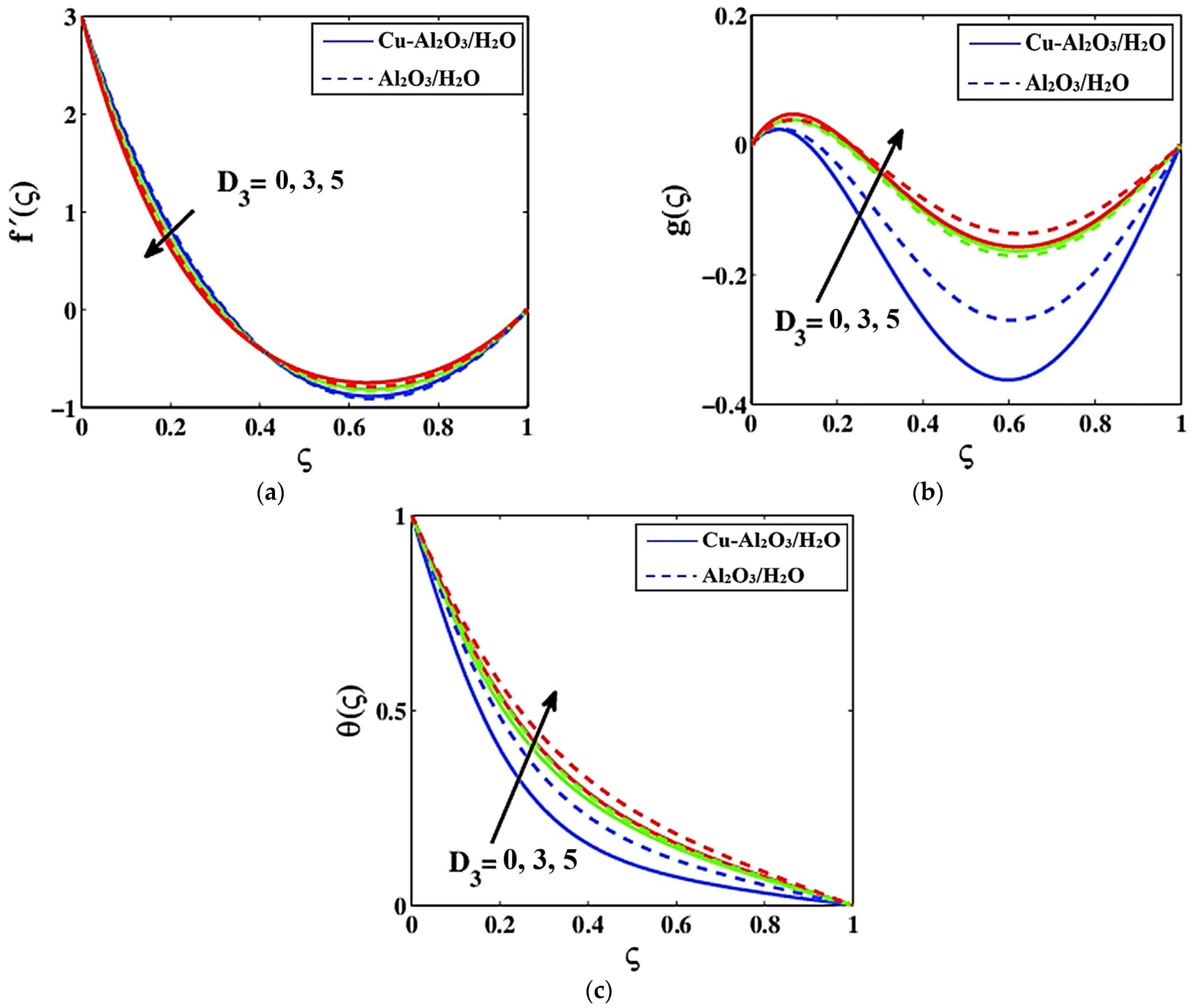
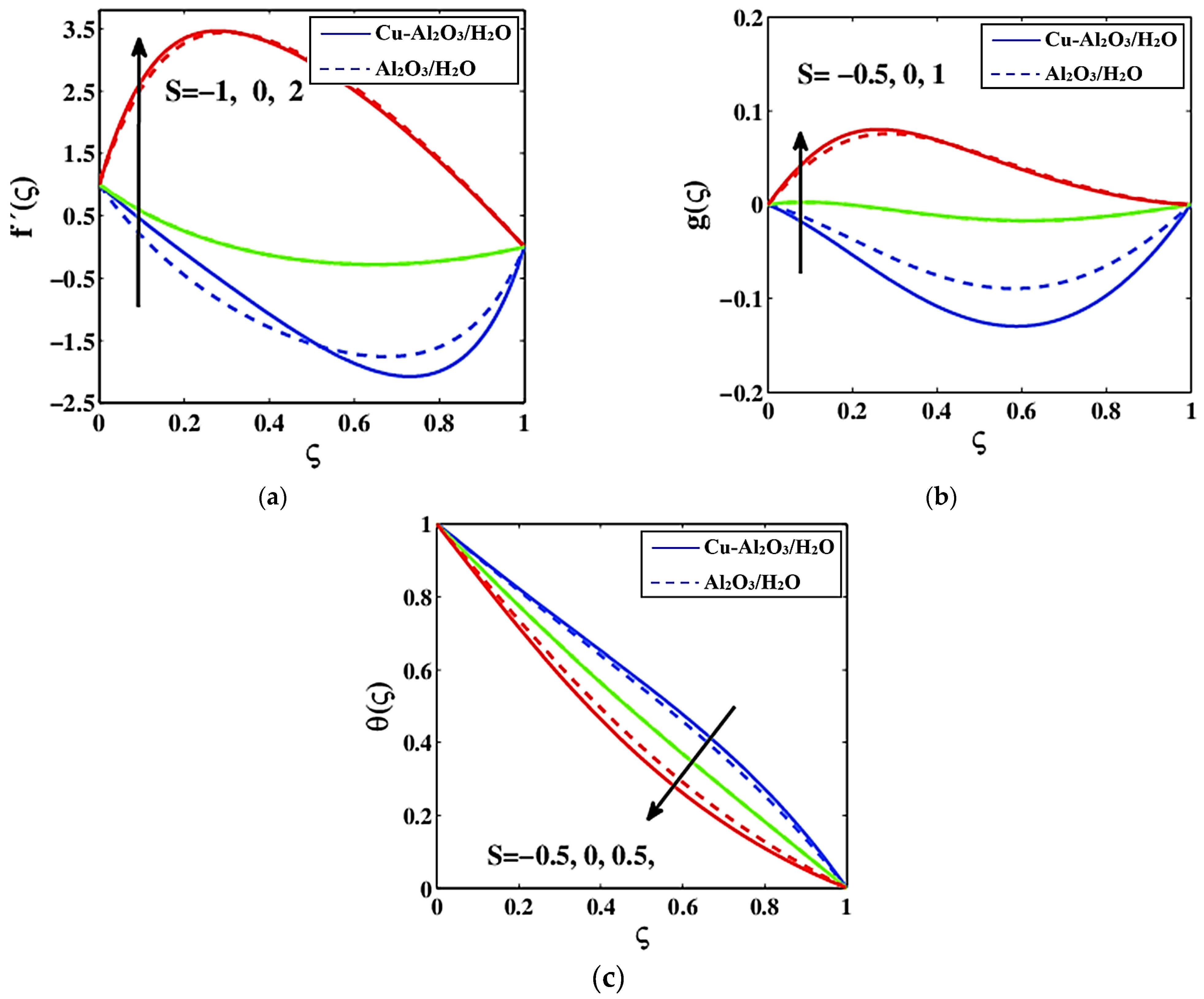
The influence of the rotation parameter D 2 on f , g η as well as θ η are displayed in Figure 8a–c, which indicate that a fortification in D 2 lessens f then enriches g ς and θ ς . It is discovered that the rotational rate exceeds the stretchable rate and, as a result, brings additional restrictions to the NF flowing movement, thus slowing the NF rapidity f ς . The NF’s rotating quickness develops for a progressive shift in D 2 , which raises g ς . The apparent viscidity declines due to a fortifying in D 2 that amplifies the temperature outline. It has been shown that heat transfer is considerably better in Cu-Al2O3/H2O HBNF than in Al2O3/H2O MNF. The thermal conductivity and thermal boundary-layer thickener of HBNF are elevated by hybridized nanomolecules.
Figure 9a–c emphasize the performing of electrically-conducting liquid magneto parameter D 3 f , g ς , and θ ς . An improvement shift in D 3 devalues the liquid rapidity. It is empirically validated that an electrical current in the occurrence of magnetism force releases a force called Lorentz forces. This Lorentz power is basic and offers endurance to a liquid flowing action. The speed of a liquid retards and is unsettled to an improvement shift in D 3 which reduces the thickener in terms of impetus boundary-layer also. Additionally, a magnification in D 3 provides elevated friction effects that have the capacity to contract the liquid rapidity and lessen the nanoliquid rotating occurrence g ς . It is remarkable that a non-negative shift in D 3 releases a powerful Lorentz effect that ultimately magnifies RHT. The temperature boundary-layer thickening improves in a state of stronger Lorentz powers. HBNF delivers better heat and amplifies the temperature much better in contrast to a Al2O3 nanoparticles-based fluid. The effects of N r , γ * , and P r on the thermal field are determined in Figure 10a–c for the case of hybrid nanoparticles and conventional nanoparticles. For increasing N r , the temperature θ gets augmented for Cu-Al2O3/H2O as well as for Al2O3/H2O along with the thermal boundary-layer. Physically, the enlargement in the thermal temperature profile is because of the heat transfer to fluid mixture particles by a boost in N r . The temperature profile for different γ * for Cu-Al2O3/H2O and Al2O3/H2O are displayed in 
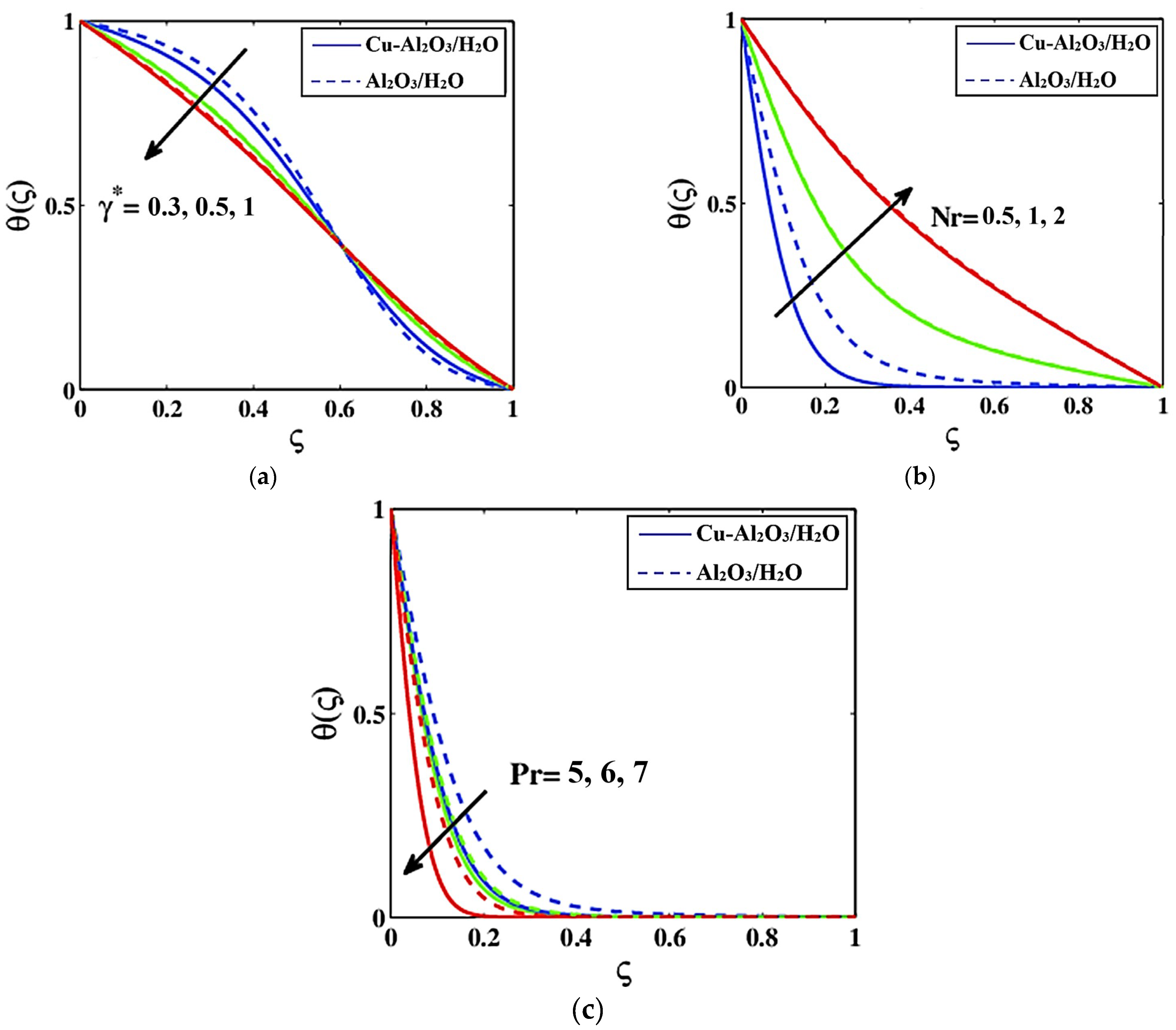
Figure 10b. The increase in γ * diminishes the temperature field for both the nanomaterial and the hybrid nanomaterial. This is based on the fact that as γ * increases, material particles need additional time to transmit the energy to their nearby molecules. As for greater amounts of γ * , the fluid mixture demonstrates a non-conducting behavior. An improvement shift in P r denigrates NF temperature. Thermal diffusivity shows dominating behavior for P r > 1 which leads to a reduction in the temperature profile.
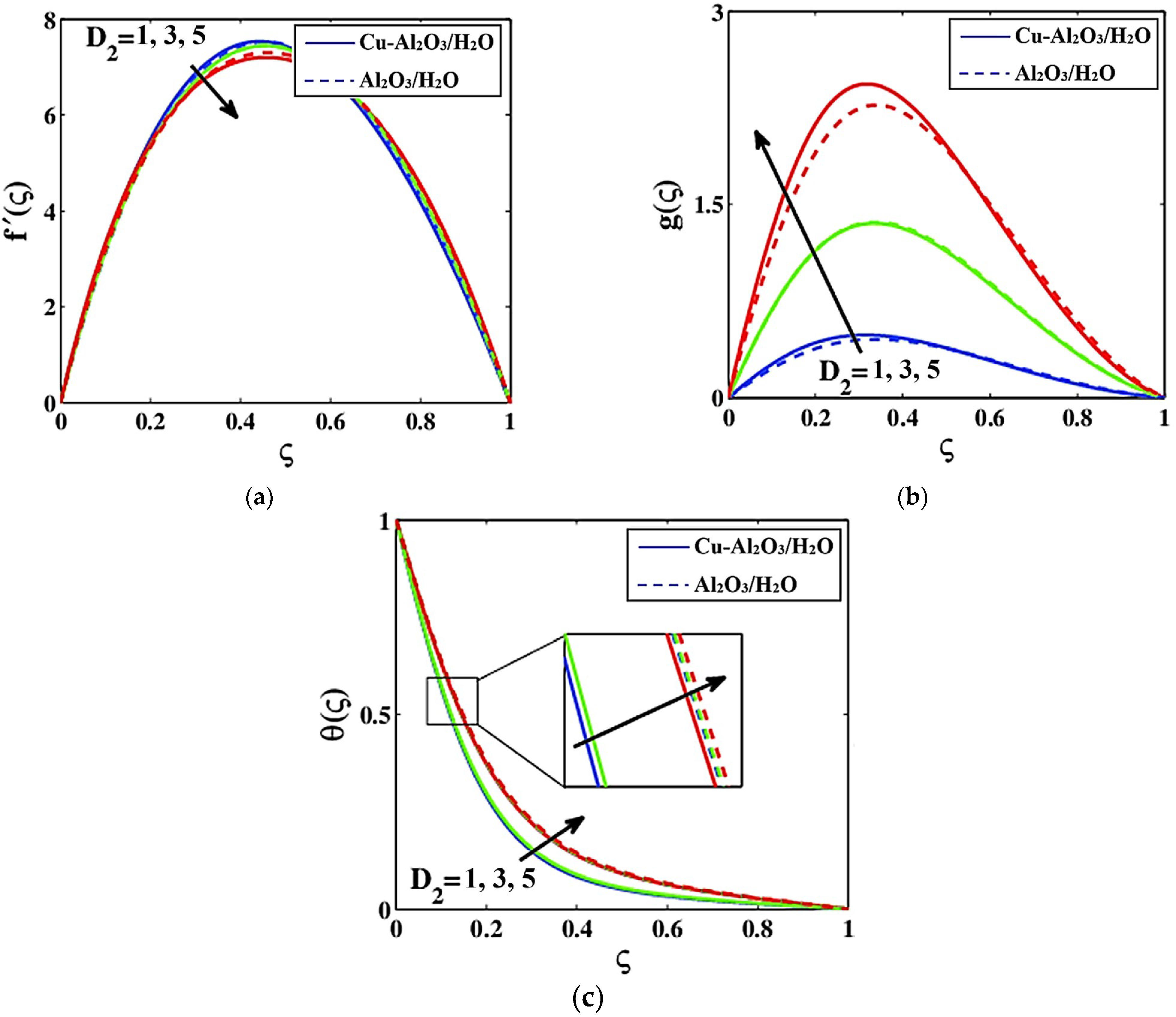
The effects of S , D 1 , D 2 , and D 3 on the Nusselt quantity are delineated in Figure 11a–d at the state of hybridized nanomolecules when ς = 0 . A magnification in S booms the thermal transport trend. The temperature of a liquid escalates in response to an amplification in the hybridized nanoparticles fractional size. This promotes sucking occurrence for an increase in the temperature that is soaked up by the liquid directly to an amplification in S which uplifts RHT. The inertial powers decrease the viscidness, and because of a growing shift in D 1 , it declines the liquid viscidness and additionally impedes liquid activity. RHT increases in the case of S and D 1 when the volume percentage of hybrid nanoparticles is increased. Heat transmission is inversely linked to fluidity. The fluid’s shearing thickener temperature rises, increasing the heat transfer phenomena. A magnified hybridized nanomolecules fractional size produces a liquid that is heavier, reducing the rotating phenomena D 2 and RHT. A non-negative shift in D 3 reduces the heat exchange phenomena. Lorentz power operates as a frictional force, slowing the rapidity of the liquid and magnifying Nusselt quantity.
A disparity in Nusselt quantity in the case of incremental change in S , D 1 , D 2 , and D 3 is displayed in Figure 12a–d at ς = 1 .The incremental change in the hybridized nanomolecules expands a liquid temperature at the wall but the liquid temperature lessens when moving away from the wall at ς = 1 . The sucking capability of a liquid is devalued, causing the thermal transport process to decline. A magnification in D 1 strengthens the inertial power in comparison to viscidity; it minimizes a liquid viscidness and boosts thermal transmit happening. It is clear that such a rotating manifestation of the liquid is a significantly more powerful intermediate zone than the distance from the plate ς = 1 ; it devalues the heat transmit occurrence. The heat transmission disasters are caused by an increase in D 3 at ς = 1 . The Lorentz power is less efficient at ς = 1 , it reduces the influence of the skin friction factor and enhances the heat exchange process. An enhancement of RHT phenomena enhances PTSC productivity and effectiveness.
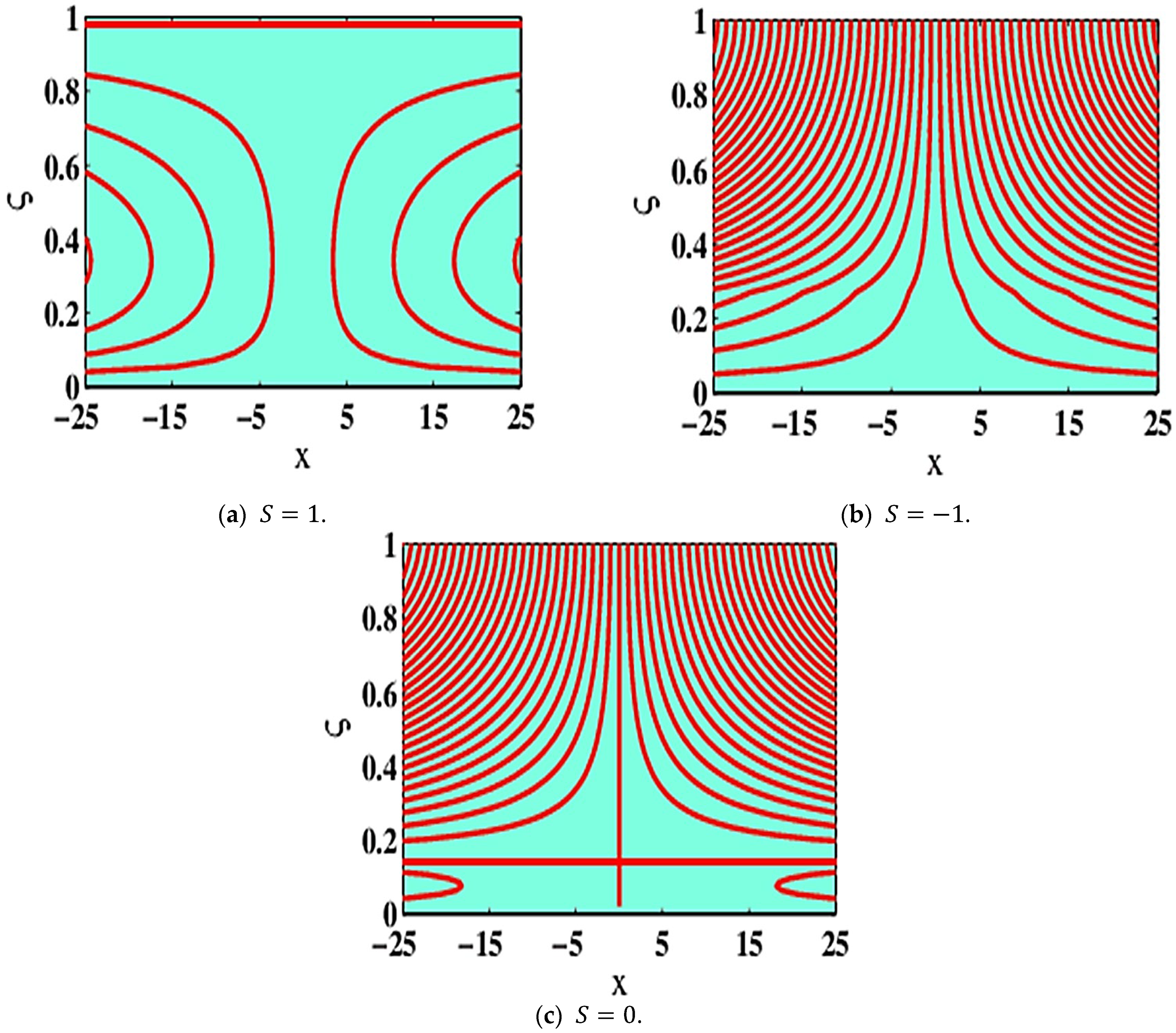
Stream lined variation in the case of the sucking (injection) variable S is exhibited in Figure 13a–c. Stream lines depict the behavior of liquid via a stretchable plate. When sucking is S = 1 , in comparison to the injection scenario S = 1 , the intervals among streaming lines are not effectively eliminated. Whilst the streaming lines are close enough, the liquid movement is comparatively high, as seen in the case of S = 1 against S = 1 and S = 0 .

6. Conclusions

The present investigation analyzes the impacts of utilizing Al2O3/H2O MNF and Cu-Al2O3/H2O electrically conducting HBNF on a spinning liquid via a stretchable plate in PTSC. The most important consequences of the existing scrutiny are outlined underneath:
  • In the presence of high Lorentz power, the friction force predominates, slowing the magnetization impact and flow rapidity outlines.
  • The inertial influences decrease the viscidness power in the state of a non-negative variant in D 1 and quickens the liquid flow and speed.
  • A positive variation in D 3 generates a force that is termed as Lorentz strength which behaves similar to a resisting effect, causing delays in the liquid flow.
  • The thermal flow rate at deeper lamina enhances when S and D 1 are non-negative for the state of enrichment in mixed nanomolecules volume fraction.
  • The heat transmission rate booms in a state of Cu-Al2O3/H2O HBNF rather than Al2O3 nanoparticles fluid.
  • Cu-Al2O3/H2O HBNF is considered the best thermic as well as an electrical conductor in contrast to Al2O3-water conventional nanofluid.
  • The incorporation of Cu-Al2O3 nanomolecules in water amplifies the execution and efficiency of PTSC.

Funding

This research received no external funding.

Institutional Review Board Statement

Not applicable.

Informed Consent Statement

Not applicable.

Data Availability Statement

Manuscript has no associated data.

Conflicts of Interest

The authors declare no conflict of interest.

Nomenclature

a Stretching rate ν f Kinematic viscosity ( kg   m 1   s 1 )
B 0 Magnetism force ( A   m 1 ) κ f , κ p 1 , κ p 2 Thermal conductivities ( Wm 2 K 1 )
C f Frictional force factor ( N ) σ f , σ p 1 , σ p 2 Electrical conductivities ( Sm 1 )
C p Specific heat ( Jkg 1 K 1 ) σ * Stephan Boltzmann constant (-)
f , g Dimensionless velocities Ω Angular quickness ( rad   s 1 )
k * Mass absorption coefficient ( m   kg 1 ) ς Factor of similar
N u Nusselt quantity θ Nondimensional temperature
p Pressure ( kg   m 1 s 2   or   Pa ) ϕ Fractional size
P r Prandtl quantity Θ ˘ Temperature ( K )
q w Wall heat fluxing ( Wm 2 ) Θ ˘ 0 Overhead plate temperature ( K )
x , y , z Cartesian coordinate system ( m ) Θ ˘ h Down-plate temperature ( K )
u , v , w Velocity components ( ms 1 ) Subscripts
U w Eextended plate speed ( ms 1 ) A Alumina
W 0 Suction/injection velocity ( ms 1 ) C Copper
Greek symbols f Normal liquid
ρ f , ρ p 1 , ρ p 2 Densities ( kg   m 3 ) p , p 1 , p 2 Solid nanomolecules
μ f Dynamic viscosity ( kg   m 1   s 1 ) h b n f , n f Hybridized and mono nanoliquid

References

  1. Choi, S.U.; Eastman, J.A. Enhancing Thermal Conductivity of Fluids with Nanoparticles; Argonne National Lab.: Lemont, IL, USA, 1995. [Google Scholar]
  2. Alklaibi, A.M.; Sundar, L.S.; Sousa, A.C.M. Experimental analysis of exergy efficiency and entropy generation of diamond/water nanofluids ow in a thermosyphon at plate solar collector. Int. Commun. Heat Mass Transf. 2021, 120, 105057. [Google Scholar] [CrossRef]
  3. Joseph, A.; Sreekumar, S.; Thomas, S. Energy and exergy analysis of SiO2/Ag-CuO plasmonic nanofluid on direct absorption parabolic solar collector, Renew. Energy 2020, 162, 1655–1664. [Google Scholar]
  4. Eltaweel, M.; Abdel-Rehim, A.A.; Attia, A.A. Energetic and exergetic analysis of a heat pipe evacuated tube solar collector using MWCNT/water nanofluid. Case Stud. Therm. Eng. 2020, 22, 100743. [Google Scholar] [CrossRef]
  5. Singh, G.; Singh, D.B.; Kumar, S.; Bharti, K.; Chhabra, S. A review of inclusion of nanofluids on the attainment of different types of solar collectors. Mater. Today: Proc. 2020, 38, 153–159. [Google Scholar] [CrossRef]
  6. Kaya, H.; Alkasem, M.; Arslan, K. Effect of nanoparticle shape of Al2O3/pure water nanofluid on evacuated U-Tube solar collector efficiency, Renew. Energy 2020, 162, 267–284. [Google Scholar]
  7. Olfian, H.; Ajarostaghi, S.S.M.; Ebrahimnataj, M. Development on evacuated tube solar collectors: A review of the last decade results of using nanofluids. Sol. Energy 2020, 211, 265–282. [Google Scholar] [CrossRef]
  8. Mahian, O.; Kianifar, A.; Kalogirou, S.A.; Pop, I.; Wongwises, S. A review of the applications of nanouids in solar energy. J. Heat Mass Transf. 2013, 57, 582–594. [Google Scholar] [CrossRef]
  9. Abu Bakar, S.; Arifin, N.; Khashi’Ie, N.; Bachok, N. Hybrid Nanofluid Flow over a Permeable Shrinking Sheet Embedded in a Porous Medium with Radiation and Slip Impacts. Mathematics 2021, 9, 878. [Google Scholar] [CrossRef]
  10. Waini, I.; Ishak, A.; Pop, I. Hybrid Nanofluid Flow over a Permeable Non-Isothermal Shrinking Surface. Mathematics 2021, 9, 538. [Google Scholar] [CrossRef]
  11. Devi, S.S.U.; Devi, S.P.A. Numerical investigation of three-dimensional hybrid Cu-Al2O3/water nanofluid flow over a stretching sheet with effecting Lorentz force subject to Newtonian heating. Can. J. Phys. 2016, 94, 490–496. [Google Scholar] [CrossRef]
  12. Fourier, B.J. Theorie Analytique de la Chaleur; Firmin Didot: Paris, France, 1822. [Google Scholar]
  13. Cattaneo, C. Sulla Conduzione Del Calore. Atti Sem. Mat. Fis. Univ. Modena 1984, 3, 83–101. [Google Scholar]
  14. Christov, C. On frame indifferent formulation of the Maxwell–Cattaneo model of finite-speed heat conduction. Mech. Res. Commun. 2008, 36, 481–486. [Google Scholar] [CrossRef]
  15. Hayat, T.; Javed, M.; Imtiaz, M.; Alsaedi, A. Effect of Cattaneo-Christov heat flux on Jeffrey fluid flow with variable thermal conductivity. Results Phys. 2017, 8, 341–351. [Google Scholar] [CrossRef]
  16. Hayat, T.; Aziz, A.; Muhammad, T.; Alsaedi, A. Three-dimensional ow of Prandtl fluid with Cattaneo-Christov double diffusion. Results Phys. 2018, 9, 290–296. [Google Scholar] [CrossRef]
  17. Hayat, T.; Muhammad, T.; Alsaedi, A. Impact of Cattaneo–Christov heat flux in three-dimensional flow of second grade fluid over a stretching surface. Chin. J. Phys. 2017, 55, 1242–1251. [Google Scholar] [CrossRef]
  18. Hayat, T.; Nadeem, S. Flow of 3D Eyring-Powell fluid by utilizing Cattaneo-Christov heat flux model and chemical processes over an exponentially stretching surface. Results Phys. 2018, 8, 397–403. [Google Scholar] [CrossRef]
  19. Ahmad, I.; Aziz, S.; Ali, N.; Khan, S.U.; Khan, M.I.; Tlili, I.; Khan, N.B. Thermally developed Cattaneo-Christov Maxwell nanofluid over bidirectional periodically accelerated surface with gyrotactic microorganisms and activation energy. Alex. Eng. J. 2020, 59, 4865–4878. [Google Scholar] [CrossRef]
  20. Hayat, T.; Farooq, M.; Alsaedi, A.; Al-Solamy, F. Impact of Cattaneo-Christov heat flux in the ow over a stretching sheet with variable thickness. AIP Adv. 2015, 5, 087159. [Google Scholar] [CrossRef]
  21. Mahanthesh, B.; Gireesha, B.J.; Raju, K. Cattaneo-Christov heat flux on UCM nanofluid ow across a melting surface with double stratification and exponential space dependent internal heat source. Inform. Med. Unlocked 2017, 9, 26–34. [Google Scholar] [CrossRef]
  22. Alebraheem, J.; Ramzan, M. Flow of nanofluid with Cattaneo–Christov heat flux model. Appl. Nanosci. 2019, 10, 2989–2999. [Google Scholar] [CrossRef]
  23. Mahmood, A.; Jamshed, W.; Aziz, A. Entropy and heat transfer analysis using Cattaneo-Christov heat flux model for a boundary layer ow of Casson nanofluid. Results Phys. 2018, 10, 640–649. [Google Scholar] [CrossRef]
  24. Shah, Z.; Dawar, A.; Khan, I.; Islam, S.; Ching, D.; Khan, A.Z. Cattaneo-Christov model for electrical magnetite micropolar Casson ferrofluid over a stretching/shrinking sheet using effective thermal conductivity model. Case Stud. Therm. Eng. 2019, 13, 100352. [Google Scholar] [CrossRef]
  25. Chaji, H.; Ajabshirchi, Y.; Esmaeilzadeh, E.; Heris, S.Z.; Hedayatizadeh, M.; Kahani, M. Experimental study on thermal efficiency of at plate solar collector using TiO2/water nanofluid. Modern Appl. Sci. 2013, 7, 60–69. [Google Scholar] [CrossRef]
  26. Ghasemi, S.E.; Ahangar, G. Numerical analysis of performance of solar parabolic trough collector with Cu-water nanofluid. Int. J. Nano Dimens. 2014, 5, 233–240. [Google Scholar]
  27. Sharma, K.; Kundan, L. Nanofluid based concentrating parabolic solar collector (NBCPSC): A new alternative. Int. J. Res. Mech. Eng. Technol. 2014, 4, 2249–5762. [Google Scholar]
  28. Buongiorno, J. Convective Transport in Nanofluids. J. Heat Transfer. 2006, 128, 240–250. [Google Scholar] [CrossRef]
  29. Afzal, K.; Aziz, A. Transport and heat transfer of time dependent MHD slip flow of nanofluids in solar collectors with variable thermal conductivity and thermal radiation. Results Phys. 2016, 6, 746–753. [Google Scholar] [CrossRef] [Green Version]
  30. Hussain, S.M.; Sharma, R.; Chamkha, A.J. Numerical and statistical explorations on the dynamics of water conveying Cu-Al2O3 hybrid nanofluid flow over an exponentially stretchable sheet with Navier’s partial slip and thermal jump conditions. Chin. J. Phys. 2021, 75, 120–138. [Google Scholar] [CrossRef]
  31. Shamshuddin, M.D.; Eid, M.R. Magnetized nanofluid flow of ferromagnetic nanoparticles from parallel stretchable rotating disk with variable viscosity and thermal conductivity. Chin. J. Phys. 2021, 74, 20–37. [Google Scholar] [CrossRef]
  32. Jouybari, H.J.; Saedodin, S.; Zamzamian, A.; Nimvari, M.E.; Wongwises, S. Effects of porous material and nanoparticles on the thermal performance of a flat plate solar collector: An experimental study. Renew. Energy 2017, 114, 1407–1418. [Google Scholar] [CrossRef]
  33. Parvin, S.; Ahmed, S.; Chowdhury, R. Effect of solar irradiation on forced convective heat transfer through a nanofluid based direct absorption solar collector. In AIP Conference Proceedings; AIP Publishing LLC.: Melville, NY, USA, 2017; Volume 1851, p. 20067. [Google Scholar] [CrossRef]
  34. Subramani, J.; Nagarajan, P.K.; Mahian, O.; Sathyamurthy, R. Efficiency and heat transfer improvements in a parabolic trough solar collector using TiO2 nanofluids under turbulent ow regime, Renew. Energy 2018, 119, 19–31. [Google Scholar]
  35. Smit, S.; Kessels, W.M.M. Variational method for the minimization of entropy generation in solar cells. J. Appl. Phys. 2015, 117, 134504. [Google Scholar] [CrossRef] [Green Version]
  36. Sciacovelli, A.; Verda, V.; Sciubba, E. Entropy generation analysis as a design tool—A review. Renew. Sustain. Energy Rev. 2015, 43, 1167–1181. [Google Scholar] [CrossRef]
  37. Bejan, A.; Kearney, D.W.; Kreith, F. Second Law Analysis and Synthesis of Solar Collector Systems. J. Sol. Energy Eng. 1981, 103, 23–28. [Google Scholar] [CrossRef]
  38. Liu, G.; Cengel, Y.A.; Turner, R.H. Exergy Analysis of a Solar Heating System. J. Sol. Energy Eng. 1995, 117, 249–251. [Google Scholar] [CrossRef]
  39. Ghanbarpour, M.; Khodabandeh, R. Entropy generation analysis of cylindrical heat pipe using nanofluid. Thermochim. Acta 2015, 610, 37–46. [Google Scholar] [CrossRef]
  40. Khan, M.I.; Hafeez, M.; Hayat, T.; Alsaedi, A. Magneto rotating flow of hybrid nanofluid with entropy generation. Comput. Methods Programs Biomed. 2019, 183, 105093. [Google Scholar] [CrossRef] [PubMed]
  41. Wang, W.-W.; Cai, Y.; Wang, L.; Liu, C.-W.; Zhao, F.-Y.; Sheremet, M.A.; Liu, D. A two-phase closed thermosyphon operated with nanofluids for solar energy collectors: Thermodynamic modeling and entropy generation analysis. Sol. Energy 2020, 211, 192–209. [Google Scholar] [CrossRef]
  42. Suzuki, A. A Fundamental Equation for Exergy Balance on Solar Collectors. J. Sol. Energy Eng. 1988, 110, 102–106. [Google Scholar] [CrossRef]
  43. Gbadeyan, J.A.; Titiloye, E.O.; Adeosun, A.T. Effect of variable thermal conductivity and viscosity on Casson nanofluid ow with convective heating and velocity slip. Heliyon 2020, 6, e03076. [Google Scholar] [CrossRef] [Green Version]
  44. Mahdy, A.; Chamkha, J.; Nabwey, H. Entropy analysis and unsteady MHD mixed convection stagnation-point ow of Casson nanofluid around a rotating sphere. Alex. Eng. J. 2020, 59, 1693–1703. [Google Scholar] [CrossRef]
  45. Kamran, A.; Hussain, S.; Sagheer, M.; Akmal, N. A numerical study of magnetohydrodynamics flow in Casson nanofluid combined with Joule heating and slip boundary conditions. Results Phys. 2017, 7, 3037–3048. [Google Scholar] [CrossRef]
  46. Goud, B.S.; Kumar, P.; Malga, S. Effect of heat source on an unsteady MHD free convection ow of Casson fluid past a vertical oscillating plate in porous medium using finite element analysis, Partial Differ. Equ. Appl. Math. 2020, 2, 100015. [Google Scholar]
  47. Farahat, S.; Sarhaddi, F.; Ajam, H. Exergetic optimization of flat plate solar collectors. Renew. Energy 2009, 34, 1169–1174. [Google Scholar] [CrossRef]
  48. Yejjer, O.; Kolsi, L.; Aich, W.; Al-Rashed, A.A.; Borjini, M.N.; Ben Aissia, H. Study of three-dimensional natural convection and entropy generation in an inclined solar collector equipped with partitions. Heat Transfer Asian Res. 2017, 46, 1312–1326. [Google Scholar] [CrossRef]
  49. Verma, S.K.; Tiwari, A.K.; Chauhan, D.S. Experimental evaluation of flat plate solar collector using nanofluids. Energy Convers. Manag. 2017, 134, 103–115. [Google Scholar] [CrossRef]
  50. Moghadam, M.C.; Edalatpour, M.; Solano, J.P. Numerical Study on Conjugated Laminar Mixed Convection of Alumina/Water Nanofluid Flow, Heat Transfer, and Entropy Generation Within a Tube-on-Sheet Flat Plate Solar Collector. J. Sol. Energy Eng. 2017, 139, 041011. [Google Scholar] [CrossRef]
  51. Nasrin, R.; Parvin, S.; Alim, M.A. Heat Transfer and Collector Efficiency through a Direct Absorption Solar Collector with Radiative Heat Flux Effect. Numer. Heat Transfer Part A Appl. 2015, 68, 887–907. [Google Scholar] [CrossRef]
  52. Shahzad, F.; Jamshed, W.; Sajid, T.; Nisar, K.S.; Eid, M.R. Heat Transfer Simulation for 3D MHD Rotating Hybrid NanoFluid Flow Between Parallel Plates in Parabolic Trough Solar Collector: A Numerical Study. J. Eng. Thermophys. 2021, 30, 704–726. [Google Scholar] [CrossRef]
  53. Khan, A.; Saeed, A.; Gul, T.; Mukhtar, S.; Ali, I.; Jawad, M. Radiative swirl motion of hydromagnetic Casson nanofluid ow over rotary cylinder using Joule dissipation impact. Phys. Scr. 2021, 96, 045206. [Google Scholar] [CrossRef]
  54. Ghadikolaei, S.; Yassari, M.; Sadeghi, H.; Hosseinzadeh, K.; Ganji, D. Investigation on thermophysical properties of Tio2–Cu/H2O hybrid nanofluid transport dependent on shape factor in MHD stagnation point flow. Powder Technol. 2017, 322, 428–438. [Google Scholar] [CrossRef]
  55. Maskeen, M.; Zeeshan, A.; Mehmood, O.; Hassan, M. Heat transfer enhancement in hydromagnetic alumina-copper/water hybrid nanofluid ow over a stretching cylinder. J. Therm. Anal. Calorim. 2019, 138, 1127–1136. [Google Scholar] [CrossRef]
  56. Hussain, S.; Haq, R.-U.; Khan, Z.; Nadeem, S. Water driven flow of carbon nanotubes in a rotating channel. J. Mol. Liq. 2015, 214, 136–144. [Google Scholar] [CrossRef]
  57. Srinivasulu, T.; Goud, S. Effect of inclined magnetic field on ow, heat and mass transfer of Williamson nanofluid over a stretching sheet. Case Stud. Therm. Eng. 2021, 23, 100819. [Google Scholar] [CrossRef]
  58. Cebeci, T.; Bradshaw, P. Physical and Computational Aspects of Convective Heat Transfer; Springer: New York, NY, USA, 1988. [Google Scholar]
  59. Keller, H.B. Numerical Methods for Two-Point Boundary Value Problems; Dover Publications: New York, NY, USA, 1992. [Google Scholar]
Figure 1. PTSC model.
Mathematics 10 02605 g001
Figure 2. The geometry of the problem.
Mathematics 10 02605 g002
Figure 3. Flowing diagram of Keller-box procedure.
Mathematics 10 02605 g003
Figure 4. Structural grid for diverse estimates.
Mathematics 10 02605 g004
Figure 5. (a) f ς , (b) g ς , and (c) θ ς with ϕ and ϕ h b n f when D 1 = D 2 = D 3 = 2 , S = 1 .
Mathematics 10 02605 g005
Figure 6. (a) f ς , (b) g ς , and (c) θ ς with S when D 1 = D 2 = D 3 = 0.5 , ϕ = ϕ h b n f = 0.05 .
Mathematics 10 02605 g006
Figure 7. (a) f ς , (b) g ς , and (c) θ ς with D   1 when D 2 = 0.2 , D 3 = 0 , ϕ = ϕ h b n f = 0.05 , S = 1 .
Mathematics 10 02605 g007
Figure 8. (a) f ς , (b) g ς , and (c) θ ς with D 2 when D 1 = 0.5 , D 3 = 1 , ϕ = ϕ h b n f = 0.05 , S = 3 .
Mathematics 10 02605 g008
Figure 9. (a) f ς , (b) g ς , and (c) θ ς with D 3 when D 1 = 1 , D 2 = 2 , ϕ = ϕ h b n f = 0.05 , S = 1 .
Mathematics 10 02605 g009
Figure 10. Temperature distribution against (a) N r , (b) g ς , and (c) θ ς w.r.t. P r when D 1 = 1 , D 2 = 2 , ϕ = ϕ h b n f = 0.05 , S = 1 .
Mathematics 10 02605 g010
Figure 11. Nusselt amount changes at ς = 0 for (a) S , (b) D 1 , (c) D 2 , and (d) D 3 amounts.
Mathematics 10 02605 g011
Figure 12. Nusselt amount at ς = 1 for diverse (a) S, (b) D 1 , (c) D 2 , and (d) D 3 .
Mathematics 10 02605 g012
Figure 13. Variation of streaming lines for various values of S .
Mathematics 10 02605 g013
Table 1. The physical thermal attributes of NF [54].
CharacteristicNF
Dynamical viscidness μ n f = μ f ( 1 ϕ ) 2.5
Consistency ρ n f = 1 ϕ ρ f + ϕ ρ p
Heat capacity ( ρ C p ) n f = 1 ϕ ( ρ C p ) f + ϕ ( ρ C p ) p
Thermal conductance κ n f κ f = κ p + 2 κ f 2 ϕ κ f κ p κ p + 2 κ f + ϕ κ f κ p
Electric conductance σ n f σ f = 1 + 3 σ p σ f ϕ σ p + 2 σ f σ p σ f ϕ
Table 2. The physical thermal attributes of hybrid nanofluid [54].
CharacteristicHBNF
Dynamical viscidness ϕ 1 = μ h n f μ f = ( 1 ϕ A ) 2.5 1 ( 1 ϕ C ) 2.5 1
Density ϕ 2 = ρ h n f ρ f = 1 ϕ C 1 ϕ A + ϕ a ρ p 1 ρ f + ϕ b ρ p 2 ρ f
Heat capacitance ϕ 3 = ( ρ C p ) h n f ( ρ C p ) f = 1 ϕ C 1 ϕ A + ϕ A ( ρ C p ) p 1 ( ρ C p ) f + ϕ C ( ρ C p ) p 2 ( ρ C p ) f
Thermal conductivity ϕ 4 = κ h n f κ f = κ p 2 + 2 κ n f 2 ϕ C κ n f κ p 2 κ p 2 + 2 κ n f + ϕ C κ n f κ p 2 × κ p 1 + 2 κ f + ϕ A κ f κ p 1 κ p 1 + 2 κ f 2 ϕ A κ f κ p 1
Electrical conductivity ϕ 5 = σ h n f σ f = 1 + 3 ϕ A σ p 1 + ϕ C σ p 2 σ f ϕ A + ϕ C ϕ A σ p 1 + ϕ C σ p 2 ϕ A + ϕ C σ f + 2 ϕ A σ p 1 + ϕ C σ p 2 σ f ϕ A + ϕ C
Table 3. The thermophysical aspects of conventional water and nanomolecules [55].
Physical PropertiesH2OAl2O3Cu
ρ   kg / m 3 99739708933
C p   J / kgK 4179765.0385.0
κ   W / mK 0.61340401
σ   ( Ω   m ) 1 0.0510−125.96 × 10⁷
Table 4. Computational amounts of θ 0 when ϕ = ϕ A = ϕ C = 0 .
S Current AnalysisRef. [56]Current AnalysisRef. [56]
at ς = 0 at ς = 0 at ς = 1 at ς = 1
−10.4966250.496625 1.4262311.426231
01.0000001.000000 1.000000 1.000000
11.7203661.720366 0.631314 0.631314
Table 5. Frictional force factors changes.
ϕ A Al2O3/H2O (NF)Cu-Al2O3/H2O (HBNF)
R e x C f     at   ς = 0                 R e x C f     at   ς = 1                 R e x C f     at ς = 0                 R e x C f     at ς = 1
0.0052.886026.876842.277875.51274
0.032.831886.386792.310695.55099
0.052.779296.876842.324105.55447
0.082.686677.476952.324015.56782
0.12.616867.789672.311315.58281
Table 6. Diversity in the Nusselt quantities.
ϕ A Al2O3/H2OCu-Al2O3/H2ORelative %
N u x R e x     at   ς = 0 N u x R e x     at   ς = 0   N u C u N u A l 2 O 3 N u C u × 100
0.0053.035103.248866.803%
0.032.925313.128886.725%
0.052.841543.037446.664%
0.12.646072.824376.519%
Publisher’s Note: MDPI stays neutral with regard to jurisdictional claims in published maps and institutional affiliations.

