Article

Dynamics of Triple Diffusive Free Convective MHD Fluid Flow: Lie Group Transformation

by
Vellaboyina Nagendramma
1,†,
Putta Durgaprasad
2,
Narsu Sivakumar
3,
Battina Madhusudhana Rao
4,
Chakravarthula Siva Krishnam Raju
5,
Nehad Ali Shah
6,† and
Se-Jin Yook
5,*
1
Department of Mathematics, Presidency University, Bangalore 560064, Karnataka, India
2
Division of Mathematics, Vellore Institute of Technology, Chennai Campus, Chennai 600127, Tamil Nadu, India
3
Department of Mathematics, SRM Institute of Science and Technology, Kattankulathur 603203, Tamil Nadu, India
4
Faculty Mathematics, Department of Information Technology, University of Technology and Applied Sciences, Muscat 133, Oman
5
School of Mechanical Engineering, Hanyang University, 222 Wangsimni-ro, Seongdong-gu, Seoul 04763, Korea
6
Department of Mechanical Engineering, Sejong University, Seoul 05006, Korea
*
Author to whom correspondence should be addressed.
These authors contributed equally to this work and are co-first authors.
Mathematics 2022, 10(14), 2456; https://doi.org/10.3390/math10142456
Submission received: 13 May 2022 / Revised: 27 June 2022 / Accepted: 12 July 2022 / Published: 14 July 2022
(This article belongs to the Special Issue Mathematical Problems in Mechanical Engineering)

Abstract

:
This analysis is interested in the dynamic flow of incompressible triple diffusive fluid flowing through a linear stretched surface. The current study simulates when Boussinesq approximation and MHD are significant. As for originality, a comparative study of all the results for opposing and assisting flow cases is provided. Lie-group transformation is utilized to determine symmetry depletions of partial differential equations. The transformed system of ordinary differential equations is solved using the Runge-Kutta shooting technique. The impacts of magnetic parameter, buoyancy ratio parameter of temperature and concentration, and Lewis number on velocity, temperature, and concentration are depicted through graphs. We observed that the magnetic field parameter decelerates in velocity distribution for both fluid flow cases. Additionally, the same phenomenon was noticed with the buoyancy ratio parameters on both salt concentration distributions. Finally, the influence of heat and mass transfer rates decreases for both fluid flow cases with an increase in Lewis number.

1. Introduction

The flow of mass and heat transfer has many applications in science, industry, technical processes, and many theoretical or experimental disciplines. As examples, take aerospace, power generation, automotive, materials, and chemical processing industries [1,2,3]. Magneto-hydro dynamics (MHD) is one of the branches of physics used to analyze the fluids dynamics with the help of magnetic effects. Its applications have been extensive in numerous disciplines ranging from the study of solar winds [4] to MHD-driven biomedical sensors [5] and actuators [6,7]. Massoudi et al. [8] examined the impacts of a nanofluid’s thermal radiation and magnetic field inside a nonagon inclined cavity embedded in a porous medium. Massoudi et al. [9] used a MHD W-shaped inclined cavity saturated with Ag/Al2O3 hybrid nanofluid for uniform heat generation/absorption. Lie theory is a field of group theory that deals with continuous symmetry. It has a component which is close to identity transformation. Sophie Lie devised symmetry analysis, also known as Lie group analysis, to identify point transformations that allow a differential equation to be transferred to itself. Almost every known accurate integration technique for ordinary and differential equations is gathered in this transformation [9]. The Lie group transformation is a method of determining all aspects of a differential equation that does not require any extempore hypotheses or foreknowledge of the equation.
For most nonlinear differential equations, the approximate solutions are numerical due to the complexity of the problems [10]. He et al. [11] discussed on new analytical methods for cleaning up the solution of nonlinear equations. Massoudi et al. [12] studied numerical techniques on magneto natural convection of SWCNT nanofluid inside a T-inverted cavity. There are many general methods for solving linear and nonlinear partial differential equations. The Lie group theory, explained in [13], is the usual approach. Symmetry groups are invariant transformations that do not change the structure of the equations. Using this transformation, one can find the exact solution of differential equations developed by Sophie Lie about one century ago. Nowadays, the method is used widely. It creates a new solution from an existing one, rather than looking for so-called similar solutions [14]. This transformation has an n-independent variable partial differential system that can be converted to a system of n 1 independent variables, and if n = 2 , then the situation is considered best. It is one of the most effective tools for developing similarity transformations. Scaling transformation is the most common tool used to apply to the boundary layer equation in fluid dynamics. By reducing the number of independent variables, this transformation converts a system of nonlinear coupled partial differential equations regulating fluid motion into a system of coupled ordinary differential equations. Using nanofluid, Uddin et al. [15] utilized this transformation to analyze the boundary layer in MHD fluid flow on a stretched surface. MHD heat transfer in thermal slip using a semi-infinite domain and Carreau fluid was discussed by Rehman et al. [16]. Using this transformation, many researchers gave exact solutions to their problems [17,18].
The fluid motion created by the buoyancy forces is called free convection. Heat transfer in free convection depends on fluid circulation over and around the object, which is induced by temperature gradients, which create density gradients. In heat transfer, many applications were developed, such as food heating processing and cooling systems in which free convection is assertive. The sterilization process of food in cans and meat freezing are controlled by free convection. In the presence of a chemical reaction, researchers [19] analyzed an unsteady free convection MHD flow around a vertical cone in porous media with variable heat and mass flux. A lot of research is carried out in the area of free convection MHD flow [20,21,22,23,24,25].
In general, free convection is merely due to heat transfer and not in the mode of forced flow. In gas or liquid, the density differences are induced by temperature differences. Due to its numerous applications, the convective process has grown important over the last century. Bernard started the convective process experiments after that carried out by Rayleigh [26]. Triple diffusive free convection [27] develops when a fluid is applied to three density gradients with different diffusion rates. In this study, the triple diffusion is formulated by the diffusion of heat and species concentrations, a linear stability analysis for triple diffusive convection in Oldroyd-B fluid is carried out, and the expression of Rayleigh number for stationary and oscillatory convection is achieved [28]. Patil [29] examined a quadratic mixed convective nanofluid flow over a wedge by considering viscous dissipation. He observed that the rate of heat transfer increases with an increase in Biot number. In the normal mode theory, introducing a Maxwell fluid to a saturated porous layer causes triple diffusive convection [30]. In a time-dependent model, Khan et al. [31] investigated a triple diffusive natural convective flow along with a vertical plate. The heat transfer rate increased as the volume fraction distribution of nanoparticles increased. Triple diffusive convective importance was analyzed [32,33,34,35,36,37,38].
Few works have been performed using Lie group transformation analysis, as per the authors’ knowledge of the literature in most practical uses; however, the components of mass and heat are inextricably linked. The heat and mass diffusion components, on the other hand, are invariably coupled in most real-world applications. This fact prompted us to investigate the combined impacts of mass diffusion and heat on magnetohydrodynamic free-convective flow in the boundary layer. As far as we can tell, the findings of this work appear to be perfectly consistent with previous research, and due to their simplicity, easily transferable to relevant applications.

2. Mathematical Model and Formulation

The rate of mass change and heat transfer performance of an electrically conducting viscous fluid in a steady, triple-diffusive, two-dimensional hydro-magnetic flow follow. A uniformly strong magnetic field B is introduced perpendicular to the flow direction. Except for the influences of density variation on concentration and temperature, all liquid properties are assumed to be uniform. The surface temperature should be maintained at T w , higher than the constant. With the help of Lie group transformation analysis, we studied a triple-diffusive, free-convective, 2D, steady laminar flow through a stretching surface and its incompressible fluid flow model.
Under the pre-defined assumptions mentioned above, the governing equations are expressed as shown below [18].
u ¯ x ¯ + v ¯ y ¯ = 0 ,
u ¯ u ¯ x ¯ + v ¯ u ¯ y ¯ = ϑ 2 u ¯ y ¯ 2 + g β T T T + g β c 1 C C 1 + g β c 2 C C 2 σ B 2 ρ u ¯ ,
u ¯ T x ¯ + v ¯ T y ¯ = α 2 T y ¯ 2 ,
u ¯ C 1 x ¯ + v ¯ C 1 y ¯ = D S 1 2 C 1 y ¯ 2 ,
u ¯ C 2 x ¯ + v ¯ C 2 y ¯ = D S 2 2 C 2 y ¯ 2 .
Along the boundary conditions
u ¯ = u w ,     v ¯ = 0 ,     T = T w ,     C 1 = C 1 w ,   C 2 = C 2 w       at       η = 0 , u ¯ u ,     T T ,     C 1 C 1 ,     C 2 C 2     as       η .
To non-dimensionalize the above-mentioned Equations from (1) to (5) together with Equation (6), the following similarity transformations are considered.
u = u ¯ a ϑ , u = v ¯ a ϑ , x = x ¯ ϑ a , y = y ¯ ϑ a θ = T T T w T ,   ϕ 1 = C 1 C 1 C 1 w C 1 ,   ϕ 2 = C 2 C 2 C 2 w C 2 .
We substitute above non-dimensional quantities into Equations (1)–(5), along with the boundary conditions (6), and then complete simplification results in the following non-dimensional differential equations:
u x + v y = 0 ,
u u x + v u y = 2 u y 2 σ B 2 ρ a u + λ θ + N C 1 ϕ 1 + N C 2 ϕ 2 ,
u θ x + v θ y = 1 Pr 2 θ y 2 ,
u ϕ 1 x + v ϕ 1 y = D S 1 ν 2 ϕ 1 y 2 ,
u ϕ 2 x + v ϕ 2 y = D S 2 ν 2 ϕ 2 y 2 .
With the boundary conditions
u = x ,     v = 0 ,     θ = 1 ,     ϕ 1 = 1 ,     ϕ 2 = 1     at     η = 0 , u 0 ,     θ 0 ,     ϕ 1 0 ,     ϕ 2 0     as     η ,
where λ = g β T Δ T a a ϑ , N C 1 = g β C 1 Δ C 1 a a ϑ , N C 2 = g β C 2 Δ C 2 a a ϑ are the thermal, salt_1, and salt_2 solutal buoyancy ratios.

3. Scaling Transformations

The stream function ψ is introduced before scaling modifications are applied, as demonstrated below [17]:
u = ψ y   and   v = ψ x
Replace the above Equation (14) in to (8)–(12) together with the boundary conditions (13). Obviously, Equation (8) is satisfied by them. Additionally, remaining equations are transformed as below:
ψ x 2 ψ x y ψ x 2 ψ y 2 = 3 ψ y 3 σ B 2 ρ a ψ y λ θ + N C 1 ϕ 1 + N C 2 ϕ 2 ,
ψ y θ x ψ x θ y = α ν 2 θ y 2 ,
ψ y ϕ 1 x ψ x ϕ 1 y = D S 1 ν 2 ϕ 1 y 2 ,
ψ y ϕ 2 x ψ x ϕ 2 y = D S 2 ν 2 ϕ 2 y 2 .
With the boundary conditions
ψ y = x ,       ψ x = 0 ,     θ = 1 ,       ϕ 1 = 1 ,       ϕ 2 = 1     at     η = 0 , ψ y 0 ,       θ 0 ,     ϕ 1 0 ,       ϕ 2 0       as       η .
Additionally,
e ε r 2 r 3 ψ * y * = 1 ,       e ε r 1 r 3 = 0 ,     e ε r 4 θ * = 0 .
We suppose that ε , as a smaller scale transformation parameter. Then, the transformation F (a specified set of Lie-group transformation analysis) is reflected as shown below:
F :   x * = x e ε r 1 ,     y * = y e ε r 2 ,     ψ * = ψ e ε r 3 , θ * = θ e ε r 4 ,     ϕ 1 * = ϕ 1 e ε r 5 ,     ϕ 2 * = ϕ 2 e ε r 6 ,
where r 1 , r 2 , r 3 , r 4 , r 5 , r 6 are real numbers. The point of the transformation defined through (21) is to convert the coordinates as x , y , ψ , θ , ϕ 1 , ϕ 2 to x * , y * , ψ * , θ * , ϕ 1 * , ϕ 2 * . With the help of Lie group analysis mentioned in (15), Equations (15)–(18) are transformed as:
e ε r 1 + 2 r 2 2 r 3 ψ * x * 2 ψ * x * y * ψ * x * 2 ψ * y * 2 = e ε 3 r 2 r 3 3 ψ * y * 3 σ B 2 ρ a e ε r 2 r 3                                                                                                                         λ e ε r 4 θ + N C 1 e ε r 5 ϕ 1 + N C 2 e ε r 6 ϕ 2 ,
e ε r 1 + r 2 r 3 r 5 ψ * y * θ * x * ψ * x * θ * y * = a ν e ε 2 r 2 r 4 2 θ * y * 2 ,
e ε r 1 + r 2 r 3 r 5 ψ * y * ϕ 1 * x * ψ * x * ϕ 1 * y * = D S 1 ν e ε 2 r 2 r 5 2 ϕ 1 * y * 2 ,
e ε r 1 + r 2 r 3 r 6 ψ * y * ϕ 2 * x * ψ * x * ϕ 2 * y * = D S 2 ν e ε 2 r 2 r 6 2 ϕ 2 * y * 2 .
Equations (22)–(25) will remain invariant after the translation, if the exponent of this converted system of equations which satisfies the resulting linear equations is as follows:
r 1 = 2 r 2 2 r 3 = 3 r 2 r 3 = r 2 r 3 = r 4 = r 5 = r 6 ,
r 1 + r 2 r 3 r 4 = 2 r 2 r 4 ,
r 1 + r 2 r 3 r 5 = 2 r 2 r 5 ,
r 1 + r 2 r 3 r 6 = 2 r 2 r 6 .
By solving above linear Equations (26)–(29) simultaneously, we find:
r 1 = r 1 ,     r 2 = 0 ,     r 3 = r 1 ,   r 4 = 0 ,     r 5 = 0 ,     r 6 = 0 .
Substituting the above values (30) into the scaling transformations given in (21), we get:
F :   x * = x e ε r 1 ,     y * = y ,     ψ * = ψ e ε r 1 ,     θ * = θ ,     ϕ 1 * = ϕ 1 ,     ϕ 2 * = ϕ 2 .
The Taylor series expansions are:
x * x = x ε r 1 ,     y * y = 0 ,     ψ * ψ = ψ ε r 1 ,     θ * θ = 0 ,     ϕ 1 * ϕ 1 = 0 ,     ϕ 2 * ϕ 2 = 0 .
A simple algebraic expression for the above transformations (31) with the help of Taylor series expansion leads to a mono parametric group of transformations in the form of the characteristic equation given below:
d x x r 1 = d y 0 = d ψ ψ r 1 = d θ 0 = d ϕ 1 0 = d ϕ 2 0 .
From Equation (32), we can easily obtain new similarity transformations as:
y = η ,     ψ = x   f η ,   θ = θ η ,     ϕ 1 = ϕ 1 η ,     ϕ 2 = ϕ 2 η ,
where η is the similarity variable and f ,     θ ,     ϕ 1 ,     ϕ 2 are the dependent variables. Now, we substitute the above quantities specified in Equation (33) into PDEs (16)–(18) in boundary conditions mentioned in (19). We obtain the set of ordinary differential equations as:
f + f f ( f ) 2 M f + λ θ + N C 1 ϕ 1 + N C 2 ϕ 2 = 0 ,
θ + Pr f θ = 0 ,
ϕ 1 + L e 1 f ϕ 1 = 0 ,
ϕ 2 + L e 2 f ϕ 2 = 0 .
Together with the boundary conditions:
f = 1 ,     f = 0 ,     θ = 1 ,     ϕ 1 = 1 ,     ϕ 2 = 1     at     η = 0 , f 0 ,     θ 0 ,     ϕ 1 0 ,     ϕ 2 0     as     η ,
with the predefined parameters
M = σ B 2 ρ a ,     λ = g β T Δ T a a ϑ ,     N C 1 = g β C 1 Δ C 1 a a ϑ ,     N C 2 = g β C 2 Δ C 2 a a ϑ ,     Pr = ν α ,     L e 1 = ν D S 1 ,     L e 2 = ν D S 2 .
Furthermore, λ > 0 and λ < 0 represents buoyancy assisting flow and buoyancy opposing flow, respectively.

4. Numerical Results and Discussion

The effects of triple diffusive free convective magnetohydrodynamic fluid flow in a linearly stretching sheet were studied numerically. Lie group transformation analysis converts a collection of nonlinear partial differential equations and boundary situations into a set of ODEs. BVP4C resolved the system of the reduced nonlinear ODEs with corresponding boundary conditions in MATLAB. Table 1 shows a great correlation between the present results and the results of Ferdows et al. [17].
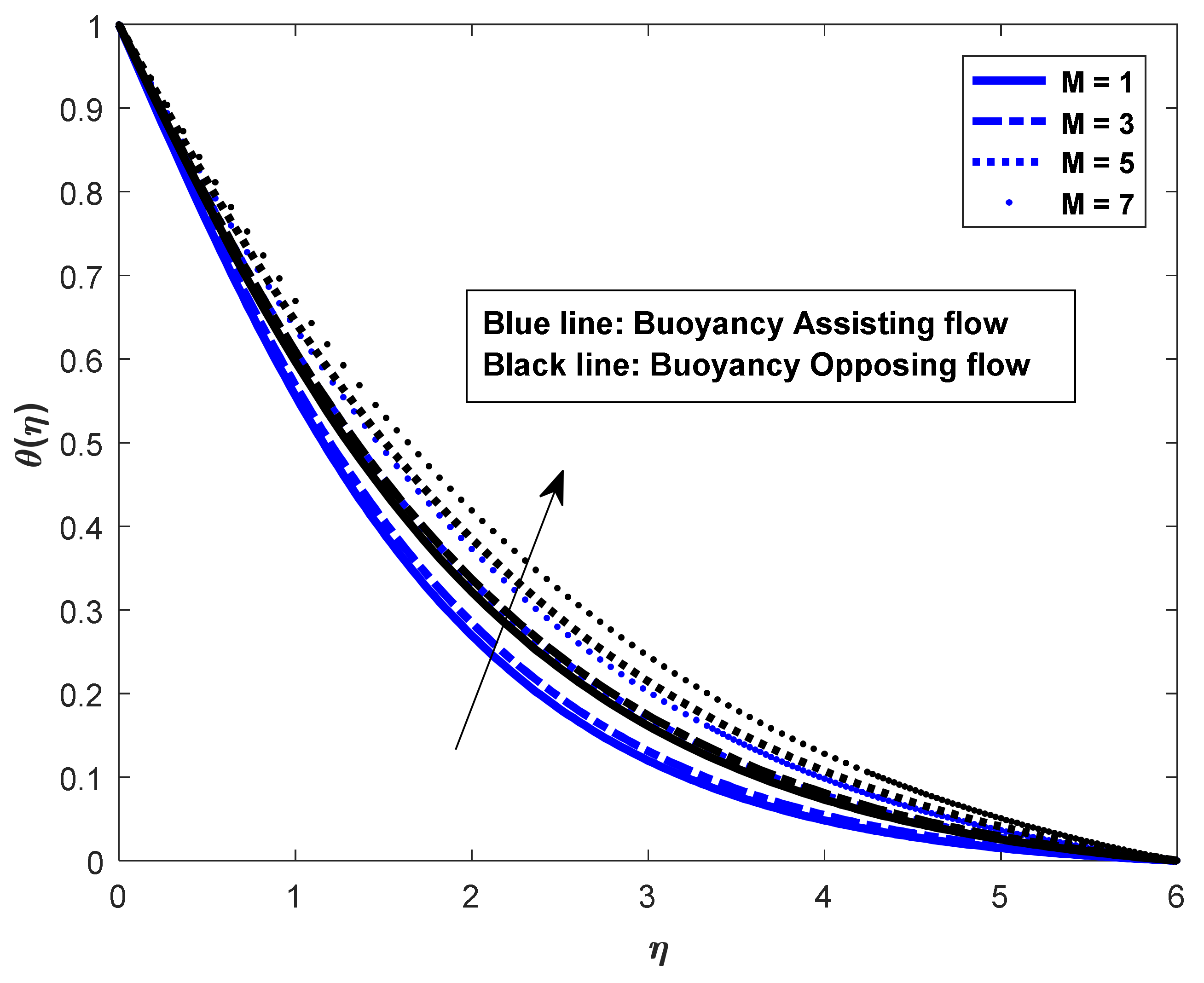
The influences of M on the velocity f η , temperature θ η , salt_1, and salt_2 concentration fields ϕ 1 η , ϕ 2 η on assisting flow ( λ > 0 ) and opposing flow ( λ < 0 ) are shown in Figure 1, Figure 2, Figure 3 and Figure 4. As illustrated in Figure 1, f η the surface decreases in assisting and opposing flows. It can be seen that increasing the value of the magnetic field parameter decreases the momentum boundary layer thickness. This is because the strong magnetic field inside the boundary layer increases the Lorentz force, which strongly resists flow in the opposite direction. It is also worth noting that the presence of a magnetic field reduces velocity near the wall while increasing velocity far away. The effects of magnetic parameters on temperature and concentration distributions are shown in Figure 2, Figure 3 and Figure 4. As the value rises, the fluid becomes warmer, raising the temperature. The thickness of the thermal boundary layer is always increased by the presence of a magnetic field, and the concentration field is likewise increased by the magnetic parameter.
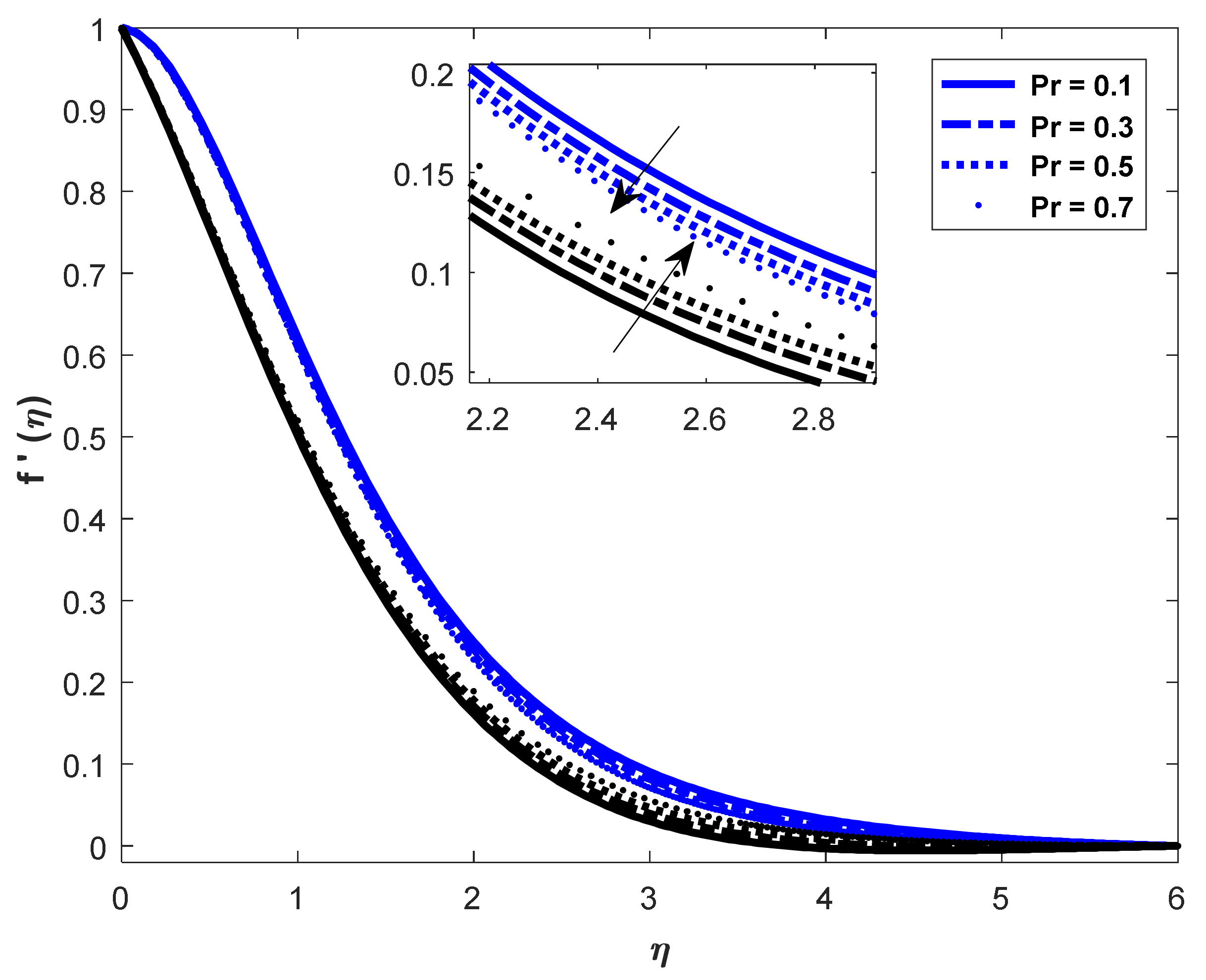
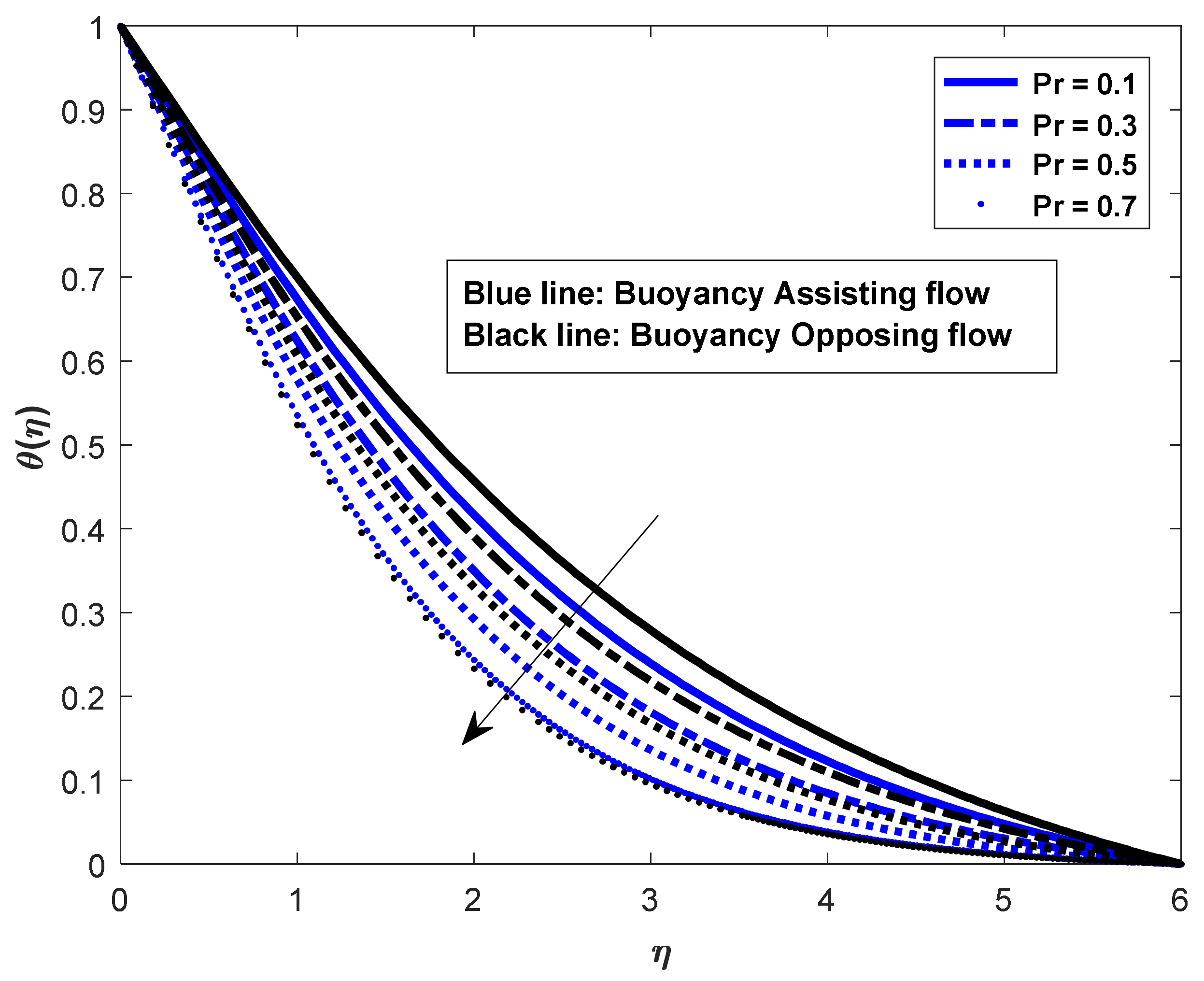
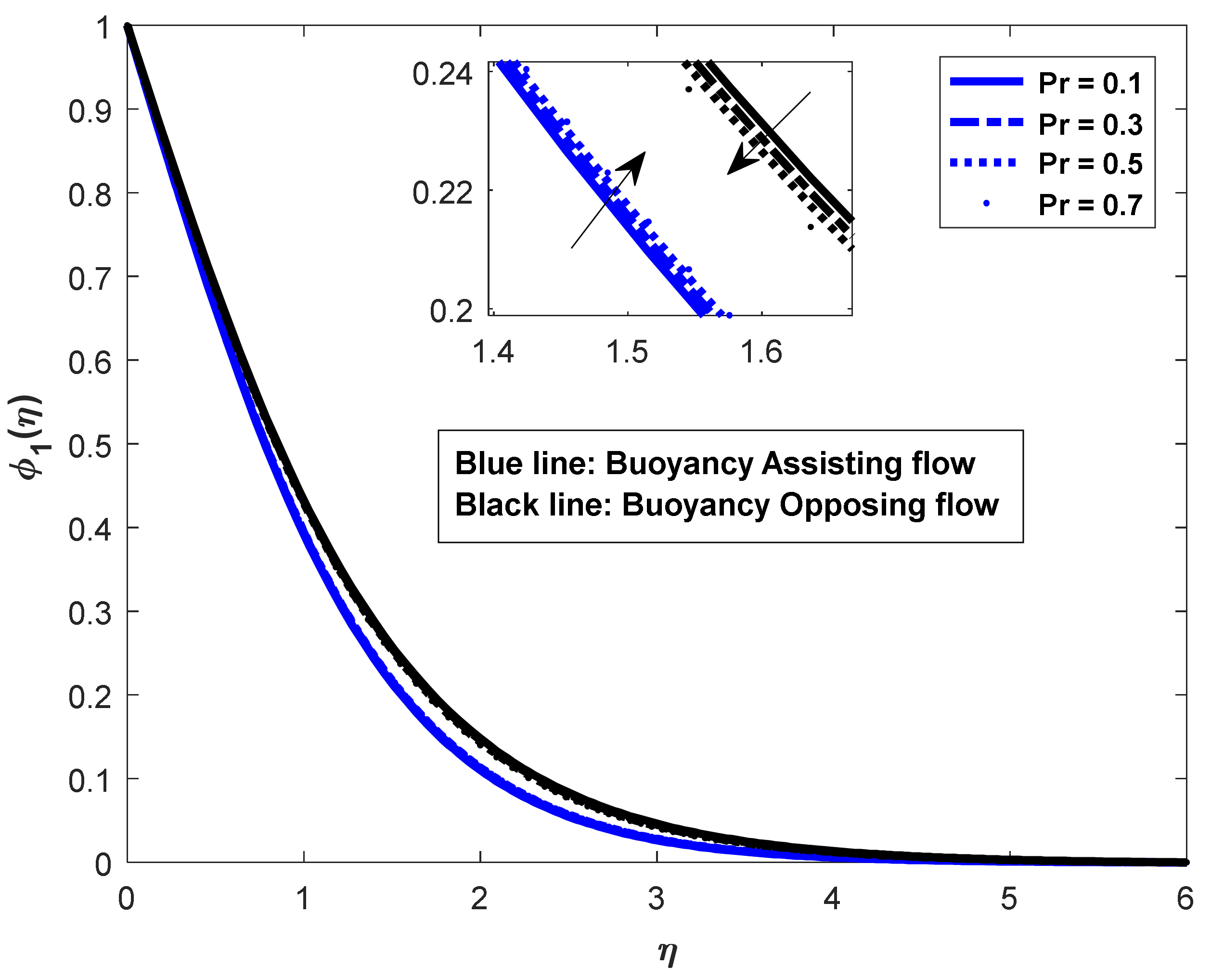
The influences of the Prandtl number are seen in Figure 5, Figure 6, Figure 7 and Figure 8. The dimensional velocity profile grows as the Prandtl number increases in the opposing flow case and reduces in the helping flow case, as seen in Figure 5. In contrast, in the natural convective flow of a regular fluid over a vertical surface, the thickness of the hydrodynamic boundary layer reduces as the Prandtl number grows, and the vertical flow velocity drops. It is worth noting that, unlike in the classical analysis of natural convection on a vertical surface, where the Prandtl number appears in the energy equation, the Prandtl number appears in the momentum equation in the present analysis and thus has a different effect on the velocity profiles than in the classical velocity profiles. The same phenomenon can be seen in the salt_1 and salt_2 concentration profiles (see Figure 7 and Figure 8). The temperature profile falls as the Prandtl number grows, as shown in Figure 6. An increase in the Prandtl number reduces the thermal boundary layer thickness, since the Prandtl number signifies the ratio of momentum diffusivity to thermal diffusivity. In heat transfer problems, Pr controls the thicknesses of the momentum and thermal boundary layers.
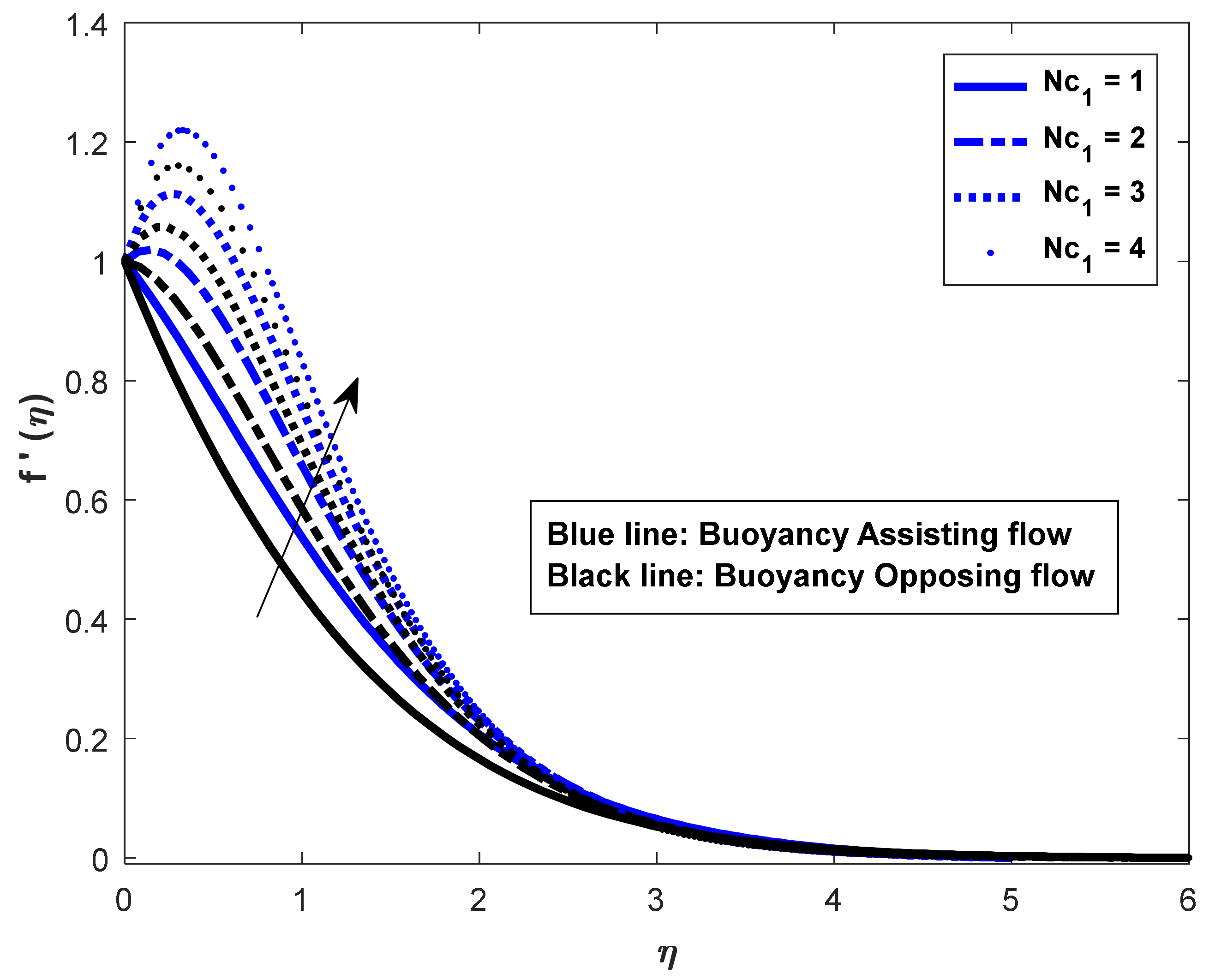
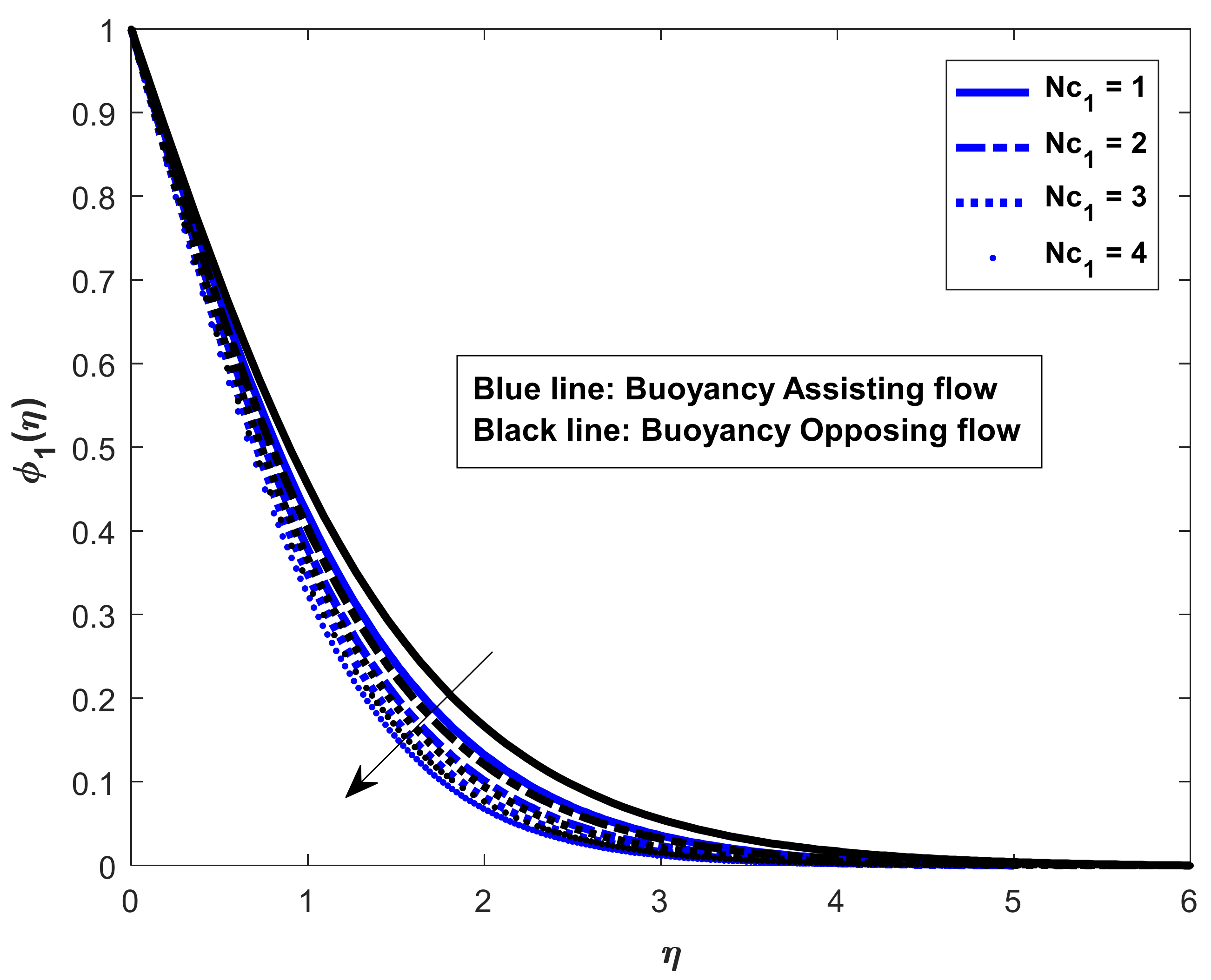
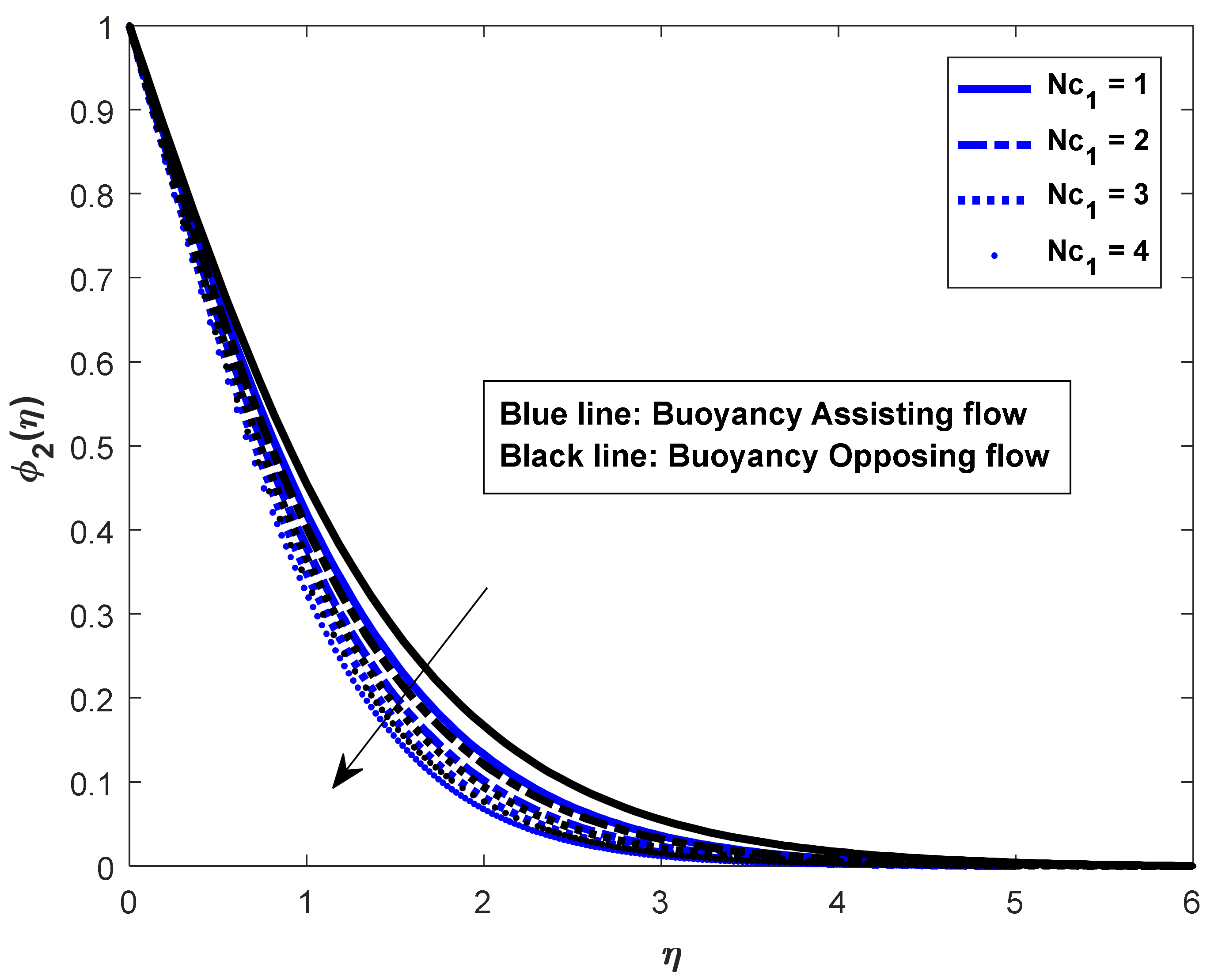
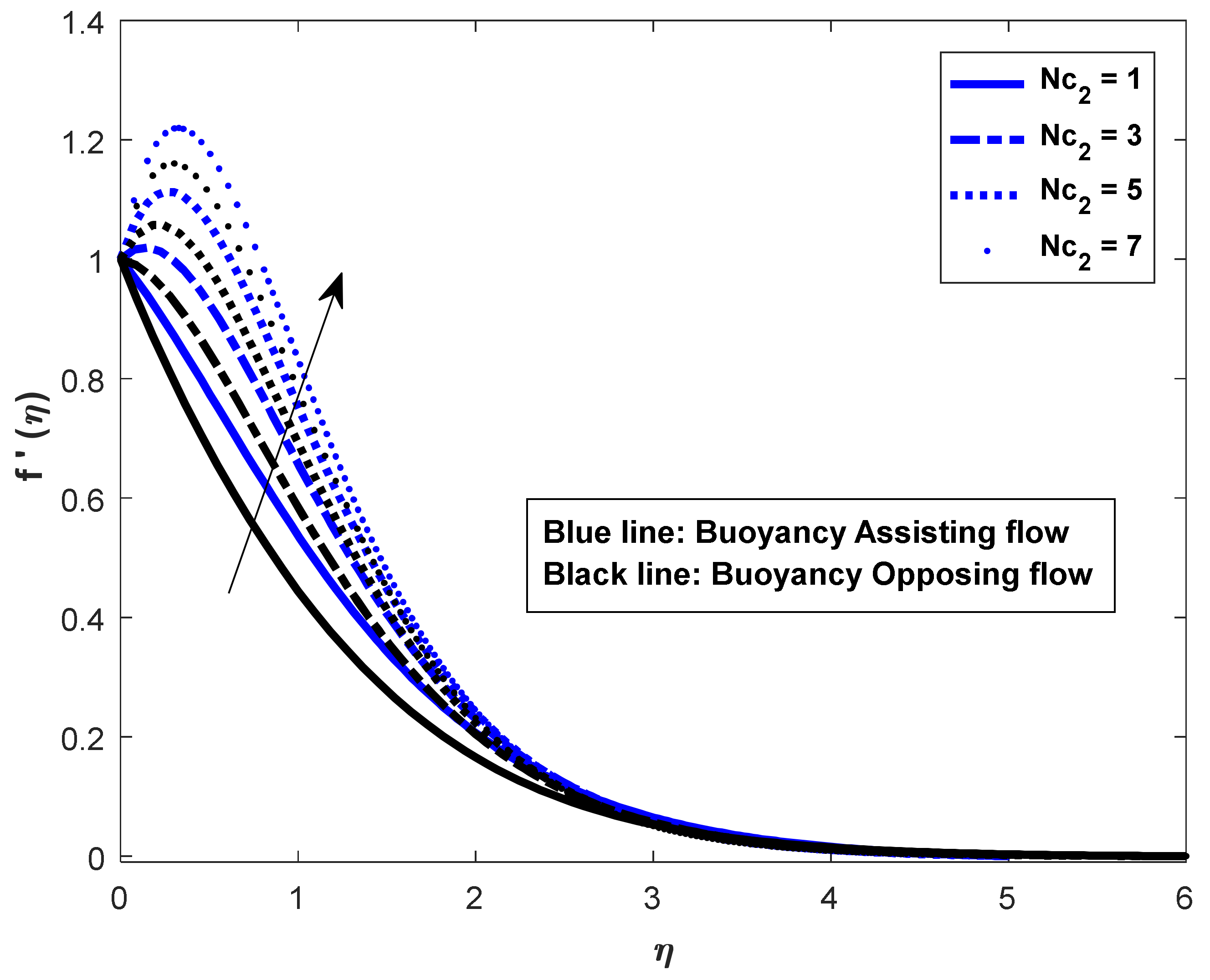
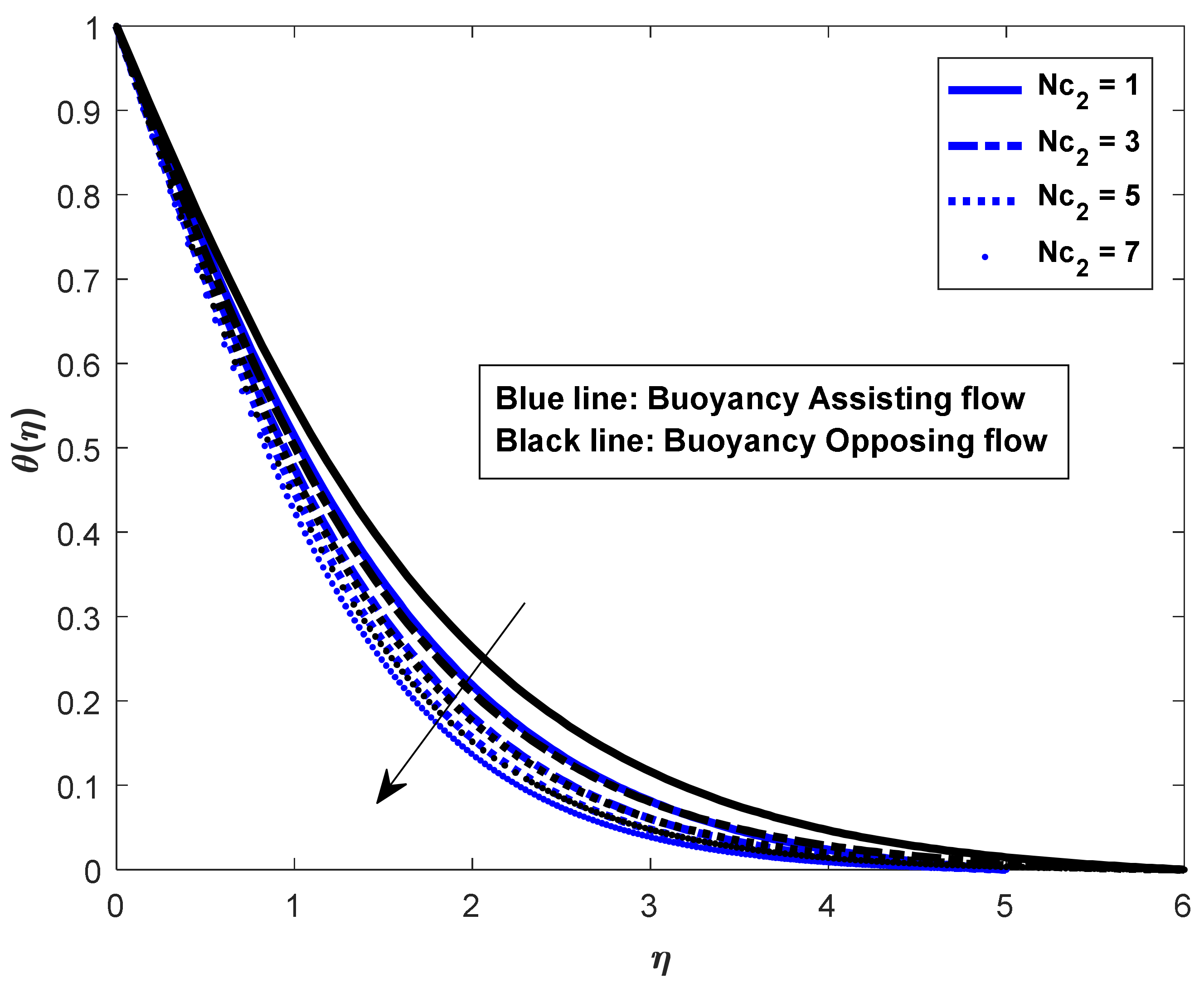
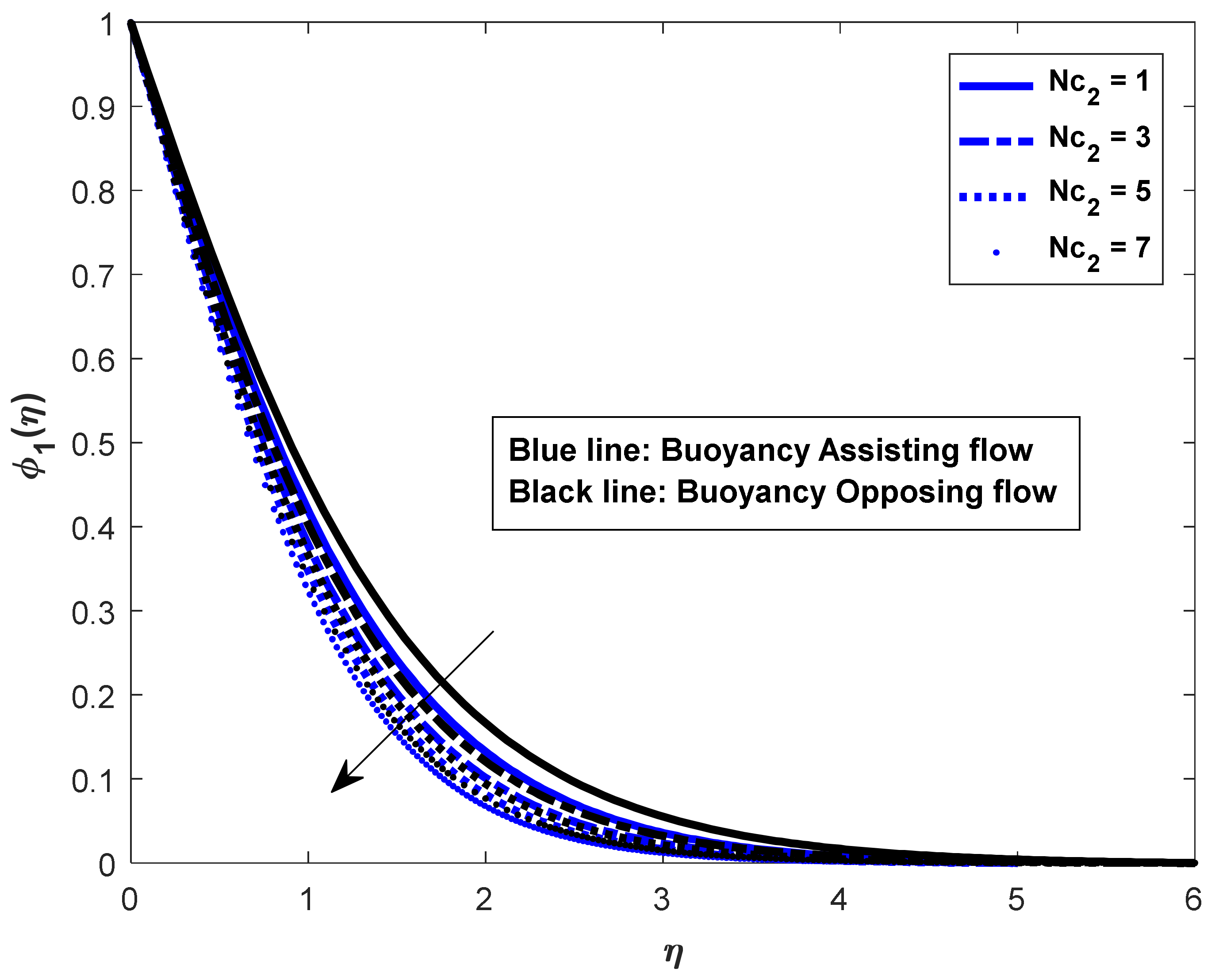
Figure 9, Figure 10, Figure 11, Figure 12, Figure 13, Figure 14, Figure 15 and Figure 16 illustrate the effects of buoyancy ratio parameters on velocity, temperature, and salt_1 and salt_2 concentration distributions. Increasing the values of buoyancy ratio parameters increases the velocity for smaller values of η , as shown in Figure 9 and Figure 13. From the graphical representations of Figure 10, Figure 11, Figure 12 and Figure 14, Figure 15, Figure 16 it is noticed that an increase in buoyancy ratio decreases the temperature and salt_1 and salt_2 concentration profiles in both assisting and opposing cases.
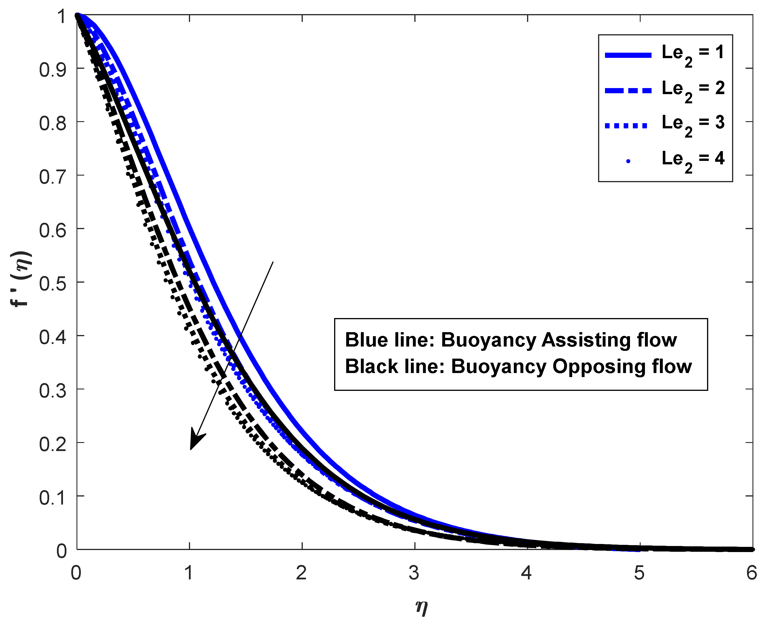
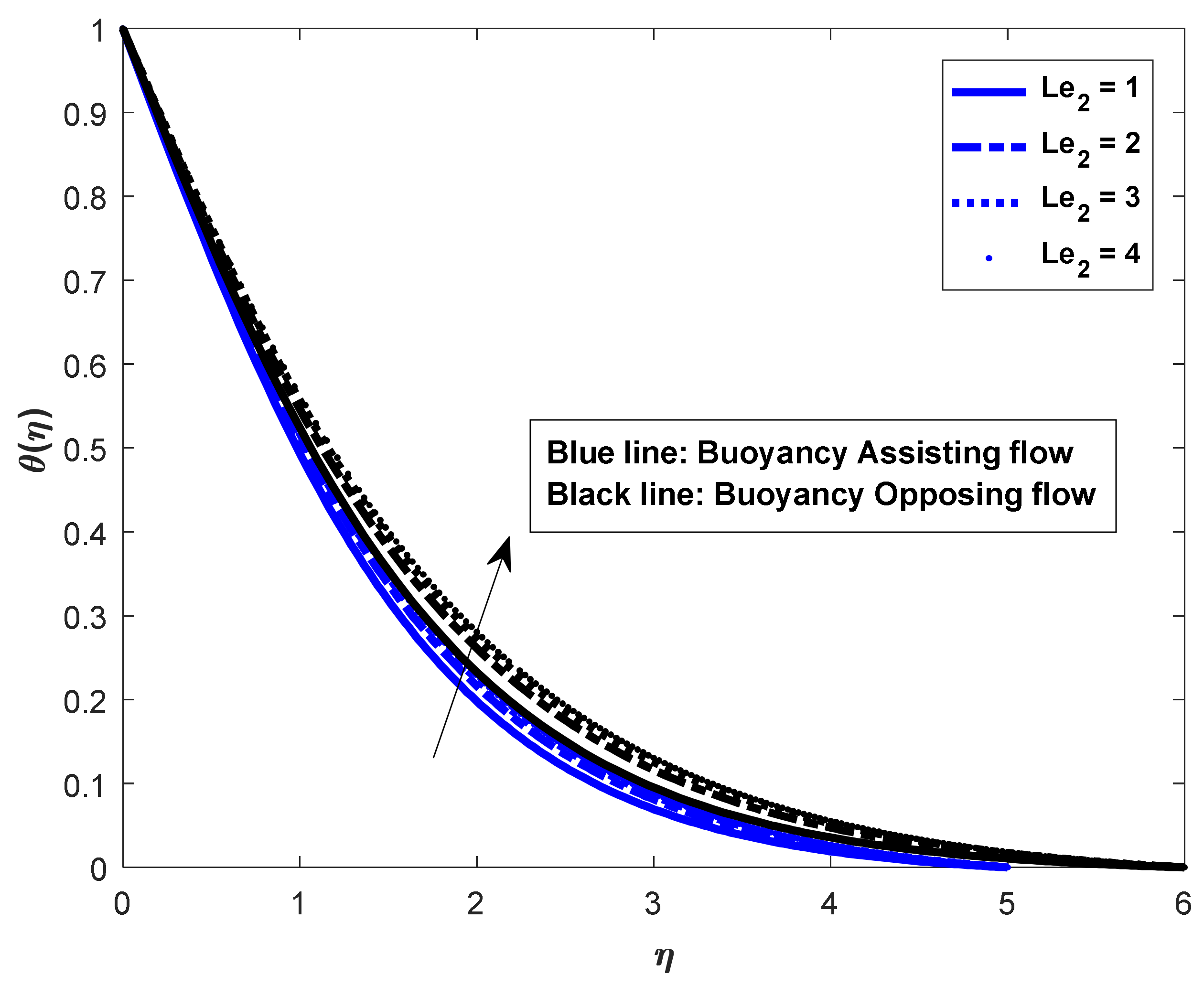
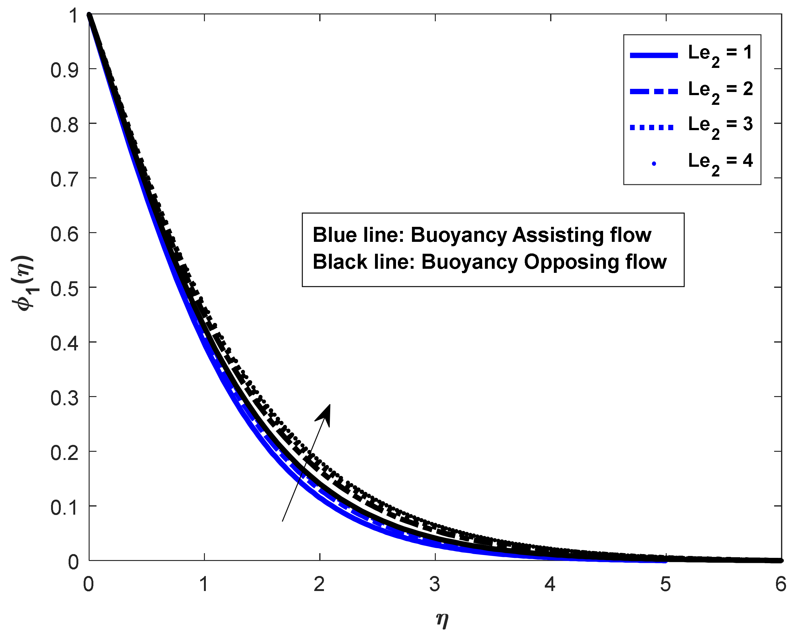
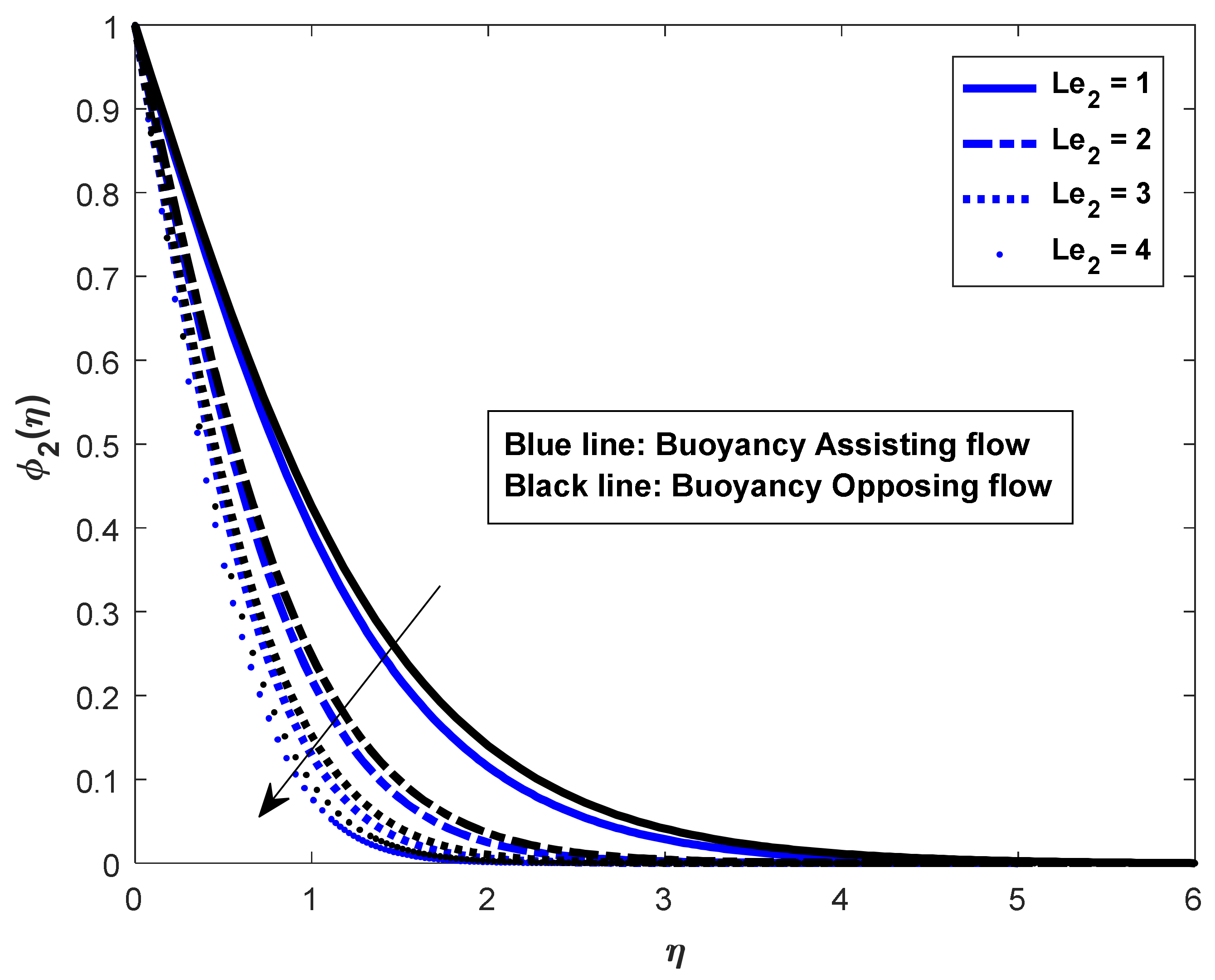
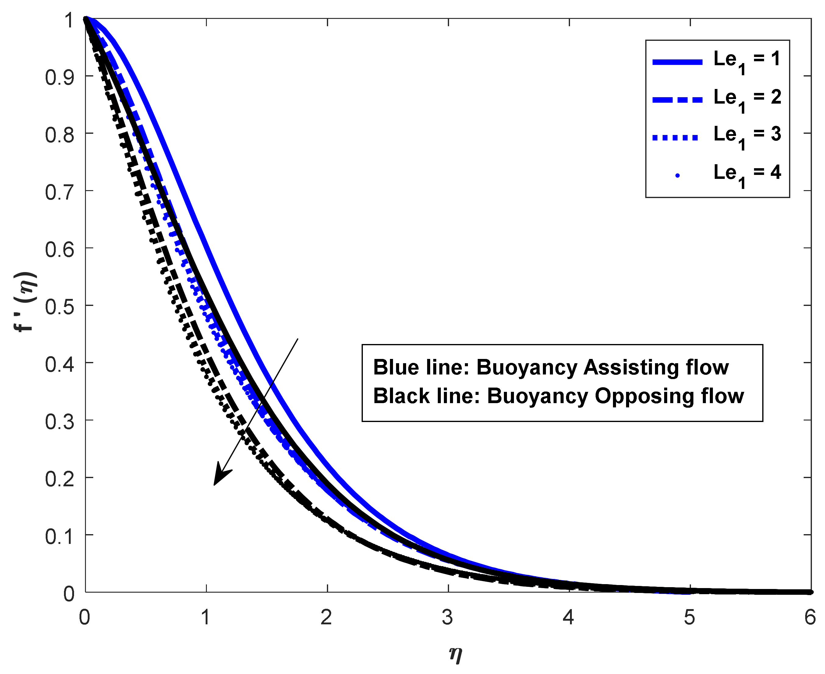
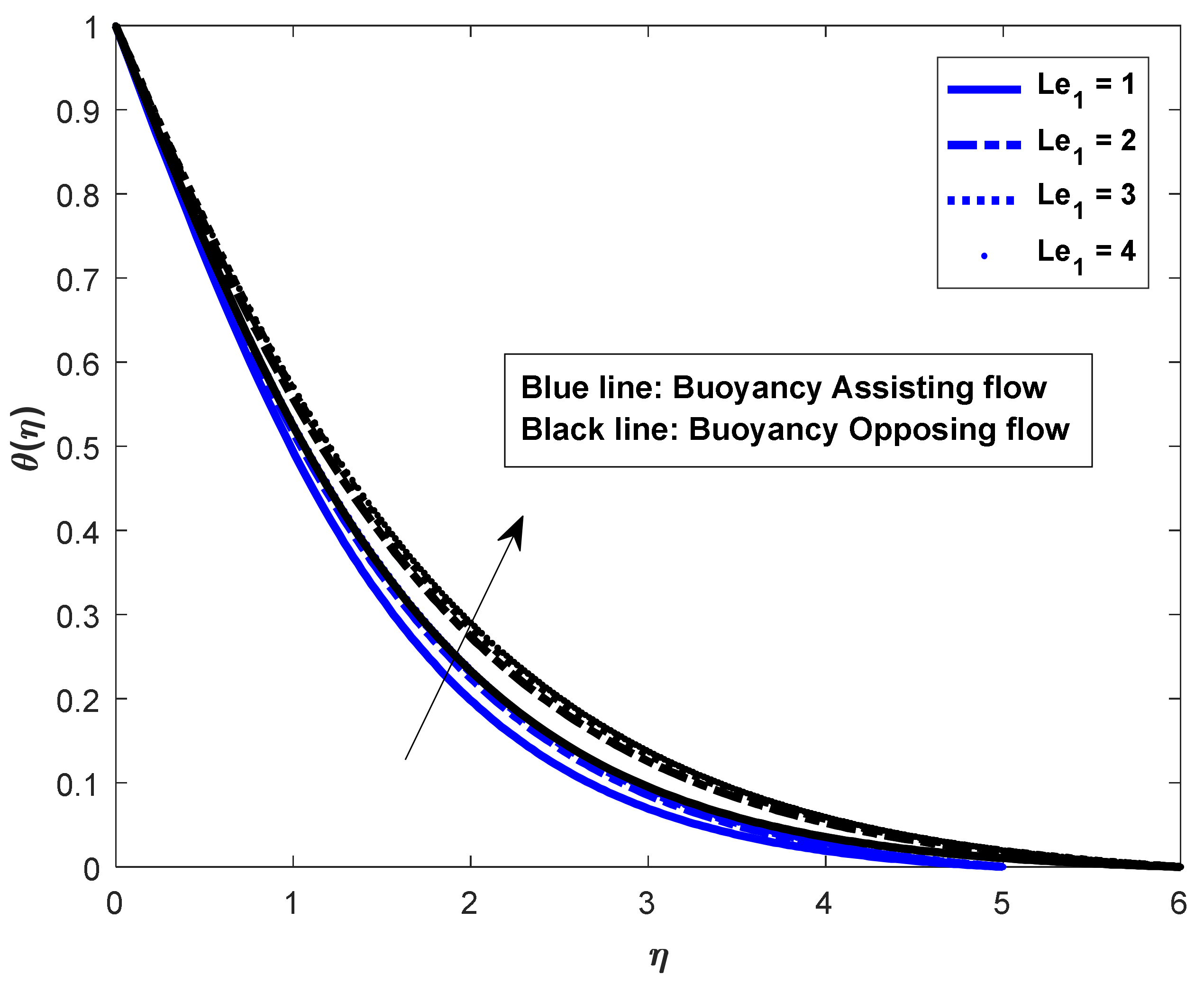
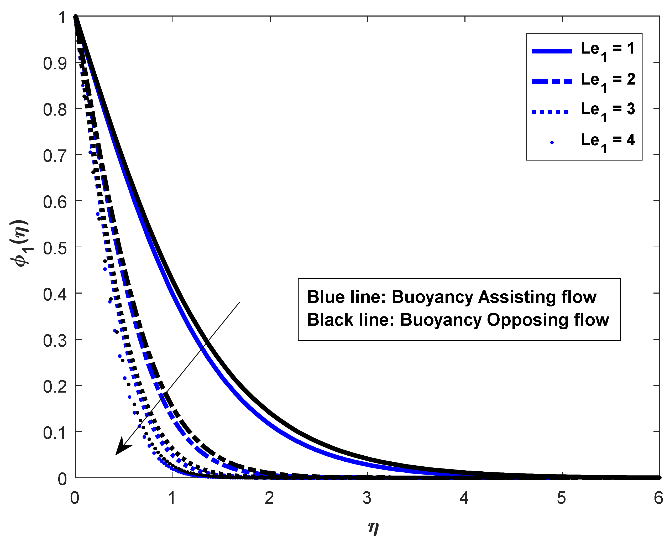
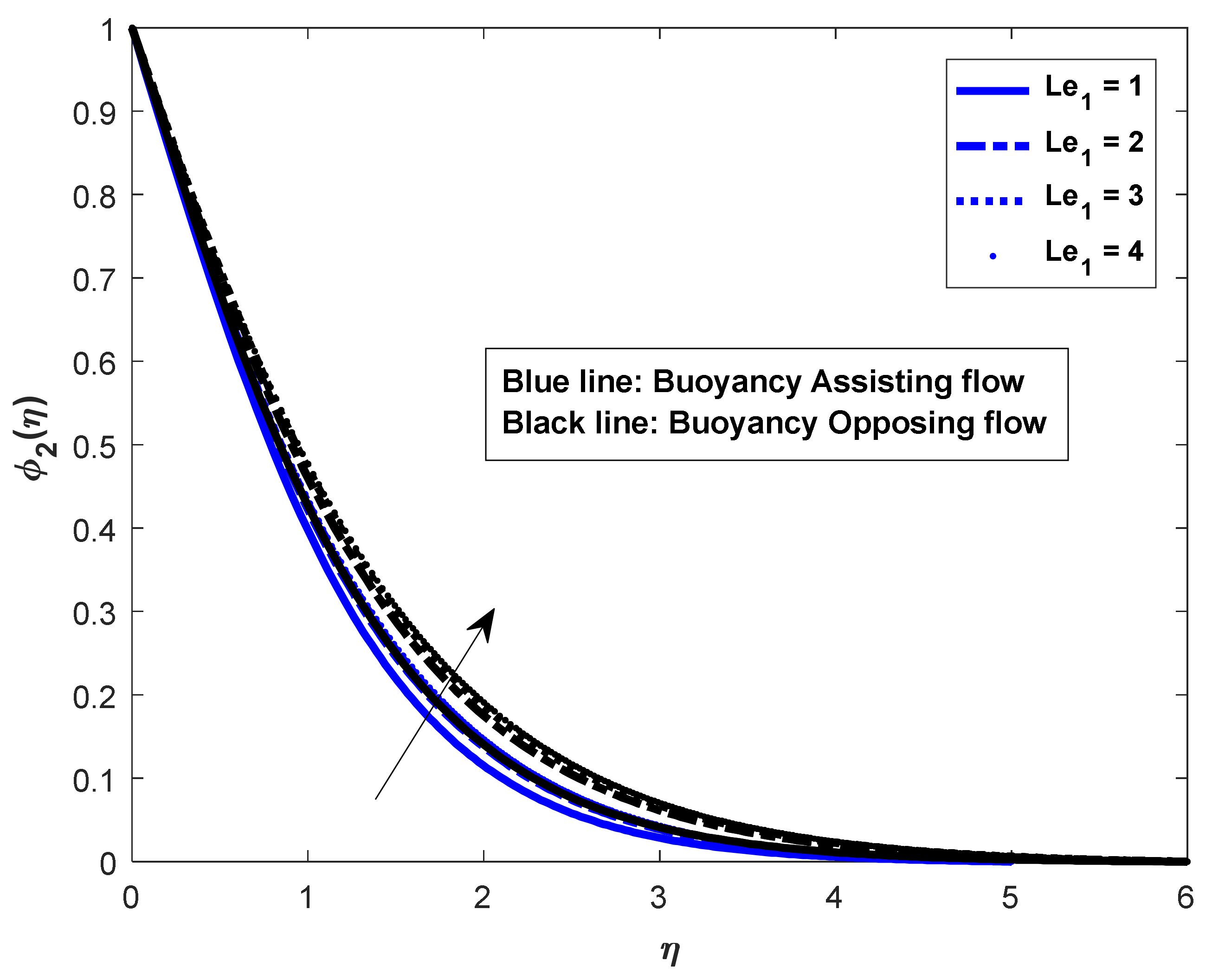
The velocity, temperature and concentration distributions f η ,   θ η ,   ϕ 1 η and ϕ 2 η for various values of Lewis numbers L e 2 and L e 1 can be observed in Figure 17, Figure 18, Figure 19, Figure 20, Figure 21, Figure 22, Figure 23 and Figure 24 for both the flow circumstances. In helping flows, the dimensionless concentration increases with increasing Lewis numbers inside the concentration boundary layer, whereas buoyancy opposes and resists flows. Lewis number determines the thickness of the concentration boundary layer physically. That is, the greater the Lewis number, the thinner the concentration boundary layer will be. For Lewis numbers, the dimensionless wall concentrations decline quickly to zero in both buoyancy assisting and opposing flows, and the inside wall concentration is equivalent to the ambient concentration. In fluid flow instances, the thickness of the thermal boundary layer decreases while the momentum boundary layer increases.
It is recognized that the friction factor rate was enhanced in both flow cases for an increase in Lewis numbers L e 1 and L e 2 . However, the influences of θ 0 ,   ϕ 1 0 , ϕ 2 0 decreased in both the flow cases with an increase in Lewis number. The friction factor coefficient decreased with increases in buoyancy ratio parameters N c 1 and N c 2 , but the opposite behavior was observed in the cases of Nusselt and Sherwood numbers. The skin friction coefficient increased for an increase in magnetic field parameter, whereas the opposite phenomena could be observed in both cases’ mass and heat transfer rates. Finally, the Prandtl number increased the friction factor in assisting flow and decreased it in opposing flow. The same behavior can also be observed ϕ 2 0 in both the assisting flow ( λ > 0 ) and opposing flow ( λ < 0 ) cases.
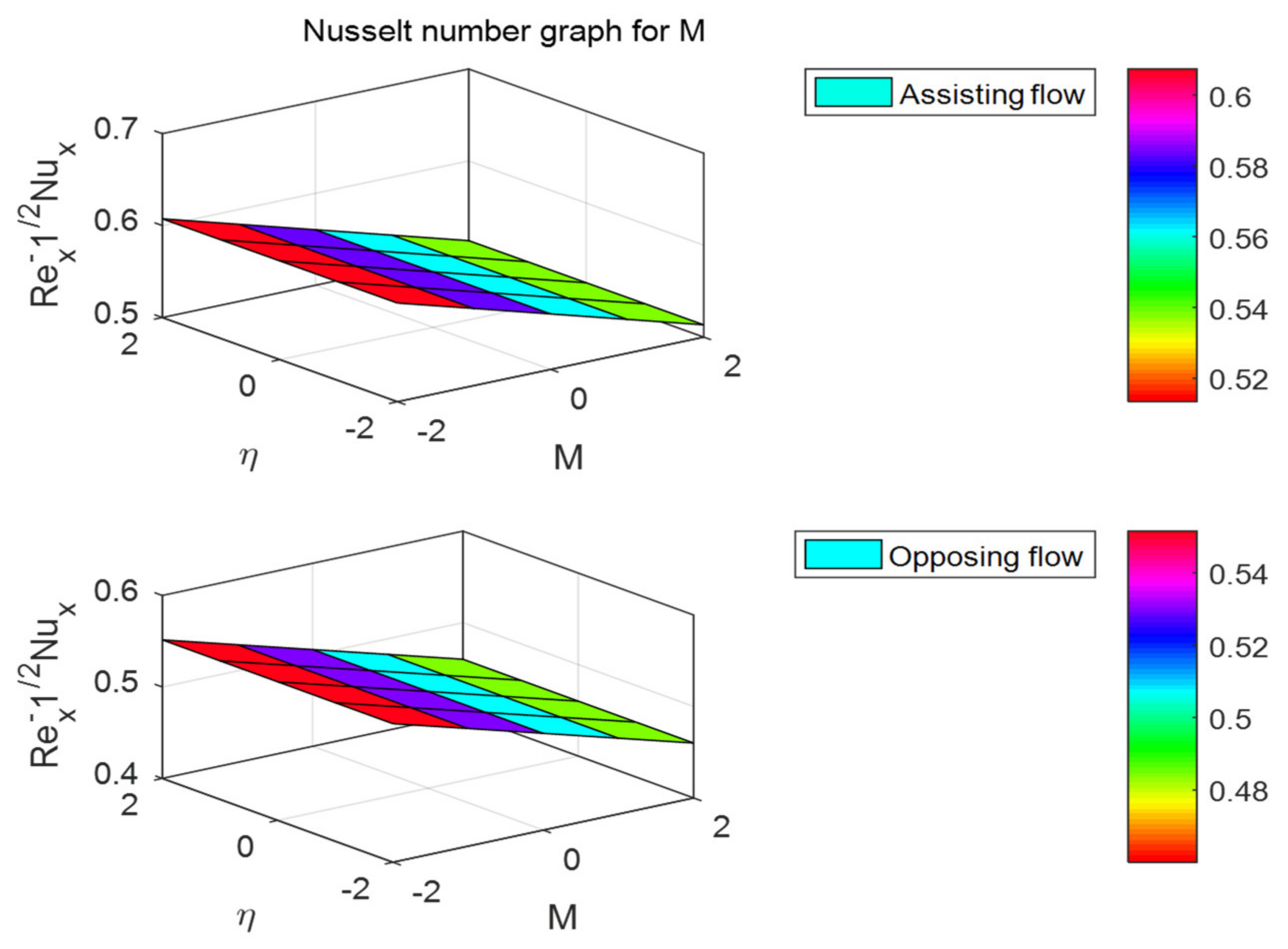
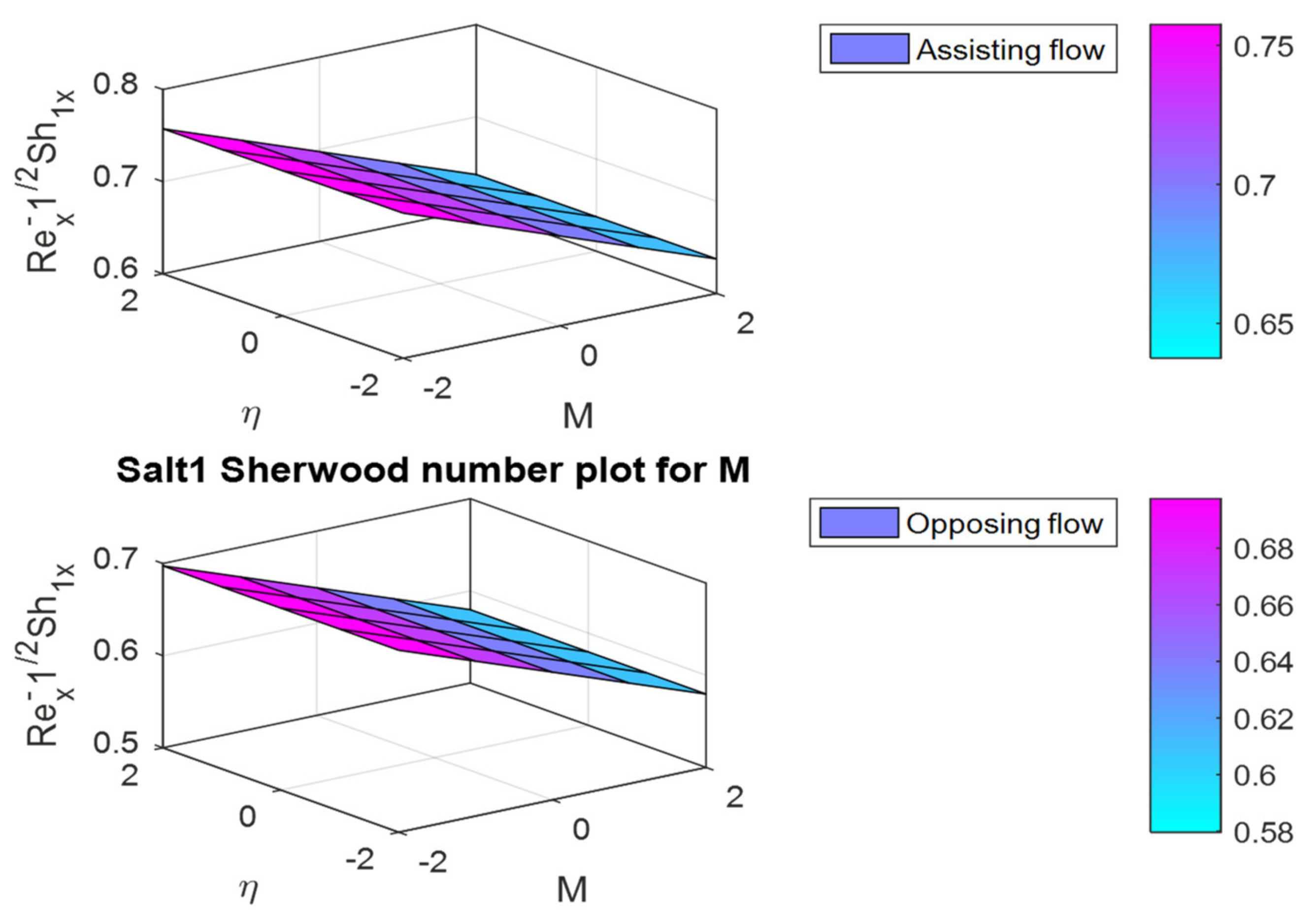
The f 0 ,   θ 0 and ϕ 0 plots for different values of the magnetic field parameter M are shown in Figure 25, Figure 26 and Figure 27. Figure 25 shows that as the value of M increases, f 0 is enhanced at a rate of 0.290386 ( λ > 0 ) or 0.26876 ( λ < 0 ) . Similarly, for assisting and opposing flows, heat and mass transfer coefficients decrease at rates of −0.0235 and −0.02999, and −0.02286 and −0.02946, respectively. Due to the buoyancy force, surface shear stress is greater in assisting flow than in opposing flow.
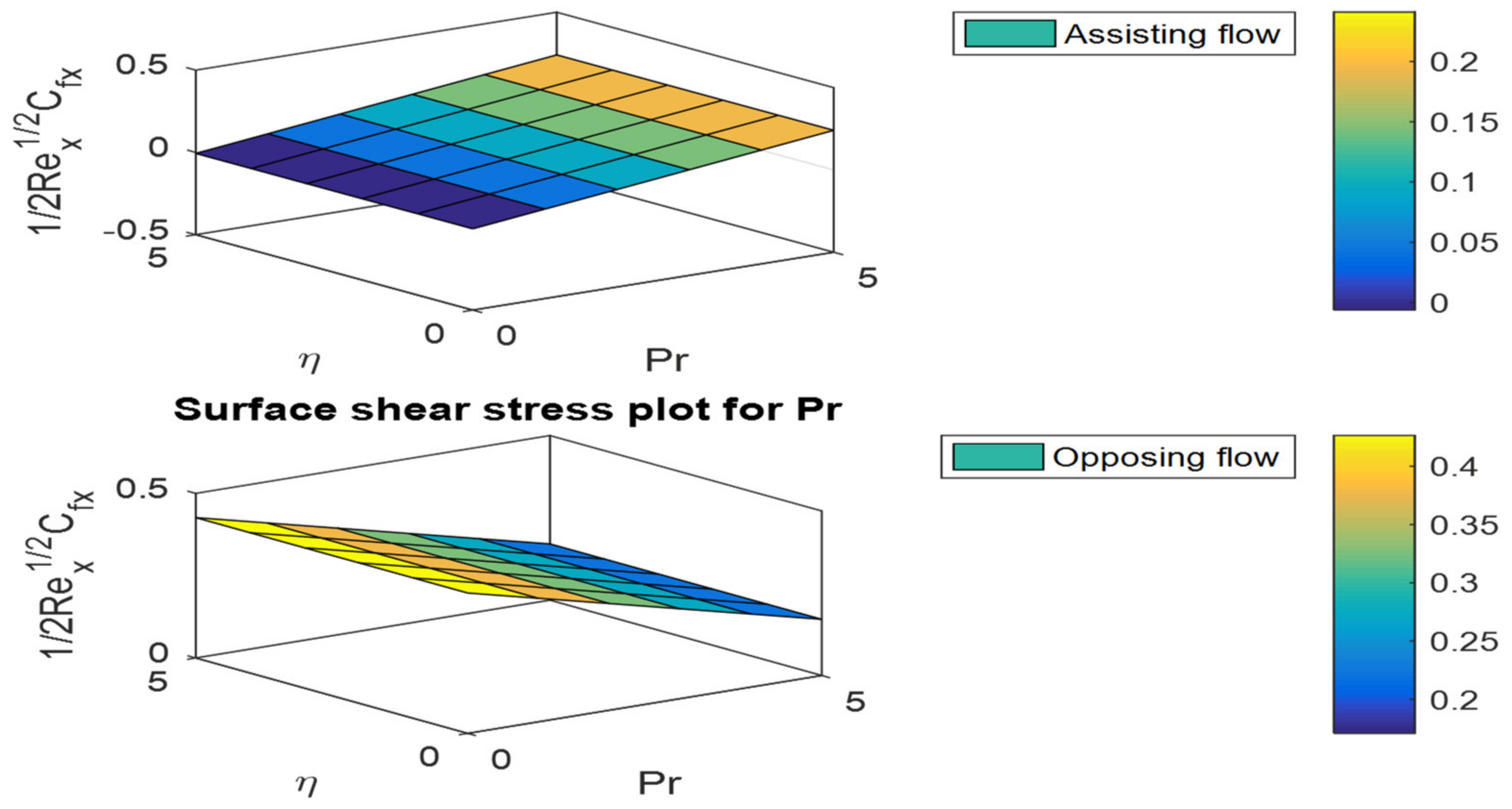
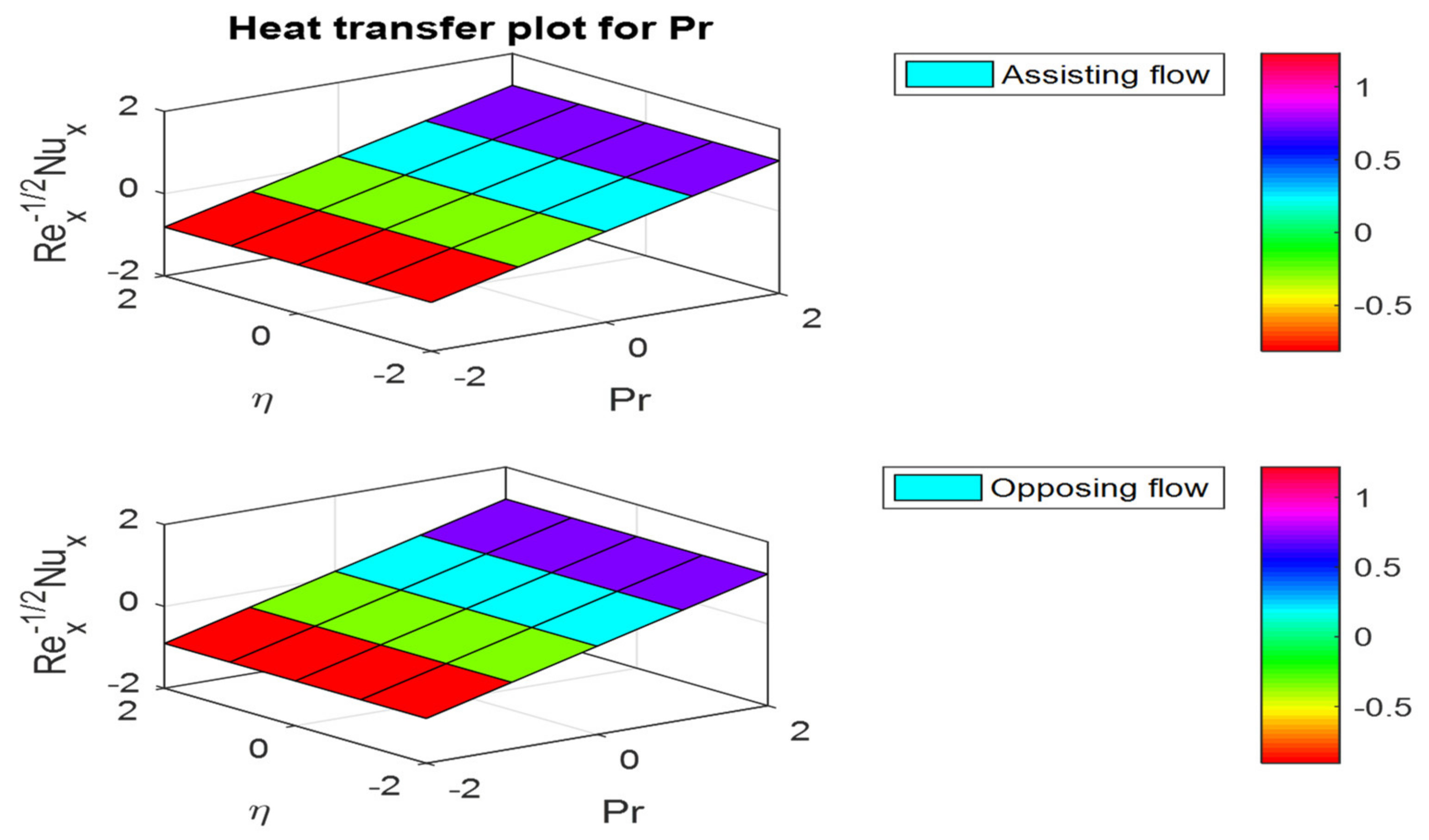
The skin friction coefficient θ 0 and ϕ 0 plots for different Pr values are shown in Figure 28, Figure 29 and Figure 30. As Pr grows, f 0 increases in assisting flow and falls in opposing flow, as seen in Figure 28. The Sherwood number ϕ 0 exhibits opposite behavior (Figure 30). However, in both fluid flow cases, θ 0 is increased (Figure 29).
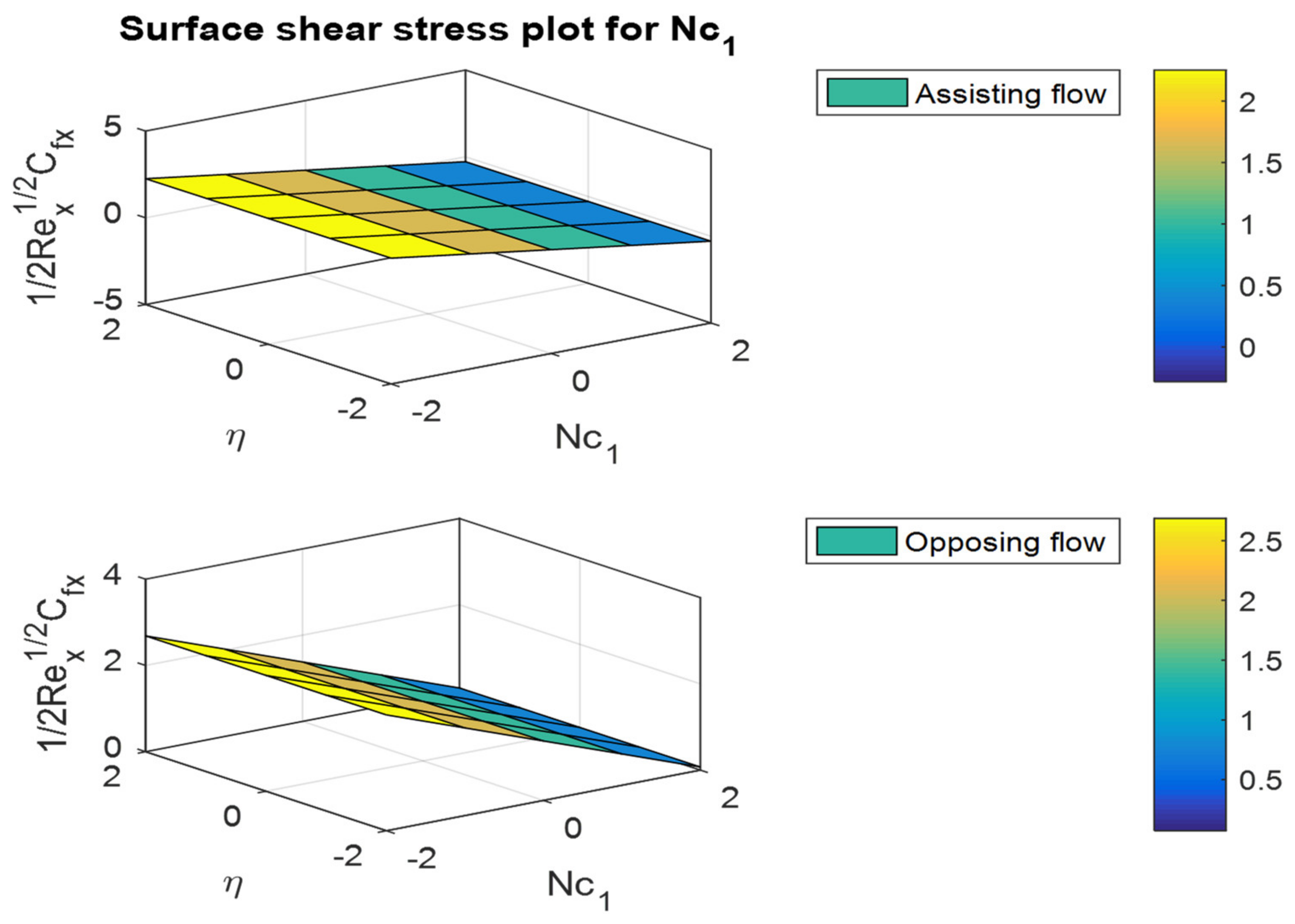
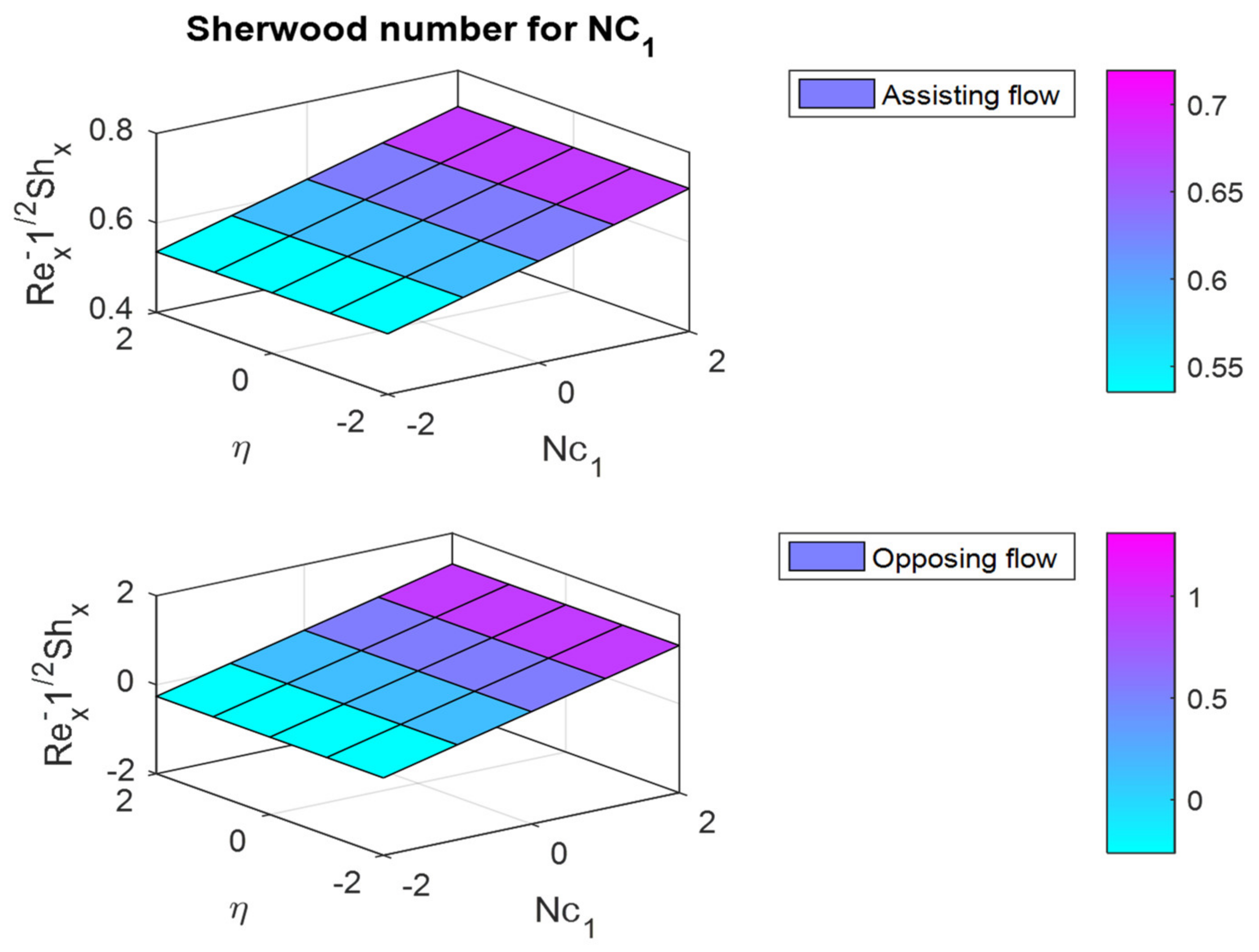
Figure 31, Figure 32 and Figure 33 depict the friction factor coefficient, θ 0 , and ϕ 0 plots for different values of N c 1 . Figure 31 represents that for increasing values of N c 1 , the friction factor coefficient decreases in assisting and opposing flow cases. The rates of θ 0 and ϕ 0 rise as the Prandtl number increases in both cases.
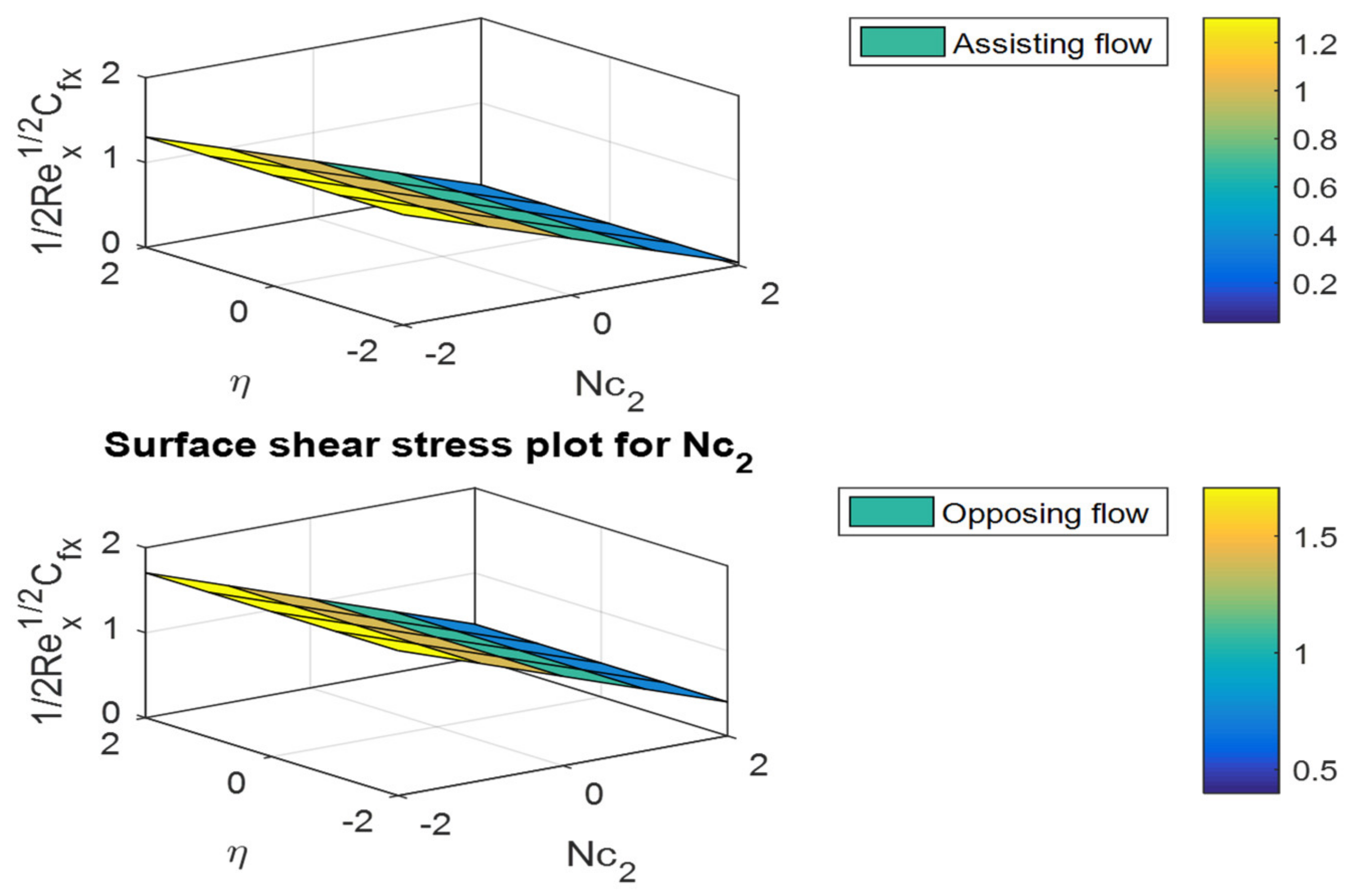
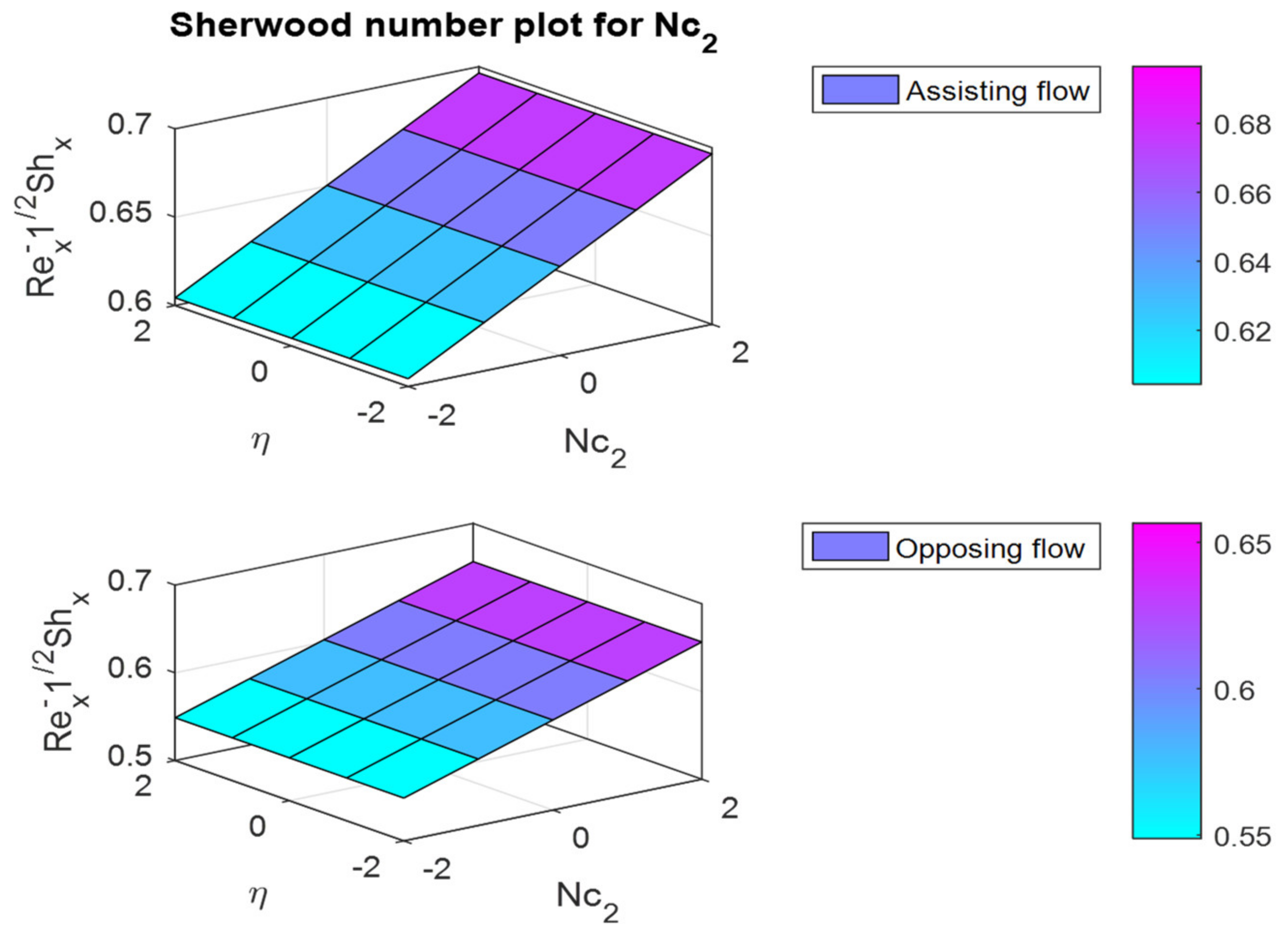
The f 0 ,   θ 0 and ϕ 0 plots for various values of the buoyancy ratio parameter N c 2 are shown in Figure 34, Figure 35 and Figure 36. Figure 34 shows that when N c 2 increases, the skin friction coefficient decreases at a rate of −0.31689 ( λ > 0 ) or −0.32663 ( λ < 0 ) . For assisting and opposing flow, the Nusselt and Sherwood numbers escalate rates of 0.019164 and 0.022813, and 0.022813 and 0.026919, respectively.
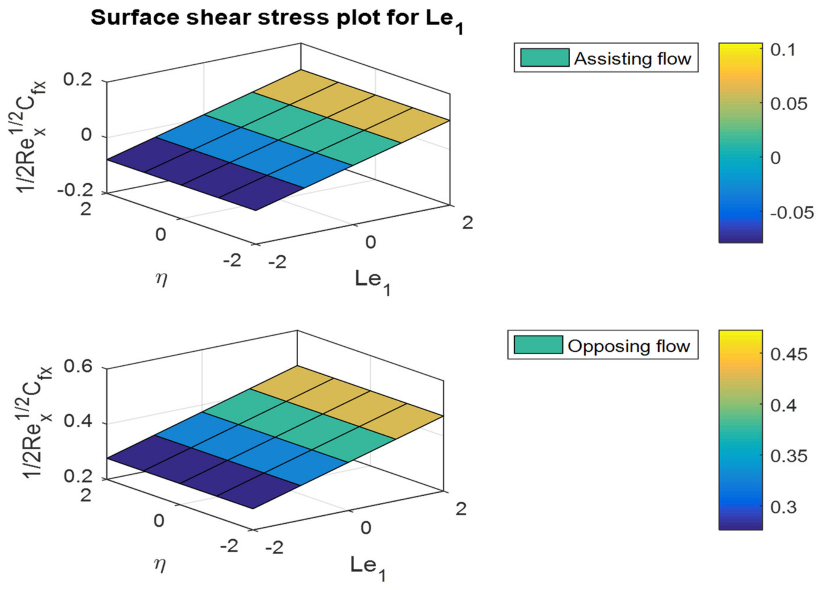
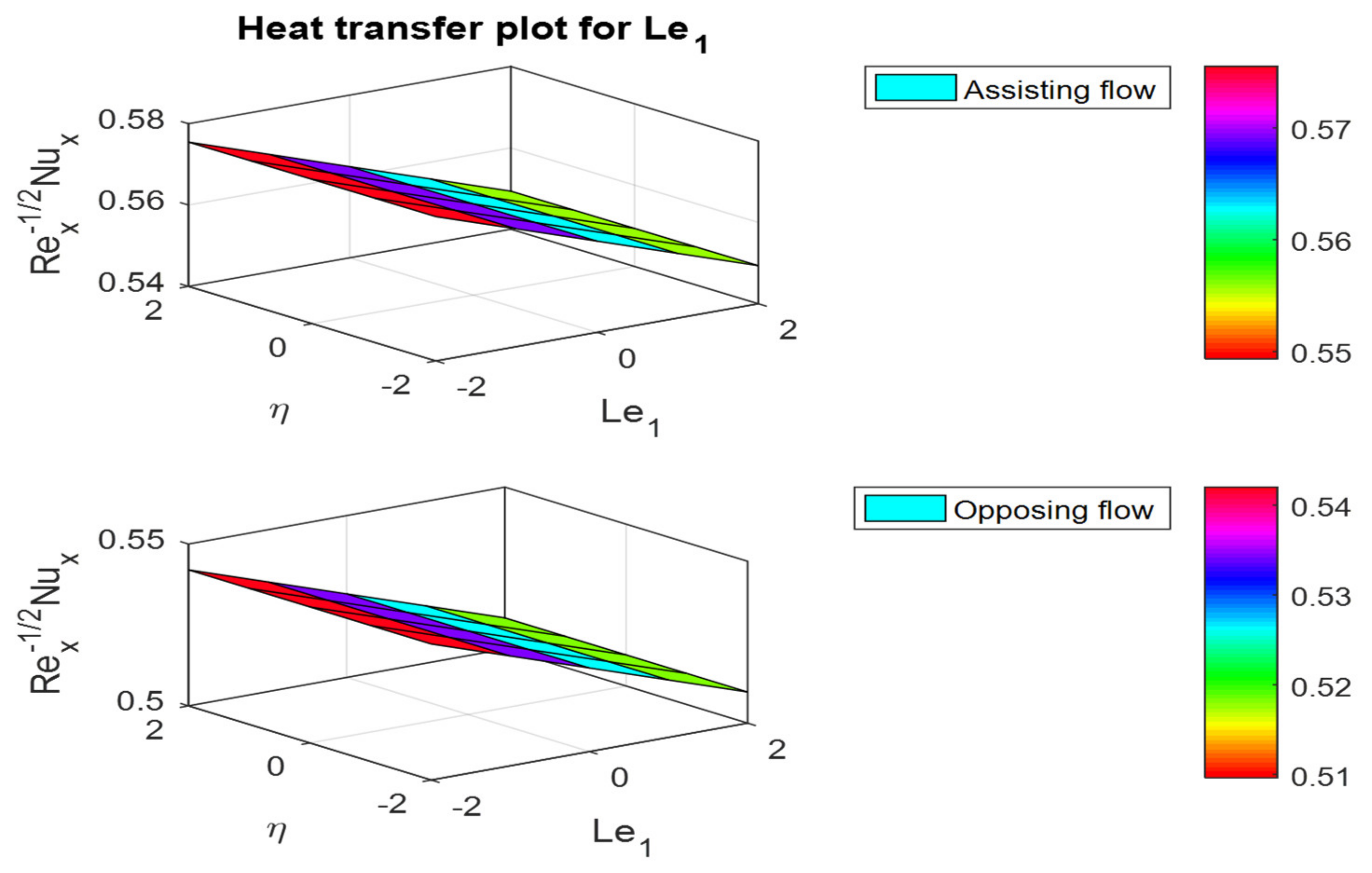
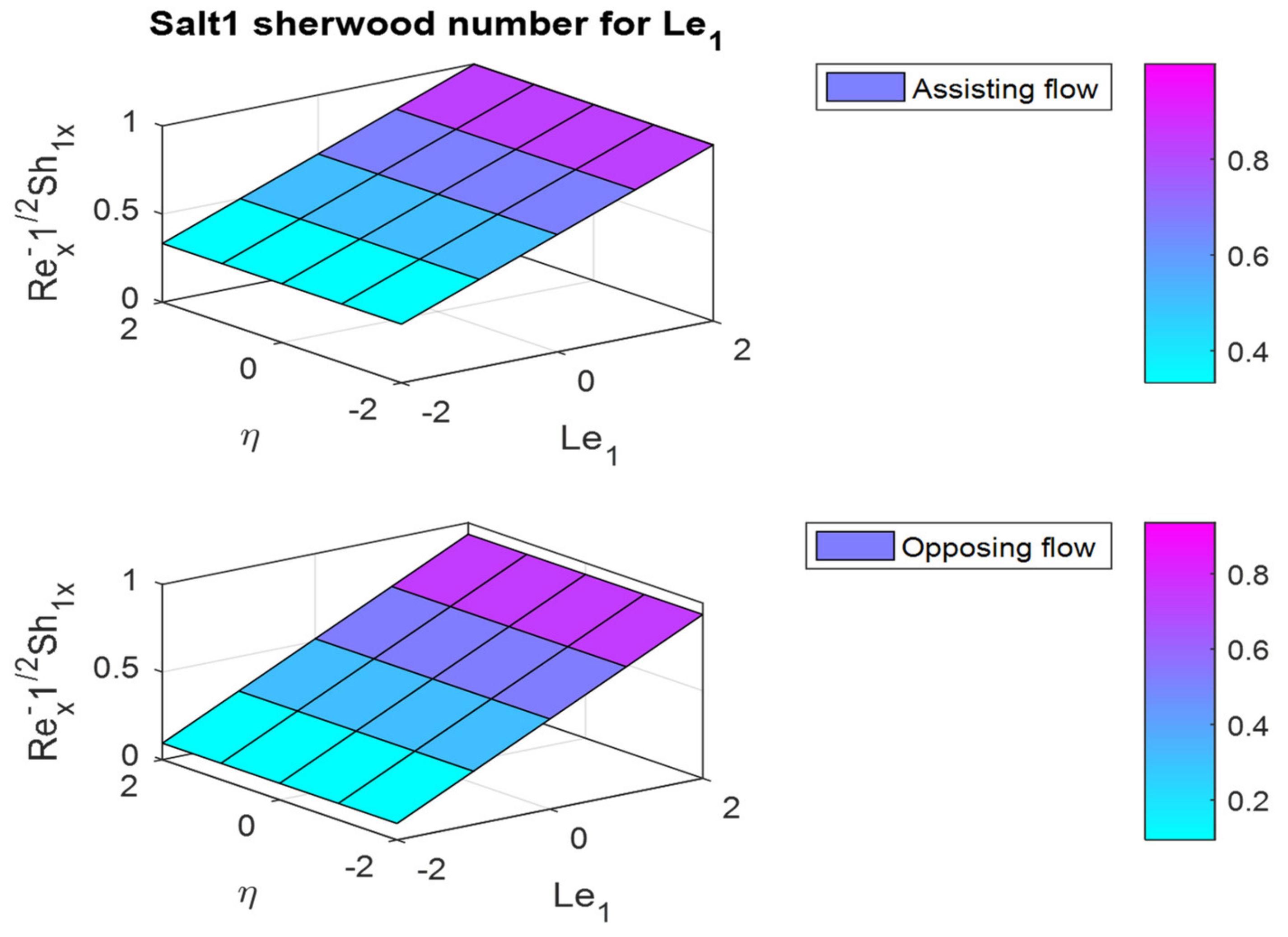
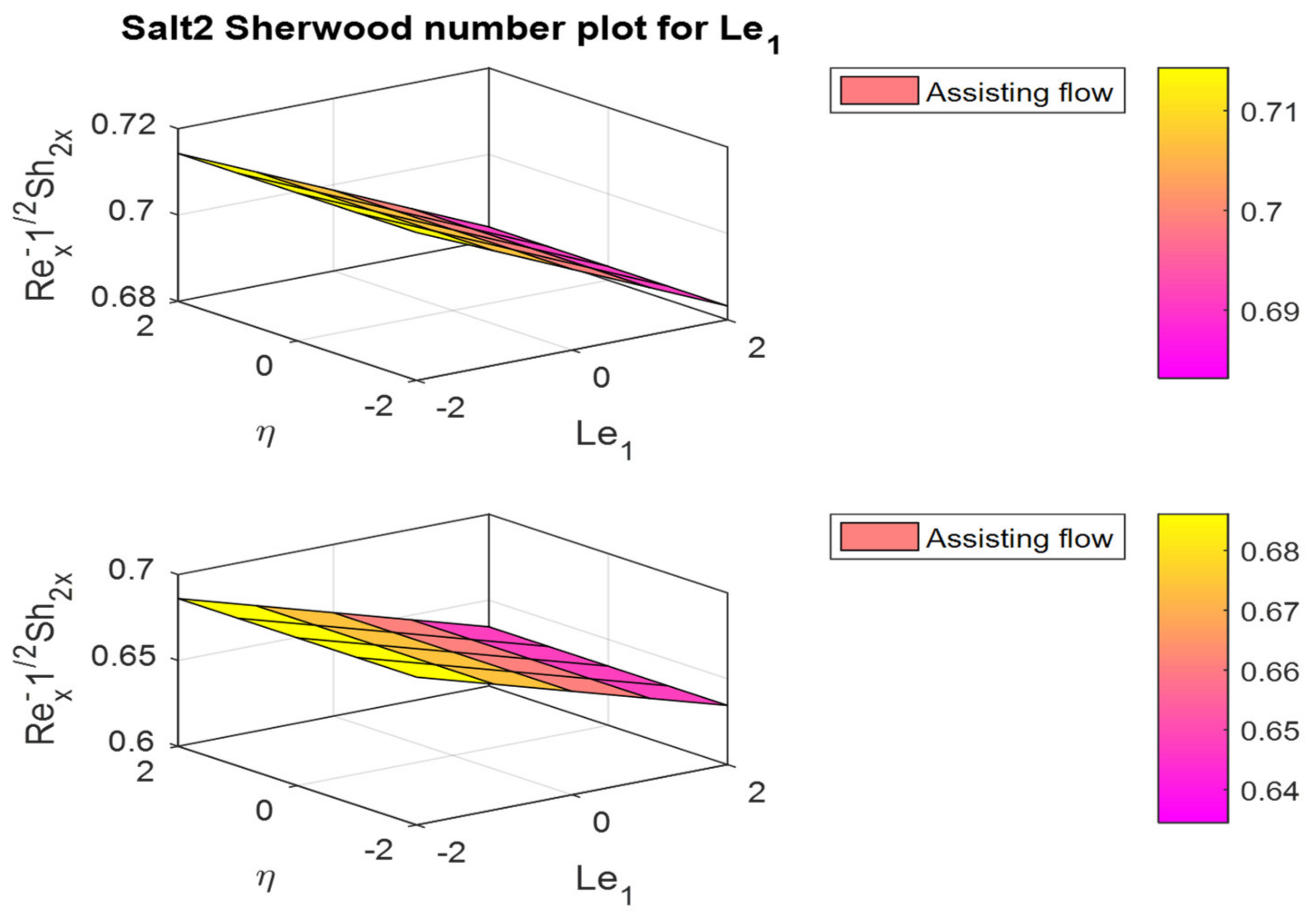
Figure 37, Figure 38, Figure 39 and Figure 40 illustrate the shear stress, Nusselt number, and salt_1 and salt_2 Sherwood number plots for different values of Lewis number L e 1 . Figure 37 shows that for increasing values of L e 1 , the skin friction coefficient increases at 0.045962 (assisting flow) and 0.048975 ( λ < 0 ) rates. The θ 0 is decreased at the rates of −0.00653 and −0.00881 in the fluid flow cases. The salt_1 Sherwood number for the Lewis number is increased in assisting and opposing flow cases, whereas the reverse trend can be observed for salt_2 Sherwood in both cases.
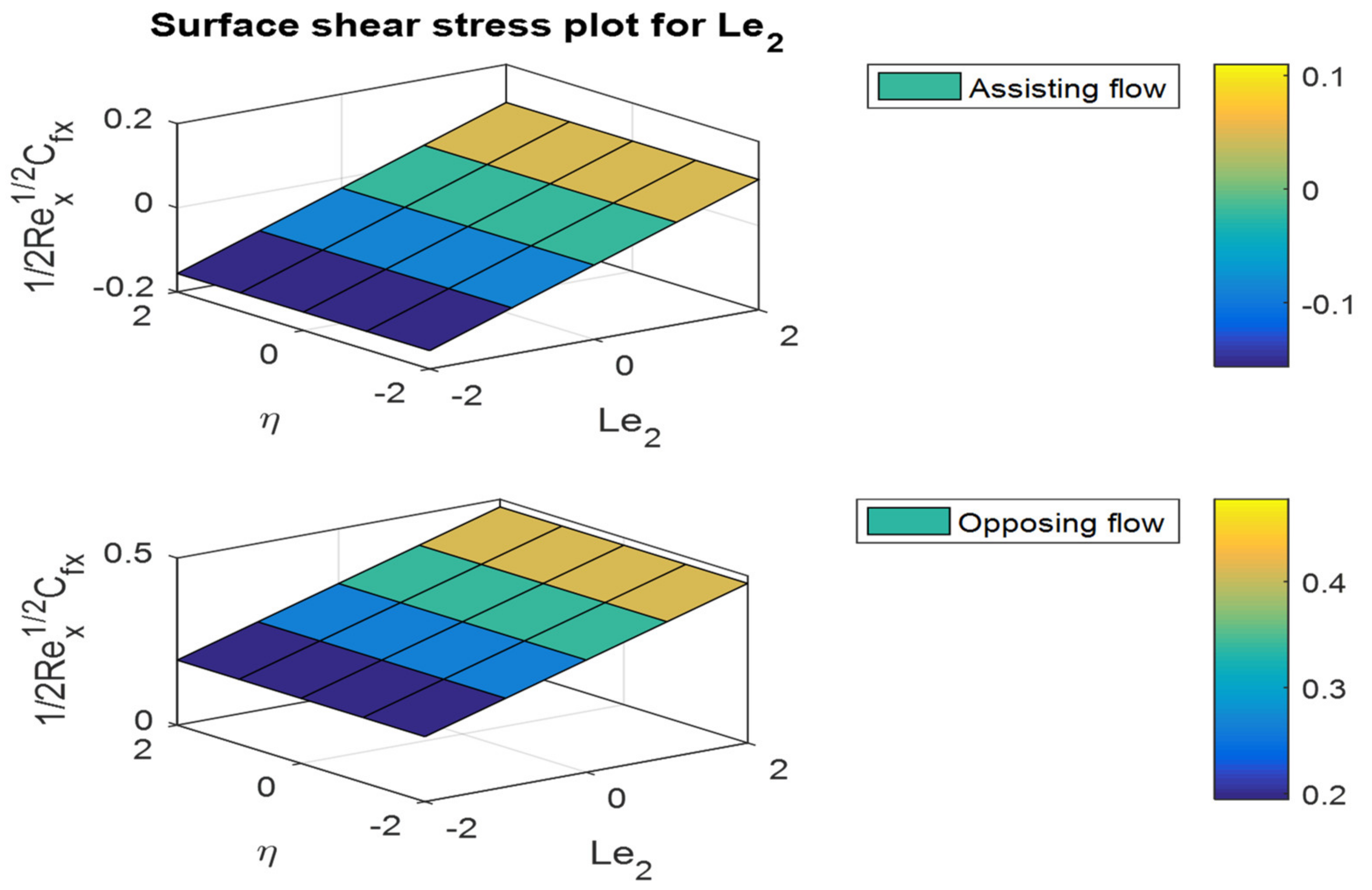
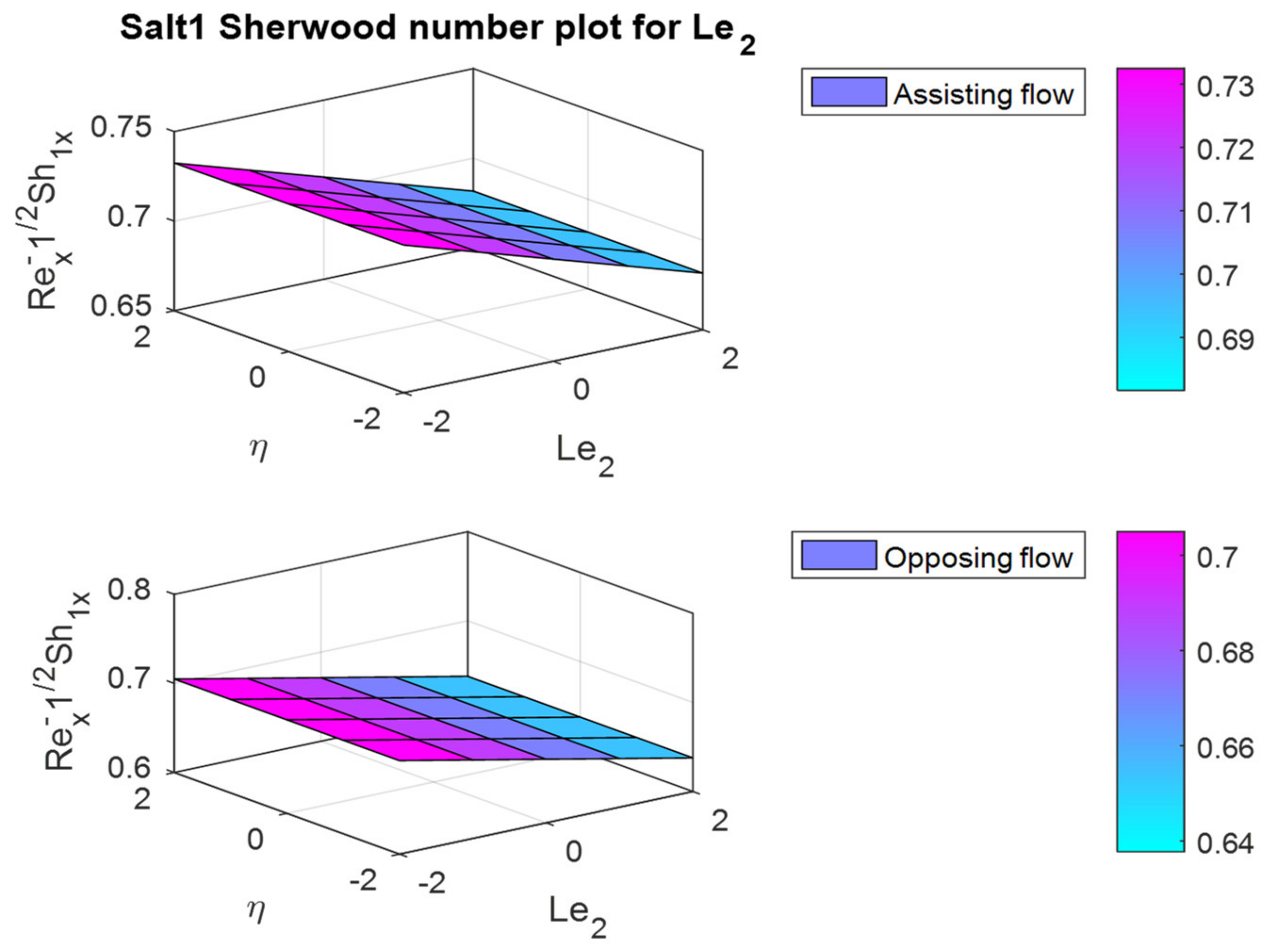
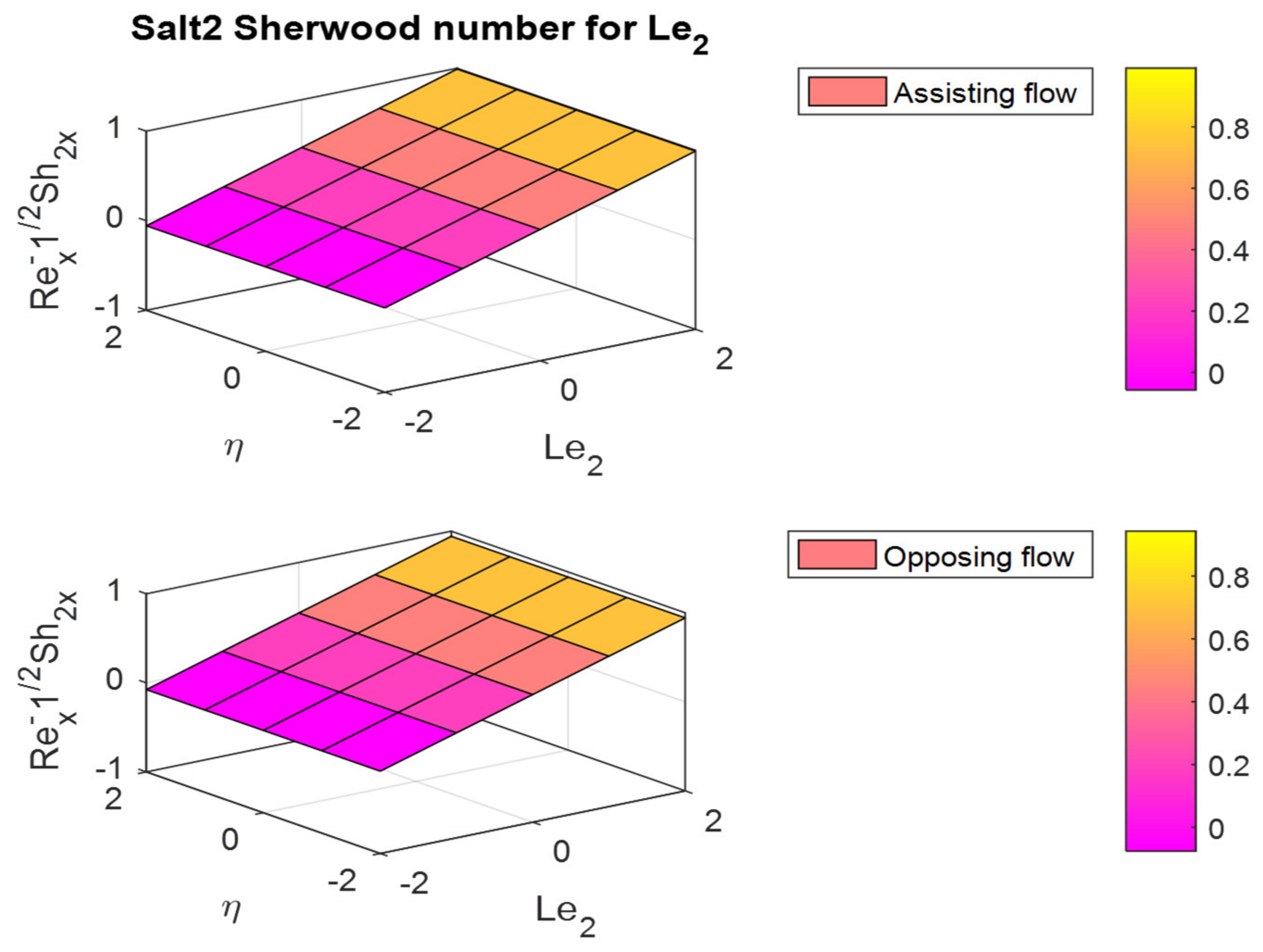
Figure 41, Figure 42, Figure 43 and Figure 44 illustrate the shear stress, Nusselt number, and salts_1 and salt_2 Sherwood number plots for different values of Lewis number L e 2 . Figure 41 shows that increasing values of L e 2   f 0 escalate in both fluid flow cases. The Nusselt number is decreased in both flow cases. Finally, the salt_1 Sherwood number decreased and the salt_2 Sherwood number increased in both assisting and opposing flow cases.

5. Concluding Remarks

A steady, incompressible, and laminar boundary layer was used to investigate the effects of triple diffusion on boundary layer flow, heat, and mass transfer through a linearly stretching sheet. Numerical findings for surface θ 0 and ϕ 0 were provided for various values of the governing parameters. The following are the investigation’s principal findings:
  • The friction factor rate is enhanced in both fluid flow cases for increases in Lewis numbers L e 1 and L e 2 .
  • The friction factor coefficient decreases with increases in buoyancy ratio parameters N c 1 and N c 2 , but the opposite behavior can be observed for the Nusselt and Sherwood numbers.
  • In the assisting flow case, the dimensionless concentration rises as the Lewis number rises; for buoyancy, the opposing flow case also remains the same.
  • The magnetic field parameter decreased the velocity distribution by the effect of Lorentz force.
  • In both assisting and opposing flow instances, the Prandtl number increases the skin friction coefficient in assisting flow and decreases it in opposing flow in heat and mass transfer rates.

6. Limitations and Future Scope

6.1. Limitations

  • The flow was considered as not time-dependent and incompressible.
  • The turbulence due to the hematite nanoparticles interaction was neglected.
  • Away from the object’s surface, viscous effects can be considered negligible, and potential flow can be assumed.
  • The viscosity, conductivity, and density properties were constant.

6.2. Future Scope

  • Triple diffusion analysis can include variable viscosity and nonlinear convection flow properties.
  • Variable conductivity and unsteady nonlinear flow characteristics of various flow characteristics with chemical species in the triple diffusion process.
  • The investigations mentioned above could also be extended by using various techniques, such as mess-free methods, the finite-difference scheme, the spectral element method, the finite element method, the Keller-box method, homotopy analysis, and spectral methods.

Author Contributions

Conceptualization, V.N. and P.D.; methodology, V.N. and N.S.; software, P.D. and B.M.R.; validation, S.-J.Y.; formal analysis, C.S.K.R.; investigation, C.S.K.R. and S.-J.Y.; resources, N.A.S.; writing—original draft preparation, V.N., P.D. and C.S.K.R.; writing—review and editing, N.S., B.M.R., N.A.S. and S.-J.Y.; Project administration, C.S.K.R. and N.A.S.; funding, S.-J.Y. All authors have read and agreed to the published version of the manuscript.

Funding

This research received no external funding.

Institutional Review Board Statement

Not applicable.

Informed Consent Statement

Not applicable.

Data Availability Statement

The numerical data used to support the findings of this study are included within the article.

Conflicts of Interest

The authors declare no conflict of interest.

References

  1. Rohsenow, W.; Hartnett, J.; Cho, Y. Handbook of Heat Transfer, 3rd ed.; Mcgraw-Hill: New York, NY, USA, 1998; ISBN 9780070535558. [Google Scholar]
  2. Bird, B.; Stewart, W.; Lightfoot, E.; Edwin, N. Transport Phenomena, 2nd ed.; John Wiley: New York, NY, USA, 2002; p. 895. ISBN 0-471-41077-2. [Google Scholar]
  3. Animasaun, I.L.; Shah, N.A.; Wakif, A.; Mahanthesh, B.; Sivaraj, R.; Koriko, O.K. Ratio of Momentum Diffusivity to Thermal Diffusivity: Introduction, Meta-Analysis, and Scrutinization, 1st ed.; Chapman and Hall/CRC: Boca Raton, FL, USA, 2022. [Google Scholar]
  4. Priest, E.R. Solar Magnetohydrodynamics; Cambridge University Press: Cambridge, UK, 2003. [Google Scholar]
  5. Laughlin, D.R. A Magnetohydrodynamic Angular Motion Sensor for Anthropomorphic Test Device Instrumentation. J. Passeng. Cars 1989, 98, 1648–1682. [Google Scholar]
  6. Jang, J.; Lee, S.S. Theoretical and Experimental Study of MHD (Magnetohydrodynamic) Micropump. Sens. Actuators A Phys. 2000, 80, 84–89. [Google Scholar] [CrossRef]
  7. Louis, J.; Lothrop, J.; Brogan, T. Fluid Dynamic Studies with a Magnetohydrodynamic Generator. Phys. Fluids 1964, 7, 362–374. [Google Scholar] [CrossRef]
  8. Massoudi, M.D.; Ben Hamida, M.B.; Almeshaal, M.A. Free Convection and Thermal Radiation of Nanofluid Inside Nonagon Inclined Cavity Containing a Porous Medium Influenced by Magnetic Field with Variable Direction in the Presence of Uniform Heat Generation/Absorption. Int. J. Numer. Methods Heat Fluid Flow 2021, 31, 933–958. [Google Scholar] [CrossRef]
  9. Dhia Massoudi, M.; Ben Hamida, M.B.; Mohammed, H.A.; Almeshaal, M.A. MHD Heat Transfer in W-Shaped Inclined Cavity Containing a Porous Medium Saturated with Ag/Al2O3 Hybrid Nanofluid in the Presence of Uniform Heat Generation/Absorption. Energies 2020, 13, 3457. [Google Scholar] [CrossRef]
  10. Koriko, O.K.; Adegbie, K.S.; Shah, N.A.; Animasaun, I.L.; Olotu, M.A. Numerical solutions of the partial differential equations for investigating the significance of partial slip due to lateral velocity and viscous dissipation: The case of blood-gold Carreau nanofluid and dusty fluid. Numer. Methods Partial Differ. Eq. 2021, 1–29. [Google Scholar] [CrossRef]
  11. He, J.-H.; Lee, E.W.M. New Analytical Methods for Cleaning up the Solution of Nonlinear Equations. Comput. Math. Appl. 2009, 58, 2081–2083. [Google Scholar] [CrossRef] [Green Version]
  12. Massoudi, M.D.; Ben Hamida, M.B.; Almeshaal, M.A.; Rothan, Y.A.; Hajlaoui, K. Numerical Analysis of Magneto-Natural Convection and Thermal Radiation of SWCNT Nanofluid Inside T-Inverted Shaped Corrugated Cavity Containing Porous Medium. Int. J. Numer. Methods Heat Fluid Flow 2022, 32, 1092–1114. [Google Scholar] [CrossRef]
  13. Bluman, G.W.; Kumei, S. Symmetries and Differential Equations; The Mathematical Gazette 74(469); Springer: New York, NY, USA, 1989; Volume 81, ISBN 978-1-4757-4309-8. [Google Scholar] [CrossRef]
  14. Kunzinger, M. An Introduction to Symmetry Group Analysis of Differential Equations. arXiv 2015, arXiv:1506.07131. [Google Scholar]
  15. Uddin, M.; Khan, W.A.; Ismail, A.I. Scaling Group Transformation for MHD Boundary Layer Slip Flow of A Nanofluid over A Convectively Heated Stretching Sheet with Heat Generation. Math. Probl. Eng. 2012, 2012, 934964. [Google Scholar] [CrossRef]
  16. Rehman, K.U.; Shatanawi, W.; Abodayeh, K.; Shatnawi, T.A. A Group Theoretic Analysis of Mutual Interactions of Heat and Mass Transfer in a Thermally Slip Semi-Infinite Domain. Appl. Sci. 2022, 12, 2000. [Google Scholar] [CrossRef]
  17. Ferdows, M.; Uddin, M.J.; Afify, A.A. Scaling Group Transformation for MHD Boundary Layer Free Convective Heat and Mass Transfer Flow Past a Convectively Heated Nonlinear Radiating Stretching Sheet. Int. J. Heat Mass Transf. 2013, 56, 181–187. [Google Scholar] [CrossRef]
  18. Zeb, S.; Khan, S.; Ullah, Z.; Yousaf, M.; Khan, I.; Alshammari, N.; Alam, N.; Hamadneh, N.N. Lie Group Analysis of Double Diffusive MHD Tangent Hyperbolic Fluid Flow Over a Stretching Sheet. Math. Probl. Eng. 2022, 2022, 9919073. [Google Scholar] [CrossRef]
  19. Fareo, A.G. A Note on the Transformation of Boundary Value Problems to Initial Value Problems: The Iterative Transformation Method. Appl. Math. Comput. 2022, 415, 126692. [Google Scholar] [CrossRef]
  20. Hanafi, H.; Shafie, S. Unsteady Free Convection MHD Flow over a Vertical Cone in Porous Media with Variable Heat and Mass Flux in Presence of Chemical Reaction. J. Adv. Res. Fluid Mech. Therm. Sci. 2002, 92, 1–12. [Google Scholar] [CrossRef]
  21. Shah, N.A.; Zafar, A.A.; Akhtar, S. General solution for MHD-free convection flow over a vertical plate with ramped wall temperature and chemical reaction. Arab. J. Math. 2018, 7, 49–60. [Google Scholar] [CrossRef] [Green Version]
  22. Zulkiflee, F.; Shafie, S.; Mohamad, A.Q. Radiation Effect on Free Convection Flow between Oscillating Parallel Plates with Mass Diffusion. Malays. J. Fundam. Appl. Sci. 2021, 17, 1–6. [Google Scholar] [CrossRef]
  23. Dawar, A.; Wakif, A.; Thumma, T.; Shah, N.A. Towards a new MHD non-homogeneous convective nanofluid flow model for simulating a rotating inclined thin layer of sodium alginate-based Iron oxide exposed to incident solar energy. Int. Commun. Heat Mass Transf. 2022, 130, 105800. [Google Scholar] [CrossRef]
  24. Venkata Ramudu, A.C.; Anantha Kumar, K.; Sugunamma, V.; Sandeep, N. Impact of Soret and Dufour on MHD Casson Fluid Flow Past a Stretching Surface with Convective–Diffusive Conditions. J. Therm. Anal. Calorim. 2022, 147, 2653–2663. [Google Scholar] [CrossRef]
  25. Fetecau, C.; Shah, N.A.; Vieru, D. General Solutions for Hydromagnetic Free Convection Flow over an Infinite Plate with Newtonian Heating, Mass Diffusion and Chemical Reaction. Commun. Theor. Phys. 2017, 68, 768–782. [Google Scholar] [CrossRef]
  26. Rayleigh, L. On Convection Currents in a Horizontal Layer of Fluid, When the Higher Temperature is on the Underside. Appl. Math. 2015, 6, 14. [Google Scholar] [CrossRef] [Green Version]
  27. Tarannum, S.; Pranesh, S. Triple Diffusive Convection in Oldroyd-B Liquid. OSR J. Math. 2016, 12, 7–13. [Google Scholar] [CrossRef]
  28. Rionero, S. Triple Diffusive Convection in Porous Media. Acta Mech. 2013, 224, 447–458. [Google Scholar] [CrossRef]
  29. Patil, P.M.; Kulkarni, M.; Tonannavar, J.R. A Computational Study of the Triple-Diffusive Non-Linear Convective Nano Liquid Flow Over a Wedge under Convective Boundary Constraints. Int. Commun. Heat Mass Transf. 2021, 128, 105561. [Google Scholar] [CrossRef]
  30. Zhao, M.; Wang, S.; Zhang, Q. Onset of Triple Diffusive Convection in a Maxwell Fluid Saturated Porous Layer. Appl. Math. Model. 2014, 38, 2345–2352. [Google Scholar] [CrossRef]
  31. Khan, Z.H.; Culham, J.R.; Khan, W.A.; Pop, I. Triple Convective Diffusion Boundary Layer Along a Vertical Plate in A Porous Medium Saturated by Water-Based Nano Fluid. Int. J. Therm. Sci. 2015, 90, 53–61. [Google Scholar] [CrossRef]
  32. Ghalambaz, M.; Moattar, F.; Sheremet, M.A.; Pop, I. Triple-Diffusive Natural Convection in a Square Porous Cavity. Transp. Porous Med. 2016, 111, 59–79. [Google Scholar] [CrossRef]
  33. Kango, S.K.; Sharma, S.; Chadha, K. Triple-Diffusive Convection in a Micropolar Rotating Ferrofluid. Int. J. Technol. 2016, 6, 123–132. [Google Scholar] [CrossRef]
  34. Mohan, H.; Ram, S. A Characterization Theorem in Hydromagnetic Triply- Diffusive Convection. Pelagia Res. Libr. Adv. Appl. Sci. Res. 2014, 5, 45–51. [Google Scholar]
  35. Umavathi, J.C.; Ali, H.M.; Patil, S.L. Triple Diffusive Mixed Convection Flow in a Duct Using Convective Boundary Conditions. Math. Methods Appl. Sci. 2020, 43, 9223–9244. [Google Scholar] [CrossRef]
  36. Khan, Z.H.; Khan, W.A.; Sheremet, M.A. Enhancement of Heat and Mass Transfer Rates through Various Porous Cavities for Triple Convective-Diffusive Free Convection. Energy 2020, 201, 117702. [Google Scholar] [CrossRef]
  37. Khan, W.; Pop, I. The Cheng-Minkowycz Problem For The Triple-Diffusive Natural Convection Boundary Layer Flow Past A Vertical Plate in a Porous Medium. J. Porous Media 2013, 16, 637–646. [Google Scholar] [CrossRef]
  38. Archana, M.; Gireesha, B.J.; Prasannakumara, B.C. Triple Diffusive Flow of Casson Nanofluid with Buoyancy Forces and Nonlinear Thermal Radiation over A Horizontal Plate. Arch. Thermodyn. 2019, 40, 49–69. [Google Scholar]
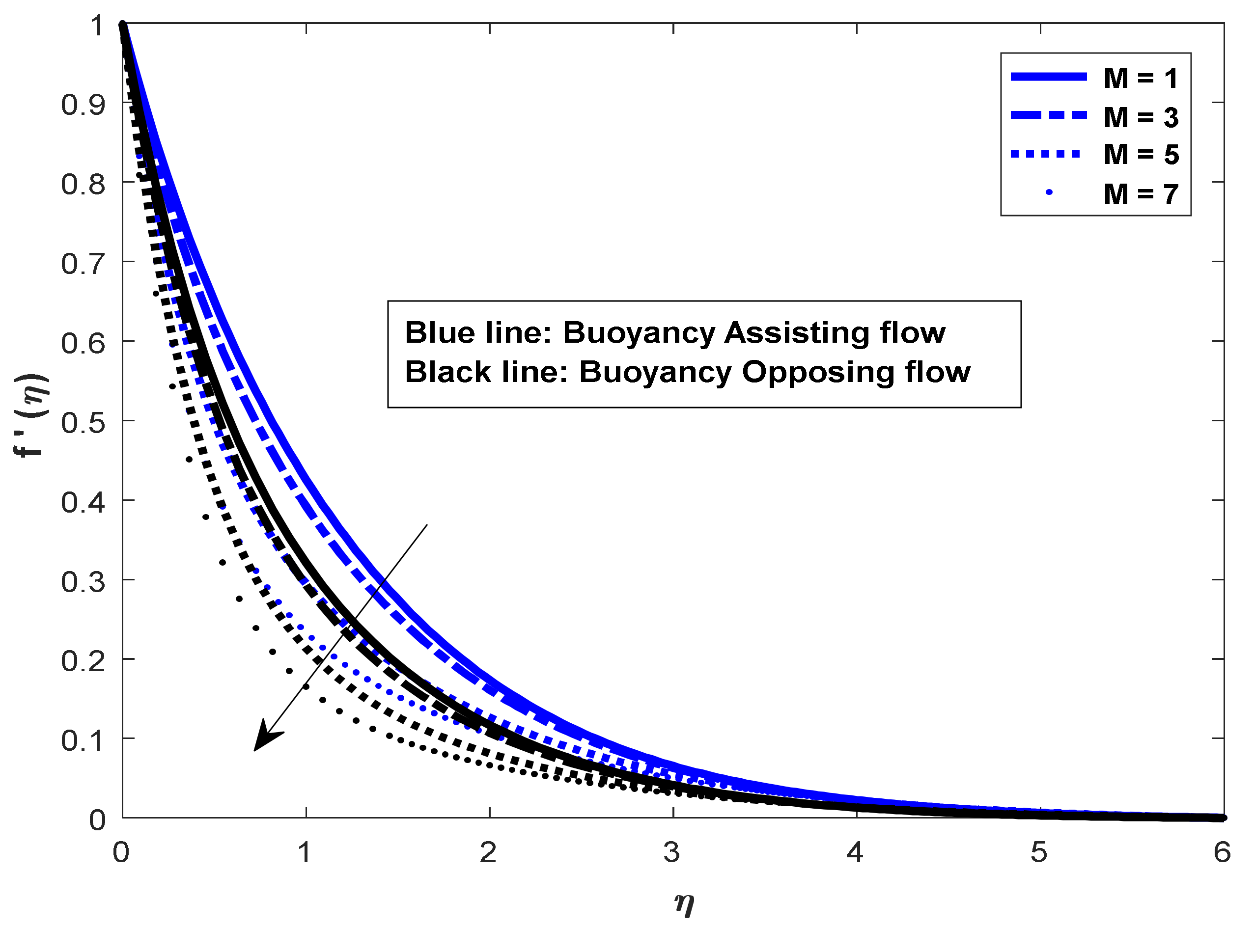
Figure 1. M on velocity.
Mathematics 10 02456 g001
Figure 2. M on temperature.
Mathematics 10 02456 g002
Figure 3. M on salt_1 concentration.
Mathematics 10 02456 g003
Figure 4. M on salt_2 concentration.
Mathematics 10 02456 g004
Figure 5. Pr on velocity.
Mathematics 10 02456 g005
Figure 6. Pr on velocity temperature.
Mathematics 10 02456 g006
Figure 7. Pr on salt_1 concentration.
Mathematics 10 02456 g007
Figure 8. Pr on salt_2 concentration.
Mathematics 10 02456 g008
Figure 9. N c 1 on velocity.
Mathematics 10 02456 g009
Figure 10. N c 1 on temperature.
Mathematics 10 02456 g010
Figure 11. N c 1 on salt_1 concentration.
Mathematics 10 02456 g011
Figure 12. N c 1 on salt_2 concentration.
Mathematics 10 02456 g012
Figure 13. N c 2 on velocity.
Mathematics 10 02456 g013
Figure 14. N c 2 on temperature.
Mathematics 10 02456 g014
Figure 15. N c 2 on salt_1 concentration.
Mathematics 10 02456 g015
Figure 16. N c 2 on salt_2 concentration.
Mathematics 10 02456 g016
Figure 17. L e 2 on velocity.
Mathematics 10 02456 g017
Figure 18. L e 2 on temperature.
Mathematics 10 02456 g018
Figure 19. L e 2 on salt_1 concentration.
Mathematics 10 02456 g019
Figure 20. L e 2 on salt_2 concentration.
Mathematics 10 02456 g020
Figure 21. L e 1 on velocity.
Mathematics 10 02456 g021
Figure 22. L e 1 on temperature.
Mathematics 10 02456 g022
Figure 23. L e 1 on salt_1 concentration.
Mathematics 10 02456 g023
Figure 24. L e 1 on salt_2 concentration.
Mathematics 10 02456 g024
Figure 25. Surface plots of the f 0 for dissimilar values of M .
Mathematics 10 02456 g025
Figure 26. Surface plots of the θ 0 for dissimilar values of M .
Mathematics 10 02456 g026
Figure 27. Surface plots of the ϕ 0 for different values of M .
Mathematics 10 02456 g027
Figure 28. Surface plots for the f 0 for dissimilar values of Pr .
Mathematics 10 02456 g028
Figure 29. Surface plots for the θ 0 for dissimilar values of Pr .
Mathematics 10 02456 g029
Figure 30. Surface plots for the ϕ 0 for dissimilar values of Pr .
Mathematics 10 02456 g030
Figure 31. Surface plots for the f 0 for dissimilar values of N c 1 .
Mathematics 10 02456 g031
Figure 32. Surface plots for the θ 0 for dissimilar values of N c 1 .
Mathematics 10 02456 g032
Figure 33. Surface plots for the ϕ 0 for dissimilar values of N c 1 .
Mathematics 10 02456 g033
Figure 34. Surface plots for the f 0 for dissimilar values of N c 2 .
Mathematics 10 02456 g034
Figure 35. Surface plots for the θ 0 for dissimilar values of N c 2 .
Mathematics 10 02456 g035
Figure 36. Surface plots for the ϕ 0 for dissimilar values of N c 2 .
Mathematics 10 02456 g036
Figure 37. Surface plots for the f 0 for dissimilar values of L e 1 .
Mathematics 10 02456 g037
Figure 38. Surface plots for the θ 0 for dissimilar values of L e 1 .
Mathematics 10 02456 g038
Figure 39. Surface plots for the ϕ 1 0 for dissimilar values of L e 1 .
Mathematics 10 02456 g039
Figure 40. Surface plots for the ϕ 2 0 for dissimilar values of L e 1 .
Mathematics 10 02456 g040
Figure 41. Surface plots for the f 0 for dissimilar values of L e 2 .
Mathematics 10 02456 g041
Figure 42. Surface plots for the θ 0 for dissimilar values of L e 2 .
Mathematics 10 02456 g042
Figure 43. Surface plots for the ϕ 1 0 for dissimilar values of L e 2 .
Mathematics 10 02456 g043
Figure 44. Surface plots for the ϕ 2 0 for dissimilar values of L e 2 .
Mathematics 10 02456 g044
Table 1. Comparison values of Nusselt number θ 0 for various values of Prandtl number when M = λ = N c 1 = N c 2 = L e 1 = L e 2 = 0 .
Pr θ 0
Ferdows et al. [17]Present Results
10.95470.9546
21.47151.4711
31.86911.8672
Publisher’s Note: MDPI stays neutral with regard to jurisdictional claims in published maps and institutional affiliations.