Article

Adaptive Color Image Encryption Scheme Based on Multiple Distinct Chaotic Maps and DNA Computing

1
Department of Electronics and Instrumentation Technology, University of Kashmir, Srinagar 190006, India
2
Department of Data Science, Norwegian University of Life Sciences (NMBU), 1433 Ås, Norway
3
Department of Industrial Economics, Norwegian University of Life Sciences (NMBU), 1433 Ås, Norway
4
Faculty of Computers and Information Technology (FCIT), University of Tabuk, Tabuk 47711, Saudi Arabia
5
Industrial Innovation and Robotic Centre (IIRC), University of Tabuk, Tabuk 47711, Saudi Arabia
6
Visual Analytics for Knowledge Laboratory (VIS2KNOW Lab), Department of Applied Artificial Intelligence, School of Convergence, College of Computing and Informatics, Sungkyunkwan University, Seoul 03063, Korea
*
Authors to whom correspondence should be addressed.
Mathematics 2022, 10(12), 2004; https://doi.org/10.3390/math10122004
Submission received: 7 May 2022 / Revised: 2 June 2022 / Accepted: 7 June 2022 / Published: 10 June 2022
(This article belongs to the Special Issue Chaos-Based Secure Communication and Cryptography)

Abstract

:
In this paper, we propose an adaptive encryption scheme for color images using Multiple Distinct Chaotic Maps (MDCM) and DNA computing. We have chosen three distinct chaotic maps, including a 2D-Henon map, a Tent map, and a Logistic map, to separately encrypt the red, green, and blue channels of the original image. The proposed scheme adaptively modifies the parameters of the maps, utilizing various statistical characteristics such as mean, variance, and median of the image to be encrypted. Thus, whenever there is a change in the plain image, the secret keys also change. This makes the proposed scheme robust against the chosen and known plaintext attacks. DNA encoding has also been used to add another layer of security. The experimental analysis of the proposed scheme shows that the average value of entropy is approximately eight, the Number of Pixels Change Rate (NPCR) and Unified Average Changing Intensity (UACI) are 99.61% and 33%, respectively, and correlation coefficients close to zero, making the scheme not only reliable but also resilient against many attacks. Moreover, the use of low-dimensional maps reduces the computational costs of the scheme to a large extent.

1. Introduction

With the increase in digitization, the need for and importance of information security also increase. To transmit information with ease, security is the ultimate target of digital communication. Nowadays, it has become an important issue to ensure secure communication for the defense department, commercial, and medical fields [1,2]. Digital information is available in various formats such as images, videos, and audio. This information can be accessed on different social and web platforms. One of the most common carriers of digital information is images, and thus, they require significant protection against various attacks that could otherwise reveal crucial information and put the security of the system in danger.
Image encryption is an important and prominent method that ensures the security of images. Numerous standard encryption methods such as International Data Encryption Algorithm (IDEA), Rivest Shamir Adleman (RSA), Advanced Encryption Standard (AES), and Data Encryption Standard (DES) exist, but these are used mainly for encryption of textual data and are not suitable for digital images. The reason is that these standard methods of encryption comprise many rounds and operations. Moreover, there are some inherent features of digital images, such as data redundancy, bulk data capacity, and strongly correlated adjacent pixels, as a result of which the traditional ciphers require high computational costs, thus, making them inappropriate for use in real-time image encryption [3,4,5].
The trend nowadays involves designing encryption algorithms that are based on chaos. The reason for this is that chaos has various fundamental characteristics related to cryptography [6,7,8,9,10,11]. Among various features of chaos, its high sensitivity to the preliminary conditions and control parameters, computational efficiency, and non-periodicity are the important properties that make chaos-based systems a preferable option for creating a physical security system [12,13,14]. Several efficient chaos-based image encryption schemes have been presented [15,16,17,18,19,20,21]. However, some of the schemes are insecure, such as the ones given in [22,23].
In recent years, because of the various striking characteristics of DNA computing, such as massive parallelism, high speed, very large storage capability, and ultra-low power consumption, it is now being used in the field of cryptography. Many researchers are now combining chaos with DNA computing to create further improvement in the security and efficiency of the cryptosystem. Many such algorithms have been proposed in [24,25,26,27,28,29,30,31,32,33,34].
However, some of the reported algorithms, such as [24,25,28,31,33], have certain drawbacks, i.e., they are secret keys plain-image independent, making them vulnerable to chosen and known plain text attacks. In some methods, such as [27,30,31,32], either high-dimensional maps are being used or some transform operations are involved, thus increasing the computational complexity of the schemes in terms of power, time, and other resources. These limitations make the existing systems less suitable for critical information exchange, reducing their adoptability for several security-related applications.
Taking into consideration the above drawbacks, we propose an adaptive encryption scheme for color images with the following original key contributions:
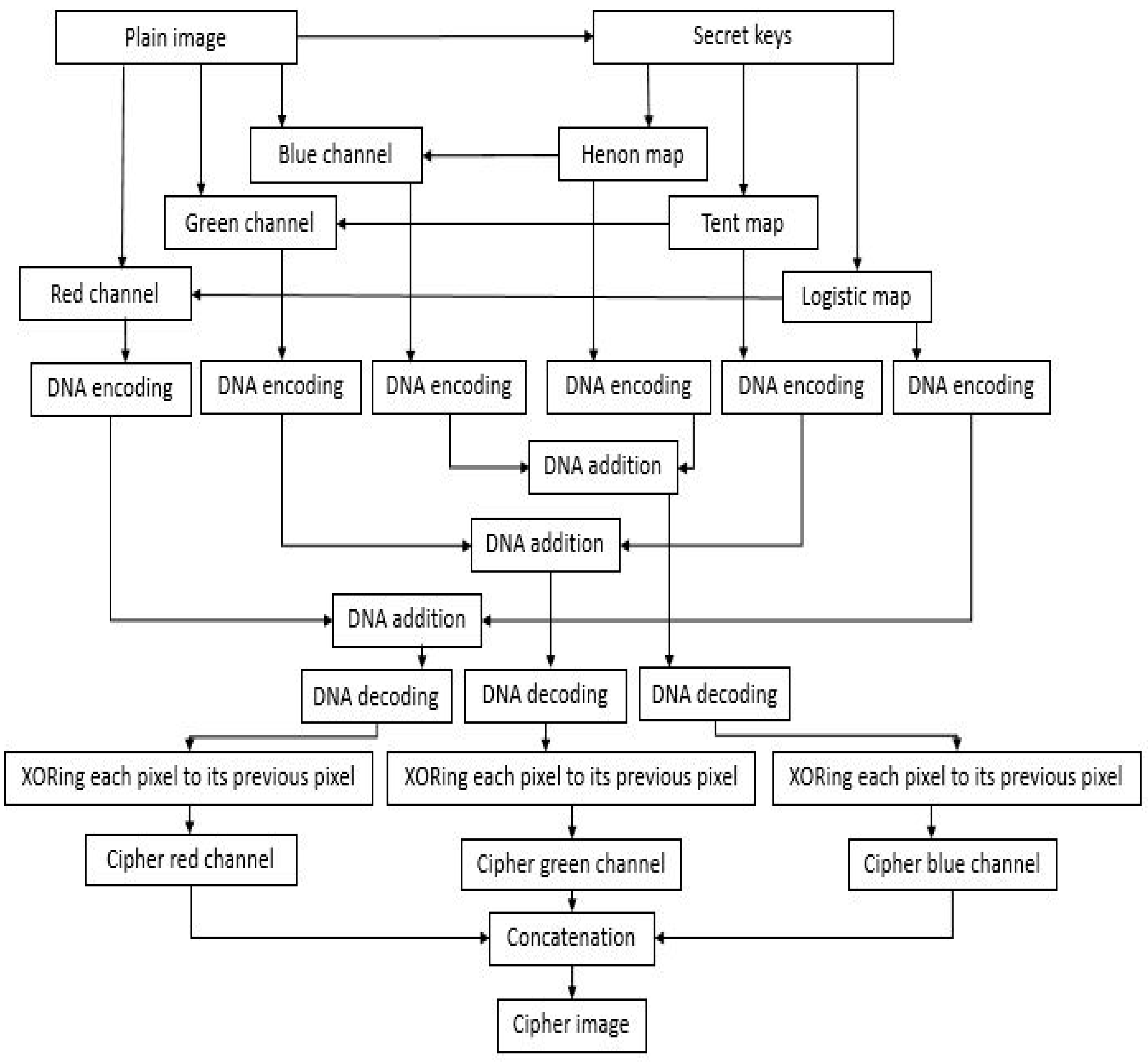
  • The proposed scheme uses a logistic map, a tent map, and a 2D Henon map. Each chaotic map separately encrypts the red channel, green channel, and blue channel, respectively.
  • The use of low-dimensional maps ensures that the proposed algorithm has better computational efficiency. At the same time, the scheme performs better than some recently proposed state-of-the-art image encryption schemes.
  • Adaptive encryption helps to determine various preliminary conditions and control variables of the chaotic maps by making the secret keys plain image dependent. So, every time the plain image is changed, different secret keys will be generated. This makes the scheme robust against the chosen and known plaintext attacks.
  • Further enhancement in the efficiency of the scheme is provided by involving DNA computation in the diffusion phase.
The rest of the paper is structured by presenting the related work in Section 2 and the preliminaries in Section 3. The proposed scheme is introduced in Section 4. The analysis of the scheme is carried out and various results are shown in Section 5. In the end, Section 6 gives the conclusion of this work.

2. Related Work

Numerous image-encryption algorithms based on chaos have been introduced. Khan and Masood [35] presented a chaos-based encryption technique for color images that involves multiple discrete dynamical maps. To carry out diffusion and confusion, the scheme makes use of several 1D and 2D maps. Farah et al. [27] used chaos theory, fractional Fourier transform, and DNA operations to propose an optical image encryption scheme. A DNA matrix was obtained upon the transformation of the plain image by generating random phase masks utilizing the Lorenz map. Then, fractional Fourier transform was implemented thrice on the matrix. Wu et al. [11] proposed a 2D Discrete Wavelet Transform (DWT) and 6D hyperchaotic system-based color image encryption algorithm. Two-dimensional DWT is employed to divide the original image into four image sub-bands and then a keystream is used to permute the sub-bands. Kang and Guo [36] presented a spatiotemporal chaotic system and DNA encoding-based color image encryption technique. Firstly, three DNA matrices are obtained from the plain image based on DNA coding rules. Then, a mixed linear non-linear coupled map lattice (MLNCML) system is used to generate a scrambling matrix that is used to perform permutation on the combined DNA matrix.
Wang et al. [25] presented a Coupled Map Lattice (CML) and DNA sequence operations-based color-image encryption scheme. A matrix is constructed using the three-color plain image components. CML is used to accomplish confusion on the matrix of pixels and the rules of DNA encoding and decoding are applied in the process of permutation. Rehman et al. [26] proposed an encryption algorithm for color images based on the Secure Hash Algorithm (SHA-2) and chaos theory, employing exclusive-OR (XOR) and complementary rules of DNA.
Valandar et al. [37] put forward a three-dimensional chaotic map-based fast encryption scheme for color images. RGB channels are bit-XORed with the three numbers produced by the map. The image is divided into 4 × 4 parts with each part consisting of 16 × 16 blocks, and then different keys of the presented map are used to permute the blocks. Elshamy et al. [38] presented an encryption scheme for color images using chaos. A hybrid encryption technique utilizing three distinct chaos maps: Baker, Arnold, and Henon, each applied to a single channel of Red-Green-Blue is used in the model. Three separate keys are used in unlocking encryptions, thus enhancing information security. Alghafis et al. [39] put forward an efficient color image encryption technique based on chaotic and DNA sequencing. This scheme uses a chaotic system consisting of a logistic map, a Henon map, and a Lorenz system to generate random sequences. In addition, after confusion and diffusion, an operation of DNA fusion is implemented on the DNA image.
Zheng and Liu [40] proposed an encryption algorithm based on an improved 2D logistic sine chaotic map (2D-LSMM). The input of the sine map is controlled using logistic map. DNA coding and operation rules are decided by 2D-LSMM chaotic sequences. Zang et al. [41] introduced a 1D discrete chaotic system. By parameter adjustment, the chaotic system is distributed uniformly. Finally, based on the uniformly distributed discrete chaotic system and DNA encoding, an image encryption algorithm is put forward. Plaintext is used to determine the DNA coding and decoding rules.
Broumandnia [42] presented an image encryption algorithm based on the Galois field in chaotic maps. The algorithm mainly consists of diffusion and permutation. In the diffusion stage, the overlapping rows and columns of the image pixels are mixed by using matrix multiplication operation in GF (256). In the permutation stage, a 2D or 3D chaotic map is used to change the pixel positions. Nardo et al. [43] proposed an image encryption scheme using finite-precision error. Two natural different interval extensions are used to implement a chaotic system to obtain the error. Zhang and Yan [44] proposed an RNA and pixel depth-based adaptive chaotic image encryption algorithm. The secret keys are generated by simultaneously using the hash value of a plain image and the current time to achieve one-image, one-key, and one-time pad. The pixel depth plays an integral role in the entire process of key generation, scrambling, and diffusion.
Among the above-mentioned algorithms, those reported in [25,35,37,38] have shortcomings such as the secret key being independent of the plain image, thereby making the algorithm insecure against chosen and known attacks. Few of them, such as [11,27], involve either high dimensional maps or transform operations as well; thus, the overall computational cost is high and such systems are not suitable for applications, needing a fast response.
The proposed encryption algorithm resolves the above issues by using a tent map, a logistic map, and a Henon map. The logistic map is utilized to encrypt the red channel, the tent map encrypts the green channel, and the Henon map is used to encrypt the blue channel. All the preliminary conditions and controlling parameters of the maps are adaptively modified by mean, variance, and median of the plain image to make the keys plain-image dependent to avoid any known and chosen attacks. At the same time, low-dimensional maps make the overall algorithm computationally less complex. The efficiency and security of the algorithm are further improved using DNA computation.

3. Preliminaries

Chaos is used in the study of dynamic systems. Because of various properties of chaos, such as being highly sensitive to preliminary conditions and other control variables, it has found its use in cryptography. Pseudo-Random Number (PRN) sequences or key streams are generated using chaotic maps. In the proposed scheme, three discrete chaotic maps are utilized to generate the key streams.

3.1. Logistic Map

This is the most commonly used chaotic map and, being one-dimensional, it is among the simplest maps as well. Biologist Robert May first introduced this map in 1976 [45].
Mathematically, it is expressed by Equation (1) given below:
  x ( k ) = μ × x ( k 1 ) × ( 1 x ( k 1 ) )  
where the iteration index is k, µ is the control parameter, and ∈ (0, 4), x(0) is the preliminary condition, and ∈ (0, 1). To exhibit chaotic behavior, µ ∈ (3.5699456, 4).

3.2. Tent Map

The tent map is also a 1D map like the logistic map, and is piecewise chaotic. Equation (2) represents the mathematical expression of the tent map:
x ( n ) = f ( x ( n ) , r ) = r × x ( n 1 ) ,   0 < x ( n 1 ) 0.5 r × ( 1 x ( n 1 ) ) ,   0.5 < x ( n 1 ) 1
Here, the iteration index is n, r ∈ [0, 2] is the control parameter, but to display chaotic behavior, r ∈ [1, 2] or closer to 2. x(n − 1) is the initial condition of the map, and ∈ [0, 1].

3.3. Henon Map

It is a 2D discrete chaotic map and maps a point ( x 0 , y 0 ) to another point. Equations (3) and (4) express the Henon map equations:
                              x n + 1 = 1 a x n + y n            
      y n + 1 = b x n    
where, x 0   and   y 0   are the preliminary conditions, and a and b are the control parameters. To produce chaotic behavior, the usual values of (a, b) (1.4, 0.3).

3.4. DNA Coding

DNA structure comprises double helical strands, which in turn are composed of simpler units called nucleotides [46]. The four bases or nucleotides are Adenine (A), Thymine (T), Guanine (G), and Cytosine (C). Adenine and Thymine are complements of each other. Similarly, Guanine and Cytosine are each other’s complements. In binary numbers, zero and one are complements. Similarly, 00 and 11 and 01 and 10 are also complements. So, if these four DNA bases are used to encode 00, 11, 01, and 11, there will be a total of 24 combinations, out of which only eight coding combinations satisfy Watson–Crick complementary rule. These eight coding rules are given in Table 1.

3.5. DNA Computing

The first experiment on DNA computing was performed by Adleman in 1991, and thus, a new stage in the information era began [47]. Based on the rules of DNA encoding and decoding, certain operations can be carried out on the DNA sequences such as addition, subtraction, XOR, etc., given in Table 2, Table 3 and Table 4, respectively, as per rule 3.

4. Proposed Scheme

In this section, a novel adaptive color image encryption scheme based on MDCM and DNA computation is presented. The block diagram of the proposed encryption scheme is presented in Figure 1, comprising various phases.

4.1. The Encryption Algorithm

The various phases in encryption algorithm are discussed in the following steps:
  • Step 1: In the proposed scheme, the first step is the key generation phase. In this phase, three chaotic maps are used: a tent map, a logistic map, and a Henon map. The preliminary conditions and control variables of all three maps are dynamically controlled using statistical plain image characteristics such as the mean, variance, and median. This makes the secret keys dependent on the plain image so that any change in the image may be reflected in the output as well. In this scheme, a random 8 × 8 plain image pixel block is chosen. The arithmetic means, variance, and median of this pixel block are determined and then normalized. The normalized mean is employed to obtain the starting conditions of the logistic map and tent map and to obtain control variable ‘b’ of the Henon map. Likewise, the use of normalized variance is made to obtain the control parameters of the logistic map and tent map, and control variable ‘a’ of the Henon map. The two starting conditions of the Henon map are obtained using the normalized median of the block.
  • Step 2: In this step, the permutation process is carried out. Permutation involves changing the pixel positions to reduce the correlation among the neighboring pixels in the plain image. The original color image with size M × N × 3 is initially taken as the input and then split into red, green, and blue channels, each reshaped to a size of M × N × 1 . The preliminary condition and control parameter values are given to the logistic map and it is iterated M × N times to generate a PRN sequence, which is then employed to permute the red channel of the image. Similarly, on giving the values of the preliminary condition and control variable, the tent map is iterated M × N times and a PRN sequence is generated. This sequence is used in scrambling the green channel of the image. Finally, the Henon map is iterated M × N times to generate two PRN sequences. One of these sequences is used in the permutation of the blue channel of the image. So, in the permutation phase, three permuted images are obtained.
  • Step 3: This step involves the DNA-encoding phase. In this phase, the three permuted images obtained are encoded into three DNA sequences D N A s e q 1 , D N A s e q 2 , and D N A s e q 3 according to a DNA-encoding rule, each with a size of 4 × M × N . In the proposed algorithm, the encoding is performed as per DNA rule 3. After giving different values of preliminary conditions and control variables, the logistic and tent map are iterated again M × N times to generate two new PRN sequences. These two sequences, along with the other sequence from the Henon map, are also encoded into DNA sequences as per the same rule 3 to get three more DNA sequences: D N A s e q 4 , D N A s e q 5 ,   and   D N A s e q 6 , respectively.
  • Step 4: This step involves the substitution process of the suggested algorithm. In any encryption algorithm, substitution is of great significance and is incorporated in changing or modifying the pixel values. In this phase, DNA computation is carried out on the six DNA sequences obtained so far. The D N A s e q 1 is added with the D N A s e q 4 as per DNA addition rule 3. Likewise, the D N A s e q 2 is added with the D N A s e q 5 and finally D N A s e q 3   is added with D N A s e q 6   as per the same rule 3. Thus, at the end of the substitution phase, we get three DNA sequences.
  • Step 5: This step involves the DNA decoding process. In this phase, each of the three DNA sequences obtained in the substitution phase is decoded into a binary stream according to the DNA decoding rule 3 and then the binary stream is converted into decimal form. After reshaping the decimal sequence, each element is XORed with the elements preceding that index in the sequence to finally get the three ciphered channels. The concatenation of these channels gives the final encrypted image.

4.2. The Decryption Algorithm

The algorithm for decryption is similar to that of the encryption and involves the same steps in reverse. After decrypting all three channels, they are concatenated to give the final decrypted image.

5. Experimental Results and Security Analysis

In this section, experimental results of the suggested scheme are presented, and performance analysis is carried out. The analysis is given in terms of key sensitivity, keyspace, various statistical parameters such as histogram, information entropy, correlation coefficients, differential attack analysis, etc. In the proposed algorithm, various standard RGB images were used as plain images. Figure 2 shows Lena of 256 × 256 × 3 as the plain image and its three channels red, green, and blue after decomposition, along with their corresponding encrypted and decrypted versions as well.
Various other standard RGB images and their encrypted and decrypted versions are displayed in Figure 3.

5.1. Keyspace Analysis

Keyspace means all the digital space that can be employed as the encryption/decryption key. For an effective encryption scheme, its value should be as large as possible, at least equal to 2 100 (≈ 10 30 ), to withstand the brute-force attacks [1]. The presented scheme makes use of three chaotic maps. There are two parameters: one initial condition and one control parameter in both the logistic map and tent map. Both maps are used twice in the algorithm, making a total of eight parameters or keys. Additionally, a 2D-Henon map is used once. It has four parameters: two control variables and two preliminary conditions. If each key has precision up to 10 10 ,   the keyspace is ( 10 10 ) 12 = ( 10 ) 120   ( = 2 400 ) . Additionally, one rule is used out of eight DNA-encoding rules and the encoding process is carried out six times. Likewise, the DNA addition and decoding operations are also performed thrice each; therefore, the total keyspace of the proposed algorithm = ( 2 400 ) × ( 2 3 ) 12 =   2 436 , which is much larger than the required value; thus, this scheme could very well resist the attacks of brute force.

5.2. Key Sensitivity Analysis

There should be an extreme sensitivity in a cryptosystem concerning even the slightest change in any of the keys used. For this, key-sensitivity analysis is performed by first encrypting the image using a set of right keys and then decrypting it after bringing a very minute change in one of the keys used in the algorithm. Under such a scenario, the decrypted image should not reveal any sort of information about the plain image, depicting the high sensitivity of the algorithm to the keys, and should withstand any such attack from the adversary. To test the sensitivity of the suggested algorithm to the secret key, image Lena is firstly encrypted by a set of correct keys and then decrypted by insignificantly changing one of the keys. Here, the value of the normalized variance used in obtaining the various parameters or secret keys is changed by 10 10 .  Figure 4 shows the key-sensitivity analysis of the scheme.
Figure 4d clearly shows that the proposed algorithm is extremely sensitive to the secret keys after changing the value of one of the keys, i.e., increasing the normalized variance by 10 10 .

5.3. Statistical Attack Analysis

This section analyzes various statistical attacks carried out on the proposed system. The results in terms of histogram analysis, entropy analysis, and fidelity analysis are discussed as follows.

5.3.1. Histogram Analysis

A histogram represents the occurrences of pixels in digital images. It should be quite uniform after an encryption algorithm is applied to an image to deceive the attacker. The uniformity of encrypted images is one aspect to conceal the actual information of digital images. Figure 5 shows the histogram analysis of image Lena. One can quite obviously observe that the histogram of RGB channels after encryption is very much uniform, and thus, the information about plain image remains hidden.

5.3.2. Information Entropy Analysis

The haphazardness in the plain image information content is determined by information entropy. For an eight-bit image, its ideal value is eight. It is represented using the expression given in Equation (5).
    H ( S ) = i = 0 2 N 1 P ( S i ) × l o g ( 1 / P ( S i ) )  
where N is the bit length of the value of a pixel and P ( S i ) gives the probability of symbol S i . The entropy of some standard RGB images obtained using the proposed algorithm is given in Table 5. The results are also compared with other schemes, and it is visible that the results are better in the proposed scheme, being near enough to the ideal value of eight. So, there is a very low probability of information leakage making these images resistant against statistical attacks.

5.3.3. Correlation Coefficient Analysis

There is a very high correlation, which also means a large similarity between the adjacent plain image pixels along with different directions. In a digital image, its value lies in the range of −1 and 1. One aspect of an encryption scheme is to break this correlation among the adjacent pixels and bring its value closer to zero. Such a scheme is said to be a cryptographically secure one. Mathematically, it can be defined as Equation (6):
          r x y = c o v ( x , y ) / V ( x ) × V ( y )    
where, c o v ( x , y ) = 1 / N i = 1 N ( x i E ( x ) ) × ( y i E ( y ) )
V ( x ) = 1 / N i = 1 N ( x i E ( x ) ) 2
( x ) = 1 / N i = 1 N ( x i )  
where the number of adjacent pixel pairs is given by N, the adjacent pixel pair has gray values of x and y, E(x) denotes the mean, the variance is denoted by V(x), and covariance by C o v ( x , y ) . Table 6 displays values of correlation coefficients of different encrypted images along with horizontal (CHR, CHG, CHB), vertical (CVR, CVG, CVB), and diagonal (CDR, CDG, CDB) directions. The values are closer to zero, indicating the encrypted images to be uncorrelated, which also suggests that the suggested scheme is secure enough against statistical attacks.

5.4. Peak Signal to Noise Ratio (PSNR)

PSNR is an attribute that helps to check the quality of an image-encryption technique. It measures and indicates the changes in the value of plain-image pixels and that of encrypted images. For a secure encryption technique, its value should be low enough, from seven to nine. PSNR can be expressed mathematically by Equation (7).
PSNR = 10 × l o g ( P ) 2 / M S E  
where P denotes the peak pixel intensity for an eight-bit image, MSE denotes the mean square error and is given in Equation (8).
M S E = 1 M × N i 1 M j = 1 N ( O ( i , j ) E ( i , j ) ) 2  
where O is the original image and E is the encrypted image.

5.5. Structural Similarity (SSIM)

SSIM measures the similarity between the plain image and the encrypted image. It indicates the amount of structural information modified in the plain image. Its value should be low enough, closer to 0. SSIM can be calculated using Equation (9).
  SSIM ( o , e ) = ( 2 μ o μ e + C 1 ) ( 2 σ o e + C 2 ) ( μ o 2 μ e 2 + C 1 ) ( σ o 2 σ e 2 + C 2 )                            
where μ o = mean of the original image, μ e = mean of the encrypted image, σ o 2 = original image variance, σ e 2 = encrypted image variance, and σ o e = covariance between original and encrypted images. C 1 = ( h 1 L ) 2 , C 2 = ( h 2 L ) 2 , L = 255, h 1 = 0.01 and h 2 = 0.03.
Table 7 gives the SSIM and PSNR values for various RGB images obtained using the presented scheme. Both SSIM and PSNR values are low enough to suggest that there is very little similarity between the plain and the encrypted image and high noise between the two images, respectively.

5.6. Differential Attack Analysis

An algorithm for encryption of images should be such that even if a slight change occurs in the plain image, its cipher image should also change, i.e., the sensitivity of the algorithm concerning the plain image should be high. This property makes an algorithm robust against differential attacks. In such attacks, the adversary slightly changes a plain image. He then encrypts the image before and post the change, and then analyzes the distribution of these images to determine any kind of statistical pattern. Two parameters are employed to determine resistance against such attacks: Number of Pixels Changing Rate (NPCR) and Unified Average Changing Intensity (UACI).
The absolute pixels whose value varies in differential attacks is given by NPCR, whereas the focus of UACI is on the averaged difference between the two encrypted images. NPCR and UACI can be determined using Equations (10) and (11), respectively.
  NPCR ( C 1 , C 2 ) = 1 M N i = 1 M j = 1 N D ( i , j ) × 100 %
  UACI ( C 1 , C 2 ) = 1 M N i = 1 M j = 1 N | C 1 ( i , j ) C 2 ( i , j ) | 255 × 100 %    
  D ( i , j ) = { 0 ,   i f   C 1 ( i , j ) = C 2 ( i , j ) 1 , i f   C 1 ( i , j ) C 2 ( i , j )        
where the dimensions of the original image are given by M and N. Cipher images before and post the change in the value of the pixel at location ( i , j ) are given by C 1 ( i , j )   and C 2 ( i , j ) , respectively. Ideally, the respective NPCR and UACI values should be equal to 99.61% and 33.46%, [48]. In the proposed scheme, various RGB images are taken, and one-bit change is introduced in the plain images. UACI and NPCR are evaluated, and their values are given in Table 8 along with a comparison to other schemes.
The results obtained from the proposed scheme outperform the results of those compared with it and are found to be close to their ideal values. It implies that the presented scheme is extremely sensitive to the plain image and can resist the differential attacks very well.

5.7. Robustness Analysis

It is inevitable in real-world applications that some noise gets added to the information or it suffers some losses during transmission over a communication channel. Robustness is the ability of an encryption algorithm to recover the original image from a cropped or noisy cipher image.

5.7.1. Noise Attack Analysis

To check the robustness of the proposed scheme against noise attacks, we added salt and pepper noise of different densities to the encrypted image of Lena, as shown in Figure 6. The noise densities used are 0.01, 0.05, and 0.1 in Figure 6a–c, respectively. The corresponding decrypted images are shown in Figure 6d–f. It is evident from the figure that despite the cipher images being noisy, the corresponding decrypted images are still perceivable. This shows the robustness of the proposed scheme.

5.7.2. Cropping Attack Analysis

In order to test the robustness of the proposed scheme against cropping attack, we used different cropping levels such as 1/8, 1/4, and 1/2, as depicted in Figure 7a–c, respectively. We find out in Figure 7d–f that the corresponding decrypted images can still be recognized. Thus, the proposed algorithm also succeeds in resisting the cropping attack.
One of the most important indexes to measure the quality of encryption is PSNR. A low PSNR value signifies good encryption quality, and a high value signifies better perceptual security. We evaluate the robustness of the proposed algorithm against salt-and-pepper-noise attack and cropping attack in terms of PSNR and MSE, defined in Equations (7) and (8), respectively. The results obtained for the image Lena are presented in Table 9 (noise attack analysis) and Table 10 (cropping attack analysis).
From Table 9 and Table 10, it is observed that both PSNR and MSE have good values, which indicate that the proposed scheme has good perceptual security and is robust against noise and cropping attacks.

5.8. Computational Complexity Analysis

The chaotic sequence generation, permutation operations, and diffusion operations in any chaos-based image encryption algorithm constitute its computational costs. The computational complexity is described by the number of times each operation is repeated in various stages based on plain image pixels M × N.
The key generation phase in the proposed algorithm involves generating the sequences using a logistic map, a tent map, and a Henon map, with each sequence equal to the number of image pixels. Both the logistic map and tent map are iterated twice to generate two sequences and the Henon map is iterated only once. So, the complexity is O(5 × M × N).
Table 11 shows the number of times various other operations are repeated in the proposed algorithm.
On aggregating the complexities of all these operations, the total computational complexity of the proposed scheme is O(59 × M × N), which is much less than the complexity of other state-of-the-art schemes given in Table 12.
Table 12 shows that the proposed scheme is computationally efficient compared to other related schemes.

5.9. Speed Analysis

The swiftness of an algorithm is a critical feature of a good cryptosystem. Speed analysis of the suggested algorithm is carried out by measuring the encryption/decryption time for various standard color images. The scheme implementation was performed using MATLAB 2019a (version 9.6, Mathworks, Natick, MA, USA) on the operating system Windows 10 with processor Intel® core™ i7-8565U CPU @ 1.8GHZ and 8GB RAM. The speed analysis of the suggested scheme is given in Table 13.

6. Conclusions

Recently, chaotic systems have found their application in various fields such as cryptography and digital communication. In this paper, an adaptive color-image encryption scheme based on MDCM and DNA computing is presented. In the proposed scheme, three chaotic maps are used to perform encryption of the three channels separately. A logistic map encrypts the red channel, a Tent map encrypts the green channel, and a 2D-Henon map is used to encrypt the blue channel. We have tried other scenarios as well, wherein these maps are exchanged with each other to encrypt the different channels. However, in every such situation, the values of various parameters for performance evaluation start degrading. We only get optimal values of these parameters by adopting the proposed encryption method. The use of low-dimensional maps to encrypt the images makes the scheme computationally less complex. The preliminary conditions and control variables of all these maps are controlled using statistical plain-image characteristics such as mean, variance, and median, making the secret keys plain-image dependent, and thus the scheme is robust against chosen and known plaintext attacks. In the diffusion phase, DNA addition operation followed by XOR operation is carried out to obtain the encrypted channels that, upon concatenating, give the final encrypted image. Various experimental results are obtained and are found to be closer to their ideal values. NPCR and UACI values come out to be more than 99.61% and 33%, respectively. Correlation coefficient values are approaching zero and the entropy value is approximately equal to the ideal value of eight. Thus, the experimental analysis shows that the suggested scheme is secure enough against many attacks such as statistical attacks and differential attacks. The proposed scheme also shows extreme sensitivity to the keys and has a huge keyspace that makes it secure against brute-force attacks. It also gives a good structural similarity index, making it safe and reliable for image encryption.

Author Contributions

Conceptualization, S.M.; Data curation, P.S.; Formal analysis, S.M. and P.S.; Funding acquisition, S.A.P. and H.U.; Investigation, M.H. and K.M.; Project administration, S.A.P. and K.M.; Supervision, H.U.; Validation, K.M.; Writing—original draft, S.M.; Writing—review & editing, P.S., S.A.P., H.U., M.H. and K.M. All authors have read and agreed to the published version of the manuscript.

Funding

This research was funded by JK Science Technology & Innovation Council, Department of Science and Technology, Government of Jammu and Kashmir, under grant number JKST&IC/SRE/874-77.

Institutional Review Board Statement

Not applicable.

Informed Consent Statement

Not applicable.

Conflicts of Interest

The authors report that there are no competing interest to declare.

References

  1. Alvarez, G.; Li, S. Some basic cryptographic requirements for chaos-based cryptosystems. Int. J. Bifurc. Chaos 2006, 16, 2129–2151. [Google Scholar] [CrossRef] [Green Version]
  2. Liu, H.; Kadir, A.; Niu, Y. Chaos-based color image block encryption scheme using S-box. AEU Int. J. Electron. Commun. 2014, 68, 676–686. [Google Scholar] [CrossRef]
  3. Feynman, R.; Vernon, F., Jr. The theory of a general quantum system interacting with a linear dissipative system. Ann. Phys. 1963, 24, 118–173. [Google Scholar] [CrossRef] [Green Version]
  4. Zhou, Y.; Bao, L.; Chen, C.L.P. A new 1d chaotic system for image encryption. Signal Process 2014, 97, 172–182. [Google Scholar] [CrossRef]
  5. Toughi, S.; Fathi, M.H.; Sekhavat, Y.A. An image encryption scheme based on elliptic curve pseudo-random and advanced encryption system. Signal Process 2017, 141, 217–227. [Google Scholar] [CrossRef]
  6. Ahmad, M.; Ahmad, T. Securing multimedia color imagery using multiple high dimensional chaos-based hybrid keys. Int. J. Commun. Netw. Distrib. Syst. 2014, 12, 113–128. [Google Scholar]
  7. Wu, X.; Li, Y.; Kurths, J. A new color image encryption scheme using CML and a fractional-order chaotic system. PLoS ONE 2015, 10, e0119660. [Google Scholar] [CrossRef] [Green Version]
  8. Liu, H.; Wang, X. Color image encryption using spatial bit-level permutation and high-dimension chaotic system. Opt. Commun. 2011, 284, 3895–3903. [Google Scholar] [CrossRef]
  9. Zhang, W.; Wong, K.W.; Yu, H.; Zhu, Z.L. A Symmetric color image encryption algorithm using the intrinsic features of bit distributions. Commun. Nonlinear Sci. Numer. Simul. 2013, 18, 584–600. [Google Scholar] [CrossRef]
  10. Celik, K.; Kurt, E. A new image encryption algorithm based on the Lorenz system. In Proceedings of the IEEE 8th International Conference on Electronics, Computers and Artificial Intelligence (ECAI), Ploiesti, Romania, 30 June–2 July 2016; pp. 1–6. [Google Scholar]
  11. Wu, X.J.; Wang, D.W.; Kurths, J.; Kan, H.B. A novel lossless color image encryption scheme using 2D DWT and 6D hyperchaotic system. Inf. Sci. 2016, 349–350, 137–153. [Google Scholar] [CrossRef]
  12. Bhat, G.M.; Mustafa, M.; Parah, S.A.; Ahmad, J. Field programmable gate array (FPGA) implementation of novel complex PN-code-generator-based data scrambler and descrambler. Maejo Int. J. Sci. Technol. 2010, 4, 125–135. [Google Scholar]
  13. Parah, S.A.; Ahad, F.; Sheikh, J.A.; Bhat, G.M. On the realization of robust watermarking system for medical images. In Proceedings of the 2015 Annual IEEE India Conference (INDICON), New Delhi, India, 17–20 December 2015; pp. 1–5. [Google Scholar] [CrossRef]
  14. Bhat, G.M.; Mustafa, M.; Ahmad, S.; Ahmad, J. VHDL modeling and simulation of data scrambler and descrambler for secure data communication. Indian J. Sci. Technol. 2009, 2, 41–43. [Google Scholar] [CrossRef]
  15. Huang, H. Novel scheme for image encryption combining 2D logistic-Sine-Cosine map and double random-phase encoding. IEEE Access 2019, 7, 177988–177996. [Google Scholar] [CrossRef]
  16. Nkandeu, Y.P.K.; Tiedeu, A. An image encryption algorithm based on substitution technique and chaos mixing. Multimed. Tools Appl. 2019, 78, 10013–10034. [Google Scholar] [CrossRef]
  17. Cheng, G.F.; Wang, C.H.; Chen, H. A Novel Color Image Encryption Algorithm Based on Hyperchaotic System and Permutation-Diffusion Architecture. Int. J. Bifurc. Chaos 2019, 29, 1950115. [Google Scholar] [CrossRef]
  18. Liu, L.; Miao, S. A new simple one-dimensional chaotic map and its application for image encryption. Multimed. Tools Appl. 2018, 77, 21445–21462. [Google Scholar] [CrossRef]
  19. Parsa, S.; Shabir, P.; Bhat, G.M.; Khan, M. A Security Management Framework for Big Data in Smart Healthcare. Big Data Res. 2021, 25, 100225. [Google Scholar] [CrossRef]
  20. Xiang, H.; Liu, L. An improved digital logistic map and its application in image encryption. Multimed. Tools Appl. 2020, 79, 30329–30355. [Google Scholar] [CrossRef]
  21. Zhang, S.J.; Liu, L.; Xiang, H.Y. A Novel Plain-Text Related Image Encryption Algorithm Based on LB Compound Chaotic Map. Mathematics 2021, 9, 2778. [Google Scholar] [CrossRef]
  22. Li, C.; Xie, T.; Liu, Q.; Cheng, G. Cryptanalyzing image encryption using a chaotic logistic map. Nonlinear Dyn. 2014, 78, 1545–1551. [Google Scholar] [CrossRef] [Green Version]
  23. Zeng, L.; Liu, R.; Zhang, L.Y.; Liu, Y.; Wong, K.W. Cryptanalyzing an image encryption algorithm based on scrambling and Veginère cipher. Multimed. Tools Appl. 2016, 75, 5439–5453. [Google Scholar] [CrossRef] [Green Version]
  24. Liu, L.; Zhang, Q.; Wei, X. A RGB image encryption algorithm based on DNA encoding and chaos map. Comput. Electr. Eng. 2012, 38, 1240–1248. [Google Scholar] [CrossRef] [Green Version]
  25. Wang, X.Y.; Zhang, H.L.; Bao, X.M. Color image encryption scheme using CML and DNA sequence operations. BioSystems 2016, 144, 18–26. [Google Scholar] [CrossRef] [PubMed]
  26. Rehman, A.; Liao, X.; Ashraf, R.; Ullah, S.; Wang, H. A color image encryption technique using exclusive-OR with DNA complementary rules based on chaos theory and SHA-2. Optik 2018, 159, 348–367. [Google Scholar] [CrossRef]
  27. Farah, M.A.B.; Guesmi, R.; Kachouri, A.; Samet, M. A novel chaos-based optical image encryption using fractional Fourier transform and DNA sequence operation. Opt. Laser Technol. 2020, 121, 105777. [Google Scholar] [CrossRef]
  28. Mondal, B.; Mandal, T. A lightweight secure image encryption scheme based on chaos and DNA computing. J. King Saud Univ. Comput. Inf. Sci. 2017, 29, 499–504. [Google Scholar] [CrossRef] [Green Version]
  29. Wu, J.; Liao, X.; Yang, B. Image Encryption Using 2D Henon-Sine Map and DNA Approach. Signal Process. 2018, 153, 11–23. [Google Scholar] [CrossRef]
  30. Zefreh, E.Z. An image encryption scheme based on a hybrid model of DNA computing, chaotic systems, and hash functions. Multimed. Tools Appl. 2020, 79, 24993–25022. [Google Scholar] [CrossRef]
  31. Zhan, K.; Wei, D.; Shi, J.; Yu, J. Cross-utilizing hyperchaotic and DNA sequences for image encryption. J. Electron. Imaging 2017, 26, 013021. [Google Scholar] [CrossRef]
  32. Liu, Z.T.; Wu, C.X.; Wang, J.; Hu, Y.H. A Color Image Encryption Using Dynamic DNA and 4-D Memristive Hyper-Chaos. IEEE Access 2019, 7, 78367–78378. [Google Scholar] [CrossRef]
  33. Liu, Q.; Liu, L.F. Color Image Encryption Algorithm Based on DNA Coding and Double Chaos System. IEEE Access 2020, 8, 83596–83610. [Google Scholar] [CrossRef]
  34. Elmanfaloty, R.A.; Alnajim, A.M.; Abou-Bakr, E. A finite precision implementation of an image encryption scheme based on DNA encoding and binarized chaotic cores. IEEE Access 2021, 9, 136905–136916. [Google Scholar] [CrossRef]
  35. Khan, M.; Masood, F. A novel chaotic image encryption technique based on multiple discrete dynamical maps. Multimed. Tools Appl. 2019, 78, 26203–26222. [Google Scholar] [CrossRef]
  36. Xuejing, K.; Zihui, G. A new color image encryption scheme based on DNA encoding and spatiotemporal chaotic system. Signal Process. Image Commun. 2020, 80, 115670. [Google Scholar] [CrossRef]
  37. Valandar, M.Y.; Barani, M.J.; Ayubi, P. A fast color image encryption technique based on the three-dimensional chaotic map. Opt. Int. J. Light Electron. Opt. 2019, 193, 162921. [Google Scholar] [CrossRef]
  38. Elshamy, A.M.; Hussein, A.I.; Hamed, H.F.A.; Abdelghany, M.A.; Kelash, H.M. Color Image Encryption Technique Based on Chaos. Procedia Comput. Sci. 2019, 163, 49–53. [Google Scholar] [CrossRef]
  39. Alghafis, A.; Firdousia, F.; Khan, M.; Batoola, S.I.; Amin, M. An efficient image encryption scheme based on chaotic and Deoxyribonucleic acid sequencing. Math. Comput. Simul. 2020, 177, 441–466. [Google Scholar] [CrossRef]
  40. Zheng, J.; Liu, L. Novel image encryption by combining dynamic DNA sequence encryption and the improved 2D logistic sine map. IET Image Process. 2020, 14, 2310–2320. [Google Scholar] [CrossRef]
  41. Zang, H.; Tai, M.; Wei, X. Image encryption schemes based on a class of uniformly distributed chaotic systems. Mathematics 2022, 10, 1027. [Google Scholar] [CrossRef]
  42. Broumandnia, A. Image encryption algorithm based on finite fields in chaotic maps. J. Inf. Secur. Appl. 2020, 54, 102553. [Google Scholar] [CrossRef]
  43. Nardo, L.G.; Nepomuceno, E.G.; Arias-Garcia, J.; Butusov, D.N. Image encryption using finite precision error. Chaos Solitons Fractals 2019, 123, 69–78. [Google Scholar] [CrossRef]
  44. Zhang, X.; Yan, X. Adaptive chaotic image encryption algorithm based on RNA and pixel depth. Electronics 2021, 10, 1770. [Google Scholar] [CrossRef]
  45. May, R.M. Simple mathematical models with very complicated dynamics. In The Theory of Chaotic Attractors; Springer: New York, NY, USA, 2004; pp. 85–93. [Google Scholar]
  46. Adleman, L.M. Molecular computation of solutions to combinatorial problems. Science 1994, 266, 1021–1024. [Google Scholar] [CrossRef] [PubMed] [Green Version]
  47. Roberts, K.; Alberts, B.; Johnson, A.; Walter, P.; Hunt, T. Molecular Biology of the Cell; Garland Science: New York, NY, USA, 2002. [Google Scholar]
  48. Ping, P.; Fan, J.; Mao, Y.; Xu, F.; Gao, J. A chaos-based image encryption scheme using digit-level permutation and block diffusion. IEEE Access 2018, 6, 67581–67593. [Google Scholar] [CrossRef]
  49. Samiullah, M.; Aslam, W.; Nazir, H.; Lali, M.I.; Shahzad, B.; Mufti, M.R.; Afzal, H. An image encryption scheme based on DNA computing and multiple chaotic systems. IEEE Access 2020, 8, 25650–25663. [Google Scholar] [CrossRef]
  50. Wu, X.; Kurths, L.; Kan, H. A robust and lossless DNA encryption scheme for color images. Multimed. Tools Appl. 2018, 77, 12349–12376. [Google Scholar] [CrossRef]
  51. Belazi, A.; Talha, M.; Kharbech, S.; Xiang, W. Novel medical image encryption scheme based on chaos and DNA encoding. IEEE Access 2019, 7, 36667–36681. [Google Scholar] [CrossRef]
  52. Sun, S. A novel hyperchaotic image encryption scheme based on DNA encoding, pixel-level scrambling and bit-level scrambling. IEEE Photon. J. 2018, 10, 1–14. [Google Scholar] [CrossRef]
Figure 1. Block diagram of the proposed encryption scheme.
Mathematics 10 02004 g001
Figure 2. (ad) Standard plain RGB Lena image along with the three separate channels, (a1d1) corresponding encrypted images; (a2d2) corresponding decrypted images.
Mathematics 10 02004 g002
Figure 3. Some more standard RGB plain images along with their encrypted and decrypted versions; (a) Peppers (256 × 256 × 3); (b) encrypted peppers; (c) decrypted peppers; (a1) baboon (256 × 256 × 3); (b1) encrypted baboon; (c1) decrypted baboon; (a2) peppers (512 × 512 × 3); (b2) encrypted peppers; (c2) decrypted peppers.
Mathematics 10 02004 g003aMathematics 10 02004 g003b
Figure 4. Key sensitivity analysis of Lena (256 × 256 × 3). (a) Plain RGB Lena; (b) encrypted Lena using a set of keys; (c) decrypted Lena using a correct set of keys; (d) decrypted Lena by bringing a minor change in one of the keys.
Mathematics 10 02004 g004
Figure 5. Histogram analysis of Lena (256 × 256 × 3). (ac) shows the histogram of plain RGB channels and (df) shows the histogram of encrypted RGB channels.
Mathematics 10 02004 g005aMathematics 10 02004 g005b
Figure 6. Noise attack analysis. (ac) Noisy cipher images; (df) corresponding decrypted images.
Mathematics 10 02004 g006
Figure 7. Cropping attack analysis. (ac) Cropped cipher images; (df) corresponding decrypted images.
Mathematics 10 02004 g007
Table 1. Eight kinds of DNA map rules.
12345678
A0000010110101111
T1111101001010000
G0110001100110110
C1001110011001001
Table 2. Rule 3 for DNA addition.
+ATGC
ATCAG
TCGTA
GATGC
CGACT
Table 3. Rule 3 for DNA subtraction.
ATGC
AGCAT
TAGTC
GCTGA
CTACG
Table 4. Rule 3 for DNA XOR.
ATGC
AGCAT
TCGTA
GATGC
CTACG
Table 5. Information entropy analysis.
ImagesProposed[33][35][39]
Entropy Value, H(S)%Age =
H(S)/8 × 100
Entropy Value, H(S)%Age =
H(S)/8 × 100
Entropy Value, H(S)%Age =
H(S)/8 × 100
Entropy Value, H(S)%Age =
H(S)/8 × 100
Lena
(256 × 256 × 3)
R = 7.997399.966R = 7.989299.865R = 7.997399.966R = 7.997699.970
G = 7.997299.965G = 7.990299.877G = 7.997299.965G = 7.997599.968
B = 7.997499.967B = 7.989699.870B = 7.997599.968B = 7.997499.967
Baboon
(256 × 256 × 3)
R = 7.997299.965--R = 7.997299.965R = 7.997299.965
G = 7.997099.962G = 7.997099.962G = 7.997299.965
B = 7.997399.966B = 7.997799.971B = 7.997299.965
Peppers
(256 × 256 × 3)
R = 7.997499.967----R = 7.996799.958
G = 7.997199.963G = 7.997099.962
B = 7.997299.965B = 7.997399.966
Peppers
(256 × 256 × 3)
R = 7.999299.990--R = 7.999399.991--
G = 7.999399.991G = 7.999299.990
B = 7.999299.990B = 7.999399.991
Table 6. Correlation coefficient analysis.
ImagesProposed[35][39]
Lena
(256 × 256 × 3)
CHR = 0.0018CHR = 0.0017CHR = 0.0003
CHG = −0.0032CHG = 0.0011CHG = 0.001
CHB = 0.0022CHB = −0.0030CHB = −0.0009
CVR = 0.0028CVR = −0.0004CVR = 0.003
CVG = 0.0286CVG = 0.0076CVG = −0.004
CVB = 0.1074CVB = 0.0050CVB = −0.0008
CDR = 0.0016CDR = 0.0049CDR = 0.0008
CDG = 0.0022CDG = −0.0002CDG = 0.002
CDB = −0.00075CDB = 0.0049CDB = 0.002
Baboon
(256 × 256 × 3)
CHR = −0.0037CHR = −0.0007CHR = 0.0005
CHG = 0.0010CHG = 0.0057CHG = −0.00003
CHB = 0.0091CHB = 0.0056CHB = 0.005
CVR = −0.1196CVR = 0.0023CVR = 0.002
CVG = −0.0889CVG = 0.0043CVG = 0.005
CVB = 0.0313CVB = 0.0002CVB = 0.0009
CDR = −0.0043CDR = −0.0077CDR = 0.006
CDG = 0.00059CDG = −0.0002CDG = 0.005
CDB = 0.0070CDB = −0.0040CDB = −0.004
Peppers
(256 × 256 × 3)
CHR = −0.0027-CHR = 0.003
CHG = 0.00023CHG = −0.009
CHB = −0.00084CHB = −0.003
CVR = −0.0174CVR = −0.001
CVG = 0.0105CVG = −0.004
CVB = −0.0732CVB = −0.0002
CDR = 0.0022CDR = 0.006
CDG = −0.0017CDG = −0.0002
CDB = −0.0029CDB = −0.0008
Peppers
(512 × 512 × 3)
CHR = −0.0015CH = 0.0008
CV = 0.0013
CD = 0.0011
-
CHG = −0.0011
CHB = 0.000349
CVR = −0.0210
CVG = 0.0111
CVB = −0.1088
CDR = −0.00082
CDG = 0.00023
CDB = 0.0037
Table 7. SSIM and PSNR analysis.
ImagesProposed[39][35]
Lena
(256 × 256 × 3)
SSIMR = 0.0101SSIMR = 0.0091-
SSIMG = 0.0089SSIMG = 0.0061-
SSIMB = 0.0112SSIMB = 0.0087-
PSNRR = 8.3348PSNRR = 8.7544PSNRR = 7.7930
PSNRG = 8.5570PSNRG = 8.4328PSNRG = 7.7739
PSNRB = 10.4662PSNRB = 8.0809PSNRB = 7.7363
Baboon
(256 × 256 × 3)
SSIMR = 0.0111SSIMR = 0.0103-
SSIMG = 0.0102SSIMG = 0.0094-
SSIMB = 0.0094SSIMB = 0.0105-
PSNRR = 9.1395PSNRR = 8.9018PSNRR = 7.7432
PSNRG = 9.4347PSNRG = 9.5258PSNRG = 7.7427
PSNRB = 8.6421PSNRB = 8.6235PSNRB = 7.7482
Peppers
(256 × 256 × 3)
SSIMR = 0.0118SSIMR = 0.0093-
SSIMG = 0.0092SSIMG = 0.0070
SSIMB = 0.0083SSIMB = 0.0074
PSNRR = 9.4346PSNRR = 8.2465
PSNRG = 7.7963PSNRG = 7.4135
PSNRB = 8.2885PSNRB = 7.3602
Peppers
(512 × 512 × 3)
SSIMR = 0.0118--
SSIMG = 0.0085-
SSIMB = 0.0071-
PSNRR = 9.4433PSNRR = 7.7618
PSNRG = 7.6337PSNRG = 7.7478
PSNRB = 8.1225PSNRB = 7.7635
Table 8. NPCR and UACI analysis.
ImagesProposed[39][35][33][32]
Lena
(256 × 256 × 3)
N = 99.61
U = 32.95
N = 99.57
U = 33.49
N = 99.59
U = 33.37
N = 99.61
U = 32.20
N = 99.61
U = 30.41
Baboon
(256 × 256 × 3)
N = 99.62
U = 33.05
N = 99.60
U = 33.53
N = 99.60
U = 33.46
-N = 99.62
U = 29.78
Peppers
(256 × 256 × 3)
N = 99.60
U = 33.50
N = 99.52
U = 33.50
--N = 99.61
U = 32.19
Peppers
(512 × 512 × 3)
N = 99.61
U = 33.50
-N = 99.60
U = 33.41
--
Table 9. Noise attack analysis.
Salt and Pepper Noise DensityPSNRMSE
RGBRGB
0.0125.049125.635426.4249203.3168177.6411148.1111
0.0517.824718.631719.75861873.0891.1748687.4135
0.115.076415.799616.80902022.71710.51355.8
Table 10. Cropping attack analysis.
Cropping LevelPSNRMSE
RGBRGB
1/815.704817.461618.05811748.21166.61016.9
1/412.758014.478415.07463445.82318.72021.2
1/2 9.791611.575312.09746822.14524.24011.8
Table 11. Computational complexity of the proposed scheme.
OperationsNumber of Times Repeated
Permutation3 × (M × N)
DNA encoding_13 × 4 × (M × N)
DNA encoding_23 × 4 × (M × N)
DNA addition3 × 4 × (M × N)
DNA decoding3 × 4 × (M × N)
XOR3 × (M × N)
Table 12. Comparison based on computational complexity.
SchemeComputational Complexity
ProposedO(59 × M × N)
[49]O(168 × M × N)
[50]O(69 × M × N)
[51]O(124 × M × N)
[52]O(579 × M × N)
Table 13. Speed analysis by measuring the encryption and decryption time in seconds.
ImageAverage per Channel Encryption Time (s)Average per Channel Decryption Time (s)
Lena
(256 × 256 × 3)
R = 1.3847
G = 1.5412
B = 1.5293
R = 0.9633
G = 0.9485
B = 0.9887
Lena
(512 × 512 × 3)
R = 4.9086
G = 5.0535
B = 5.0043
R = 3.3672
G = 3.3942
B = 3.4466
Publisher’s Note: MDPI stays neutral with regard to jurisdictional claims in published maps and institutional affiliations.

