Article

Mixed Reality Laboratory for Teaching Control Concepts: Design, Validation, and Implementation

by
Alejandro Guajardo-Cuéllar
1,
Ricardo Corona-Echauri
2,
Ramón A. Meza-Flores
3,
Carlos R. Vázquez
1,
Alberto Rodríguez-Arreola
1 and
Manuel Navarro-Gutiérrez
1,*
1
Escuela de Ingenieria y Ciencias, Tecnologico de Monterrey, Zapopan 45201, Mexico
2
Embedded Software, Bosch Mexico, Guadalajara 44690, Mexico
3
Hydraulic, John Deere, Monterrey 64986, Mexico
*
Author to whom correspondence should be addressed.
Educ. Sci. 2025, 15(7), 883; https://doi.org/10.3390/educsci15070883
Submission received: 3 June 2025 / Revised: 3 July 2025 / Accepted: 3 July 2025 / Published: 10 July 2025

Abstract

Mixed reality (MR) laboratories combine physical elements with virtual components, providing convenient experiential environments for testing engineering concepts. This article reports the design, validation, and implementation of an MR laboratory for engineering students to practice the implementation of control algorithms in microcontrollers. First, the design of the MR lab is described in detail. In this, a seesaw electromechanical system is emulated, being synchronized with electrical signals that represent sensors’ measurements and actuators’ commands. Thus, a control algorithm implemented by the students in a microcontroller can affect the simulated system in real time. The real seesaw system was used to validate the simulated plant in the MR lab, finding that the same control algorithm effectively controls both the simulated and physical seesaw systems. A practice, designed based on Kolb’s experiential learning cycle, where the students must implement P, PI, and PID controllers in the MR lab, was implemented. A survey was conducted to assess the students’ motivation, and a post-test was administered to evaluate their learning outcomes.

1. Introduction

Engineering education plays a crucial role in preparing students for the challenges of modern industry, where both theoretical knowledge and practical skills are essential. Laboratories are a cornerstone of this education, offering students opportunities to apply concepts, experiment with systems, and develop problem-solving abilities. While educational laboratories vary extensively, both mixed reality (MR, labs that combine physical and virtual elements) and hands-on formats demonstrate exceptional effectiveness in promoting deeper understanding of engineering principles (Alsaleh et al., 2022; Hernández-de Menéndez et al., 2019; May et al., 2023; Müller et al., 2007; Schaf et al., 2012a; Wattanasin et al., 2021). Hands-on (traditional) laboratories provide students the invaluable experience of working directly with real equipment and materials. This tangible interaction enables them to gain a better understanding of physical principles and equips them with the practical skills needed for real-world engineering challenges.
Moreover, MR laboratories provide students with a safe and interactive virtual environment for experimentation and exploration (Chen et al., 2024; Müller et al., 2007). These laboratories enable the visualization of complex engineering concepts and the simulation of system behaviors, allowing students to test ideas without the risks or constraints associated with physical systems. This approach has been effectively used to train technicians in various fields, such as medical procedures (Aebersold et al., 2018; Azimi et al., 2018; Barsom et al., 2016; Su et al., 2023; Taghian et al., 2023) and industrial maintenance and assembly (Aziz et al., 2020; Bondin & Zammit, 2025; Borsci et al., 2015; Gavish et al., 2015; Gonzalez-Franco et al., 2017; Webel et al., 2013; Westerfield et al., 2015), among others. Many authors have also investigated the use of these laboratories to improve collaboration in engineering environments (de Belen et al., 2019; Jailly et al., 2011; Müller et al., 2007; Peters et al., 2016; Schaf et al., 2012b). Moreover, there are some case studies where mixed and augmented reality labs have been used for teaching in mechatronics engineering, particularly for the topics of electronics (Avilés-Cruz & Villegas-Cortez, 2019; Hernández-de Menéndez et al., 2019; Odeh et al., 2013; Sandoval Pérez et al., 2022; Selek & Kıymaz, 2020; Singh et al., 2019; Tuli et al., 2022) and automation and control (Calderón & Arbesú, 2015; Kaur et al., 2021; Kucera et al., 2018; Martin & Bohuslava, 2018; Mejías Borrero & Andújar Márquez, 2012; Zata et al., 2016).
Kolb’s experiential learning theory (Kolb, 2014) provides a framework for designing lab experiences that provide meaningful learning regardless of the lab modality. There are some works reporting the use of this theory for the design of laboratory practices in control systems. For instance, Reck (2016) reported a quantitative study where Kolb’s cycle is applied to practices on both laboratory kits and traditional equipment for an introductory course on control systems. Panza et al. (2024) presented a case of material design for a hands-on experience using quadrotor UAVs for helping students to assimilate control theory concepts. Abdulwahed and Nagy (2009) explored the implementation of Kolb’s experiential learning cycle in control engineering labs through the combined use of various laboratory modalities, such as VR, remote laboratories, and hands-on activities.
Experimental practices also enhance students’ motivation, which is essential to maintain their engagement with the discipline. This motivation was quantified in (Rodriguez et al., 2017), where it was explored through a design project involving international cooperation. In control engineering, motivation in the learning process has been studied by (Bayrakceken & Arisoy, 2013; Mendez & Gonzalez, 2011; Rahok et al., 2019). Ref. (Mendez & Gonzalez, 2011) developed adaptive learning methods in control engineering to sustain student motivation, while (Rahok et al., 2019) applied the Attention, Relevance, Confidence, and Satisfaction (ARCS) model to design a motivational system to learn control. Furthermore, hands-on or experimental approaches to fostering motivation have been reported. For example, Bayrakceken and Arisoy (2013) designed and implemented a quadcopter experimental setup to enhance motivation in the learning process.
Regarding control engineering, the use of academic laboratories for developing competences is a topic that concerns academics and industrial practitioners. In Rossiter et al. (2020), the survey results regarding topics that should be considered in a first course on automatic control, sponsored by the IFAC and IEEE, were reported: 201 control professionals responded to the survey, including academics and practitioners from different technological areas. The study indicates a consensus on the importance of developing concept-understanding rather than technical skills for a first control course. The importance of acquiring knowledge about practical hardware and understanding PID control in depth is emphasized, which requires the use of laboratories with specific equipment. The authors in Muñoz de la Peña et al. (2022) presented a discussion on the current and future trends in education regarding automatic control, where the development of practical skills regarding real laboratory equipment is mentioned as a key issue; such experience not only includes practical control concepts but also provides knowledge on handling instrumentation.
Figure 1 shows a classification of common experimental settings used in academia depending on the level of abstraction vs. realism. Code-base simulation is commonly used in first control courses by testing control laws in tools such as Matlab and LabVIEW. Virtual labs provide a more realistic visualization of the system under control. Common virtual labs for control applications enable defining Proportional–Integral–Derivative (PID) controllers in an intuitive graphical interface. Virtual commissioning is a sort of MR lab used in industrial control and automation practice that consists of a simulated plant connected to a real controller device where the control law is implemented. There are training tools that are commercially available for implementing virtual commissioning schemes, such as the software Factory I/O that can be connected to a Programmable Logic Controller device. Traditional physical labs are designed to represent systems from real contexts but adapted to provide a convenient experience inside university labs. Remote laboratories are also physical labs, with enhanced capabilities so they can be remotely operated. The further to the left, the more abstract the control system is, and therefore the control process is simplified. The further to the right, the more realistic the control system is, but the implementation of the control becomes more complex.
Among the different experimental settings, the virtual commissioning scheme seems to be a particularly convenient option since the costs associated with operating real plants are avoided, being replaced by a safe plant simulation, but the control hardware is still present, which allows the students to explore the implementation of control laws in real hardware. Some experiences on this approach are reported in the literature. In Frank and Kapila (2017), a significant improvement was observed in the learning of specific concepts of control engineering when an augmented and MR lab was used. The authors in Vargas et al. (2023) proposed the use of Factory I/O for teaching automatic control in a competency-based course. The authors argued that common Matlab-based control courses do not help students to develop competencies regarding control design in an industrial context. They concluded that the platform helped students to understand the motivation of the course content, appreciate the limitations of simplistic solutions, and put in practice the course content.
In this context, this paper presents the development of an MR lab designed for helping students to experiment with control implementation while enhancing students’ motivation. The proposed lab adopts the virtual commissioning scheme. A control implementation on a real physical system is also reported, showing that the same control law designed for the MR lab can be effectively applied to the corresponding real system, validating the fidelity of the MR lab. A practice structure for using the MR lab in accordance with Kolb’s cycle is described. The experiences of students were examined as they designed, simulated, and implemented controllers for a virtual electromechanical system. Using the Intrinsic Motivation Inventory (IMI) (Edward McAuley & Tammen, 1989), intrinsic motivation was measured during the use of the MR laboratory. Moreover, a disciplinary post-test (designed by a team of experts who teach control courses) was dispensed to students to assess their learning outcomes.
The remainder of this document is organized as follows. Section 2 presents the MR laboratory design, as well as a propeller-based seesaw system implemented virtually and physically. Section 3 describes how MR laboratories are validated for implementing and testing control algorithms, showing that the same controller works for both virtual and real electromechanical systems. Section 4 discusses the implementation of the MR lab as a learning experience, reporting students’ motivation and learning outcomes. Section 5 presents some concluding remarks.

2. Design of MR Laboratories

This section describes the MR laboratories developed in this project. First, the laboratory designs are described. Later, the plant model and the system architecture are presented.

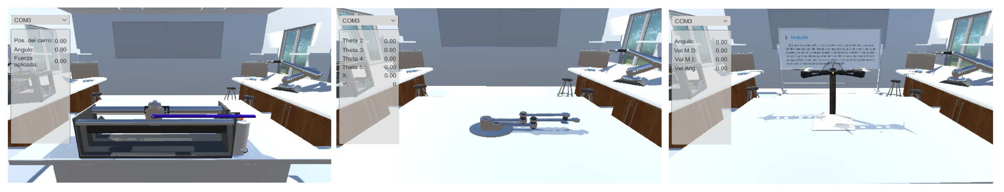
2.1. Platform Design

Taking into consideration the findings in Rossiter et al. (2020), and the necessities of our students, a platform for practicing control engineering was designed with the following characteristics:
  • As in simulation software, the platform must be able to emulate the behavior of different electromechanical systems. The input and output variables should be available for measurement and control. Plant emulation allows students to control different systems on their own computers (unlike physical labs).
  • As in hands-on laboratories, the platform must allow to control and monitor the system variables through external electronic devices so that interaction between the virtual system and the real world is possible. This feature helps the student to practice the implementation of controllers in real hardware (unlike virtual labs).
  • The platform enables virtual electromechanical systems to be visualized with different technologies, such as virtual laptops and virtual-reality MR headsets (which may increase student motivation).
The MR laboratories proposed in this work consist of two elements: a virtual environment designed in Unity, where a virtual system can be visualized; and an embedded system that emulates the behavior of the electromechanical system by computing the numerical solution of its differential equation.
Regarding the embedded system, a differential equation representing the behavior of the electromechanical system is computed on a microcontroller, which allows to send/receive electrical signals to/from other physical devices representing the input and output variables of the system. The embedded system also sends the information of the system’s variables to the Unity application for animating the virtual electromechanical system within the virtual environment.
With regard to the virtual environment, depending on the user’s preference, it can be displayed using an Oculus virtual reality headset or a mobile device. The students/practitioners can interact with the virtual environment by walking around it and getting closer to the virtual systems that are located in a workstation as if they were in a real laboratory. However, the virtual environment must be designed focusing on a step-by-step protocol, as suggested by Vergara et al. (2019), to help the students improve knowledge building. In the case reported here, a practice guide was first drafted, describing the steps of the virtual experiment to be performed by the students. This guide was used to decide the features that were desirable or required by the platform for performing the practice (e.g., input and output variables’ visualization was required in real time so the student could visualize the system behavior and the variables’ values at the same time; also, being able to plot these variables was desirable but not mandatory since these plots can be obtained from the control microcontroller IDE). The practice step sequence corresponded with Kolb’s cycle; this will be explained in detail in Section 4.2. One of the main characteristics of the MR laboratory is its versatility. The students or the instructor can design their own electromechanical system using CAD software, and they can control the system using several electronic devices, such as microcontrollers, operational amplifiers, or Programmable Logic Controllers (PLCs).
Initially, three electromechanical systems were designed in CAD software and then integrated in our MR laboratories: an inverted pendulum, a SCARA robot, and a propeller-based seesaw system; these are depicted in Figure 2. A video can be seen at the following link: https://youtu.be/6e5Tf8lCWes (accessed on 2 July 2025), demonstrating the interaction between a user/student and the MR laboratories.

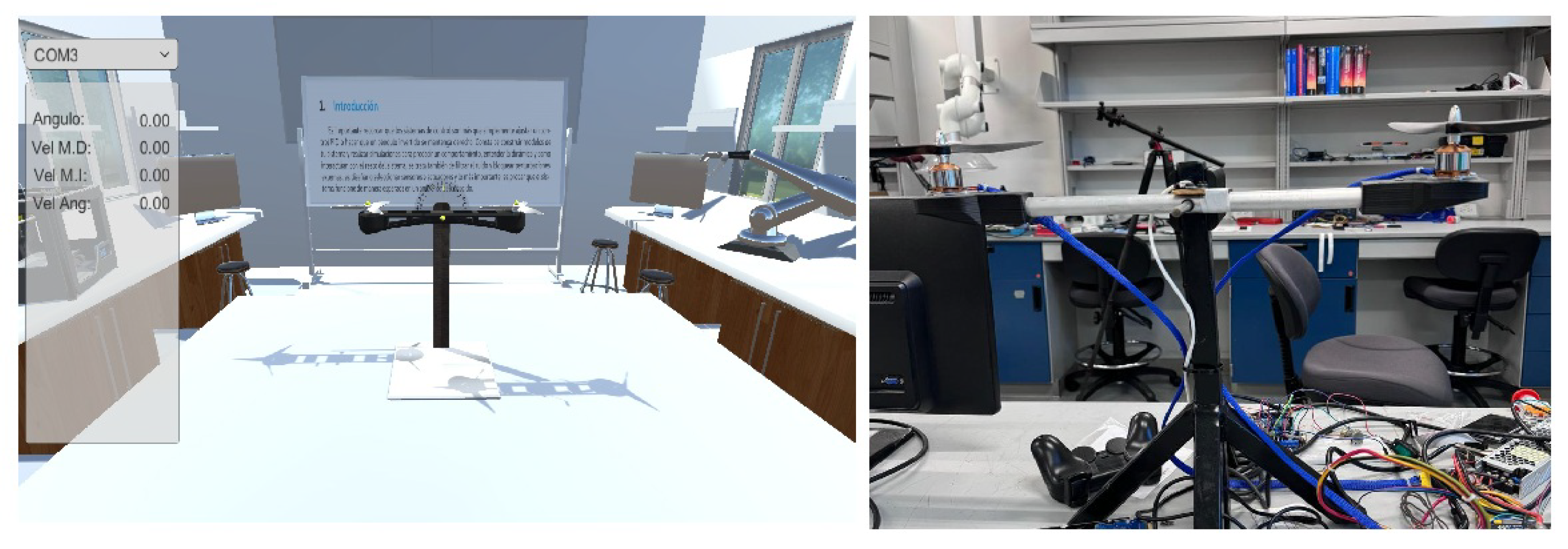
2.2. Virtual Propeller-Based Seesaw System

As a case study, a propeller-based seesaw system is presented. It was designed using CAD software for teaching control concepts (see the third image on the right in Figure 2). It consists of a beam and two rotors located at both ends. Its dynamic behavior can be described through the following differential equation:
J θ ¨ ( t ) = τ ( t ) C θ ˙ ( t )
where θ represents the angle of the beam, τ is the torque due to the right and left rotors, C is the viscous friction coefficient, and J is the moment of inertia of the system. The torque τ is described by the following equation:
τ ( t ) = L f r ( t ) L f l ( t )
where f r and f l represent forces generated by the right and left rotors, respectively, and L is the distance from the center of the beam to each rotor. The forces f r and f l are described by equation f = α ω 2 , where ω is the speed of the motor and α is a constant that relates the force and the speed of the motor.
The dynamic equations of the seesaw system are codified on an ESP32 microcontroller, where the inputs of the system ( ω r and ω l ) depend on voltages that are measured with the analog-to-digital converters (ADCs) of the microcontroller, and the output of the system ( θ ) is available as a voltage by using a digital-to-analog converter (DAC).

2.3. Real Propeller-Based Seesaw System

A real propeller-based seesaw system was built, consisting of a metal structure that supports a beam by means of two rigid ball bearings that allow fluid and frictionless movement. Two motors, with their respective propellers, are located at both ends of the beam. This prototype was used as a reference to obtain the model (parameters) of the simulated seesaw system (previous subsection). Moreover, the real seesaw system was used to validate the control programs developed with the MR lab. This validation will be described in Section 3.2. Let us describe here the prototype.
The velocity of the motors, which represent the inputs of the seesaw system, are controlled by Pulse Width Modulation (PWM) signals connected to an Electronic Speed Controller (ESC). The angle of the beam, which represents the output of the seesaw system, is measured using an inertial measurement unit (IMU), MPU6050, so that the angle is also available as an electronic signal.
Figure 3 shows the MR and real versions of the seesaw system. Both systems can be driven using the same microcontroller with minimal adaptations (for measuring the angle θ and changing the velocities ω r and ω l ), leaving the control algorithm unchanged.
In the case of the virtual propeller-based seesaw system, the controller device uses one ADC for obtaining the value of angle θ and two DACs for changing the velocities ω r and ω l ; this is depicted in Figure 4. In the case of the real propeller-based seesaw system, the controller device uses a serial I2C bus for obtaining the data from the IMU to compute θ and two PWM channels connected to the motor drivers for changing the velocities ω r and ω l ; this is shown in Figure 5.

3. Validation for Control Implementation: MR Lab vs. Hands-On Lab

This section explains how MR laboratories enable the testing of control algorithms designed for a virtual electromechanical system to follow a desired trajectory. To validate the MR lab, the obtained control algorithm is implemented on the real system using the same physical controller device and control law.

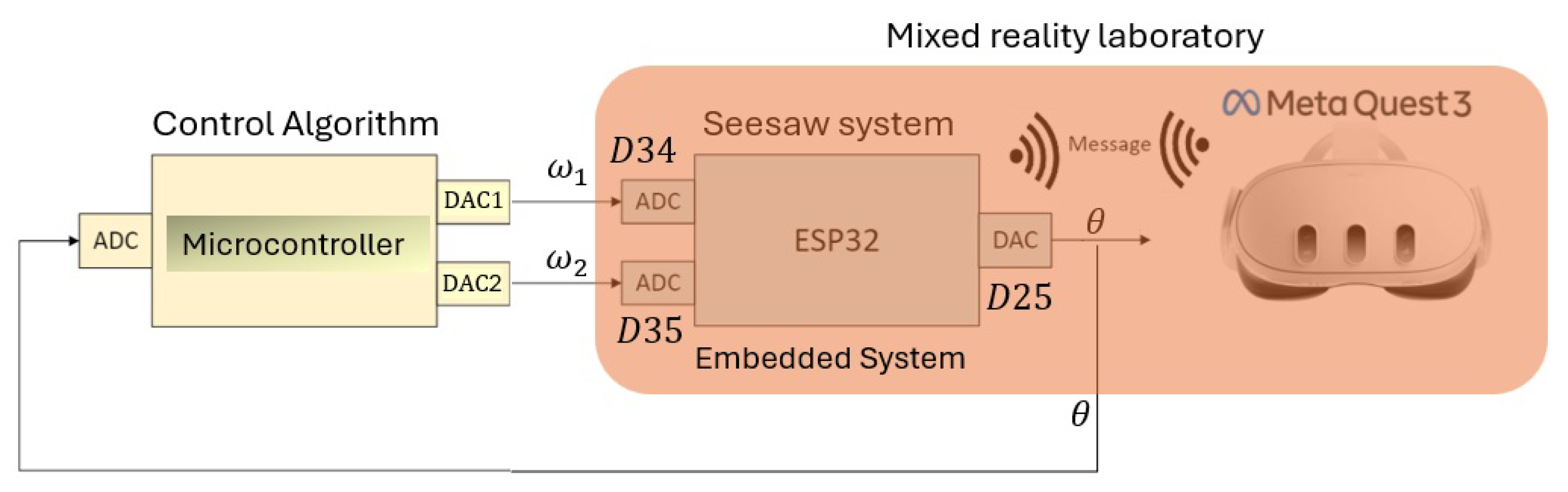
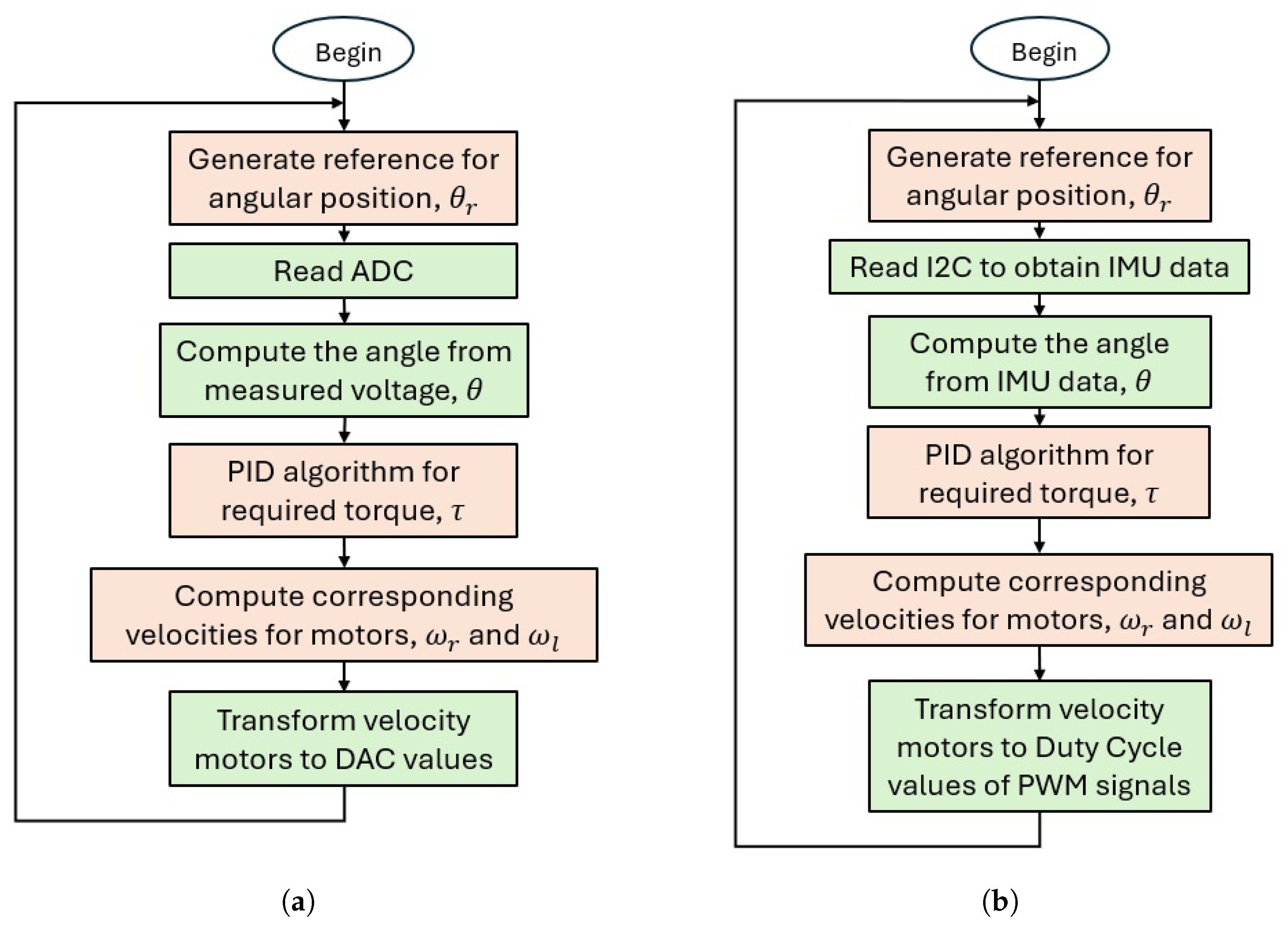
3.1. Control Algorithm for the MR Laboratory

Taking into account the closed-loop diagram depicted in Figure 4, an example of a control algorithm for controlling the behavior of the propeller-based seesaw system is presented. A flow diagram of the code to implement a Proportional–Integral–Derivative (PID) controller within a microcontroller is shown in Figure 6a. During a sampling period, a reference value of the angular position θ r of the system is generated. Then, the ADC module is read and the value of the angular position of the virtual seesaw system θ is computed. Afterwards, a PID algorithm computes the required torque τ so that the angular position of the seesaw system can follow the reference value. Then, the corresponding motor velocities ω r and ω l are computed from the torque value. Finally, these values are transformed to DAC values. To illustrate this procedure, a fragment of the code implemented on an Arduino Mega microcontroller is presented in Listing 1.
The following link includes a video of the seesaw system (the MR laboratory is running on a laptop) controlled using a PID controller with the Arduino microcontroller (Listing 1): https://youtu.be/EQzyIUAkhww?si=FNtDuzeEKwIkyfdf (accessed on 2 July 2025). The required angular position of the beam is changing over time from 20 °, 10 °, 0°, 10°, and 20°. The angular position of the seesaw system properly follows those references.
Listing 1. Arduino code fragment for PID control.
time = time + dt;

// Angular position reference
if  (time < 15) {
thetaref = -20 / 57.2956;
}
else if  (time >= 15 && time < 25) {
thetaref = -10 / 57.2956;
}
else if  (time >= 25 && time < 35) {
thetaref = 0;
}
else if  (time >= 35 && time < 45) {
thetaref = 10 / 57.2956;
}
else  {
thetaref = 20 / 57.2956;
}

// Read sensors :(0 V, 5 V)->(-pi/2, pi/2)
theta=1.5708∗((float(analogRead(A0))-512))/511 + 0.0349;

// PID Controller
error = thetaref - theta;
der_e = (error - error1) / dt;
error1 = error;
int_e = int_e + error ∗ dt;
m = Kp ∗ error + Ki ∗ int_e + Kd ∗ der_e;

Torque = m;

// Decoupling (Thrust, Torque) -> (w1, w2)
radical1 = (Thrust ∗ 0.5 + Torque / (2 ∗ L)) / alpha;
radical2 = (Thrust ∗ 0.5 - Torque / (2 ∗ L)) / alpha;
if (radical1 < 0) { radical1 = 0; }
if (radical2 < 0) { radical2 = 0; }
w1 = sqrt(radical1);
w2 = sqrt(radical2);

// PWM signals
Output1 = int(w1 ∗ 255 / 5);
Output2 = int(w2 ∗ 255 / 5);
if (Output1 > 255) { Output1 = 255; }
if (Output2 > 255) { Output2 = 255; }

analogWrite(9, Output1);
analogWrite(10, Output2);

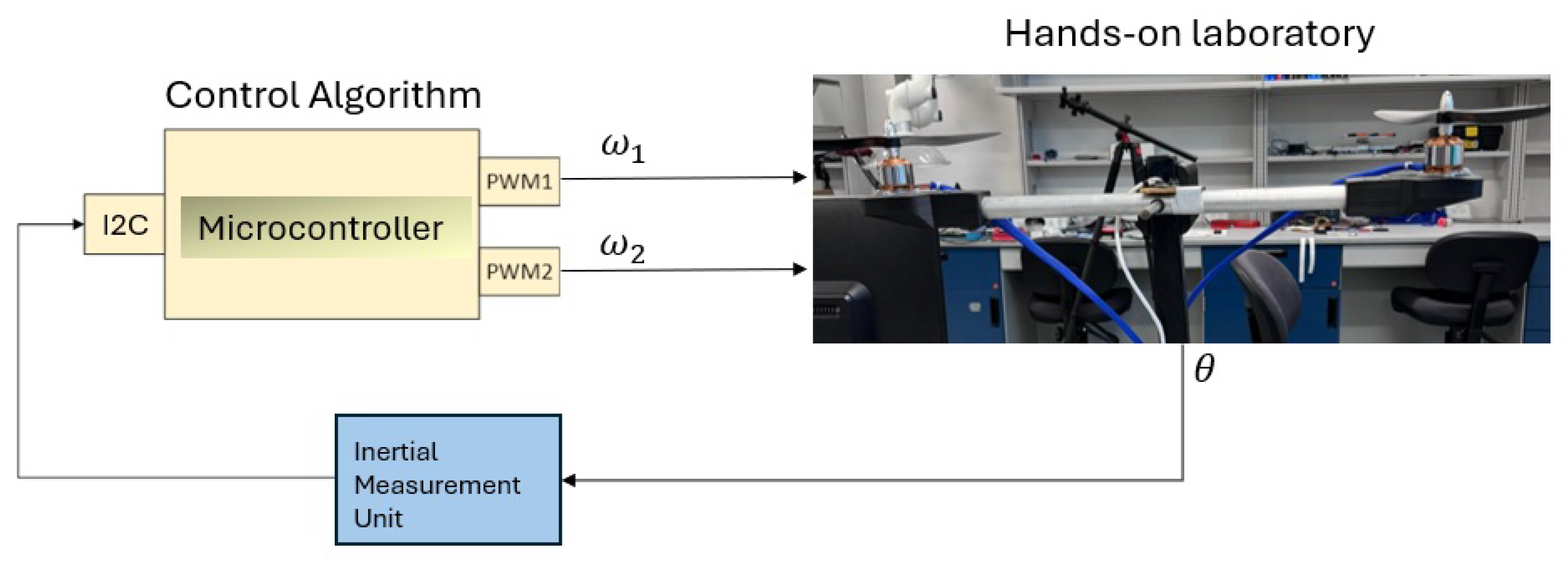
3.2. MR Lab Validation: Implementing the Control Algorithm in the Real Seesaw System

Taking into account the closed-loop diagram depicted in Figure 5, the previous control algorithm designed for controlling the behavior of the propeller-based seesaw system in the MR lab is slightly modified to implement the controller for the real seesaw prototype. A flow diagram of the code to implement the Proportional–Integral–Derivative (PID) controller in the physical seesaw system is shown in Figure 6b. Notice that the only differences between the flow diagrams used in the MR lab and in the real system (Figure 6) are how the angle of the system is measured (with an ADC/with an IMU) and how the motor velocities are changed (using the DACs/using the PWMs and ESC drivers).
The link https://youtu.be/qqK2Rpwm9dA?si=zrmdhaGatvkLsIC7 (accessed on 2 July 2025) shows a video of the implementation of the same PID controller (adjusted for the MR lab) to the physical seesaw system. The required angular position of the beam is changing over time from 10 °, 0°, 10°, and 20°. The angular position of the seesaw system properly follows those references in the same way as for the virtual system.
This practice validates that the implementation procedure required for controlling the MR lab is essentially the same used for controlling the real seesaw system; thus, students can effectively develop control implementation skills by using the MR lab.

4. Implementation on a Learning Experience: Measuring Motivation and Learning Outcomes

The MR laboratories have been implemented as part of the mechatronics curriculum at our institution. In this section, we present the motivation and learning outcomes achieved through the use of this educational innovation, including measurable data via surveys the students answered regarding their impressions of using the MR laboratories.
Two methodologies were followed: one for measuring the students’ ability to implement a PID control and another one for measuring the students’ motivation.
For the former, it consists of the following:
  • A pre-test for evaluating the previous knowledge of the students and using it to form groups of students to avoid biased results of the learning outcome measure after using the MR labs.
  • The laboratory practice for the MR labs was implemented following a guide specially designed for this purpose, which implements Kolb’s cycle.
  • A post-test designed by a collegiate group of subject matter experts was administered to measure the students’ ability to implement a PID control.
For the latter, it consists of the following:
  • An Intrinsic Motivation Inventory (a well-established test for assessing motivation in educational interventions) was administered to students after they used the MR laboratory.

4.1. Contextualization

The Mechatronics Engineering program and the Robotics and Systems program at our institution offer four courses related to control systems, which are
  • Industrial Automation.
  • Modeling and Automation.
  • Design of Control Systems.
  • Analysis of Control Systems.
For the first two courses, a lab session about PID controllers was carried out using the seesaw system. For the other two, a lab session about state feedback controllers was implemented using the seesaw system of the MR laboratories.
The students receive a guide for conducting the laboratory practice. It explains the mathematical model that represents the behavior of the system. The inputs and outputs of the system are also described. A kit with the embedded system and the virtual environment (the MR laboratory) is provided to the students. They can follow the instructions for interacting with the virtual seesaw system in open loop, that is, without a control action, to understand that the system is unstable.

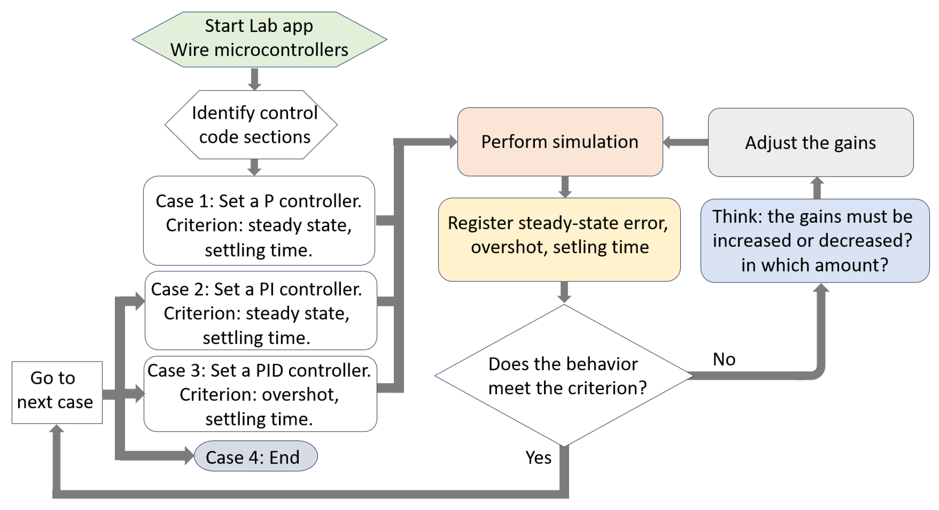
4.2. Practice Design Based on Kolb’s Experiential Learning Cycle

Figure 7 shows a flow diagram of the practice design. It summarizes the practice guide provided to the students, which consists of 7 pages of detailed instructions. The first two steps (start lab app and wire microcontrollers; identify control code sections) involve the material preparation and the first contact with the lab. Next, the student is required to implement, in sequence, a P controller, a PI controller, and a PID controller in the STM32F0 microcontroller. In each case, the student performs a cycle of four activities: (1) “Perform a simulation” in the MR lab; (2) “Register the steady-state error, overshot and settling time” with the data obtained from the control microcontroller; (3) if the behavioral criterion is not fulfilled, the student must decide if the controller gains must be increased or decreased depending on the current and previous observations and his/her theoretical knowledge; and (4) the student must adjust the gains and iterate the cycle. Once the criterion is fulfilled, the student must perform the cycle for the next controller (starting with the P controller, then the PI controller, and finally the PID controller). For the P controller, the performance criterion is a given admissible steady-state error and settling time (an offset error will remain with this controller; the student must adjust the gain so the steady-state error lies below a given bound while maintaining a fast enough settling time). Moreover, for this first controller, the students are also required to adjust the sampling time. For the PI controller, the steady-state error must be eliminated, maintaining a fast enough settling time. Finally, for the PID controller, the criterion includes an overshot requirement, so the overshot is lower than a given bound.
The four activities in the cycle correspond with Kolb’s experiential learning cycle (Kolb, 2014), which is a well-accepted framework for achieving learning objectives. Kolb’s cycle states that the learning process has two dimensions: transformation and prehension. Each dimension consists of two stages. The prehension dimension includes Concrete Experience and Abstract Conceptualization, while the transformation dimension comprises Reflective Observation and Active Experimentation. According to Abdulwahed and Nagy (2009), hands-on laboratories typically fail to support full learning construction because, during hands-on activities, students tend to focus only on the active experimentation stage, often missing at least one of the other stages of the cycle.
Regarding the practice design, the lab preparation and “Perform simulation” activity corresponds to the Concrete Experience stage. The “Register steady-state error, overshot, and settling time” activity corresponds to the Reflective Observation stage, where the student takes measurements of the system performance, calculates the required performance parameters, and compares them against the required criterion. The visualization of the plant in either a screen or a VR device allows the student to connect the obtained performance parameters with the seesaw behavior, enhancing the observation experience and gaining intuition regarding the system behavior. The activity “Think: the gains must be increased or decreased? in which amount?” involves the Abstract Conceptualization stage since the student must construct a system behavioral pattern with the results obtained in the current and previous iterations, matching these observations with his/her theoretical knowledge on the control system behavior to make a proper decision. The activity “Adjust gains” together with the iteration of the simulations correspond to the Active Experimentation stage. This cycle is repeated for the three controllers, each time gaining wider comprehension of the system performance and the roles of the controller terms.
After the practice is completed, a report must be submitted with the obtained data from all iterations with the student’s conclusions.
Different practices can be designed for implementing other control methods (e.g., state feedback, LQR, observer design, etc.). In such cases, the proposed cycle can be used just by properly defining the performance criterion and the control parameters (gains) to be adjusted.

4.3. Student Experience Using the MR Laboratories

As an example of the student outcome when performing the practice, a portion of the code implemented on an STM32 microcontroller by a student during the practice is shown in Listing 2. This code demonstrates the implementation of a PID control algorithm.
Listing 2. STM32 code fragment for PID control.
// Reference signal
if (t < 6000) {
thetaref = -20 / 57.2956;
}
else if (t < 12000) {
thetaref = 0 / 57.2956;
}
else if (t < 18000) {
thetaref = 20 / 57.2956;
}
else {
t = 0;
}

// Read angle value with ADC
// Start ADC conversion ADC (pag. 266)
ADC1->CR |= ADC_CR_ADSTART;
// Wait for finish conversion (pag. 247)
while ((ADC1->ISR & ADC_ISR_EOC) == 0);
// Read channel 3 (pag. 273)
analogRead3 = ADC1->DR;

// Scaling from (0 V, 3.3 V) -> (-pi/4, pi/4) radians
theta = 0.7854 * (analogRead3 - 2048) / 2048;

// PID Controller
error = thetaref - theta;
derror = (error - error_1) / dt;
integral = integral + error * dt;
Torque = Kp * error + Kd * derror + Ki * integral;

error_1 = error;

// Decoupling (Thrust, Torque) -> (w1, w2)
radical1 = (Thrust * 0.5 + Torque / (2 * L)) / alpha;
radical2 = (Thrust * 0.5 - Torque / (2 * L)) / alpha;
if (radical1 < 0) { radical1 = 0; }
if (radical2 < 0) { radical2 = 0; }

w1 = sqrt(radical1);
w2 = sqrt(radical2);

Output1 = (w1 * 255 / 3.3);
Output2 = (w2 * 255 / 3.3);
if (Output1 > 255) { Output1 = 255; }
if (Output2 > 255) { Output2 = 255; }

TIM3->CCR4 = Output1;
TIM3->CCR3 = Output2;
In the link https://youtube.com/shorts/e0GntfThqcw?si=YzD4synN3Zyi26mm (accessed on 2 July 2025), a video of the controlled virtual seesaw system is shown. The MR laboratory is running on a Meta Quest 3 headset. The required angular position of the beam is changing over time from 20 °, 0°, and 20°. The angular position of the seesaw system properly follows those references.

4.4. Results on Motivation

The Intrinsic Motivation Inventory (IMI) (Edward McAuley & Tammen, 1989) was used to assess participants’ subjective experience related to these activities using the MR laboratories. The instrument yields six subscale scores assessing participants’ interest/enjoyment, perceived competence, effort, value/usefulness, felt pressure and tension, and perceived choice while performing the activity.
A total of 69 students completed the questionnaire. The distribution of the grades given by the students for each question can be seen in Figure 8 in the form of a box and whisker plot. The evaluation range was from 0 to 7, where 0 indicates that the student completely disagrees and 7 indicates that he or she strongly agrees with each assumption. In the topic called interest, almost 74% of the students found the lab interesting to complete, and only one gave it a low grade. This parameter is important because it demonstrates that the lab achieved a critical educational goal: it actively engaged and motivated the majority of the students, creating a positive and likely effective learning experience. This is a strong indicator of pedagogical success and provides valuable data for continuous improvement. It goes beyond simple completion rates to show that the activity was not just completed but was meaningful and valued by the learners themselves. For the second assumption, so-called competence, 55 of the students gave a high mark (between 6 and 7) considering they felt rather competent after working on this activity. Thus, it effectively promoted a fundamental psychological need (competence) in most students, which directly led to high satisfaction and created fertile ground for future learning, engagement, and persistence.
Nearly 61% of the students answered that they put a great deal of effort into developing this laboratory. It is important to emphasize that this statistic is not only about hard work but also shows that the laboratory successfully turned students from passive recipients into active developers, encouraging engagement, critical thinking, problem-solving, and persistence in the majority of the class. In the case of the topic named pressure, there was greater fragmentation in the responses, as can be seen in the corresponding box in Figure 8. This indicates that students encountered different levels of difficulty when completing the lab. For perceived choice, the distribution is very compact, with 78% of the respondents scoring between 6 and 7, stating that they wanted to complete the lab. It highlights a critical mass of strong, positive intrinsic motivation within the group, which is a fundamental driver of successful learning experiences, effective educational design, and positive outcomes. In the case of usefulness, 87% of the students considered the mixed signal laboratories to be valuable to them. This result accentuates that laboratories are transformative spaces where theoretical knowledge converges with the development of practical skills, professional preparation, and inclusive education.
Based on the results, we can conclude that students demonstrate intrinsic motivation to learn control engineering concepts through the use of MR laboratories. In addition, they show confidence in the implementation of control algorithms on microcontrollers, a skill not covered in previous coursework.

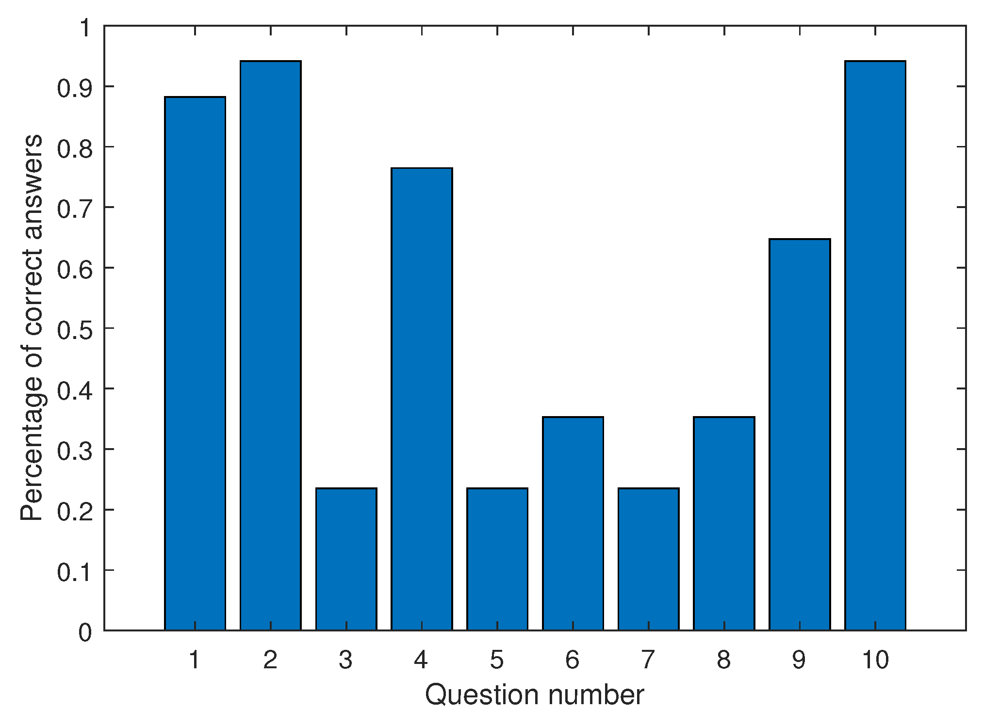
4.5. Results on Learning Control Concepts

A disciplinary control test was administered to the students after participating in the MR laboratory implementing a PID controller. The test was designed by a team of six professors with experience in teaching automatic control. The questionnaire consisted of ten multiple-choice questions, with three answer options (only one correct) plus the answer “I have no idea”, included to avoid randomly chosen correct answers. All the questions were related to a pseudo-code that implements a PID controller in a microcontroller for regulating the speed of a DC motor, as shown in Figure 9.
The questions can be clustered as follows:
  • PID control: Q1 and Q6 ask to identify the type of controller implemented by the pseudo-code and the most relevant term in the implemented controller.
  • Sampling time: Q2, Q3, and Q10 ask to identify the sampling time, determine the consequences of modifying the sampling time, and determine the number of control cycles per second.
  • Noise effects: Q4 and Q8 ask about the influence of measurement noise and the effect of high-frequency noise on the PID control terms.
  • Control modifications: Q5 and Q7 ask about the pseudo-code lines to be replaced if a different control law is required (the control law is given in the question in continuous time) and the consequences of replacing the control law by a proportional controller with positive gain.
  • Control constraints: Q9 asks about how to implement control action bounds.
Figure 10 shows the results obtained from the disciplinary test. According to this, the students identify the pseudo-code lines for implementing the PID (Q1) and identify the pseudo-code line for defining the sampling time (Q2), understanding the role of sampling (Q10). With a slightly lower percentage, the students also understand the influence of measured noise (Q4) and know how to implement control bounds (Q9). On the other hand, the students fail to determine the consequences of modifying the sampling time (Q3), the effect of noise on the PID control terms (Q8), the consequences of replacing the control law via proportional control with positive feedback (Q7), and how to modify the pseudo-code for implementing a control law given in continuous time (Q5).
The results show that students understand the key lines of code related to PID controller implementation in pseudo-code: PID control law implementation, sampling time definition, and control bound implementation. Nevertheless, the students fail to determine the consequences of control law modifications and how to implement other control laws given in continuous time, issues more related to theoretical concepts rather than implementation aspects. In other words, the practice helped students to understand the implementation of PID controllers but not necessarily to answer deeper control theory questions.

5. Concluding Remarks

With regard to the technological tool presented in this work, MR laboratories represent an educational tool for teaching control engineering concepts, in which students can design and evaluate control algorithms in a safe environment. Particularly, the MR laboratories presented in this work have three fundamental characteristics: (1) the virtual system in the MR laboratory can be controlled using real electronic devices; (2) the MR laboratory can be displayed via laptops, mobile devices, and virtual/augmented reality headsets; and (3) the designed control algorithms are applicable to equivalent real systems with minor modifications.
Technological obsolescence is a critical factor to consider in the long-term viability of the mixed reality laboratory proposed in this work. As pointed out in Grévisse (2022), even successful virtual laboratories can become useless due to outdated technologies because of both hardware and software changes. In the particular case of that work, the end of support for Flash (a widely used but eventually deprecated technology) represented a risk for the continuity of an e-learning course. Similarly, Vergara et al. (2020) emphasized how obsolescence in virtual reality learning environments can degrade the educational experience, particularly in terms of motivation and interactivity, unless continuous updates are carried out.
To prevent obsolescence, the MR laboratories were designed with software, hardware, and communication flexibility in mind. The virtual environment was developed in Unity, with support for updates and compatibility across desktop, VR (Meta Quest 2), and AR (Meta Quest 3) platforms (see Figure 11) to maintain usability and engagement. Regarding the hardware, a modular firmware allowed migration from Arduino Mega to the more advanced ESP32. Communication uses standardized protocols—USB, Bluetooth, and Wi-Fi—ensuring interoperability with current and future devices.
With regard to the mixed reality (MR) laboratories implemented in the Mechatronics Engineering curriculum, Kolb’s experiential learning cycle proved to be an effective pedagogical strategy for both learning and student motivation. A laboratory practice was designed to integrate each stage of the cycle: Concrete Experience, Reflective Observation, Abstract Conceptualization, and Active Experimentation. This structure allowed students not only to interact with the virtual system but also to reflect and make informed decisions based on their theoretical knowledge, fostering deeper and more meaningful learning.
The survey responses indicate that the majority of the students experienced high levels of motivation, involvement, and confidence while completing the activity. Strong scores in areas such as interest, usefulness, and voluntary participation reflect the effectiveness of the learning environment in promoting intrinsic motivation—a key factor for meaningful and enduring learning. Although the disciplinary test results confirm that the students grasped the practical implementation of control concepts, they also reveal gaps in theoretical understanding. This suggests that, while the application of Kolb’s learning cycle is beneficial, it should be supplemented with activities that reinforce theoretical analysis to ensure more comprehensive education in automatic control.

Author Contributions

Conceptualization, A.G.-C., C.R.V. and M.N.-G.; data curation, A.G.-C.; funding acquisition, A.G.-C., C.R.V. and M.N.-G.; investigation, A.G.-C., C.R.V. and M.N.-G.; methodology, A.G.-C. and A.R.-A.; project administration, A.G.-C. and M.N.-G.; resources, R.C.-E., R.A.M.-F. and M.N.-G.; software, R.C.-E., R.A.M.-F. and A.R.-A.; validation, R.C.-E. and R.A.M.-F.; writing—original draft, R.C.-E., R.A.M.-F. and M.N.-G.; writing—review and editing, A.G.-C., C.R.V. and A.R.-A. All authors have read and agreed to the published version of the manuscript.

Funding

This research received no external funding.

Institutional Review Board Statement

Ethical review and approval were waived for this study due to NULL OR LOW LEVEL OF RISK OF PARTICIPANTS.

Informed Consent Statement

Informed consent was obtained from all subjects involved in the study.

Data Availability Statement

The original contributions presented in this study are included in the article. Further inquiries can be directed to the corresponding author.

Acknowledgments

The authors wish to acknowledge the financial and technical support of Writing Lab, Institute for the Future of Education, Tecnologico de Monterrey, Mexico, in the production of this work.

Conflicts of Interest

Ricardo Corona-Echauri is employed by Bosch Mexico. Ramón Alejandro Meza Flores is employed by John Deere. The remaining authors declare that the research was conducted in the absence of any commercial or financial relationships that could be construed as a potential conflict of interest.

Abbreviations

The following abbreviations are used in this manuscript:
MRMixed Reality
PIDProportional–Integral–Derivative
ARCSAttention, Relevance, Confidence, and Satisfaction
IMIIntrinsic Motivation Inventory
CADComputer-Aided Design
PLCProgrammable Logic Controller
ADCAnalog-to-Digital Converter
DACDigital-to-Analog Converter
PWMPulse Width Modulation
ESCElectronic Speed Controller
IMUInertial Measurement Unit

References

  1. Abdulwahed, M., & Nagy, Z. K. (2009). Applying kolb’s experiential learning cycle for laboratory education. Journal of Engineering Education, 98(3), 283–294. [Google Scholar] [CrossRef]
  2. Aebersold, M., Voepel-Lewis, T., Cherara, L., Weber, M., Khouri, C., Levine, R., & Tait, A. R. (2018). Interactive anatomy-augmented virtual simulation training. Clinical Simulation in Nursing, 15, 34–41. [Google Scholar] [CrossRef]
  3. Alsaleh, S., Tepljakov, A., Köse, A., Belikov, J., & Petlenkov, E. (2022). ReImagine lab: Bridging the gap between hands-on, virtual and remote control engineering laboratories using digital twins and extended reality. IEEE Access, 10, 89924–89943. [Google Scholar] [CrossRef]
  4. Avilés-Cruz, C., & Villegas-Cortez, J. (2019). A smartphone-based augmented reality system for university students for learning digital electronics. Computer Applications in Engineering Education, 27(3), 615–630. [Google Scholar] [CrossRef]
  5. Azimi, E., Winkler, A., Tucker, E., Qian, L., Doswell, J., Navab, N., & Kazanzides, P. (2018, July 18–21). Can mixed-reality improve the training of medical procedures? 2018 40th Annual International Conference of the IEEE Engineering in Medicine and Biology Society (EMBC) (pp. 4065–4068), Honolulu, HI, USA. [Google Scholar] [CrossRef]
  6. Aziz, F. A., Alsaeed, A. S., Sulaiman, S., Ariffin, M. K. A. M., & Al-Hakim, M. F. (2020). Mixed reality improves education and training in assembly processes. Journal of Engineering & Technological Sciences, 52(4), 598–607. [Google Scholar]
  7. Barsom, E. Z., Graafland, M., & Schijven, M. P. (2016). Systematic review on the effectiveness of augmented reality applications in medical training. Surgical Endoscopy, 30(10), 4174–4183. [Google Scholar] [CrossRef]
  8. Bayrakceken, M. K., & Arisoy, A. (2013). An educational setup for nonlinear control systems: Enhancing the motivation and learning in a targeted curriculum by experimental practices [Focus on Education]. IEEE Control Systems Magazine, 33(2), 64–81. [Google Scholar] [CrossRef]
  9. Bondin, A., & Zammit, J. P. (2025). Education 4.0 for industry 4.0: A mixed reality framework for workforce readiness in manufacturing. Multimodal Technologies and Interaction, 9(5), 43. [Google Scholar] [CrossRef]
  10. Borsci, S., Lawson, G., & Broome, S. (2015). Empirical evidence, evaluation criteria and challenges for the effectiveness of virtual and mixed reality tools for training operators of car service maintenance. Computers in Industry, 67, 17–26. [Google Scholar] [CrossRef]
  11. Calderón, R. R., & Arbesú, R. S. (2015). Augmented reality in automation. Procedia Computer Science, 75, 123–128. [Google Scholar] [CrossRef]
  12. Chen, C.-M., Li, M.-C., & Tu, C.-C. (2024). A mixed reality-based chemistry experiment learning system to facilitate chemical laboratory safety education. Journal of Science Education and Technology, 33(4), 505–525. [Google Scholar] [CrossRef]
  13. de Belen, R. A. J., Nguyen, H., Filonik, D., Favero, D. D., & Bednarz, T. (2019). A systematic review of the current state of collaborative mixed reality technologies: 2013–2018. AIMS Electronics and Electrical Engineering, 3(2), 181–223. [Google Scholar] [CrossRef]
  14. Edward McAuley, T. D., & Tammen, V. V. (1989). Psychometric properties of the intrinsic motivation inventory in a competitive sport setting: A confirmatory factor analysis. Research Quarterly for Exercise and Sport, 60(1), 48–58. [Google Scholar] [CrossRef] [PubMed]
  15. Frank, J. A., & Kapila, V. (2017). Mixed-reality learning environments: Integrating mobile interfaces with laboratory test-beds. Computers & Education, 110, 88–104. [Google Scholar] [CrossRef]
  16. Gavish, N., Gutiérrez, T., Webel, S., Rodríguez, J., Peveri, M., Bockholt, U., & Tecchia, F. (2015). Evaluating virtual reality and augmented reality training for industrial maintenance and assembly tasks. Interactive Learning Environments, 23(6), 778–798. [Google Scholar] [CrossRef]
  17. Gonzalez-Franco, M., Pizarro, R., Cermeron, J., Li, K., Thorn, J., Hutabarat, W., Tiwari, A., & Bermell-Garcia, P. (2017). Immersive mixed reality for manufacturing training. Frontiers in Robotics and AI, 4, 3. [Google Scholar] [CrossRef]
  18. Grévisse, C. (2022, October 17–21). Flash, who? On the obsolescence of digital technology and its impact on e-learning applications: A case study. 2022 XVII Latin American Conference on Learning Technologies (LACLO) (pp. 1–7), Armenia, Colombia. [Google Scholar] [CrossRef]
  19. Hernández-de Menéndez, M., Vallejo Guevara, A., & Morales-Menendez, R. (2019). Virtual reality laboratories: A review of experiences. International Journal on Interactive Design and Manufacturing, 13(3), 947–966. [Google Scholar] [CrossRef]
  20. Jailly, B., Gravier, C., Preda, M., & Fayolle, J. (2011). Interactive mixed reality for collaborative remote laboratories. In Proceedings of the third international acm workshop on multimedia technologies for distance learning (pp. 1–6). Association for Computing Machinery. [Google Scholar] [CrossRef]
  21. Kaur, D. P., Mantri, A., & Horan, B. (2021). A framework utilizing augmented reality to enhance the teaching–Learning experience of linear control systems. IETE Journal of Research, 67(2), 155–164. [Google Scholar] [CrossRef]
  22. Kolb, D. A. (2014). Experiential learning: Experience as the source of learning and development. FT Press. [Google Scholar]
  23. Kucera, E., Haffner, O., & Leskovský, R. (2018, January 31–February 3). Interactive and virtual/mixed reality applications for mechatronics education developed in unity engine. 2018 Cybernetics & Informatics (K & I) (pp. 1–5), Lazy pod Makytou, Slovakia. [Google Scholar] [CrossRef]
  24. Martin, J., & Bohuslava, J. (2018, January 31–February 3). Augmented reality as an instrument for teaching industrial automation. 2018 Cybernetics & Informatics (K&I) (pp. 1–5), Lazy pod Makytou, Slovakia. [Google Scholar] [CrossRef]
  25. May, D., Terkowsky, C., Varney, V., & Boehringer, D. (2023). Between hands-on experiments and Cross Reality learning environments—Contemporary educational approaches in instructional laboratories. European Journal of Engineering Education, 48(5), 783–801. [Google Scholar] [CrossRef]
  26. Mejías Borrero, A., & Andújar Márquez, J. (2012). A pilot study of the effectiveness of augmented reality to enhance the use of remote labs in electrical engineering education. Journal of Science Education and Technology, 21, 540–557. [Google Scholar] [CrossRef]
  27. Mendez, J. A., & Gonzalez, E. J. (2011). Implementing motivational features in reactive blended learning: Application to an introductory control engineering course. IEEE Transactions on Education, 54(4), 619–627. [Google Scholar] [CrossRef]
  28. Muñoz de la Peña, D., Domínguez, M., Gomez-Estern, F., Reinoso, O., Torres, F., & Dormido, S. (2022). Overview and future trends of control education. IFAC-PapersOnLine, 55(17), 79–84. [Google Scholar] [CrossRef]
  29. Müller, D., Bruns, F. W., Erbe, H.-H., Robben, B., & Yoo, Y.-H. (2007). Mixed reality learning spaces for collaborative experimentation: A challenge for engineering education and training. International Journal of Online Engineering, 3(4). [Google Scholar] [CrossRef]
  30. Odeh, S., Shanab, S. A., Anabtawi, M., & Hodrob, R. (2013). A remote engineering lab based on augmented reality for teaching electronics. International Journal of Online Engineering (iJOE), 9(S5), 61–67. [Google Scholar] [CrossRef]
  31. Panza, S., Wi, Y., Invernizzi, D., Cescon, M., & Lovera, M. (2024). Experiential learning in automatic control using quadrotor UAVs. IFAC-PapersOnLine, 58(16), 123–128. [Google Scholar] [CrossRef]
  32. Peters, E., Heijligers, B., de Kievith, J., Razafindrakoto, X., van Oosterhout, R., Santos, C., Mayer, I., & Louwerse, M. (2016, September 7–9). Design for collaboration in mixed reality: Technical challenges and solutions. 2016 8th International Conference on Games and Virtual Worlds for Serious Applications (VS-GAMES) (pp. 1–7), Barcelona, Spain. [Google Scholar] [CrossRef]
  33. Rahok, S. A., Oneda, H., Osawa, S., & Ozaki, K. (2019). Motivation system for students to learn control engineering and image processing. Journal of Robotics and Mechatronics, 31(3), 405–411. [Google Scholar] [CrossRef]
  34. Reck, R. M. (2016). Experiential learning in control systems laboratories and engineering project management [Doctoral dissertation, University of Illinois—Urbana-Champaign]. Available online: https://dissertation.com/abstract/2071125 (accessed on 2 July 2025).
  35. Rodriguez, J., Esparragoza, I. E., & Ocampo, J. R. (2017, June 25–28). Comparison of intrinsic motivation of freshmen engineering students as they participate in a multinational design project. 2017 ASEE Annual Conference & Exposition, Columbus, OH, USA. Available online: https://peer.asee.org/28055 (accessed on 2 July 2025).
  36. Rossiter, J., Zakova, K., Huba, M., Serbezov, A., & Visioli, A. (2020). A first course in feedback, dynamics and control: Findings from 2019 online survey of the international control community. IFAC-PapersOnLine, 53(2), 17264–17275. [Google Scholar] [CrossRef]
  37. Sandoval Pérez, S., Gonzalez Lopez, J. M., Villa Barba, M. A., Jimenez Betancourt, R. O., Molinar Solís, J. E., Rosas Ornelas, J. L., Riberth García, G. I., & Rodriguez Haro, F. (2022). On the use of augmented reality to reinforce the learning of power electronics for beginners. Electronics, 11(3), 302. [Google Scholar] [CrossRef]
  38. Schaf, F. M., Paladini, S., & Pereira, C. E. (2012a, April 17–20). 3D AutoSysLab prototype. 2012 IEEE Global Engineering Education Conference (EDUCON) (pp. 1–9), Marrakech, Morocco. [Google Scholar] [CrossRef]
  39. Schaf, F. M., Paladini, S., & Pereira, C. E. (2012b). 3D AutoSysLab prototype—A social, immersive and mixed reality approach for collaborative learning environments. International Journal of Engineering Pedagogy (iJEP), 2(2), 15–22. [Google Scholar] [CrossRef]
  40. Selek, M., & Kıymaz, Y. E. (2020). Implementation of the augmented reality to electronic practice. Computer Applications in Engineering Education, 28(2), 420–434. [Google Scholar] [CrossRef]
  41. Singh, G., Mantri, A., Sharma, O., Dutta, R., & Kaur, R. (2019). Evaluating the impact of the augmented reality learning environment on electronics laboratory skills of engineering students. Computer Applications in Engineering Education, 27(6), 1361–1375. [Google Scholar] [CrossRef]
  42. Su, S., Wang, R., Zhou, R., Chen, Z., & Zhou, F. (2023). The effectiveness of virtual reality, augmented reality, and mixed reality training in total hip arthroplasty: A systematic review and meta-analysis. Journal of Orthopaedic Surgery and Research, 18(1), 121. [Google Scholar] [CrossRef]
  43. Taghian, A., Abo-Zahhad, M., Sayed, M. S., & Abd El-Malek, A. H. (2023). Virtual and augmented reality in biomedical engineering. Biomedical Engineering Online, 22(1), 76. [Google Scholar] [CrossRef]
  44. Tuli, N., Singh, G., Mantri, A., & Sharma, S. (2022). Augmented reality learning environment to aid engineering students in performing practical laboratory experiments in electronics engineering. Smart Learning Environments, 9(1), 26. [Google Scholar] [CrossRef]
  45. Vargas, H., Heradio, R., Donoso, M., & Farias, G. (2023). Teaching automation with Factory I/O under a competency-based curriculum. Multimedia Tools and Applications, 82(13), 19221–19246. [Google Scholar] [CrossRef]
  46. Vergara, D., Extremera, J., Rubio, M. P., & Dávila, L. P. (2019). Meaningful learning through virtual reality learning environments: A case study in materials engineering. Applied Sciences, 9(21), 4625. [Google Scholar] [CrossRef]
  47. Vergara, D., Extremera, J., Rubio, M. P., & Dávila, L. P. (2020). The technological obsolescence of virtual reality learning environments. Applied Sciences, 10(3), 915. [Google Scholar] [CrossRef]
  48. Wattanasin, W., Chatwattana, P., & Piriyasurawong, P. (2021). Engineering project-based learning using a virtual laboratory and mixed reality to enhance engineering and innovation skills. World Transactions on Engineering and Technology Education, 19(2), 232–237. [Google Scholar]
  49. Webel, S., Bockholt, U., Engelke, T., Gavish, N., Olbrich, M., & Preusche, C. (2013). An augmented reality training platform for assembly and maintenance skills. Robotics and Autonomous Systems, 61(4), 398–403. [Google Scholar] [CrossRef]
  50. Westerfield, G., Mitrovic, A., & Billinghurst, M. (2015). Intelligent augmented reality training for motherboard assembly. International Journal of Artificial Intelligence in Education, 25, 157–172. [Google Scholar] [CrossRef]
  51. Zata, N. M., van Niekerk, T. I., & Fernandes, J. M. (2016, November 30–December 2). A process control learning factory with a plant simulation integrated to industry standard control hardware. 2016 Pattern Recognition Association of South Africa and Robotics and Mechatronics International Conference (PRASA-RobMech) (pp. 1–8), Stellenbosch, South Africa. [Google Scholar]
Figure 1. Classification of schemes for experimentation and testing of control concepts.
Education 15 00883 g001
Figure 2. Three electromechanical systems displayed in the virtual environment: an inverted pendulum, a SCARA robot, and a propeller-based seesaw system.
Education 15 00883 g002
Figure 3. MR and hands-on laboratories with the propeller-based seesaw system.
Education 15 00883 g003
Figure 4. Connection diagram of the virtual seesaw system with an external microcontroller.
Education 15 00883 g004
Figure 5. Connection diagram of the physical seesaw system with a microcontroller.
Education 15 00883 g005
Figure 6. Flow diagrams of the implemented code in the microcontroller for both the virtual and real seesaw systems. (a) Flow diagram for the virtual seesaw system. (b) Flow diagram for the real seesaw system.
Education 15 00883 g006
Figure 7. Practice diagram. The student must sequentially implement a P controller, a PI controller, and a PID controller in the STM32F0 microcontroller.
Education 15 00883 g007
Figure 8. Distribution of student responses to the survey. The crosses represent the average and the circles are outliers.
Education 15 00883 g008
Figure 9. Control system for the disciplinary test.
Education 15 00883 g009
Figure 10. Results of the disciplinary test, indicating the percentages of correct answers for each question.
Education 15 00883 g010
Figure 11. Three versions of the MR laboratories running on different hardware for visualization. (a) Laptop. (b) Meta Quest 2. (c) Meta Quest 3.
Education 15 00883 g011
Disclaimer/Publisher’s Note: The statements, opinions and data contained in all publications are solely those of the individual author(s) and contributor(s) and not of MDPI and/or the editor(s). MDPI and/or the editor(s) disclaim responsibility for any injury to people or property resulting from any ideas, methods, instructions or products referred to in the content.

