Abstract
A university course on mechanical design utilizing CAE structural analyses is reported. To develop students’ skills to solve practical open-ended engineering problems, a project-based learning (PBL) approach was adopted. The course taught not only technical skills to use CAE software but also fundamental knowledge that links theoretical and practical problems in engineering. Each segment of this course consisted of a lecture and workshop. The basic concepts of structural analysis and the background theory of finite element analysis were described in the lecture. Students conducted structural analyses in a CAE software through workshop problems and compared its results to the theory learned in the lecture. CAE structural analyses were conducted in the integrated environment of the 3D CAD software Autodesk Inventor. As the final project of the course, groups of students designed an original structure under restrictions based on functionality, strength and weight. Data of the students’ performance in related courses were collected to analyse the improvement of skills needed to solve engineering problems, and a short survey was conducted to summarize responses from the students after the course had finished. The results of the data analysis and short survey indicated that the combination of the theoretical lectures and the PBL workshop improved the students’ motivation and performance.
1. Introduction
Currently, the benefits of the reformation of the product development process using the 3D CAD system is widely recognized in numerous industries [1,2,3,4]. Since the 3D CAD system is already well distributed throughout industry, other initiatives from which to obtain extra benefits are desired. In this context, the introduction of CAE has been attracting attention from industry, since the effects of CAE, such as the reduction in time for design studies and test cycles with prototypes, can be realized in comparatively less time compared to cases in which only CAD is adopted [5,6]. Therefore, from a viewpoint of future careers for students in higher educational institutions, the ability to use CAE is promising for becoming skilled engineers.
In the mechanical design of a product, engineers have to make decisions on the appropriate shape and materials of the product to satisfy specifications related to its functions and durability, with consideration of theoretical knowledge related to mechanisms, mechanics of materials, and so on. CAE software is designed to effectively make such decisions with an intuitive user interface and has less of a focus on theoretical knowledge, so it is good tool for engineers and students to become familiar with mechanical design. However, when they try to make full use of the CAE software to design an optimized product, in-depth understanding of the background theories will be required. For example, to determine the appropriate relationship between moving parts, understanding of the equations of motion of the mechanisms is important, and knowledge on stress and strain in the mechanics of materials is essential to give sufficient strength to structural parts. Students should gain knowledge linking these theoretical studies with practical engineering applications. In this context, an educational methodology with CAE software has been sought by higher educational institutions for their courses [7,8,9].
In traditional courses in higher educational institutes, theoretical knowledge is transferred by teachers to students through lectures. This teacher-centred approach mainly focuses on the acquisition of knowledge, and little attention is paid to other important skills for students. For example, skills such as communication and collaboration skills, decision-making, problem-solving, critical-thinking and self-directed learning are quite important for students [10]. To improve the educational methodology, student-centred approaches, including project-based learning, have been widely adopted during the last 50 years [11]. Project-based learning (PBL) is a comprehensive educational approach that is designed to engage students in the investigation of authentic problems [12], and its effectiveness is mainly attributed to its ability to keep students motivated and thinking [13]. Therefore, PBL has been implemented in many higher educational institutions, including the engineering departments of universities [14,15,16,17,18]. In many of these cases, students are required to solve real-world, open-ended, ill-structured problems in teams, and their performances are assessed through methods such as oral presentations and project written reports [11].
Engineering students in higher educational institutes are taught and trained to become engineers who can solve uncertain, complex, open-ended workplace problems [19]. In spite of the suitable characteristics of the PBL approach for this objective [20,21,22], not many studies on the adoption of PBL in engineering education are found in the literature. In one of these studies, PBL was applied to the design of a product with mechanisms. In this study, an initial design of the product was first proposed with much room for improvement. Students tried to optimize the design utilizing Computer-Aided Design (CAD), multibody dynamics and the structural analysis of Computer-Aided Engineering (CAE) software in teams. It is reported that this initiative stimulated the students’ ability to solve real problems and to interactively work in a group [23]. This approach was further expanded to Computer-Aided Manufacturing (CAM) by other institutes [24]. Another study reported on the implementation of PBL, in which both background theory and engineering practices were taught. In this study, students’ competencies related to practical application were improved, along with motivation and appreciation of the students towards the discipline of engineering [25]. These studies successfully implemented PBL practices to develop the wide range of skills for engineers mentioned above.
Although the successful effect of the PBL approach is attracting attention, the challenges and limitations of the PBL approach have also been pointed out in the literature [11,12,13]. From the teachers’ point of view, the lack of training as facilitators, challenges of assessment and setting difficulty levels for problems have been pointed out. In addition, challenges and limitations related to institutions include the heavy workload to prepare and guide PBL projects and a lack of materials and resources from institutions to support PBL. From the students’ point of view, a lack of teamwork skills and self-learning skills are reported [13]. To address these, more practices of PBL, especially related to engineering, should be reported.
In this context, higher educational institutions in Japan, including Nippon Institute of Technology (NIT) and Aichi University of Technology (AUT), to which the authors belong, have been moving forward with the transformation of educational methodology. In the present initiative, the theoretical and practical side of the structural design of engineering products was taught and trained, utilizing CAE software with a project-based learning approach to improve comprehensive skills to solve engineering problems.
This paper is organized as follows: First, course design, including learning objective and activities according to the objectives, is presented in Section 2. The methodology used to collect data to assess the effectiveness of the present initiative is described in Section 3. Then, the results are reported and discussed in Section 4, and concluding remarks are given in Section 5.
2. Course Design
2.1. Learning Objectives and Activities
The curriculum of our Department of Mechanical Engineering Systems is basically composed of lectures and practical training, as shown in Figure 1. Active learning methodology with 2D/3D CAD software had already been implemented in the practical training course of mechanical design when the present initiative was started [26], which is shown in bold letters in the figure. In the present initiative, project-based learning methodology combined with CAE software was newly introduced to courses named “CAD/CAM/CAE” marked in red rectangles in the figure.
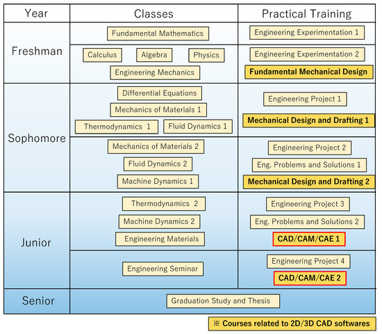
Figure 1.
Curriculum of Mechanical Engineering Systems in AUT.
The objective of the present course is to improve students’ comprehensive skills to solve open-ended engineering problems. For this purpose, each segment of this course consisted of lectures and workshops. The quality of engineering products highly depends on engineer’s knowledge, linking theory and practice. Therefore, important knowledge concerning engineering problems that had been already learned in the preceding courses were reviewed in the present lectures. In our case, the mechanics of materials was mainly reviewed because improvement in the strength of a structural part requires knowledge of this subject. In addition to this, practical training to solve engineering problems was conducted as a form of workshops. The goals and activities of each segment in the present course are shown in Table 1. Detailed descriptions of the activities are provided in the later sections.

Table 1.
Goals and learning activities for each segment of the present course.
2.2. Environments
This course was conducted in a practical room for CAD/CAM/CAE in the university. Each student was provided with a workstation in which software such as AutoCAD 2020, Inventor 2020 (Autodesk, Inc., San Francisco, CA, USA) and CATIA V5 (Dassault systemes, Inc., Dassault, France) are installed. Autodesk Inventor was mainly used for this course. All students have an account for Google Classroom, where reports can be uploaded as well as class materials can be downloaded.
2.3. Materials
The following three materials were prepared as shown in Figure 2 and provided in electric format, such as pdf or Microsoft word file through Google Classroom. Students opened the materials on the screens of their workstations in the class. They also used their own smartphones to read the workshop text when they were conducting workshop problem on the workstations.
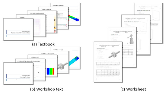
Figure 2.
Materials provided in the present course.
- (a)
- Textbook
In the aim of understanding the topics mentioned in Section 2, the main functionalities of the CAE software were summarized in the textbook, and the relationship between the functionalities and the theories were explained there.
- (b)
- Workshop text
Hands-on workshop problems to review the topics learned from the textbook were prepared in this workshop text. Step-by-step procedures for the workshop problems are summarized in it.
- (c)
- Worksheet
To write down the results from the workshop problems, worksheets with blank tables to input the results during the class were prepared. After the workshop problems were completed, students uploaded the worksheets filled with their results to the Google Classroom.
2.4. Lectures
CAE structural analyses are based on background theories in various areas, especially in mechanics of materials, as mentioned in Section 2.1. Fundamental knowledges that students should know before they start to solve engineering problems using general CAE software were chosen and taught in the lectures of the present course. The important points from these knowledges are explained in following sections.
2.4.1. Units
The coherent use of unit systems is one of the most important points to correctly solve engineering problems [27]. In general CAE software, units used for material properties and boundary conditions are not necessarily informed to users. Therefore, it is important to make the students confirm the units of quantities of the input into and output from the software. In the present course, the coherent unit system, referred to as SImm, consists of base units, including mm as length, 103 kg(ton) as mass and second as time, was described first. Then, the derivation of other units from the base units, such as MPa for stress, was introduced.
2.4.2. Boundary Conditions
Most of the CAE software, including Autodesk Inventor, used in the present course adopt the finite element method for structural analyses [28]. It is important to understand the six degrees of freedom, which consist of three translational and three rotational degrees of freedom, for defining an appropriate boundary condition in a three-dimensional finite element analysis. A correct solution cannot be obtained when six degrees of freedom are not sufficiently constrained and rigid body motion of the analytical model exists. The boundary conditions to eliminate rigid body motion without constraining the intended deformation were defined and practised in the workshop.
2.4.3. Dependence of Solution on Element Size
It is known that the solution of a finite element analysis approaches the strict theoretical one as the size of the elements decreases and the number of elements increases; in other words, the finite element mesh becomes denser [29]. However, a model with too dense of a mesh requires greater computational costs, such as memory and CPU time. In addition, the selection of element types with first- and second-order interpolation functions of displacements are available in many CAE software, including the software adopted in our course. A workshop to investigate appropriate mesh densities depending on the element types was held.
2.4.4. Unintended Stress Concentration
A finite element analysis derives a solution with finite value, even at a point where singularity exists. In the theory, stresses become infinite at corners without fillet, i.e., points and edges where concentrated load are applied [30]. The lack of this knowledge leads to the inappropriate evaluation of important results, such as the maximum stress in a analytical model. The students were advised to avoid this kind of boundary condition.
2.4.5. Reaction Force at Constrained Entities
After a successful solution of the equilibrium equation in the finite element analyses, reaction forces are calculated at locations where fixed displacements are specified as boundary conditions. Since understanding force equilibrium is essential for solving structural problems, it is important to confirm the validity of the reaction forces. Students were advised to confirm that the sum of all applied loads in the model equal to that of reaction forces.
2.4.6. Contact Conditions
In practical mechanical design, a target product in most cases, an assembly model consisting of multiple parts. It is important to know how the contact area of these multiple parts are treated in structural analyses.
The simplest way to model the contact area is to treat the multiple parts as unified parts. Although sharing nodes by using the same mesh pattern on contact surfaces of two bodies is a well-known practice, the method is sometimes difficult to use due to the complex geometry of certain parts. Therefore, special conditions to make displacement continuous at the contact surface, which is referred to as MPC [29], can be automatically applied in many CAE software.
For problems where separation and slippage between the contact surface of two bodies need to be considered, the capability to iteratively solve this nonlinear problem by calculating the equilibrium on the deformed shapes of the contact surfaces with special functions, such as penalty function [31,32], are available in some CAE software.
In some CAE software, such as Autodesk Inventor, contact conditions can be selected from physically intuitive candidates such as “glue”, ”separation” and ”slippage”. This functionality makes it unnecessary for the users to pay attention to numerical treatment of the contact surfaces.
2.4.7. Evaluation of Stress Components
Quantities such as stress and strain are calculated as tensors in the finite element analyses of CAE software. In most of the software, however, von Mises stress, which is a scalar quantity derived from the tensor, is automatically shown as a result at first because of its easier recognition. As the structural analyses are conducted for investigation on the possibility of failure in many cases, von Mises stress is not necessarily the most appropriate quantity to review the results. In the Mechanics of Materials course, students learn several failure criteria of materials, such as maximum principal stress, maximum shear stress (Tresca theory) and maximum shear strain energy (von Mises theory) [33], and were trained to choose one of the failure criteria that fit to the material used in the design. It was emphasized in the present course that the appropriate type of stress corresponding to the failure criterion should be chosen as the results need to be reviewed in the CAE structural analyses.
In the engineering calculation of stress in practical design, on a cross-section of a part where the possibility of failure is assumed, a stress component approximately averaged on a cross-section of the potential failure is evaluated to determine the appropriate size of the parts. Dimensions are calculated so that stress evaluated in the intended cross-section does not exceed the allowable stress of the materials. To do this with CAE software, engineers need to know which component of stress should be evaluated to consider the failure in the intended cross-section. For example, they should evaluate XY and ZX components of shear stress when the shear failure at a plane normal to X axis is considered. Therefore, the relationship between the index of stress components, such as τxy and τzx, and the corresponding planes were reviewed in the present class.
2.5. Workshops
2.5.1. A Plate Subjected to a Tensile Load
This workshop aimed to teach the appropriate boundary conditions to eliminate rigid body motion, first mentioned in Section 2.4.2. A tensile load in the horizontal direction is applied to a rectangular plate and a unidirectional stress state is created.
One of the easiest boundary conditions to constrain rigid body motion is to completely fix an arbitrary plane of the model in all directions. However, the problem of unidirectional tension, which is one of the fundamental problems in the mechanics of materials, needs a slightly more complex boundary conditions than that. When one end in the lateral direction of the plate is completely fixed in all degrees of freedoms and the opposite end is loaded, deformation in the transverse direction by the Poisson effect is not calculated as intended. This is because displacements in the lateral and transverse directions are both fixed at the left side of the plate, and shrinkage due to the Poisson effect in the transverse direction is constrained. The displacement distribution from the analysis is shown in Figure 3a.
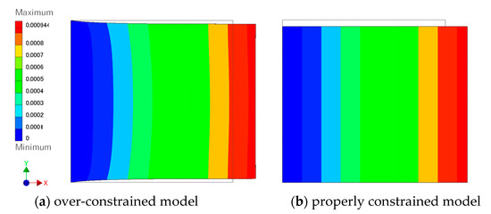
Figure 3.
Distribution of displacement of a plate under tensile load.
After explaining this result to the students, they were advised to conduct the analysis with the correct boundary conditions again as shown in Figure 3b. Merely removing boundary condition at the left side of the plate in transverse directions causes an error in the analysis due to the existence of rigid body movement, so they have to consider locations to constrain it without suppressing the intended deformation.
2.5.2. A Plate with a Hole Subjected to a Tensile Load (Stress Concentration)
The dependency of a solution on mesh density, mentioned in Section 2.4.3, was taught through this workshop problem. It is known that stress concentration occurs when a load is applied to a plate with a hole and its stress concentration factor is calculated from the ratio of the diameter of the hole to the width of the plate, as shown in a graph in Figure 4 [33]. Results from the numerical analyses with this condition were compared to the theoretical results.
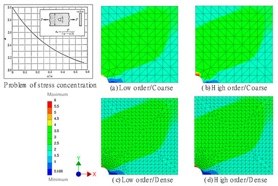
Figure 4.
Stress distribution of a plate with a hole under tensile load with various mesh patterns.
After the boundary conditions for the models with a symmetry condition were taught, a quarter model of the problem was analysed as shown in Figure 4a–d. To achieve an agreement between the numerical and theoretical results, models with a fine mesh, as shown in Figure 4c,d, are needed. The selection of low- or higher-order elements also affects the precision of the results. Students were instructed to conduct analyses with the following four models and compare each set of results:
- (a)
- Low-order elements and coarse mesh
A solution with the least precision is obtained from this model. Significant difference between the numerical and theoretical results are observed.
- (b)
- Higher-order elements and coarse mesh
An improvement in the precision of model (a) is expected by choosing higher-order elements, but the numerical solution is not completely identical to the theoretical one because of the coarse mesh.
- (c)
- Low-order elements and fine mesh
The numerical solution agrees with the theory by using a fine mesh, even with low-order elements.
- (d)
- Higher-order elements and fine mesh
Solution from this numerical model also agrees with the theory. Students were advised to confirm the fact that the fine mesh returns a precise result using whichever element types they chose.
2.5.3. Design of a Flanged Torsional Joint of Shafts
For an in-depth understanding of a practical design, a flanged torsional joint was analysed in this workshop. A mechanical drawing of this joint and engineering calculations with the theory of the mechanics of materials had been already taught in the preceding course on mechanical design [34]. Results from the analysis with CAE software conducted in the present class were compared to the theoretical one. Different design conditions, such as output of power source and rotational velocity, was assigned to each student according to their student ID number. A mechanical drawing of one of the assigned designs and its 3D model are shown in Figure 5. The following three points were mainly studied in this workshop:
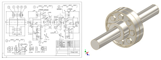
Figure 5.
Mechanical drawing and 3D model of flanged torsional joint analysed in the workshop.
- (a)
- Maximum shear stress in the shaft caused by torsional moment
To determine diameter of the shaft, the maximum shear stress is one of the most important quantities to evaluate. Therefore, it was calculated using CAE structural analysis and compared to its value calculated using the theory of torsion in the mechanics of materials.
- (b)
- Maximum shear load transferred to bolts connecting the flanges
The torsional load applied to the end of the shaft is distributed to reamer bolts, which connect two flanges as shear loads. In the aim of understanding force equilibrium, first mentioned in Section 2.4.5, the shear reaction forces calculated at the location of the bolts in the CAE structural analysis was checked and compared to the theoretical results.
- (c)
- Maximum stress in keys
Two models with different contact conditions were analysed to understand the effects of the contact condition on the results, as mentioned in Section 2.4.6. If friction is not taken into account, the torsional load applied to the end of shaft is transferred to the joints through a key inserted between the shaft and the joint, and the engineering theoretical calculation of stress is usually based on this assumption. Therefore, slippage between the parts is required to be considered in the analyses. After an analysis, in which all components were “glued”, was conducted, another analysis, in which “slippage” between the shaft, key and joint was allowed, was conducted. As shown in Figure 6, stress distributions in the flange were significantly different in the two cases, which indicates the importance of correct contact conditions.
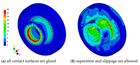
Figure 6.
Stress distribution of flange joints with different contact conditions.
In the engineering theoretical calculation of keys, two failure modes due to shear stress and compressive stress on the outer surface are analysed, as shown in Figure 7 [35]. To evaluate them from results of CAE, an understanding of stress components, first mentioned in Section 2.4.7, is necessary. Students needed to evaluate shear stress τyz for shear failure and σz for compressive failure in the case shown in Figure 8a,b. A denser mesh was created beforehand at locations where complex stress distribution was expected to arise, such as the surfaces of the key contacting to the shaft. In addition, while the theoretical results are calculated based on an assumption that stress distribution on the potential failure plane is uniform, stress distribution obtained from CAE software is much complex because of the more realistic boundary conditions. Therefore, the approximate averaged stress was derived from the maximum and minimum stress on the intended cross-section in the present workshop, and it was not so different from the theory. It was useful to train students using a practical design where some discretion is given for engineers.
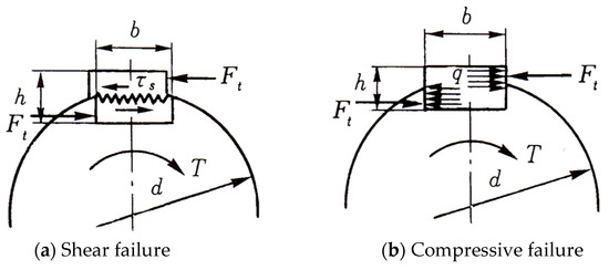
Figure 7.
Two failure modes considered in the design of keys.
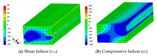
Figure 8.
Stress distribution related to evaluation of two failure modes.
2.6. Mechanical Design Project
A mechanical design project, in which students create their own design by making use of the knowledge learned from the previous lectures and workshops, was conducted as a PBL initiative. They designed structures with consideration of the strength and weight under the same design criteria given to all groups of students, and a report meeting was held after the design was completed.
2.6.1. Subject
The design of a stand frame for a slender object with skewed weight distribution was chosen as the subject. CAD data of the slender object were given to the students, and a stand frame, which is attached to the object, was designed by the students with their own ideas under following design criteria:
- The slender object is allowed to be fixed using any method and in any direction;
- The slender object must be fixed at a height of 1 m or more from the ground;
- The whole structure must be self-balancing without fixation of the feet to the ground;
- Stresses in the frame must not exceed the allowable stress of materials chosen by the students with consideration of a safety factor of 5.
Works conducted by the groups with high achievements are shown in Figure 9. The distribution of von Mises stress was used to evaluate strength of the parts made with metals. Lighter colours, such as red and yellow, mean higher stress, which should be lower than allowable stress of the chosen materials. Figure 10 shows the scores earned by the same groups.
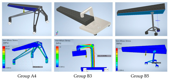
Figure 9.
Design and stress distribution of the models created in the PBL workshop.

Figure 10.
Scores earned by groups of students in the PBL workshop.
2.6.2. Groupwork
The design project was conducted by groups consisting of about six students. The members of the groups were selected by themselves for better teamwork. Teachers gave minimal supervision so that overall competency of the groups was equally distributed. Roles of the members could be divided as following examples.
- Coordination of the group;
- Construction of the model in CAD software;
- Structural analysis in CAE software;
- Preparation of presentation documents in the report meeting;
- Conducting presentation in the report meeting;
- Answering questions in the report meeting from audience.
2.6.3. Report Meeting
After all activities to design their product were completed, a meeting for students to report their works was held. All groups prepared presentation documents describing their design on Microsoft PowerPoint for the meeting. Students were advised to mention the following points in the presentation slides:
- Shape and dimension of the designed structure;
- Weight of the designed structure;
- Description of boundary conditions for the structural analysis;
- Displacement and stress distribution;
- Graphs that plot maximum stress vs. mesh density as proof of appropriate choice of mesh density;
- Tables of reaction forces at feet on the ground as proof of self-balancing design of the frame;
- Originality and ingenuity in the design
An evaluation was conducted by all students in the course through a webpage constructed using Google forms. The works were evaluated on a five-point scale from each of following viewpoints:
- Completeness of the design;
- Originality and ingenuity of the design;
- Quality of the presentation;
- Quality of answers in the Q&A session.
3. Data Collection and Analysis
To assess the improvement of the students’ performance according to the present initiative, we tracked students’ performance on preceding mechanics of materials and CAD classes and compared them to the students’ performance in the present class. One of common goals of these subjects is to be capable of solving engineering problems, of which the mechanics of materials and CAD can be considered to represent theoretical and practical aspects. Since the Mechanics of Materials and CAD classes were taught by the same teacher as the present course, similar points regarding solving engineering problem were emphasised during the lectures and exams of these courses. Therefore, by comparing the scores of these courses, improvement of the students’ performances on solving engineering problems was able to be assessed.
For the assessment of the improvement of the students, the data were partitioned into five segments as a function of achievement of the prior two courses. Students in the first segment, i.e., the low-achievement group, had scores ranging from the 1st to 19th percentile, and students in the next segment had scores ranging from the 20th to 30th percentile. Similarly, the third and fourth segments were defined, and students in the last segment, i.e., high-achievement group, had scores that ranged from 80th to 99th percentile. Their performances were evaluated with averaged scores of members of the groups. In addition to the assessment for the students grouped by their performance, the performance of groups formed in the PBL workshop were also evaluated.
At the end of the course, a short survey for summarizing the responses from the students about the course was conducted. The following multiple-choice questions were answered by the students through Google Forms:
- Q1.
- Have your skills on mechanical design improved through this coursework?
- Q2.
- Are you willing to utilize your CAE skills in your future career?
- Q3.
- Has this coursework helped you to review your engineering knowledge?
4. Results and Discussion
4.1. Performance of the Students
The averaged scores earned by members of the groups formed in the PBL workshop are shown in Figure 11. The scores in the CAD, mechanics of materials and the present course were analysed, as mentioned in Section 3. We placed emphasis on teamwork when the groups were formed in the PBL, and the selection of the members was basically left to the students. There was a little deviation overall in the competency among the groups as a result. Groups that included students who were knowledgeable in CAD or mechanics of materials tended to perform well in the present course. However, some of the groups with students in the low-achievement group in the mechanics of materials course, such as A2 and A5, showed good performance in the present course. Figure 12a shows how students were partitioned according to the score received in the mechanics of materials 1 course and those received in the present course. It is observed that the increase in the performance in the present course shown by the students with low achievement in the mechanics of materials course is higher than that shown by the high-achievement group. This indicates that the students with low achievement in the mechanics of materials class were able to improve their ability to solve engineering problems by reviewing the knowledge-linking theory and practising through the present course. Figure 12b shows how students were partitioned according to score received in the CAD course and those received in the present course. The distribution of the performance on the present course in this figure is relatively flat. Therefore, skills for CAD operation had less correlation with the improvement in the ability for solving engineering problems than knowledge of the mechanics of materials.
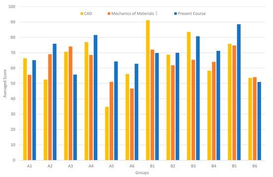
Figure 11.
Performances of groups in the design project on related courses.
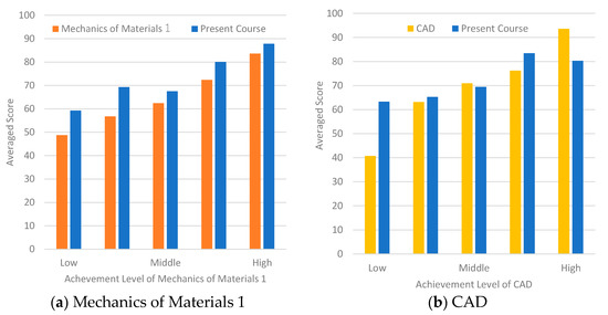
Figure 12.
Comparison of students’ performance between related courses.
Figure 13 shows a histogram of scores of the three courses. The data of the mechanics of materials course were normally distributed, although it is a little right-skewed. This means that there were more average students than students with low and high achievements. On the other hand, the data of the present course had two peaks. This indicates that a considerable number of students with low achievements moved to into the range of students with high achievements by improving in solving engineering problems through the present course.
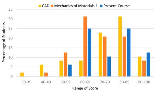
Figure 13.
Histogram of students’ performance on related courses.
4.2. Response from the Students
As mentioned in previous sections, engineering calculations with theoretical formulae were conducted in the present course to review the theory that students had already learned in preceding courses, such as the mechanics of materials. Students are often reluctant to learn topics with too great of a theoretical perspective in classes, but after the results, such as the deformation and stress distribution of analytical models, were visualised and observed in CAE software, the students could try to solve such problems without losing concentration and motivation. However, some students who did not have sufficient knowledge of engineering needed assistance in person by the teachers to solve the problems.
In groupwork, generally, students with a passive personality tended to remain spectators. In the present PBL of mechanical design, on the other hand, students tended to find their strong area that they could contribute to the team, such as modelling with CAD software, CAE structural analyses, theoretical calculations, and so on.
In the report meeting, positive opinions were exchanged between presenters and the audience, and the discussions became the basis of the evaluation of the report by the students themselves. For example, when a student was asked about the reasons for the shape of their designed structure, he described the stress distribution before and after design improvements by showing results of the stress distribution from the CAE software. This group earned the highest score for the Q&A session. Some students in other groups, on the other hand, tried to conduct presentation without sufficient understanding of the results of the analyses conducted by another member because they completely divided works to the members with lack of communication between each other. These groups received with low scores of the presentations.
The results of the short survey conducted at the end of the course are summarized in Figure 14. Results from Q1 and Q2 indicate that practical training through PBL had positive effects to improve proficiency in mechanical design with CAE. From the result of Q3, it was observed that a high percentage of students agreed that CAE structural analyses were effective for reviewing their engineering knowledge.
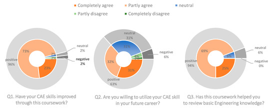
Figure 14.
Results of short survey for summarizing the course.
5. Conclusions
A course on mechanical design consisting of lectures, workshops and project-based learning utilizing CAE structural analyses was conducted in mechanical engineering department of a university. In the lectures, fundamental knowledge that links practical engineering and theoretical subjects, such as the mechanics of materials, was taught. In the workshops, CAE structural analysis was introduced to instruct students on how to use CAE software to solve engineering problems as well as to review the fundamental knowledge taught in the lectures. As for the project-based learning, a competition, in which groups of the students competed in mechanical design using their own ideas by making use of the knowledge from the lectures and workshops, was held. A short survey was conducted to review the response from the students after the course finished. Key findings from the present initiative are summarized as follows:
- -
- Practical training through the workshop problems with CAE structural analyses improved proficiency of the students in the mechanical design;
- -
- The combination of the lectures on fundamental theories and the practical workshops was effective in reviewing knowledge the students had already learned in preceding courses;
- -
- The introduction of CAE to the present course had a good effect in keeping the students motivated and concentrated on not only what they were doing the workshops but also absorbing the knowledge with a much more theoretical perspective;
- -
- Students with low achievement as well as students with high achievement on the previous theoretical course were able to improve their skills to solve engineering problems;
- -
- Many students became interested in utilizing the CAE skills obtained through this course for their future career.
The following limitations were identified throughout the course, with the intention for them to be overcome in any future activity:
- -
- Contribution to groupwork by students depending on their characteristics could not be maximized because teachers’ skill for facilitation was not sufficiently developed;
- -
- Difficulty level of the course materials was not necessarily correctly set to improve all students’ performance because of a wide range of understanding level of theoretical knowledge.
Author Contributions
Conceptualization, A.K.; methodology, A.K and H.H.; writing—original draft preparation, A.K.; writing—review and editing, H.H. and T.T.; supervision, H.H.; project administration, H.H. All authors have read and agreed to the published version of the manuscript.
Funding
This research received no external funding.
Institutional Review Board Statement
Ethical review and approval were waived for this study due to rigorous conformity with regulations of research ethics in Aichi University of Technology.
Informed Consent Statement
Informed consent was obtained from all subjects involved in the study.
Data Availability Statement
Not applicable.
Conflicts of Interest
The authors declare no conflict of interest.
References
- León, H.C.M.; Farris, J.A.; Letens, G. Improving Product Development Performance through Iteration Front-Loading. IEEE Trans. Eng. Manag. 2013, 60, 552–565. [Google Scholar] [CrossRef]
- Matta, A.K.; Raju, D.R.; Suman, K.N.S. The Integration of CAD/CAM and Rapid Prototyping in Product Development: A Review. MaterialsToday 2015, 2, 3438–3445. [Google Scholar] [CrossRef]
- Stefan, T.; Takahiro, F. The Effect of Front-Loading Problem-Solving on Product Development Performance. J. Prod. Innov. Manag. 2000, 17, 128–142. [Google Scholar]
- Meitec Inc. Survey on Introduction of 3D CAD/CAE from 500 Mechnical Engineers (in Japanese). Available online: https://engineer.fabcross.jp/archeive/200417_cad_cae.html (accessed on 22 May 2023).
- Merkel, M.; Schumacher, A. An Automated Optimization Process for a CAE Driven Product Development. J. Mech. Des. 2003, 125, 694–700. [Google Scholar] [CrossRef]
- King, G.S.; Jones, R.P.; Simner, D. A Good Practice Model for Implementation of Computer-Aided Engineering Analysis in Product Development. J. Eng. Des. 2010, 14, 315–331. [Google Scholar] [CrossRef]
- Ullah, A.M.M.S.; Harib, K.H. Tutorials for Integrating CAD/CAM in Engineering Curricula. Educ. Sci. 2018, 8, 151. [Google Scholar] [CrossRef]
- Yoichi, N.; Kazuhiro, H.; Rikunosuke, T. Education of Machine Design Using 3-D CAD/CAE (in Japanese). J. Jpn. Soc. Mech. Eng. Vol. C 2007, 73, 24–29. [Google Scholar]
- Investigating the Effect of 3D Simulation Based Learning on the Motivation and Performance of Engineering Students. J. Eng. Edu. 2013, 99, 237–251.
- Farrow, J.M.; Kavanagh, S.S.; Samudra, P. Exploring Relationships between Professional Development and Teachers’ Enactments of Project-Based Learning. Educ. Sci. 2022, 12, 282. [Google Scholar] [CrossRef]
- Juebei, C.; Anette, K.; Xiangyun, D. Forms of Implementation and Challenges of PBL in Engineering Education: A review of literature. Euro. J. Eng. Educ. 2021, 46, 90–115. [Google Scholar]
- Phyllis, P.B.; Elliot, S.; Ronald, W.M.; Joseph, S.K.; Mark, G.; Annemarie, P. Motivating Project-Based Learning: Sustaining the Doing, Supporting the Learning. Educ. Psychol. 1991, 26, 369–398. [Google Scholar]
- Brigid, J.S.B. Doing With Understanding: Lessons From Research on Problem- and Project-Based Learning. J. Learn. Sci. 1998, 7, 271–331. [Google Scholar]
- Tamim, S.R.; Grant, M.M. Definitions and Uses: Case Study of Teachers Implementing Project-Based Learning. Interdiscip. J. Probl. Based Learn. 2013, 7, 3. [Google Scholar] [CrossRef]
- Mihic, M.; Zavrski, I. Professors’ and Students’ Perception of the Advantages and Disadvantages of Project Based Learning. Int. J. Eng. Educ. 2017, 33, 1737–1750. [Google Scholar]
- Grossman, P.; Dean, C.G.P.; Kavanagh, S.S.; Herrmann, Z. Preparing Teachers for Project-Based Teaching. Phi Delta Kappan 2019, 100, 43–48. [Google Scholar] [CrossRef]
- Leggett, G.; Harrington, I. The Impact of Project Based Learning (PBL) on Students from Low Socio Economic Statuses: A Review. Int. J. Incl. Educ. 2019, 25, 1270–1286. [Google Scholar] [CrossRef]
- Pål, E.; Tonholm, T.; Johansen, F.R.; Andersson, G. Learning from Problem-Based Projects in Cross-Disciplinary Student Teams. Educ. Sci. 2021, 11, 259. [Google Scholar]
- Jonassen, D.J.; Johannes, S.; Chwee, B.L. Everyday Problem Solving in Engineering: Lessons for Engineering Educators. Res. J. Eng. Educ. 2006, 95, 139–151. [Google Scholar] [CrossRef]
- Frank, M.; Lavy, I.; Elata, D. Implementing the Project-Based Learning Approach in an Academic Engineering Course. Int. J. Technol. Des. Educ. 2003, 13, 273–288. [Google Scholar] [CrossRef]
- Perrenet, J.C.; Bouhuijs, P.A.J.; Smits, J.G.M.M. The Suitability of Problem-Based Learning for Engineering Education: Theory and Practice. Teach. High. Educ. 2020, 5, 345–358. [Google Scholar] [CrossRef]
- Udaya, K.; Randolph, C.K.L. Remodeling an Engineering Design Subject to enhance students’ learning outcomes. Int. J. Technol. Des. Educ. 2020, 30, 799–814. [Google Scholar]
- Giovanni, B.; Pietro, B.; Luca, L. Project-Based Learning of Advanced CAD/CAE tools in Engineering Education. Int. J. Interact. Manufac. 2020, 14, 1071–1083. [Google Scholar]
- Fernandes, F.A.O.; Fuchter Júnior, N.; Daleffe, A.; Fritzen, D.; Alves de Sousa, R.J. Integrating CAD/CAE/CAM in Engineering Curricula: A Project-Based Learning Approach. Educ. Sci. 2020, 10, 125. [Google Scholar] [CrossRef]
- Alejandro, G.C.; Vázquez, C.R.; Gutiérrez, M.N. Developing Competencies in a Mechanism Course Using a Project-Based Learning Methodology in a Multidisciplinary Environment. Educ. Sci. 2022, 12, 160. [Google Scholar]
- Takeshi, T.; Toshiya, A. Application of Multi-Body Simulation Environment for Mechanism Education (in Japanese). J. Jpn. Soc. Eng. Educ. 2020, 68, 39–83. [Google Scholar]
- The International System of Units (SI), 9th ed.; The International Bureau of Weights and Measures: Sèvres, France, 2019.
- Autodesk Inc. Finite Element Analysis Software. Available online: https://www.autodesk.co.jp/solutions/finite-element-analysis (accessed on 22 May 2023).
- Zienkiewicz, O.C.; Taylor, R.L. The Finite Element Method, 4th ed.; McGraw-Hill: New York, NY, USA, 1989. [Google Scholar]
- Adams, V.; Askenazi, A. Building Better Products with Finite Element Analysis; OnWord Press: Santa Fe, NM, USA, 1999. [Google Scholar]
- Simo, J.C.; Peter, W.; Taylor, R.L. A Perturbed Lagrangian Formulation for the Finite Element Solution of Contact Problems. Comput. Methods Appl. Mech. Eng. 1985, 50, 163–180. [Google Scholar] [CrossRef]
- Peric, D.; Owen, D.R.J. Computational Model for 3-D Contact Problems with Friction Based on the Penalty Method. Int. J. Meth. Eng. 1992, 35, 1289–1309. [Google Scholar] [CrossRef]
- Shuji, T. Modern Mechanics of Materials; Ohm-sha Ltd.: Tokyo, Japan, 1970. (In Japanese) [Google Scholar]
- Sadahiko, T.; Saito, M. Fundamental Mechanical Drawing by 2D/3D-CAD Based on JIS; Power-sha Ltd.: Tokyo, Japan, 2010. (In Japanese) [Google Scholar]
- Mita, J.; Asahina, K.; Kuroda, K.; Yamaguchi, K. Machine Design; Corona-sha Ltd.: Tokyo, Japan, 2000. (In Japanese) [Google Scholar]
Disclaimer/Publisher’s Note: The statements, opinions and data contained in all publications are solely those of the individual author(s) and contributor(s) and not of MDPI and/or the editor(s). MDPI and/or the editor(s) disclaim responsibility for any injury to people or property resulting from any ideas, methods, instructions or products referred to in the content. |
© 2023 by the authors. Licensee MDPI, Basel, Switzerland. This article is an open access article distributed under the terms and conditions of the Creative Commons Attribution (CC BY) license (https://creativecommons.org/licenses/by/4.0/).