1. Introduction
In the early 1960s, Ivan Sutherland, a doctoral student at the Massachusetts Institute of Technology (MIT), developed the first interactive 2D Computer-Aided Design (CAD) software, named “Sketchpad” [
1]. Since then, many pieces of related research were carried out. These type of tools rapidly spread in the field and are currently being used in numerous commercial software packages. This evolution resulted in a great variety of digital tools that directly impacted many professional activities from engineers to designers in product development [
2,
3].
In the 1980s, commercial CAD systems were developed, such as Autodesk AutoCAD, for 2D drawing, and PTC Pro-Engineer, for 3D modelling. Currently, many other CAD systems are being widely used in engineering, design and manufacturing, including geometric modelling, structural and motion analysis, CNC (computer numerical control) machining and rapid prototyping [
4].
CAD plays an important role in engineering education since there is a significant interest in learning this technology within universities, as well as in the industry [
5]. The common interest is that education should provide base knowledge and expertise for professional activity. According to Ye et al. [
6], this is only possible if four requirements are met: the capability to formulate engineering problems; the ability to use a computer in solving engineering problems; solid knowledge about the design and manufacturing processes; and most importantly, practice.
Nowadays, teachers who often deal with CAD software and teach 3D modelling in universities face a problem: the heterogeneity of the class, related to the knowledge of resources and software applications. It is common to have students in the class with solid knowledge and experience in the field, as they work daily with CAD in the development of projects. On the other hand, most students have or have had no contact with such resources. Furthermore, currently, it should be considered that basing classes only on tutorials and the sequential use of resources is not so different from ready-made content on the Internet, since countless websites, blogs, virtual forums and social networks provide the same information, without need for a teacher [
7]. As an example to this dilemma, Fritzen and Castelan [
8] addressed the application of contextualised CAD/CAM software classes to traditional manufacturing processes in the mechanical industry, presenting the computational resources applied directly to the needs of industrial projects.
In a recent work, Ullah and Harib [
9] addressed the issue of educating engineering students with knowledge of and skills in CAD/CAM. However, to solve engineering problems, especially in the field of Mechanical Engineering, knowledge of and skills in CAD/CAM/CAE are of utmost importance. Bravo et al. [
10] indicated the importance of such methodology, which gives more responsibility to the students, allowing them to participate more and thus an opportunity to develop creative skills in the area of design and manufacturing engineering.
The fact is that teaching and learning in CAD is not an easy task, as it is not just about computational skills but also the capacity to think about the problem and to solve it, as well as other important factors such as spatial vision and motor coordination. This means that less experienced students or even beginners may face some significant difficulties due to the lack of scientific basis, the need for continuous improvement and rapid obsolescence of acquired knowledge [
11]. In both cases—students with and without experience in CAD—there is a need for more theoretical bases and confidence in the use of simulation tools. Knowledge of fundamental concepts such as spatial geometry, static and resistance of materials is extremely important in the student success in order to achieve the corresponding discipline objectives.
Nowadays, with the currently available technology, it is tempting to avoid the slow, laborious and error-prone analytical calculations and go straight to the computational simulation, usually a faster solution. However, this practice is inadvisable since accurate modelling, from the input data (geometry, material definition, boundary conditions) to necessary simplifications (e.g., symmetries), is fundamental to obtain a reliable solution. Nevertheless, with the rapid development of complex numerical models applied to manufacturing, cultivating students’ ability to solve complex engineering problems using the FE method and other numerical calculations becomes more challenging [
12,
13,
14].
Recently, Guo et al. [
12] carried out a project for undergraduate students, where they implemented finite element modelling to enhance students’ understanding of theoretical mechanics and to introduce computational methods to undergraduate students at an early stage during their undergraduate education. The students were required to use different methods to analyse the stress state of a typical engineering structure and seek the optimal design (e.g., theoretical calculations). They reported a good feedback from the students, demonstrating how it can increase their interest in learning and applying the acquired knowledge.
Similarly, in this work, it is addressed how important it is to have an engineering background in order to transmit to students the application of FE analysis (FEA) in engineering problems, introducing the engineering reality into the teaching of FEA as stressed out by Guo et al. [
12]. In addition, analytical methods make it possible for the student to have a clear understanding of the physical phenomenon, gaining competences in both input data and model definition as well as in the interpretation of the results. The solving of the problem is carried by the computer; therefore, a proper definition is of outermost importance. Project errors at this level are of the responsibility of the engineer or designer. Even considering the reliability of computational systems, the model has to be configured correctly, and the professional experience of the user in the issues relevant to the simulated problem is an important resource to be considered. For instance, the constitutive models in commercial codes offer standardised options, not taking into account phenomena such as oxidation. On the other hand, complex problems where millions of finite elements are necessary are obviously unfeasible to be solved analytically. Therefore, a combination of different types of knowledge is necessary, where experience reveals to be a major variable.
Finally, analytical methods develop students’ capacity to think and criticise, to support the scientific results and to compare and question the validity of the results from numerical simulations. Yixian et al. [
15] indicate that using CAE tools in the classroom can help the student understand advanced processes regarding design, simulation and manufacturing, from a concept. The theoretical knowledge of related concepts makes it possible to easily and quickly understand it.
2. Methods
Classes were planned by establishing and prioritising a connection between CAD and CAE tools. Nevertheless, in the first place, the analytical solution is explored and only then the numerical one. The teaching plan was structured in twenty weeks (face to face meetings). They took place at the laboratory of computational mechanics used in the teaching of 3D modelling, structural simulation and also in the simulation of manufacturing processes. The development of this curricular component is related to Computer-Aided Design and Manufacture, which occurs in the seventh semester of Mechanical Engineering Course, offered by Faculty SATC, from Criciúma, Santa Catarina State, Brazil.
The first four meetings are intended for the presentation and development of activities related to visualisation and transformations, which are responsible for the generation and manipulation of the three-dimensional parts generated on the computer screen. The fifth and sixth meetings are intended for presentation of the modelling features. In this step, there is no use of tutorials and learning takes place via intuitive use of basic commands, easy to assimilate.
The next eight meetings are intended for modelling and structural validation of solids (parts and products), through analytical (manual calculations) and numerical calculations (computer simulation). The following two meetings are dedicated to mould generation procedures and manufacturing simulation (machining). Finally, this cycle ends with the elaboration of a collaborative project carried out by teams during the remaining four meetings. This project addresses all content explored in the course, including modelling, selection and definition of material, structural validation, simulation, tooling creation (mould/die), machining simulation and drafting of technical documentation (e.g., drawings). Thus, the amount of content is extensive considering the course load of 60 h, demanding the collaboration and commitment of both teacher and class to achieve the goals set in due time.
Analytical-Numerical Methodologies in the Classroom
This section presents a problem solved in the classroom during the course of Computer-Aided Design and Manufacturing within the curricula of Mechanical Engineering. The content of this class is based on geometrical and numerical modelling and also analysis of static loading. It is expected that students already have knowledge regarding technical drawing, structural loading, mechanical resistance and basic experience with CAD tools.
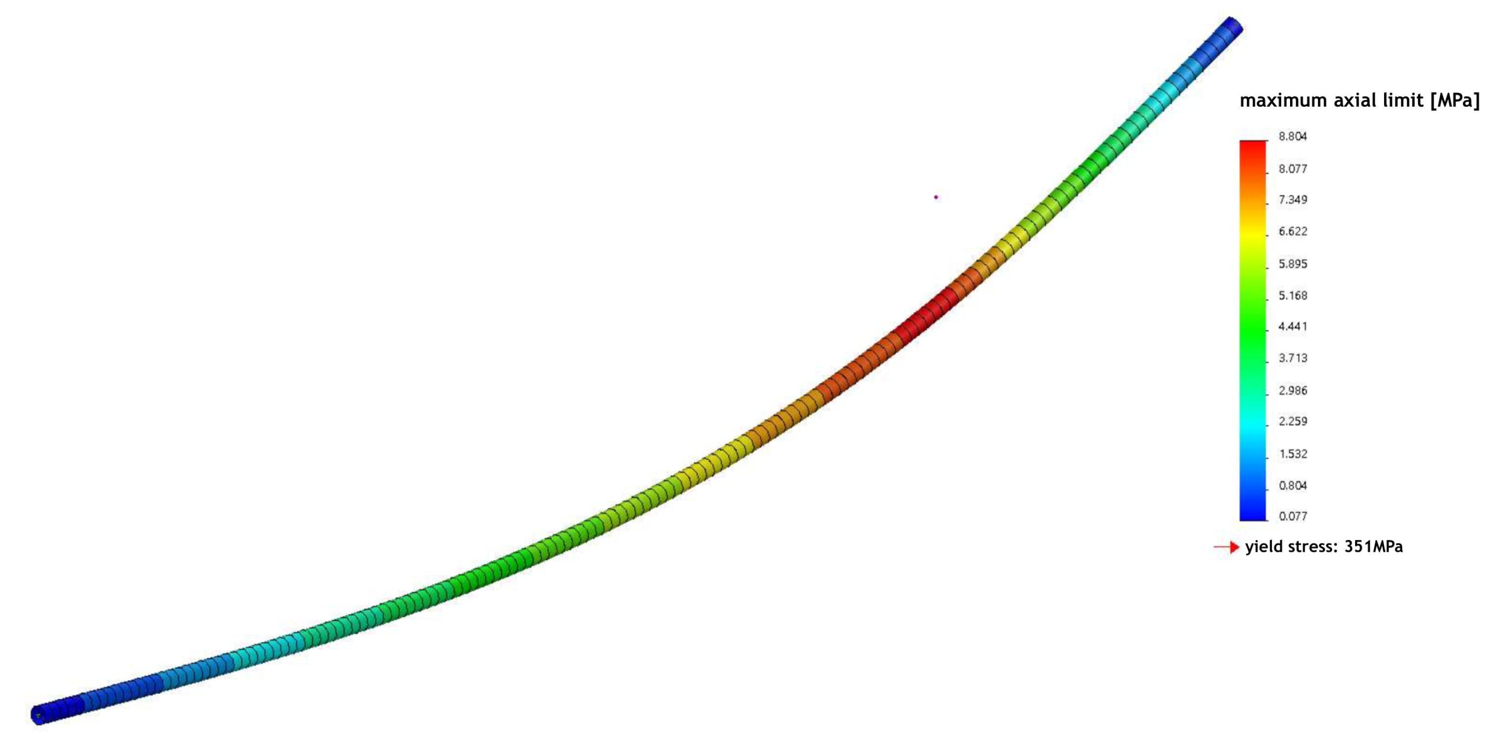
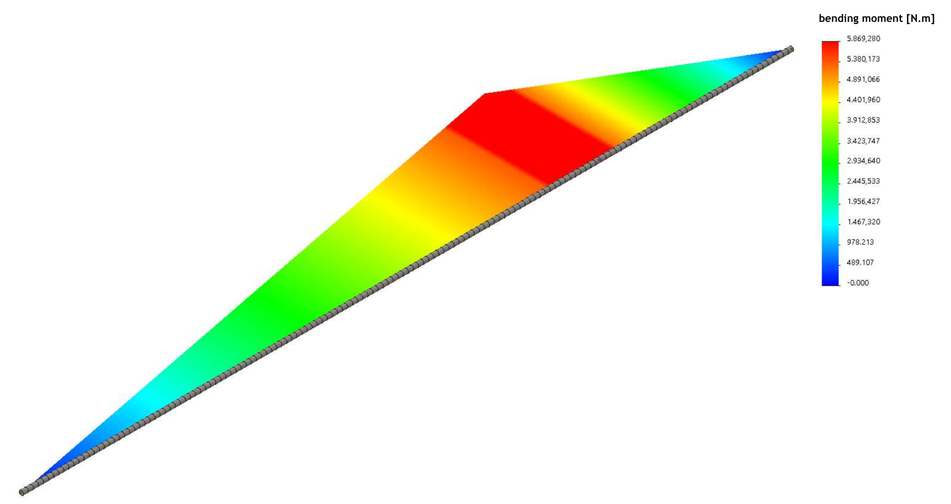
In this activity, it is expected that the student is able to interpret and analyse the problem, to model it using CAD tools and to simulate it. The problem consists in determining if a beam has enough strength to support a concentrated static load.
Table 1 summarises the different steps planned for the student to solve the structural problem. The factor of safety expresses the load carrying capacity of a system beyond what it can actually support, basically, how much stronger it is than it needs to be for specific loading conditions.
Structural parts and metal profiles, such as I and U beams, are relatively easy to model. The student sketches the profile and assigns a length for extrusion. Nevertheless, due to the beam’s structural function, the simulation of working loads, both static and dynamic, is fundamental to validate a model by determining the type and size of the profile, its layout in the structure and ideal manufacturing material considering safety and financial constraints.
Figure 1 depicts the problem presented to the students.
4. Conclusions
The use of different methodologies for solving the presented structural problem makes it possible for the teacher and students to have more tools available to themselves. This increases the efficiency of the cognitive process and boosts the acquired knowledge in a sustained manner. Although each simulation software has its specific settings, the scientific base built with the analytical processes enables the student for a faster and safer adaptation in his future professional activity.
At first, an aversion of students to manual calculations and an instant desire to skip this step and go straight to computational simulation are noticeable. However, when the comparison of results is performed, the students perceive the relationship between scientific theory and the practical result presented by the numerical code. This perception makes the student realise the importance of manual techniques in the development of learning.
Both the analytical-manual and numerical-computational processes, even when performed within the correct procedures, may not indicate an absolute truth. As mentioned above, real situations present complex variables and unusual situations that calculation processes, due to their simplifications, do not consider. The development of knowledge in science involves modelling processes where theory, experiment and computation are dynamically interconnected [
17]. It is important that the teacher transmits this reality to the students. For a completely safe analysis, it is necessary to include one additional and final step—the experimental one.

 ,
, 


