Abstract
Electrical impedance tomography is a low-cost, safe, and high temporal resolution medical imaging modality which finds extensive application in real-time thoracic impedance imaging. Thoracic impedance changes can reveal important information about the physiological condition of patients’ lungs. In this way, electrical impedance tomography can be a valuable tool for monitoring patients. However, this technique is very sensitive to measurement noise or possible minor signal errors, coming from either the hardware, the electrodes, or even particular biological signals. Thus, the design of a good performance electrical impedance tomography hardware setup which properly interacts with the tissue examined is both an essential and a challenging concept. In this paper, we adopt an extensive simulation approach, which combines the system’s analogue and digital hardware, along with equivalent circuits of 3D finite element models that represent thoracic cavities. Each thoracic finite element model is created in MATLAB based on existing CT images, while the tissues’ conductivity and permittivity values for a selected frequency are acquired from a database using Python. The model is transferred to a multiport RLC network, embedded in the system’s hardware which is simulated at LT SPICE. The voltage output data are transferred to MATLAB where the electrical impedance tomography signal sampling and digital processing is also simulated. Finally, image reconstructions are performed in MATLAB, using the EIDORS library tool and considering the signal noise levels and different electrode and signal sampling configurations (ADC bits, sampling frequency, number of taps).
1. Introduction
Electrical impedance tomography (EIT) is a low-cost imaging technique which applies a 1 kHz–1 MHz frequency low amplitude electrical current to a subject under test (SUT) and collects the measured voltages from an electrode cluster [1,2]. Then, an estimation of the SUT internal conductivity distribution is performed through a set of inverse algorithms [3]. Although EIT is characterized by critically low spatial resolution compared to X-ray, CT, and MRI, it has the advantages of the absence of ionizing radiation, patient safety, low hardware cost (20 to 100 times compared to a CT scanner), and high speed. High frame rates lead to significant temporal resolution, which makes EIT suitable for applications that need real-time monitoring, such as thoracic and ventilation imaging [3,4,5].
EIT’s spatial resolution, however, might be further limited by signal noise, since the EIT inverse problem is ill-posed and ill-conditioned [6]. Image artefacts that appear are also related to common signal effects, usually caused from mismatches in the current source and between the electrode channels, combined with limited common mode rejection ratio (CMRR) at the voltage recording circuitry [5,7]. In addition, signal degradation due to the channels’ or IC’s stray capacitances is a factor that reduces the image quality, especially at frequencies above 100 kHz.
In the case of real-time (dynamic) thoracic imaging, these effects are more intense, since higher signal frequencies are required to achieve a sufficient frame rate and thus temporal resolution in order to extract useful clinical information related to the patient’s lung functionality. We note that for perfusion (cardiac-related impedance changes) imaging, even higher frequencies and voltage levels are essential [8,9]. Furthermore, the effect of thoracic boundary change during each breath cycle, as well as the fact that the accurate boundary shape is unknown, leads to the presence of artefacts. Two related studies demonstrated that a mismatch of more than between the actual thoracic boundary shape and the EIT reconstruction domain boundary has major effect in the image quality [10,11].
Considering the many possible sources of imaging errors, the design and implementation of a good performance EIT hardware which is capable of high signal quality excitation is the first essential step for successful EIT imaging. Many different EIT systems have been implemented over time, both generic and application-targeted. Such general purpose EIT systems are the Sheffield MK (v1 1987, v3.5 20021) [12], the ACT 3 and ACT 4 EIT systems [13,14], and the KHU Mark 2.5 system (2014) [15]. In addition, some EIT systems have been developed specifically for dynamic thoracic imaging, such as the Swisstom AG (2012), the ACE1 [16], and the systems presented in [4,17]. These EIT systems make use of active electrodes [18,19] in order to reduce the effect of stray capacitances. Although there has been such improvement in the performance of EIT systems during the last decade, their design and implementation still remains a challenging concept and an open research topic.
Some research has been performed on how to set the proper requirements and design an EIT system. Ref. [20] performs an analysis for the voltage acquisition part of custom EIT systems, deriving a specific model to calculate it. Ref. [21] presents a structured design methodology to achieve a high in EIT systems, focusing on the choice of the instrumentation amplifier at the voltage acquisition part and the analogue-to-digital converter’s (ADC) specifications. Similar analysis has been performed in [22], where a low-power readout front-end is also designed, and in [4,17,23], with integrated circuit designs.
Although research has been done in system design optimization, it mainly focuses on noise compensation. However, the design of an EIT system faces many other challenges, such as common signal effects due to contact impedances and parasitic effects [5]. Hence, a simulation approach which includes these effects could actually assist in examining their possible impact in imaging quality.
Simulation approaches to EIT hardware and impedance modelling have already been presented. In [24], a general 2D SPICE multiresolution impedance method for low frequencies is presented, where a resistor network mesh is created. In [25], a MATLAB interface which transfers a finite element (F.E.) mesh with assigned impedance or conductivity values to each element to a resistive multiport equivalent was presented. This interface is part of the EIDORS library tool, which is commonly used for EIT image reconstructions [26]. A preliminary integration of 2D F.E. mesh circuit equivalents to basic EIT circuitry for SPICE simulation and image reconstruction was presented in [27], where the impact of electrode short-circuit or disconnection was simulated. This approach was extended in [28] where simulations on 3D saline tank equivalents were performed under single ended and mirrored Howland current pumps. The DAC and ADC functions were also simulated in MATLAB, and results were acquired and compared for 2 current signal frequencies and 2 ADC sampling rates. A minor extension was presented in [29], where the thermal, flicker, and quantization signal noise effects, as well as the demodulation part, were added to the previous interface.
In this paper, the SPICE-MATLAB EIT simulation interface described in [28,29] is applied to three-dimensional thoracic structures. In specific, two fine F.E. thoracic structures are extracted, based on CT images and representing the deflated (full-exhalation) and inflated (full-inhalation) states respectively. Each tissue’s relative conductivity and permittivity are loaded from a web database using Python, according to the current signal selected frequency. Both structures are transferred to 16-port RLC networks and added in the SPICE EIT circuitry for transient simulations, resulting in two corresponding measurement frames. Signal noise is included, and the sampling and digital processing are simulated in MATLAB, in order to acquire the expected image reconstructions. Simulations are carried out assuming 2 electrode sizes and various ADC specifications and number of taps per voltage channel measurement. It is noted that instead of the previously presented interface which uses only resistive equivalent networks, in this work, both SUT conductivity and permittivity are considered, leading to a frequency-dependent RLC multiport equivalent network. Thus, a standard in-phase and quadrature (IQ) demodulation technique is also simulated in MATLAB. Finally, qualitative and quantitative evaluation of the reconstructed images is performed in order to compare the corresponding image results of each simulated configuration.
The remainder of this paper is written as follows. In Section 2, the EIT measurement principle is briefly described. In Section 3, the thoracic structures evaluated in this study as well as the tissues admittance data are presented. Section 4 synopsizes the SPICE-MATLAB interface used for the simulations. Furthermore, in Section 5, the reconstruction domain used, the algorithm with its parameters, and the image evaluation method are described. In Section 6, the hardware and electrode configurations are presented, while presentation and comparison of the results are performed. Finally, Section 7 concludes this paper.
2. EIT Principle
In EIT, a low or medium frequency AC current (usually up to 1 MHz, depending on the application) of a small amplitude (up to ) is injected to the SUT through 2 selected electrodes from an electrode array attached on its surface. At the same time, differential voltages are acquired through other electrode pairs, rendering a set of tetrapolar measurements. The process is repeated for a number of current electrode pairs. The final set of tetrapolar measurements acquired consists of a measurement frame . In time-difference EIT (td-EIT) imaging, which is usually used for real-time thoracic imaging, two measurement frames are needed to reconstruct an image. Their difference is used as data in the reconstruction algorithm.
Although many measurement patterns have been used in EIT, the most commonly utilized in lung imaging is the adjacent pattern [30,31]. It is characterized by the current excitation of two neighbouring electrodes and voltage measurement between two other neighbouring electrodes at each time [32]. Although the adjacent pattern presents low field sensitivity to the current injected near the centre of the SUT, it is often preferred due to the fact that it offers more independent measurements compared to other patterns [32,33]. In terms of this work, we make use of the adjacent current pattern. However, the simulation interface can be easily modified in order to include other measurement patterns (as in [29], where the skip-3 current pattern is also activated [34]).
The basic EIT circuitry consists of a voltage controlled current source (VCCS) of sufficient transconductance and large output impedance in the largest possible frequency range [5,35]. The signal waveform (usually sinusoidal, but sometimes pulse signal as superposition of multifrequency signals is used) can be digitally produced from a digital-to-analogue converter (DAC), controlled by a direct digital synthesizer (DDS). The voltages are acquired by an analogue front-end (AFE) which usually includes one or more instrumentation amplifiers (IA), filters, programmable gain amplifiers (PGA), and an ADC driver [1,5,21]. Both the current source and the voltage recording parts are connected through switching multiplexers to an electrode array which is attached on the SUT surface. The analogue voltages are sampled from an ADC (usually successive-approximation, SAR), and the samples are sent to a processing unit (MCU, DSP, or FPGA), which performs the synchronization with the input signal, the demodulation, and the switch control. Finally, the processed measurements are sent to a PC for the image reconstruction. A brief schematic of the description above is presented in Figure 1. It is noted that this is a basic EIT configuration principle and not necessarily the unique or optimal one. For example, some systems use active electrodes [4,17], placing the multiplexers before the VCCS (current source) and after the first IA. Other systems drive multiple electrode pairs with more than one current frequency [36] (these systems apply frequency-difference EIT usually used in brain imaging applications). Moreover, some systems perform simultaneous measurements at the voltage recording front-end [16], while many systems enact analogue demodulation before the ADC part [37,38].
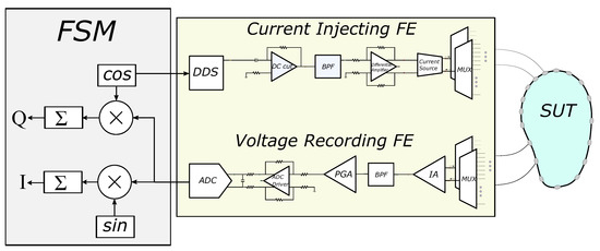
Figure 1.
Basic EIT hardware concept. The SUT, current injecting front-end (FE), voltage recording FE, and the finite state machine (FSM) are included.
3. Thoracic Structures
The thoracic SUT was simulated by implementing two fine (dense) 3D F.E. models, representing the full-exhalation (deflated) and the full-inhalation (inflated) lung states respectively (Figure 2). Both models were implemented in MATLAB using the NETGEN tool [39]. Each model includes the following tissues: left lung, right lung, heart, vertebra, skin, and the (muscle-plasma) background. Each tissue’s conductivity and permittivity were loaded from a database demonstrated in [40,41,42], according to the current signal frequency selection (i.e., the frequency of the current signal produced from the VCCS). The corresponding conductivities and permittivities per frequency between 1 kHz and 1 MHz are demonstrated in Figure 3. In this particular work, we have examined measurement (current signal) frequencies of 15 kHz (low frequency case) and 100 kHz (medium frequency case). For each one of these two frequencies, we assigned the corresponding and values to each 3D F.E. model’s element, according to which one of the mentioned tissues corresponds. To take into consideration possible inhomogeneity in each particular tissue, a standard deviation () of for the muscle-plasma background and the heart, for the lungs, and for the skin and bones were assumed. The nominal values assigned to each tissue along with the are shown in Table 1.
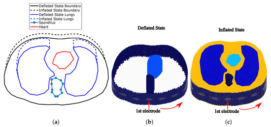
Figure 2.
(a) Cross-section of the F.E. thoracic model boundaries and tissues simulated for the
deflated and inflated states. (The deflated state is based on an adult male CT image.) (b) Fine thoracic
F.E. model for the deflated case (the lungs are not visible since their conductivity is similar to the
background’s one). (c) Fine thoracic F.E. model for the inflated case. The lungs’ conductivity is
significantly lower than the background’s one. In both (b,c) cases, the skin has been included.
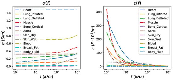
Figure 3.
Left: Relative conductivity per thoracic tissue in the frequency range between 1 kHz and 1 MHz. Right: Relative permittivity per thoracic tissue in the frequency range between 1 kHz and 1 MHz.

Table 1.
Assigned conductivity and permittivity values to the thoracic models’ tissues for kHz and kHz. The admittance is estimated as . For the skin and fat case, the average values of wet skin and breast fat admittances (see Figure 3) were used.
The deflated (i.e., state where the lungs are empty) 3D F.E. model’s geometry and tissues’ boundaries have been taken from a CT-scan of a healthy adult male at the 4th intercostal muscle height. The CT boundary and the corresponding 3D model are available online in the EIDORS library tool [26]. The F.E. model uses this geometry as a cross-section to create a 3D fine structure, with the x-axis normalized between and 1, and the height set to 1.
For the inflated 3D F.E. thoracic model (i.e., state where the lungs are air-filled), we assumed a chest boundary movement of and a lung cross-section area increase of (see Figure 2a)). These values fall into the ranges described in [43]. The 3D F.E. model was created accordingly, as shown in Figure 2c). In both models, we have assumed two different electrode placements. In the first, electrodes were accurately placed on the 4th intercostal height (i.e., in the middle of each F.E. model’s total height, ). In the second one, an electrode position error has been added, assuming that the electrodes present a height and a angle std around their nominal values used in the first configuration. Furthermore, for both placements, circular electrodes of radius 0.05 (arbitrary unit—AU) and 0.03 AU are considered. These configurations were added in order to examine the effect of electrodes’ placement error and their size in the signal and the reconstructed images’ quality. The numbers of nodes and elements per model and electrode configuration are shown in Table 2.

Table 2.
Number of tetrahedral elements and nodes of each 3D model case.
4. Simulation Interface
In this section, we briefly describe the simulation approach used for this work. The interface used includes a MATLAB part which creates (with the assistance of NETGEN) the 3D models and assigns the tissue admittance values, loaded via Python from the database [41] to each element. MATLAB also uses the EIDORS library tool [26] with minor modifications to transfer the 3D thoracic models to RLC 16-port equivalent networks. These networks are integrated in LT SPICE with the whole EIT analogue circuitry, where transient simulations are executed. The transient measurements are imported in MATLAB, where the expected white noise is added and sampling and digital processing are simulated. From the final measurements acquired, the image reconstruction process is performed with the EIDORS tool. The overall process is described in [28,29]; however, for clarification, we synopsize the main parts. Furthermore, emphasis is given in the active electrode configuration, which was not simulated in previous works.
4.1. F.E.M. to RLC Equivalent Circuit Transformation
Considering the 3D thoracic F.E. model, we obtain the following system equation:
where are the nodal potentials for the corresponding model, is the element-assembled matrix, and express the complete electrode model (CEM) boundary conditions [44], and refers to the nodes where the measurements are taken [45]. Furthermore, is the voltage measurement vector, and is the current injected per electrode. By writing , it can be proved that [25,28]
By setting , we obtain a sparse, almost symmetric conductivity (or admittance) matrix. Therefore, the impedance between two nodes i and j (where voltage measurements are taken) is computed as [25,28,46]
In the case where admittances are considered, . Thus, each impedance can be implemented by a parallel combination of a resistor and either a capacitor or an inductor. In this way, we compose an RLC equivalent circuit, where each terminal corresponds to an EIT electrode.
4.2. EIT SPICE Circuitry
The SPICE EIT circuitry used for the simulations is mainly based on the basic structure presented in Section 2. It is implemented according to the passive electrode configuration (i.e., the analogue circuitry is connected to the electrode channels via cables and switches with parasitic capacitors) and the partially active electrode configuration (i.e., the first voltage readout stage—usually a buffer—is placed on each particular electrode, significantly reducing the parasitic effects).
The input signal is created in MATLAB in discretized (vector) form, demonstrating a -bit DAC look-up-table (LUT) [28]. LUTs for 15 kHz and 100 kHz sinusoidal waveforms are considered, while the DAC sampling rate is simulated at 16 times higher than the corresponding input signal’s frequency. Each input waveform is stored in a PWL file, which is transferred to LT SPICE. In addition, the multiplexer digital inputs, according to the measurement pattern adopted, are also stored in PWL files, read by LT SPICE.
The analogue SPICE circuitry current injecting front-end consists of a second-order multiple feedback wideband band pass filter (BPF), a fully differential voltage output driver (THS413-Texas Instruments), and an enhanced mirrored Howland current pump (HPC) which acts as a VCCS. The voltage recording front-end is implemented as a partially active electrode, exclusively in the 100 kHz input signal case, and as a typical passive electrode for both the 15 kHz and 100 kHz input signal cases. In the active electrode configuration, each electrode is directly connected to a buffer (which is placed very close to the electrode). Then, each buffer’s output is connected to the IA through analogue (bi-directional) multiplexer switches (ADG426 analogue devices) and two first-order high-pass filters (one per IA input channel). In the passive electrode configuration, each electrode is directly connected to two ADG426 analogue multiplexers, one for each differential measurement channel. Each ADG426 output is connected to a buffer and each buffer’s output is driven to the corresponding input of the AD8421 IA through a first-order high-pass filter. The mirrored HPC VCCS is connected to the electrodes through two ADG426 multiplexers (one for the source and one for the sink electrode) in both the active and passive electrode configurations. The multiplexer switches on resistors are included in the ADG426 SPICE model, while parasitic capacitances (randomly chosen in the range of 100–200 pF) between the electrode channels have been manually added in SPICE, in order to simulate parasitic effects. Furthermore, to include channel imbalance effects at the output (i.e., common signal effects), unequal resistors (20–60 ) have been introduced to each measurement channel. Finally, the electrodes are modelled as in [28], according to the descriptions in [47,48,49] (assuming AgCl electrodes). A brief schematic of both configurations, including the parasitic effects and channel impedances, is presented in Figure 4.
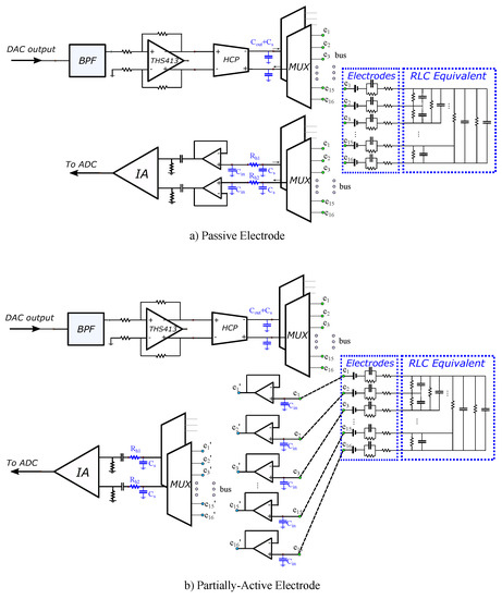
Figure 4.
LT SPICE analogue circuitry configurations for (a) passive electrodes (cables and switches between the readout front-end circuit and the electrode) and (b) partially active electrodes (the first stage of the readout circuit is implemented directly on each particular electrode). Blue-coloured components indicate the parasitic capacitors and channel resistors added to simulate their effect.
4.3. Sampling and Digital Signal Processing
A transient simulation is performed in LT SPICE for each image frame. Its total duration depends on the input signal’s frequency as well as the selected time between two particular differential voltage measurements. The simulation stops when all the measurements defined by the selected pattern (adjacent) have been acquired. The transient results are written on a text file and sent to MATLAB for processing. The input reference signal is also measured from an IA and sent to MATLAB, in order to sample it and demodulate it with the output signal. Finally, a noise simulation at the SPICE circuit produces a power spectral density diagram (PSD). The total amount of noise, resulting from the integration of PSD, is added to the IA signal output in MATLAB [29].
A MATLAB software program simulates the ADC function in the following way. First, the number of bits and the sampling frequency are selected. Assuming negligible conversion times, the time points where the signal must be sampled are defined for each measurement window (time space between two switch changes) [28]. Then, for each defined time point, the nearest corresponding SPICE time value is found and the corresponding transient voltage value is sampled (note that the longest timestep in LT SPICE simulations is set to 100 ns, many times smaller than the ADC sampling period which is 625 ns at maximum). The sampling process is explained in detail in [28].
The sampled values from the input and output signals are stored in binary form (dropping the two LSBs which are assumed as noisy), and IQ demodulation is performed (see Figure 1). The multiplication results are driven to an adder, which actually acts as a digital low pass filter (LPF). From the in-phase and quadrature results, the signal amplitude of each measurement window is estimated. The final set of amplitudes is then used as data for the difference image reconstruction.
The whole simulation interface is shown in Figure 5. It includes the MATLAB/NETGEN modelling interface, where the tissues’ electrical properties are loaded from the mentioned database to the two 3D simulation structures (deflated and inflated). These structures are transformed to an RLC equivalent circuit, which is simulated at LT SPICE, along with the whole analogue EIT circuitry, which is shown in a “white box”. Any noise, parasitic effects, channel mismatches, and components’ non-idealities are added in the SPICE circuitry. The SPICE transient measurements are transferred in MATLAB to be processed as described before, and the reconstruction is performed with the EIDORS tool.
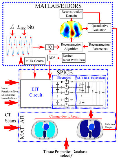
Figure 5.
Brief diagram of the proposed thoracic EIT simulation interface.
It is important to note that both the simulated analogue circuitry and the digital part are not optimal and are not necessarily recommended for novel EIT system designs, since this is beyond the scope of this work. Instead, the simulations presented compare the expected performance of state-of-the-art EIT hardware designs at different configurations in lung imaging. However, the simulation interface proposed can be easily modified to simulate the performance of new hardware designs.
5. Reconstruction and Evaluation Method
In this section, a description of the image reconstruction approach is written, presenting the selected algorithm and its parameters. Furthermore, a method for quantitative evaluation of the produced images is presented, in order to perform a more considered comparison.
5.1. Image Reconstruction
Assume that is the difference voltage data, acquired from two continuous measurement frames (e.g., from a thoracic deflated and inflated state, respectively). We also assume a 2D EIT coarse-element reconstruction domain , consisting of triangular elements. This domain’s elliptic boundary differs from the 3D thoracic F.E. (both deflated and inflated states) boundaries since (A) the SUT boundary is not accurately known in real EIT lung imaging applications, and (B) to obtain a robust reconstruction result, we need to avoid the well-known inverse crime [6]. Then, the conventional difference-EIT reconstruction is considered as an optimization problem, where we have to find the optimal (admittance change) distribution that minimizes the following quantity [50]:
where
In the expression above, and are the simulated electrode voltage vectors at the two states (assuming admittance distributions and in , respectively), is a weighting matrix, is the regularization hyperparameter, and is the regularization term [1,3,50]. We note that regularization is essential, since the EIT reconstruction problem is both ill-posed and ill-conditioned [1,6]. It is also a heavily non-linear problem.
For this particular work, we use the linearized difference-EIT reconstruction with a smooth regularization term. This is the most common approach in dynamic thoracic imaging, since it enacts only one reconstruction step, allowing real-time imaging. However, it often suffers from accuracy, since the admittance changes during the breath cycle are usually significant [43]. The linearized difference-EIT reconstruction assumes small admittance changes near ; hence, , where
is the Jacobian matrix. The optimization problem (4)–(5) then becomes
where is the prior regularization matrix [50]. We enact generalized Tikhonov regularization, obtaining the following single-step solution [3,50]:
In terms of this work, the Laplace smoothness prior is used for the reconstruction [50]. However, other priors, such as the NOSER, standard Tikhnonov, or Gaussian could be also used to obtain the EIT images without loss of generality. The hyperparameter has been heuristically selected to for all the cases. We note that the selection of single-step generalized Tikhonov regularization is indicative, and more recent approaches, such as learning approaches [51,52,53], could also be applied and can be considered for future work.
The reconstruction domain is a triangular element 2D thoracic shape mesh, shown in Figure 6a. The gap electrode model has been applied in this domain to model the electrodes [54,55]. Shape mismatch between the true (cross-section 3D) boundary and the reconstruction domain’s boundary (, Figure 6b) introduces a minor modelling error. However, the exact thoracic shape is never accurately known, and it also changes during the breath cycle [4,11].
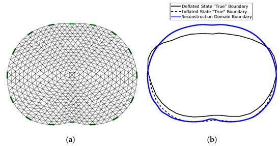
Figure 6.
(a) 2D reconstruction thoracic domain (Ω). (b) Shape mismatch between the “true” cross-section model and Ω.
5.2. Image Evaluation Method
To evaluate the reconstructed images, we have to set a reference image for the comparisons on the same domain . , however, differs from both the 3D models’ boundary shapes. As a result, it is necessary to primarily set a “true boundary” 2D reference, based on the cross-section of the 3D models. At this point, we take into consideration that (A) the 3D model’s shape is not constant, and (B) we perform difference-EIT imaging; thus, we reconstruct a single EIT image which represents the conductivity (and permittivity) differences between the two states. To this end, we assume two “true boundary” cross-section 2D references, one for the deflated and one for the inflated case. Then, the domain reference image is created in the following way. First, we scale the and each “true boundary” domain in the y-axis, matching them as shown in Figure 6b. Their horizontal limits are also normalized between and 1. Secondly, we assume to be the domain’s ith-element area (). For each element i, we find the following weight vector:
which represents the percentage of which is included in the following corresponding six tissue curves of the deflated state “true” domain: left lung, right lung, vertebra, heart, skin, and muscle-plasma. The corresponding vector which represents the tissues’ (mean) admittances at the deflated state is defined by
Then, we compute the corresponding reference admittance as (see Figure 7a)
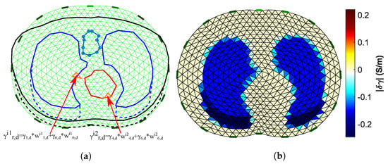
Figure 7.
(a) Visualization of the process to obtain the Ω domain reference image. (b) The Ω domain reference image (15 kHz case).
In the same way, we compute each i element’s reference admittance for the inflated state:
where
is the ith element’s weight vector at the inflated state and
the vector which represents the tissues’ (mean) admittances at the inflated state. We set the deflated and inflated state reference admittances for the domain :
The final domain reference has the following admittance difference values:
where . The reference image obtained is shown in Figure 7b.
At both the reference and the reconstructed images, the (amplitude) term is demonstrated. For the quantitative evaluation and comparisons, the correlation coefficient metric has been considered, defined as follows:
where is the ground truth admittance amplitude, is the admittance amplitude distribution estimated from the image reconstruction, and Cov is the covariance between reference and estimated values. The value of ranges between 0 and 1, and higher indicates more similarity between the reference and the reconstructed image.
In addition, to enhance the quantitative evaluation, the relative reconstruction error metric has also been used, defined as follows [52,53]:
We note that for the calculation of , both and were normalized between and 1. Higher indicates a larger error between the reference and the reconstructed image.
6. Results and Discussion
In this section, the simulation cases are firstly defined, based on the electrodes’ properties, dimensions, and deviation and the digital acquisition part’s configurations. The theoretically expected s are also computed for each ADC configuration case. In addition, the obtained images per case are presented, as well as the resulting metrics. Furthermore, both qualitative and quantitative results are discussed.
6.1. Simulation Cases
For the simulations, we consider two input sinusoidal frequencies: kHz and kHz (see Section 4.2). For the kHz case, SPICE simulations are carried out using the passive electrode configuration, while for the kHz, both passive and active electrode configurations are considered. This is because parasitic effects are much more significant at kHz than at kHz. Furthermore, for each of the previous three cases, we examine (A) accurate electrode placement on the 4th intercostal height, (B) electrode deviation ( height and angle), (C) circular electrodes of (A.U.) radius, and (D) circular electrodes of (A.U.) radius (for further details, see Section 3). Moreover, we simulate the following ADC cases: (A) resolution of bits and sampling rate of , (B) bits and sampling rate of , (C) bits and sampling rate of , and (D) bits and sampling rate of . Finally, we also consider and sine periods to be sampled per voltage channel measurement (see [29] and Figure 8). Hence, we obtain a total of 96 sub-cases for imaging, evaluation, and comparison.
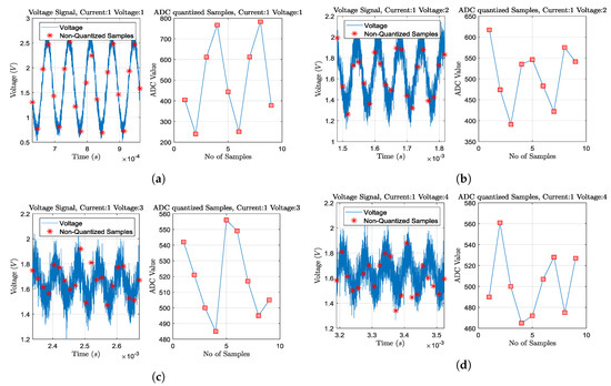
Figure 8.
Transient plus noise simulations and ADC sampling process for some particular voltage channel measurements,
when at deflated state, acting at 15 kHz, 2mAp−p current signal, and considering 0.05 radius passive electrodes without position deviation. Sampling and quantization is performed for 2 sine periods, as shown in each right part. Current is injected from the 1st and the 2nd electrodes (adjacent current protocol). The ADC resolution is considered at 12-bit (10-bit ENOB) with a 3.3 V reference voltage. (a) Adjacent voltage measuring between the 3rd and the 4th electrodes. (b) Adjacent voltage measuring between the 4th and the 5th electrodes. (c) Adjacent voltage measuring between the 5th and the 6th electrodes. (d) Adjacent voltage measuring between the 6th and the 7th electrodes. As the voltage measuring electrode pair becomes far from the current injecting pair, the noise effect becomes more significant, due to the signal’s amplitude decrease.
The expected voltage amplitude can be computed according to the following formula [20]:
where A is the mean acquired voltage signal amplitude, K the number of matched digital LPF filter taps (samples) at the IQ demodulation part, the ADC voltage reference ( V in the simulated cases), the ADC resolution (bits), and the circuit noise std. The ratio denotes the LSB voltage range. Furthermore, the number of taps per measurement is defined by . As voltage signal amplitude A, we take the mean amplitude between all the channel measurements (208 for the adjacent pattern when 16 electrodes are attached [1,56]). For the estimation, we also assume that it is not considerably affected by the electrode configurations or the patient’s state. However, if we consider different topologies than in Figure 4, possible changes in noise levels between active and passive electrode configuration should be considered (see [4]). Moreover, an increase in signal frequency has a substantial role in reduction, firstly due to the need for higher sampling frequencies and secondly due to the lower voltages acquired, resulting from the increased tissue admittances (see Figure 3 and Table 1). Therefore, we examine 16 different cases, as demonstrated in Table 3. A value of was extracted from LT SPICE noise simulations. This value strongly depends on the input current amplitude and the instrumentation amplifier’s gain (set as and 200 V/V, respectively, for these particular simulations). Table 3 shows the calculated voltage amplitude per case.

Table 3.
Calculated mean SNR values (dB) for each measuring parameter case, according to (19).
As demonstrated, the expected voltage is reduced as the input signal frequency increases from 15 kHz to 100 kHz. At the same time, increasing the sampling frequency from 4 to 16 times the signal frequency and the sampled periods from 2 to 4 (i.e., the number of taps/samples per measurement) leads to improved values. In addition, an increase in the ADC resolution did not have a noticeable effect on in the cases tested. This can be explained by observing (19) denominator term. It is demonstrated that if noise level from the analogue circuitry is significantly higher than the first term, then the ADC resolution does not have a substantial role in the SNR. Nonetheless, this noise can be filtered from the digital LPF by increasing the samples per measurement (K).
We note that these s are the mean ones per each particular measurement frame. In fact, there is a large variation between the voltage channels’ measurement s, due to the wide voltage amplitude range. For example, voltage electrode pairs close to the current electrode pair drive significantly higher voltages than the voltage electrode pairs on the other side of the setup, resulting in higher levels. It is also noted that the selected hardware circuitry, as well as the ratio between the voltages acquired and , is not optimized in this particular work. However, the simulation interface presented can be an effective tool for this direction.
6.2. Simulation Results
The images obtained for kHz and passive electrode configuration are shown in Figure 9. The corresponding and values are shown for each subcase. In almost all the images, the admittance reduction due to the change between the end-inspiration (deflated) and end-expiration (inflated) states is visible. However, some artefacts are present, including a ringing effect between the lungs (which is often misinterpreted as “heart” [57]) or near the boundary. Furthermore, in some cases (especially when sampling with lower rates), the lung-related admittance change regions appear very close to the reconstruction domain’s centre.
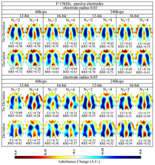
Figure 9.
Simulation results for 15 kHz input signal and passive electrode configuration. All further hardware configurations, as well as the corresponding s and s, are noted in the figure.
The presence of artefacts is a result of hardware noise and issues (electrode’s contact impedances, common signals between the channels, etc.), boundary and tissues’ motion, and the ill-posed and ill-conditioned nature of the inverse problem (low noise levels can lead to strong artefacts) [5,6,58]. When lower sampling rates or when a lower number of sampling periods () is set, the intense change of the lungs’ admittance near the chest is often not properly detected. This is verified quantitatively, where for ksps and , we obtain a between 0.58 and 0.71, while for ksps and , takes values between 0.58 and 0.77. The electrode’s surface area seems to be an important factor, since smaller surfaces lead to higher contact impedances. The contact impedance effect is more intense at lower frequencies [59,60]. Mismatches between the channels’ contact impedances may lead to common signals, especially at the voltage recording circuitry part. This can explain the improved performance ( of 0.68–0.77 and of 0.50–0.64) observed for an electrode radius of compared to this for the radius electrode configuration ( of 0.58–0.70 and of 0.61–0.78). Furthermore, a small electrode position deviation overall leads to minor additional image artefacts, assuming the same gap electrode model for each reconstruction. This is anticipated, since we enact difference-EIT imaging, where minor modelling errors are compensated [61]. Finally, as expected, an increase in the ADC resolution for 12 to 16 bits does not lead to significant reconstruction improvement with the presence of relatively high white noise levels (see Section 6.1 and Table 3).
Overall, for the 15 kHz passive electrode case and high white noise levels, we conclude that the electrode radius and the total number of taps per measurement (proportional to and ) are two key factors for the image reconstruction performance. In addition, according to (19), for lower analogue circuitry noise levels, the ADC resolution is also expected to boost the performance. However, such a case has not been simulated in this particular work.
The reconstructed images for kHz and passive electrode configuration are demonstrated in Figure 10. First of all, it is observed that the overall spatial resolution and image quality are reduced, compared to the corresponding 15 kHz case. Although the electrodes appear to have reduced contact impedances at this frequency, the parasitic effects taking place between the channel cables become more critical. These effects, combined with the reduced VCCS output impedance and instrumentation amplifier’s CMRR, lead to image quality degradation [5,7]. However, due to the low contact impedances, the electrodes’ surface does not significantly affect the performance ( between and , between and for the radius cases and between and , between and for the radius cases). As in the 15 kHz cases, the electrodes’ position deviation has a small impact on the images’ quality. The best results are obtained by increasing the number of taps per measurement (maximum is observed for Msps and sampling sine periods. A small improvement is observed when increasing the ADC resolution from 12 to 16 bits.
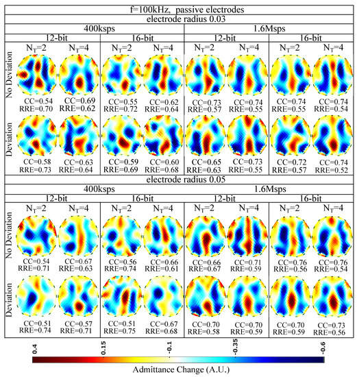
Figure 10.
Simulation results for 100 kHz input signal and passive electrode configuration. All further hardware configurations, as well as the corresponding s and s, are noted in the Figure.
The EIT images for kHz and the active (on the voltage recording part) electrode configuration are finally shown in Figure 11. A slight improvement of the image quality is detected, mainly due to the reduction of cable parasitic effects at the voltage measurement channels. The maximum of (corresponding minimum of ) is achieved for non-deviated, radius electrodes, when a 16 bit resolution ADC is utilized, sampling at Msps for sine periods. As in the passive electrode cases, the performance is less affected by the electrode deviation and the ADC resolution and mostly affected by the total number of taps per measurement channel. In addition, the electrode surface has minor effect on the performance, due to the lower contact impedances presented at kHz.
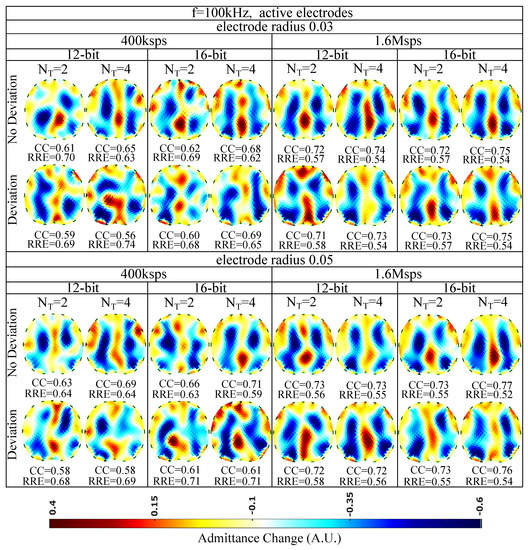
Figure 11.
Simulation results for 100 kHz input signal and active electrode configuration. All further hardware configurations, as well as the corresponding s and s, are noted in the Figure.
6.3. Discussion
From the results presented above, we can observe the effects of contact impedances, parasitic effects, noise, and shape mismatch under different hardware configurations and measurement frequencies. Specifically, the contact impedance effect becomes more intense at lower frequencies. However, the absence of capacitive effects and attenuation allows a moderate to good performance with a passive electrode configuration, which is achieved at 15 kHz (see Figure 9).
At higher input sinusoidal signal frequencies, the use of an active electrode configuration is essential for achieving a sufficient image quality by reducing the capacitive effects. Such systems have been already implemented in [4,16,18]. Fully active electrode EIT systems that implement the current source near each corresponding electrode pair have shown even better performance, since apart from the voltage channels’ parasitic effects, they compensate for the current channels’ ones. In [4], a comparison between passive and fully active electrode configurations on a lung-imaging EIT system has shown superior performance for the second case over a high frequency span. Hence, higher signal frequency spans can be achieved with active electrodes that allow higher temporal analysis which is essential for real-time lung imaging applications.
Furthermore, high noise levels from the circuitry can be taken care of by increasing the ADC sampling frequency and the number of sine periods that are sampled per measurement window. This leads to the increase of the number of taps K per measurement and benefits the values, according to (19). In this way, the matched LPFs’ performance is improved (after IQ demodulation) by actually performing signal averaging. Some systems, such as [16], use a high K per measurement window and achieve good voltage levels. However, increasing also increases the total time needed to take a measurement frame. As a result, lower image frame rates are obtained, significantly reducing the imaging temporal resolution. Therefore, lung imaging has to be performed at frequency rates above 100 kHz and relatively high sampling rates . In addition, these frequency ranges usually include valuable information about the thoracic tissues’ electrical behaviour [4]. Nonetheless, there is always a trade-off between signal noise and frame speed. Refs. [4,17], for example, achieve an imaging speed of more than 100 frames per second (fps) at a 1 MHz signal frequency; however, the rates fairly drop between 125 kHz and 1 MHz. On the other hand, ref. [16], which, as mentioned, uses a large number of filter taps, keeps a high by dropping the speed to lower than 20 fps. Moreover, another way to increase the is by enacting higher amplitude current signals. However, apart from the patients’ safety consideration, this solution demands higher power supplies and thus power consumption, which would be impractical in the case of active electrodes. The usage of a programmable gain amplifier (PGA), which amplifies the voltage signals collected from electrodes that are far from the current source pair, could also improve signal resistance to noise [7,23]. Finally, the effect of enacting different current patterns instead of the adjacent one to has been partially studied in [29]. Skip current patterns might increase the signal amplitude; however, sometimes they have a negative effect at the imaging reconstruction process, since they lead to a more ill-posed problem than the adjacent pattern. This happens due to the reduced number of electrode boundary measurements and the reduced number of independent measurements [34].
Finally, the shape mismatch between the chest (surface attached by electrode array) boundary and the reconstruction domain, as well as the boundary motion, leads to further image artefacts. Boundary tracking methods, such as the use of accelerometers, have recently been proposed to overcome this effect [4,11]. Although these methods can improve the image quality, they are often more expensive, due to the extra hardware needed. Furthermore, since the boundary motion due to the breath (or even the subject’s movement) is continuous, artefacts will be still present due to the fact that the reconstruction domain does not change through the imaging frames. Until now, such change in real-time thoracic EIT imaging applications is not applicable due to the complexity and time the mesh refinement needs. Therefore, compensation of motion-related imaging errors in EIT imaging applications is still a field under research.
A prior code implementation of the proposed interface can be found online on the following website: https://github.com/chdim100/SPICE-MATLAB-Interface-for-Electrical-Impedance-Tomography-Simulation-SPICEIT- (accessed on 4 August 2021).
7. Conclusions
An EIT simulation interface which makes use of Python, MATLAB, and LT SPICE software is applied in order to evaluate the impact of modelling, parasitic, and noise effects in thoracic imaging. The SUT is modelled as a fine F.E. structure, which is transformed to a multiport RLC circuitry block and merged in the analogue SPICE EIT circuitry. Transient and noise simulations are carried out in LT SPICE, while MATLAB creates the input data (input sinusoidal waveform and digital signals for the multiplexers’ control) and handles the output SPICE transient data to simulate the digital EIT hardware part. Configurations of the electrodes and the signal sampling are considered, and comparison of the results is performed. Simulations showed the significant effect of the channels’ impedances at low frequencies and passive-electrode configurations in reconstructions as well as the effect of the parasitic channels’ capacitors at higher frequencies. The active electrode configuration can compensate for these effects, while increasing the demodulation filter taps can increase the acquired signal and, as a result, the reconstructed image quality. This interface can be used as a valuable tool in EIT system design for prior estimation of custom EIT system performance under different analogue and digital part characteristics.
Author Contributions
Investigation, C.D., V.A. and I.G.; Writing—original draft, C.D. and V.A.; Writing—review and editing, C.D., V.A., I.G., N.U. and N.V. and P.P.S. All authors have read and agreed to the published version of the manuscript.
Funding
This research is co-financed by Greece and the European Union (European Social Fund—ESF) through the Operational Programme “Human +Resources Development, Education and Lifelong Learning” in the context of the project “Strengthening Human Resources Research Potential via Doctorate Research” (MIS-5000432), implemented by the State Scholarships Foundation (IKY).
Conflicts of Interest
The authors declare no conflict of interest.
References
- Holder, D.S. (Ed.) Electrical Impedance Tomography: Methods, History and Applications; CRC Press: Boca Raton, FL, USA, 2004. [Google Scholar]
- Bodenstein, M.; David, M.; Markstaller, K. Principles of electrical impedance tomography and its clinical application. Crit. Care Med. 2009, 37, 713–724. [Google Scholar] [CrossRef] [PubMed]
- Adler, A.; Boyle, A. Electrical Impedance Tomography: Tissue properties to image measures. IEEE Trans. Biomed. Eng. 2017, 64, 2494–2504. [Google Scholar] [PubMed]
- Wu, Y.; Jiang, D.; Bardill, A.; Bayford, R.; Demosthenous, A. A 122 fps, 1 MHz bandwidth multi-frequency wearable EIT belt featuring novel active electrode architecture for neonatal thorax vital sign monitoring. IEEE Trans. Biomed. Circuits Syst. 2019, 13, 927–937. [Google Scholar] [CrossRef]
- Wu, Y.; Hanzaee, F.F.; Jiang, D.; Bayford, R.H.; Demosthenous, A. Electrical Impedance Tomography for Biomedical Applications: Circuits and Systems Review. IEEE Open J. Circuits Syst. 2021, 2, 380–397. [Google Scholar] [CrossRef]
- Lionheart, W.R. EIT reconstruction algorithms: Pitfalls, challenges and recent developments. Physiol. Meas. 2004, 25, 125. [Google Scholar] [CrossRef] [PubMed]
- Shi, X.; Li, W.; You, F.; Huo, X.; Xu, C.; Ji, Z.; Dong, X. High-precision electrical impedance tomography data acquisition system for brain imaging. IEEE Sens. J. 2018, 18, 5974–5984. [Google Scholar] [CrossRef]
- Nguyen, D.T.; Jin, C.; Thiagalingam, A.; McEwan, A.L. A review on electrical impedance tomography for pulmonary perfusion imaging. Physiol. Meas. 2012, 33, 695. [Google Scholar] [CrossRef]
- Rao, A.; Teng, Y.C.; Schaef, C.; Murphy, E.K.; Arshad, S.; Halter, R.J.; Odame, K. An analog front end ASIC for cardiac electrical impedance tomography. IEEE Trans. Biomed. Circuits Syst. 2018, 12, 729–738. [Google Scholar] [CrossRef]
- Grychtol, B.; Lionheart, W.R.; Bodenstein, M.; Wolf, G.K.; Adler, A. Impact of model shape mismatch on reconstruction quality in electrical impedance tomography. IEEE Trans. Med. Imaging 2012, 31, 1754–1760. [Google Scholar] [CrossRef]
- Biguri, A.; Grychtol, B.; Adler, A.; Soleimani, M. Tracking boundary movement and exterior shape modelling in lung EIT imaging. Physiol. Meas. 2015, 36, 1119. [Google Scholar] [CrossRef][Green Version]
- Wilson, A.J.; Milnes, P.; Waterworth, A.R.; Smallwood, R.H.; Brown, B.H. Mk3.5: A modular, multi-frequency successor to the Mk3a EIS/EIT system. Physiol. Meas. 2000, 22, 49–54. [Google Scholar] [CrossRef]
- Cook, R.D.; Saulnier, G.J.; Gisser, D.G.; Goble, J.C.; Newell, J.C.; Isaacson, D. ACT3: A high-speed, high-precision electrical impedance tomograph. IEEE Trans. Biomed. Eng. 1994, 41, 713–722. [Google Scholar] [CrossRef]
- Liu, N.; Saulnier, G.J.; Newell, J.C.; Isaacson, D.; Kao, T.-J. ACT4: A high-precision, multi-frequency electrical impedance tomograph. In Proceedings of the 6th Conference on Biomedical Applications of Electrical Impedance Tomography, London, UK, 22–24 June 2005. [Google Scholar]
- Wi, H.; Sohal, H.; McEwan, A.L.; Woo, E.J.; Oh, T.I. Multi-Frequency Electrical Impedance Tomography System With Automatic Self-Calibration for Long-Term Monitoring. IEEE Trans. Biomed. Circuits Syst. 2013, 8, 119–128. [Google Scholar]
- Mellenthin, M.M.; Mueller, J.L.; De Camargo, E.D.L.B.; De Moura, F.S.; Santos, T.B.R.; Lima, R.G.; Alsaker, M. The ACE1 electrical impedance tomography system for thoracic imaging. IEEE Trans. Instrum. Meas. 2018, 68, 3137–3150. [Google Scholar] [CrossRef]
- Wu, Y.; Jiang, D.; Bardill, A.; De Gelidi, S.; Bayford, R.; Demosthenous, A. A high frame rate wearable EIT system using active electrode ASICs for lung respiration and heart rate monitoring. IEEE Trans. Circuits Syst. I Regul. Pap. 2018, 65, 3810–3820. [Google Scholar] [CrossRef]
- Gaggero, P.O.; Adler, A.; Brunner, J.; Seitz, P. Electrical impedance tomography system based on active electrodes. Physiol. Meas. 2012, 33, 831. [Google Scholar] [CrossRef] [PubMed]
- Guermandi, M.; Cardu, R.; Scarselli, E.F.; Guerrieri, R. Active electrode IC for EEG and electrical impedance tomography with continuous monitoring of contact impedance. IEEE Trans. Biomed. Circuits Syst. 2014, 9, 21–33. [Google Scholar] [CrossRef]
- XMurphy, E.K.; Takhti, M.; Skinner, J.; Halter, R.J.; Odame, K. Signal-to-noise ratio analysis of a phase-sensitive voltmeter for electrical impedance tomography. IEEE Trans. Biomed. Circuits Syst. 2016, 11, 360–369. [Google Scholar] [CrossRef]
- Takhti, M.; Odame, K. Structured design methodology to achieve a high SNR electrical impedance tomography. IEEE Trans. Biomed. Circuits Syst. 2019, 13, 364–375. [Google Scholar] [CrossRef]
- Takhti, M.; Odame, K. A power adaptive, 1.22-pW/Hz, 10-MHz read-out front-end for bio-impedance measurement. IEEE Trans. Biomed. Circuits Syst. 2019, 13, 725–734. [Google Scholar] [CrossRef]
- Rao, A.; Murphy, E.K.; Halter, R.J.; Odame, K.M. A 1 MHz miniaturized electrical impedance tomography system for prostate imaging. IEEE Trans. Biomed. Circuits Syst. 2020, 14, 787–799. [Google Scholar] [CrossRef] [PubMed]
- Eberdt, M.; Brown, P.K.; Lazzi, G. Two-dimensional SPICE-linked multiresolution impedance method for low-frequency electromagnetic interactions. IEEE Trans. Biomed. Eng. 2003, 50, 881–889. [Google Scholar] [CrossRef]
- Boyle, A.; Adler, A. Integrating Circuit Simulation with EIT FEM Models. In Proceedings of the 19th Conference on Biomedical Applications of Electrical Impedance Tomography, Edinburgh, UK, 11–13 June 2018; p. 20. [Google Scholar]
- Adler, A.; Lionheart, W.R. Uses and abuses of EIDORS: An extensible software base for EIT. Physiol. Meas. 2006, 27, S25. [Google Scholar] [CrossRef]
- Dimas, C.; Uzunoglu, N.; Sotiriadis, P.P. Electrical impedance tomography image reconstruction: Impact of hardware noise and errors. In Proceedings of the 2019 8th International Conference on Modern Circuits and Systems Technologies (MOCAST), Thessaloniki, Greece, 13–15 May 2019; pp. 1–4. [Google Scholar]
- Dimas, C.; Uzunoglu, N.; Sotiriadis, P.P. A parametric EIT system spice simulation with phantom equivalent circuits. Technologies 2020, 8, 13. [Google Scholar] [CrossRef]
- Dimas, C.; Alimisis, V.; Sotiriadis, P.P. SPICE and MATLAB simulation and evaluation of Electrical Impedance Tomography readout chain using phantom equivalents. In Proceedings of the 2020 European Conference on Circuit Theory and Design (ECCTD), Sofia, Bulgaria, 7–10 September 2020; pp. 1–4. [Google Scholar]
- Adler, A.; Gaggero, P.O.; Maimaitijiang, Y. Adjacent stimulation and measurement patterns considered harmful. Physiol. Meas. 2011, 32, 731. [Google Scholar] [CrossRef] [PubMed]
- Tomicic, V.; Cornejo, R. Lung monitoring with electrical impedance tomography: Technical considerations and clinical applications. J. Thorac. Dis. 2019, 11, 3122. [Google Scholar] [CrossRef]
- Kolehmainen, V.; Vauhkonen, M.; Karjalainen, P.A.; Kaipio, J.P. Assessment of errors in static electrical impedance tomography with adjacent and trigonometric current patterns. Physiol. Meas. 1997, 18, 289. [Google Scholar] [CrossRef]
- Dimas, C.; Sotiriadis, P.P. Electrical impedance tomography image reconstruction for adjacent and opposite strategy using FEMM and EIDORS simulation models. In Proceedings of the 2018 7th International Conference on Modern Circuits and Systems Technologies (MOCAST), Thessaloniki, Greece, 7–9 May 2018; pp. 1–4. [Google Scholar]
- Silva, O.L.; Lima, R.G.; Martins, T.C.; De Moura, F.S.; Tavares, R.S.; Tsuzuki, M.S.G. Influence of current injection pattern and electric potential measurement strategies in electrical impedance tomography. Control Eng. Pract. 2017, 58, 276–286. [Google Scholar] [CrossRef]
- Simini, F.; Bertemes-Filho, P. Bioimpedance in Biomedical Applications and Research; Springer: New York, NY, USA, 2018. [Google Scholar]
- Avery, J.; Dowrick, T.; Witkowska-Wrobel, A.; Faulkner, M.; Aristovich, K.; David, H. Simultaneous EIT and EEG using frequency division multiplexing. Physiol. Meas. 2019, 40, 3. [Google Scholar] [CrossRef]
- Kassanos, P.; Constantinou, L.; Triantis, I.F.; Demosthenous, A. An integrated analog readout for multi-frequency bioimpedance measurements. IEEE Sens. J. 2018, 14, 2792–2800. [Google Scholar] [CrossRef]
- Hong, S.; Lee, J.; Bae, J.; Yoo, H.J. A 10.4 mW electrical impedance tomography SoC for portable real-time lung ventilation monitoring system. IEEE J. Solid-State Circuits 2015, 50, 2501–2512. [Google Scholar] [CrossRef]
- Schöberl, J. NETGEN An advancing front 2D/3D-mesh generator based on abstract rules. Comput. Vis. Sci. 1997, 1, 41–52. [Google Scholar] [CrossRef]
- Gabriel, S.; Gabriel, C.; Corthout, E. The dielectric properties of biological tissues: I. Literature survey. Phys. Med. Biol. 1996, 68, 2231. [Google Scholar] [CrossRef]
- Gabriel, S.; Lau, R.; Gabriel, C. The dielectric properties of biological tissues: II. Measurements in the frequency range 10 Hz to 20 GHz. Phys. Med. Biol. 1996, 41, 2251. [Google Scholar] [CrossRef] [PubMed]
- Gabriel, S.; Lau, R.; Gabriel, C. The dielectric properties of biological tissues: III. parametric models for the dielectric spectrum of tissues. Phys. Med. Biol. 1996, 41, 2271. [Google Scholar] [CrossRef] [PubMed]
- Liu, D.; Kolehmainen, V.; Siltanen, S.; Laukkanen, A.M.; Seppänen, A. Nonlinear difference imaging approach to three-dimensional electrical impedance tomography in the presence of geometric modeling errors. IEEE Trans. Biomed. Eng. 2015, 63, 1956–1965. [Google Scholar] [CrossRef]
- Hyvönen, N. Complete electrode model of electrical impedance tomography: Approximation properties and characterization of inclusions. SIAM J. Appl. Math. 2004, 64, 902–931. [Google Scholar] [CrossRef]
- Polydorides, N. Image Reconstrucion Algorithms for Soft-Field Tomography. Ph.D. Thesis, University of Manchester Institute of Science and Technology, Manchester, UK, 2002. [Google Scholar]
- Proenca, M. Resistor Networks and Finite Element Models. Ph.D. Thesis, University of Manchester, Manchester, UK, 2011. [Google Scholar]
- Franks, W.; Schenker, I.; Schmutz, P.; Hierlemann, A. Impedance Characterization and Modeling of Electrodes for Biomedical Applications. IEEE Trans. Biomed. Eng. 2005, 52, 7. [Google Scholar] [CrossRef]
- Da Silveira, D.V.; Button, N. Principles of Measurement and Transduction of Biomedical Variables; Academic Press (Elsevier): Cambridge, MA, USA, 2015. [Google Scholar]
- Albulbul, A. Evaluating Major Electrode Types for Idle Biological Signal Measurements for Modern Medical Technology. Bioengineering 2016, 3, 20. [Google Scholar] [CrossRef] [PubMed]
- Vauhkonen, M.; Vadasz, D.; Karjalainen, P.A.; Somersalo, E.; Kaipio, J.P. Tikhonov regularization and prior information in electrical impedance tomography. IEEE Trans. Med. Imaging 1998, 17, 285–293. [Google Scholar] [CrossRef]
- Hamilton, S.J.; Hauptmann, A. Deep D-bar: Real-time electrical impedance tomography imaging with deep neural networks. IEEE Trans. Med. Imaging 2020, 37, 2367–2377. [Google Scholar] [CrossRef]
- Liu, S.; Jia, J.; Zhang, Y.D.; Yang, Y. Image reconstruction in electrical impedance tomography based on structure-aware sparse Bayesian learning. IEEE Trans. Med. Imaging 2018, 37, 2090–2102. [Google Scholar] [CrossRef] [PubMed]
- Liu, S.; Cao, R.; Huang, Y.; Ouypornkochagorn, T.; Jia, J. Time sequence learning for electrical impedance tomography using Bayesian spatiotemporal priors. IEEE Trans. Instrum. Meas. 2020, 69, 6045–6057. [Google Scholar] [CrossRef]
- Cheng, K.S.; Isaacson, D.; Newell, J.C.; Gisser, D.G. Electrode models for electric current computed tomography. IEEE Trans. Biomed. Eng. 1989, 36, 918–924. [Google Scholar] [CrossRef] [PubMed]
- Somersalo, E.; Cheney, M.; Isaacson, D. Existence and uniqueness for electrode models for electric current computed tomography. SIAM J. Appl. Math. 1992, 52, 1023–1040. [Google Scholar] [CrossRef]
- Brown, B.H.; Seagar, A.D. The Sheffield data collection system. Clin. Phys. Physiol. Meas. 1987, 8, 91. [Google Scholar] [CrossRef]
- Adler, A.; Arnold, J.H.; Bayford, R.; Borsic, A.; Brown, B.; Dixon, P.; Faes, T.J.; Frerichs, I.; Gagnon, H.; Gärber, Y.; et al. GREIT: A unified approach to 2D linear EIT reconstruction of lung images. Physiol. Meas. 2009, 30, S35. [Google Scholar] [CrossRef] [PubMed]
- Martin, S.; Choi, C.T. A post-processing method for three-dimensional electrical impedance tomography. Sci. Rep. 2017, 7, 1–10. [Google Scholar] [CrossRef]
- Alimisis, V.; Dimas, C.; Pappas, G.; Sotiriadis, P.P. Analog Realization of Fractional-Order Skin-Electrode Model for Tetrapolar Bio-Impedance Measurements. Technologies 2020, 8, 61. [Google Scholar] [CrossRef]
- Yang, L.; Dai, M.; Xu, C.; Zhang, G.; Li, W.; Fu, F.; Shi, X.; Dong, X. The frequency spectral properties of electrode-skin contact impedance on human head and its frequency-dependent effects on frequency-difference EIT in stroke detection from 10 Hz to 1 MHz. PLoS ONE 2017, 12, e0170563. [Google Scholar] [CrossRef]
- Soleimani, M.; Gómez-Laberge, C.; Adler, A. Imaging of conductivity changes and electrode movement in EIT. Physiol. Meas. 2006, 27, S103. [Google Scholar] [CrossRef] [PubMed]
Publisher’s Note: MDPI stays neutral with regard to jurisdictional claims in published maps and institutional affiliations. |
© 2021 by the authors. Licensee MDPI, Basel, Switzerland. This article is an open access article distributed under the terms and conditions of the Creative Commons Attribution (CC BY) license (https://creativecommons.org/licenses/by/4.0/).