Abstract
In the present work, the radiation properties of a graphene plasmonic patch antenna are investigated and enhanced in terms of efficiency, utilizing circuit-matching techniques. Initially, the reflection coefficient of graphene surface waves due to discontinuities is studied, while the power flow towards free-space is numerically extracted. This analysis indicates that the radiated power is increased for higher values of the chemical potential, although the surface wave is weakly confined and prone to degradation due to interference. For this reason, a graphene sheet that supports strongly confined surface waves is terminated via a matching layer, in order to enhance the radiating power. In particular, the matching layer consists of an appropriately selected larger chemical potential value, in order to minimize the reflection coefficient and boost the radiation performance. The numerical investigation of this setup validates the upgraded performance, since the radiating power is significantly increased. Then, a realistic setup that includes a graphene patch antenna is examined numerically, proving the augmentation of the radiation efficiency when the matching layer is utilized. Finally, the latter is designed with a graded increment in the chemical potential, and the computational analysis highlights the significant enhancement of the graphene plasmonic antenna gain towards the desired direction. Consequently, a more reliable framework for wireless communications between plasmonic devices at THz frequencies is established, which corresponds to the practical significance of the proposed methodology for improved radiation efficiency. All numerical results are extracted by means of an efficient modification of the Finite-Difference Time-Domain (FDTD) scheme, which models graphene accurately.
1. Introduction
Wireless communications at nanoscale have recently become a rapidly emerging field due to their promising features in various applications, including the biomedical, environmental, and industrial sectors [1,2,3,4]. A crucial factor for reliable communications in a nano-network is the optimized design of the radiating elements, i.e. the nano-antennas. Although classic metallic antennas demonstrate excellent behavior at microwave and millimeter-wave frequencies, their efficiency is drastically degraded as the spectrum approaches the far-infrared region [5,6]. Specifically, the conductivity of metals is considerably decreased and the subsequent thermal losses are producing high energy consumption rates, which can be partially compensated only via more complex implementations of cumbersome realizations. Therefore, alternative materials need to be considered.
To this aim, the popular two-dimensional carbon allotrope, namely graphene, is a serious candidate to substitute conventional conductors due to its exotic properties [7,8,9]. From an electromagnetic point of view, it features finite conductivity despite its negligible thickness, and, as a result, various interesting phenomena are enabled. One of the latter pertains to the graphene’s ability to support transverse magnetic (TM) surface plasmon polariton (SPP) waves [10,11,12] of strong confinement and decreased wavelength, compared to propagation in free space. This enables the miniaturization of devices operating at frequencies from the far-infrared spectrum and beyond. The propagation features above the graphene surface are affected by its conductivity that depends on certain controllable parameters, such as the selected substrate and the applied gate voltage. Consequently, it is feasible to achieve a short wavelength of the surface wave, keeping at the same time the attenuation at low levels.
In this framework, various advanced implementations have been proposed until today, such as a wide class of absorbers [13,14,15,16], plasmonic filters [17,18], polarizers [19,20], and modulators [21,22]. Moreover, several fundamental graphene plasmonic antennas have been designed throughout the past years [23,24,25,26,27]. However, the major disadvantage of the radiating plasmonic realizations is the degraded radiation efficiency, due to the considerable mismatch between the surface wave and the free-space propagation constants, where the radiating power is guided. To this end, a number of implementations have been considered either focusing at lower frequencies [28,29], where the wavelength is approaching that of free space, or restoring the dimensions using advanced materials [30].
The purpose of the present work is to examine the radiated power from graphene discontinuities, in order to design a proper setup that increases the radiation efficiency of graphene plasmonic antennas. Initially, the surface wave propagation characteristics are investigated theoretically, to highlight their mismatch with respect to the free-space propagation. Specifically, as the radiated power from the advantageous strongly-confined surface waves is considerably degraded, a termination via a matching component is proposed. The latter is composed of graphene with increased chemical potential, in order to support surface waves of lower effective index, thus ensuring improved radiation capability into free space. This implementation can be considered beneficial, since the graphene input impedance is approaching the one of photomixers [31], favoring the surface wave coupling. At the same time, the radiated power is also increased. As a result, the next step is to design a realistic setup that is analyzed numerically by means of an accurate Finite-Difference Time-Domain (FDTD) method, which models graphene as an equivalent surface conductivity [32] in an optimized manner [33]. The extracted results validate the enhanced radiation efficiency, while an extra setup featuring graded chemical potential is proposed for further optimization.
2. Materials and Methods
2.1. Surface Conductivity
Graphene is considered a truly two-dimensional material and is sufficiently characterized by its surface conductivity , where is the radian frequency, the chemical potential controlled either by chemical doping or by an applied gate voltage, a phenomenological scattering rate assumed to be independent of energy, and T the temperature. Graphene’s conductivity is evaluated by the following compact expression resulting from the Kubo formula [34],
with being the electron charge, ħ the reduced Planck’s constant, and the Fermi-Dirac distribution. The second term in (1), indicating the interband contributions, is negligible compared to the dominant first term, due to the intraband contributions at the frequencies of our interest. Consequently, the second term can be safely ignored. Now, the expression of graphene’s conductivity is significantly simplified and, thus, calculated via
2.2. Surface Wave Propagation Properties
It is well known that graphene is capable of supporting strongly confined TM SPP waves on its surface, mainly beyond the far-infrared spectrum, with propagation properties dependent on the surface conductivity. In the general case of an infinite graphene layer located between two dielectrics with relative permittivities and , the complex propagation constant of the surface wave is computed through [11]
where and are the vacuum’s wavenumber and wave-impedance, respectively, and is the graphene’s surface conductivity (2). Although the propagation properties of graphene surface waves are determined via , the more intuitive effective index is introduced, estimated via
This term is important because it is a metric of the SPP wave characteristics compared to the free-space one. Specifically, the real part of the effective index indicates the confinement of the surface wave, as well as the wavelength ratio between the SPP versus the free-space waves, while the imaginary part corresponds to the propagation length. For instance, the effective index is calculated via (3) and (4) for a popular setup that includes graphene atop silicon-oxide substrate of , considering various chemical potential values at THz. The result is depicted in Figure 1, and it is observed that the SPP wavelength is almost 6 times shorter than the free-space wavelength, at the lowest chemical potential values.
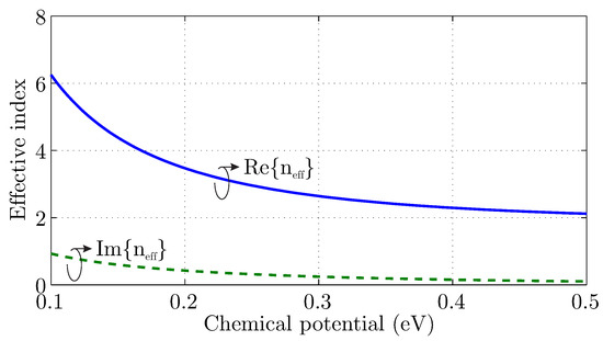
Figure 1.
Effective index of an surface plasmon polariton (SPP) wave, for graphene atop silicon-oxide at THz and various chemical potential values.
2.3. Reflection Due to Graphene Discontinuities
The behavior of the surface wave propagation due to discontinuities of graphene constitutes an additional important aspect. In particular, graphene parameters (such as the bias-controlled chemical potential) may vary, and a surface wave with different attributes is supported. Moreover, a termination of the two-dimensional layer forces the surface wave to be properly converted into a spherical one that propagates towards the free space. In either case, the investigation of the reflected and transmitted power is significant for the design of optimally efficient graphene devices.
The first scenario is illustrated in Figure 2a and describes the transition of the surface wave from a graphene layer with , to a different one with . In this case, Fresnel equations are applicable, since both waves display similar behavior, namely evanescent fields perpendicular to graphene surface. The reflection coefficient r for normal incidence is calculated from:

Figure 2.
Surface wave propagation on graphene towards (a) a layer with different properties and (b) free-space.
However, Fresnel equations are not completely valid, when the reflection due to graphene layer termination is examined (as in Figure 2b), since the strongly confined surface wave must be converted into a spherical one. Here, (5) yields a qualitative result for the reflection coefficient, rather than an exact result formula. Particularly, the reflection coefficient is not calculated accurately, although the mismatch is indeed stronger for larger effective index values of the graphene surface wave (namely, small values of chemical potential).
The last observation initiates the proposed implementation, where a matching component is included as a termination of the device, in order to enhance the radiation towards free space. Thereby, a surface wave of increased effective index with advantageous propagation attributes, namely strong confinement that minimizes interference, is terminated by one with a decreased effective index, for optimal radiation. The termination component is the same graphene layer as the conventional device, which is biased differently, in order to achieve increased chemical potential and, as a result, a better matching with free space, bearing in mind Figure 1. The equivalent setup is illustrated in Figure 2b, where is the original graphene layer, and is the matching component of thickness d. It is worth mentioning that the chemical potential is either constant or gradually increasing through the formula
In the above equation, x is the distance from the initial edge to matching-layer edge, n is the increment grade, and is a constant factor, determined through the desired maximum chemical potential value at graphene to free-space edge, by means of
Additionally, a realistic 3D setup is considered, namely a graphene antenna of total length L and width w, as demonstrated in Figure 3. This apparatus consists of a microstrip atop a silica (SiO2) substrate, while a dipole source is placed at its center. Although the attributes of this setup are considerably more complicated, due to the propagation of several surface wave modes, such as bulk and edge ones [35], it will be shown that the fundamental aspects of graphene termination using matching component of thickness d can enhance the antenna’s radiation efficiency. Finally, the graphene bias () electrodes can be placed at the patch’s side, where the radiation is minimum, and, thus, their influence should be negligible.
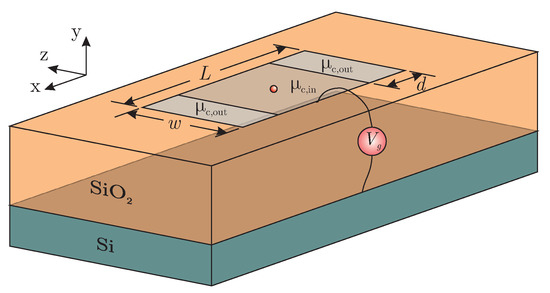
Figure 3.
The proposed graphene antenna with a matching component as termination.
3. Results and Discussion
The aforementioned analysis is validated numerically by means of a properly modified FDTD technique that models graphene as an equivalent surface current density [33]. The results are separated in two categories, as discussed in the previous section. Specifically, the simpler case of a propagating surface wave is considered initially, followed by the numerical investigation concerning a graphene antenna. Note that graphene scattering rate is set meV at temperature K for all numerical simulations. The scattering rate value is a typical one for a good quality graphene layer, while T coincides with the standard room temperature. Additionally, graphene surface conductivity is thermally stable for moderate fluctuations around this temperature [36].
3.1. Surface Wave Reflection and Power Flow towards Free-Space
In this scenario, a planar graphene surface wave is considered atop a silica substrate of , as illustrated in Figure 2, and a TE version of the FDTD algorithm is implemented. The computational domain is divided in elementary square cells of edge dimension m, while the time-step is set to fs to secure the algorithm’s stability. The analysis performed at THz. Note that the cell size is selected almost 60 times smaller than the free-space wavelength, due to the significantly decreased graphene surface-wave wavelength. Finally, open boundaries are truncated via an effective 8-cell Perfectly Matched Layer (PML).
First of all, the transition of a surface wave from a graphene layer with chemical potential to another one with is investigated. The chemical potential alteration results in a different effective index of the surface wave, as discussed in the previous section and depicted in Figure 2a. The reflection coefficient is extracted via the numerical algorithm at the point nearest to the edge, in order to minimize the effect of propagation losses, while is set to eV altering . The results are sketched in Figure 4, where the match with the Fresnel equation in (5) is evident, since the main attributes of the propagating surface wave are retained.
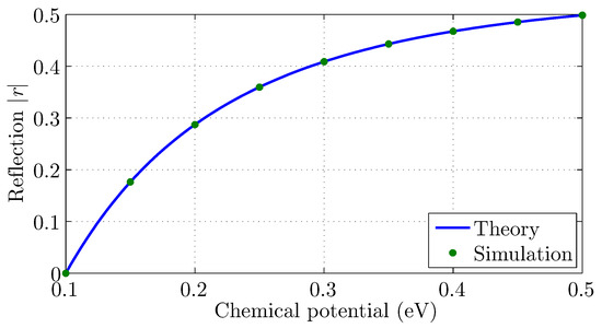
Figure 4.
Reflection coefficient of a graphene surface wave due to chemical potential discontinuity.
Nevertheless, the reflection coefficient for the transition of the surface wave towards free space is not estimated accurately via (5), and a numerical computation should be performed. The equivalent setup is depicted in Figure 2b for , and Figure 5a illustrates the extracted reflection coefficient. The latter is reduced as the graphene chemical potential increases, due to the surface wave effective index reduction (Figure 1). In fact, their relationship is almost linear. Additionally, the radiated power is measured as a percentage of the delivered one to the graphene edge. Specifically, the power flow towards free space is evaluated numerically, and compared to that of the incident surface wave near the edge. The radiated power, demonstrated in Figure 5a, is approximately for the lowest chemical potential value, namely eV, while it approaches for eV. It is worth mentioning that the radiated power is also influenced by the distance between the surface wave source and the graphene edge. This is illustrated in Figure 5b for three different chemical potential values, proving that the efficiency is degraded for a source location near the edge, while an descending oscillatory behavior is observed for eV. For this reason, the setup that provides the maximum radiated power is selected, in order to secure a fair comparison.
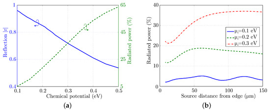
Figure 5.
(a) Surface wave reflection coefficient and power flow to free-space for graphene with different chemical potentials. (b) Power flow to free-space versus surface wave source distance from graphene edge.
It is now obvious that a graphene surface wave of low effective index is advantageous for enhanced radiation. However, this wave is also weakly confined to the graphene surface, leading to a degradation of the device performance due to interference. Consequently, a strongly confined surface wave is required for the initial propagation, while a matching component with enhanced radiation features is included for termination, as demonstrated in Figure 2. In this setup, low values are selected for and higher ones for , in order to achieve the appropriate effective index, according to Figure 1. The performance is tested for eV and various values, as well as thicknesses d. Initially, the reflection coefficient is calculated and sketched in Figure 6a, indicating that a thicker matching component achieves better behavior. Moreover, the optimized solution is obtained for approximately eV, due to the severe mismatch between the effective indices of the surface waves for even higher values, as observed in Figure 4. Similar results are extracted via the radiation power examination in Figure 6b, validating the enhanced performance of the proposed setup. Specifically, the radiating power is augmented by almost five times compared to the setup without a matching component, for eV and m. Note a slight shift of the extreme value as the thickness d is altered, which is mainly due to the interference of the surface wave multiple reflections.
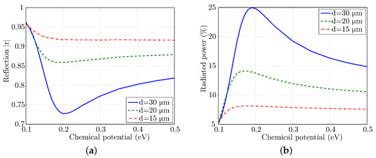
Figure 6.
Surface wave (a) reflection coefficient and (b) power flow to free-space for a graphene layer of eV with matching component termination of different chemical potential.
Additionally, a graded increment of the chemical potential in the matching component is utilized with a maximum value eV. The results in Figure 7 reveal an improved performance by approximately times compared to the setup without matching component, especially for a grading factor and m. However, this improvement is not better than the constant value.
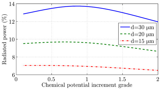
Figure 7.
Surface wave power flow to free space for a graphene layer of eV with matching component termination of graded chemical potential increment.
3.2. Performance Enhancement of Graphene Antenna
The second scenario includes the graphene microstrip antenna of Figure 3, with m, m and m. The computational domain is divided in elementary cubic cells of edge dimension m, while the time-step is set to fs to secure the algorithm’s stability. The analysis is performed at THz. Note, again, that the cell size is almost 30 times lower than the free-space wavelength due to the significantly decreased graphene surface wave wavelength. Finally, open boundaries are truncated via an effective 8-cell Perfectly Matched Layer (PML).
The extracted results correspond to the radiation properties of the proposed antenna, as described by the antenna efficiency and the radiation pattern. The former is illustrated in Figure 8, and it displays the expected increase, especially for chemical potential values of the matching component larger than eV. Moreover, the normalized gain is evaluated towards the desired direction, namely the -plane (where the matching component is placed), indicating that the maximization is succeeded approximately at eV. This behavior is equivalent to that of the previous section, where the maximum radiated power is also observed near the eV value. It is worth it to mention that the inconsistency between the efficiency and the gain in Figure 8 can be explained via the radiation mechanism through the side edges of the patch, due to the increased reflection from towards . In addition, the maximization of the directivity for eV is validated by examining the radiation pattern of the proposed antenna in Figure 9a. This is an expected outcome since this specific chemical potential value offers increased radiating performance, while the reflected wave at the interface is at low levels. As the chemical potential increases, the reflection coefficient at the interface is increased, resulting in degraded attributes. Finally, it is worth it to mention that the main lobe of the radiation pattern is towards the silica substrate.
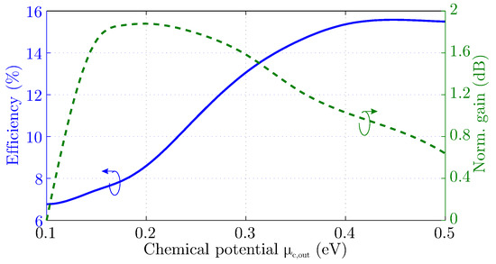
Figure 8.
Radiation efficiency and normalized gain at the direction of desired propagation for different chemical potential values of the matching component.
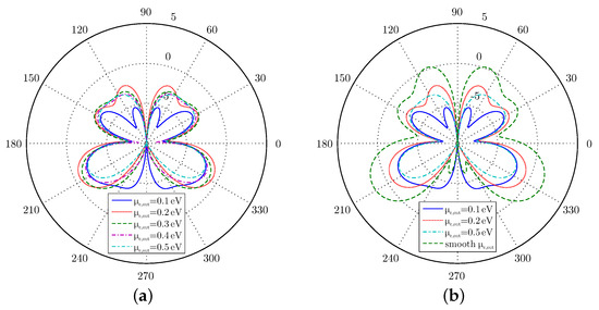
Figure 9.
Radiation pattern at plane (a) for different chemical potential constant values of the matching component and (b) including a step-like matching component.
Further investigation is conducted regarding the matching component by introducing a smoother transition to the free-space, in particular a graded increment of the chemical potential. The numerical analysis of this graphene antenna reveals that the gain, compared to a constant value eV, is increased by dB. This is larger than any value in Figure 8. This observation is also clear in Figure 9b, where several radiation patterns are sketched on the -plane. Obviously, the smooth-transition features that resemble free-space propagation are enhancing the directivity of the antenna. This functionality is not observed in the previous section, since the finite width of the graphene in Figure 3 alters the SPP propagation features, and both edge and bulk modes are supported.
Furthermore, the electric field on the -plane is computed, in order to examine the physical aspects of radiation. In Figure 10, the corresponding amplitude is illustrated and an initial observation pertains to the increased field concentration inside the substrate, due to the higher relative permittivity value. This explains the generation of the two main lobes towards and . Additionally, the reflection due to the steep transition of SPP wave from eV towards eV (Figure 10b) is visible, since the surface wave is weak at the matching component region. For this reason, the radiation of this device is realized, mainly, via the side edges and corners of the patch, as verified by the 3D radiation pattern in Figure 11b. Here, four directive main lobes appear that correspond to the concentration of the electric field at the patch corners. The radiation pattern for the case eV in Figure 11a, also presents four lobes. Yet, their directivity is considerably decreased. The most interesting radiation pattern is observed in Figure 11c, for the antenna with a matching component of graded increment in the chemical potential. Here, it is obvious that the radiation leakage through the patch’s corners is unavoidable. Nevertheless, the main lobe is the one that corresponds to the desired direction, namely the one that the matching component is placed. Consequently, the optimized transmission of the SPP wave to free-space is accomplished.
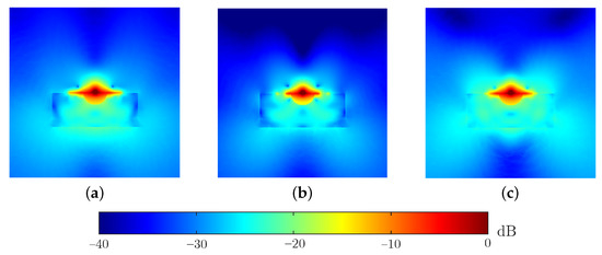
Figure 10.
Distribution of the electric field amplitude at plane for (a) eV, (b) eV, and (c) graded increment of matching component’s chemical potential.

Figure 11.
Three-dimensional radiation patterns of the proposed graphene antenna for (a) eV, (b) eV, and (c) graded increment of matching component’s chemical potential.
4. Conclusions
The enhancement of a graphene plasmonic patch antenna’s radiation efficiency, with the aid of matching components, has been discussed in this work. Initially, the propagation characteristics of surface waves on graphene have been investigated, indicating that the shorter ones are avoiding parasitic interferences efficiently. Yet, they present poor matching to free-space waves. As a consequence, the entire concept is based on the incorporation of a component that facilitates the transition from the short graphene SPP wavelength to free space. To this end, graphene chemical potential is adjusted appropriately at the plasmonic patch’s limit via the simple increment of the applied bias voltage. Numerical results indicate that the radiating power can be maximized by smoothly varying the propagation properties of the matching component. In this way, optimized transmission is achieved. Consequently, the wireless communication between plasmonic devices at THz regime is more reliable, requiring decreased energy consumption.
Author Contributions
Conceptualization, S.A.; Investigation, S.A.; Methodology, S.A.; Supervision, T.Z. and N.K.; Validation, S.A.; Writing—original draft, S.A.; Writing—review and editing, S.A., T.Z. and N.K. All authors have read and agreed to the published version of the manuscript.
Funding
This research is co-financed by Greece and the European Union (European Social Fund—ESF) through the Operational Programme «Human Resources Development, Education and Lifelong Learning» in the context of the project “Reinforcement of Postdoctoral Researchers—2nd Cycle” (MIS-5033021), implemented by the State Scholarships Foundation (IKY).

Institutional Review Board Statement
Not applicable.
Informed Consent Statement
Not applicable.
Data Availability Statement
The data presented in this study are available in Section 3.1 and Section 3.2 via a straightforward reproduction of the provided simulation details.
Conflicts of Interest
There is no conflict of interest.
References
- Samaddar, P.; Son, Y.S.; Tsang, D.C.; Kim, K.H.; Kumar, S. Progress in graphene-based materials as superior media for sensing, sorption, and separation of gaseous pollutants. Coord. Chem. Rev. 2018, 368, 93–114. [Google Scholar] [CrossRef]
- Perreault, F.; De Faria, A.F.; Elimelech, M. Environmental applications of graphene-based nanomaterials. Chem. Soc. Rev. 2015, 44, 5861–5896. [Google Scholar] [CrossRef]
- Zhang, Y.; Nayak, T.R.; Hong, H.; Cai, W. Graphene: A versatile nanoplatform for biomedical applications. Nanoscale 2012, 4, 3833–3842. [Google Scholar] [CrossRef] [PubMed]
- Akyildiz, I.F.; Jornet, J.M. Electromagnetic wireless nanosensor networks. Nano Commun. Netw. 2010, 1, 3–19. [Google Scholar] [CrossRef]
- Geyi, W. Physical limitations of antenna. IEEE Trans. Antennas Propag. 2003, 51, 2116–2123. [Google Scholar] [CrossRef]
- Shahpari, M.; Thiel, D.V. The impact of reduced conductivity on the performance of wire antennas. IEEE Trans. Antennas Propag. 2015, 63, 4686–4692. [Google Scholar] [CrossRef]
- Novoselov, K.; Geim, A.K.; Morozov, S.; Jiang, D.; Zhang, Y.; Dubonos, S.; Grigorieva, I.; Firsov, A. Electric field effect in atomically thin carbon films. Science 2004, 306, 666–669. [Google Scholar] [CrossRef] [PubMed]
- Geim, A.; Novoselov, K. The rise of graphene. Nat. Mater. 2007, 6, 183–191. [Google Scholar] [CrossRef]
- Vakil, A.; Engheta, N. Transformation optics using graphene. Science 2011, 332, 1291–1294. [Google Scholar] [CrossRef]
- Mikhailov, S.A.; Ziegler, K. New electromagnetic mode in graphene. Phys. Rev. Lett. 2007, 99, 016803. [Google Scholar] [CrossRef]
- Hanson, G.W. Dyadic Green’s functions and guided surface waves for a surface conductivity model of graphene. J. Appl. Phys. 2008, 103, 064302. [Google Scholar] [CrossRef]
- Hwang, E.; Sarma, S.D. Dielectric function, screening, and plasmons in two-dimensional graphene. Phys. Rev. B 2007, 75, 205418. [Google Scholar] [CrossRef]
- Cen, C.; Zhang, Y.; Chen, X.; Yang, H.; Yi, Z.; Yao, W.; Tang, Y.; Yi, Y.; Wang, J.; Wu, P. A dual-band metamaterial absorber for graphene surface plasmon resonance at terahertz frequency. Phys.-Low-Dimens. Syst. Nanostruct. 2020, 117, 113840. [Google Scholar] [CrossRef]
- Wang, X.; Duan, J.; Chen, W.; Zhou, C.; Liu, T.; Xiao, S. Controlling light absorption of graphene at critical coupling through magnetic dipole quasi-bound states in the continuum resonance. Phys. Rev. B 2020, 102, 155432. [Google Scholar] [CrossRef]
- Xiao, S.; Liu, T.; Wang, X.; Liu, X.; Zhou, C. Tailoring the absorption bandwidth of graphene at critical coupling. Phys. Rev. B 2020, 102, 085410. [Google Scholar] [CrossRef]
- Cen, C.; Chen, Z.; Xu, D.; Jiang, L.; Chen, X.; Yi, Z.; Wu, P.; Li, G.; Yi, Y. High quality factor, high sensitivity metamaterial graphene—perfect absorber based on critical coupling theory and impedance matching. Nanomaterials 2020, 10, 95. [Google Scholar] [CrossRef]
- Liao, B.; Guo, X.; Hu, H.; Liu, N.; Chen, K.; Yang, X.; Dai, Q. Ultra-compact graphene plasmonic filter integrated in a waveguide. Chin. Phys. B 2018, 27, 094101. [Google Scholar] [CrossRef]
- Moazami, A.; Hashemi, M.; Shirazi, N.C. High efficiency tunable graphene-based plasmonic filter in the THz frequency range. Plasmonics 2019, 14, 359–363. [Google Scholar] [CrossRef]
- Bao, Q.; Zhang, H.; Wang, B.; Ni, Z.; Lim, C.H.Y.X.; Wang, Y.; Tang, D.Y.; Loh, K.P. Broadband graphene polarizer. Nat. Photonics 2011, 5, 411–415. [Google Scholar] [CrossRef]
- Zhang, X.; Liu, Z.; Zhang, Z.; Gao, E.; Luo, X.; Zhou, F.; Li, H.; Yi, Z. Polarization-sensitive triple plasmon-induced transparency with synchronous and asynchronous switching based on monolayer graphene metamaterials. Opt. Express 2020, 28, 36771–36783. [Google Scholar] [CrossRef]
- Luan, J.; Zheng, P.; Yang, H.; Hu, G.; Zhang, R.; Yun, B.; Cui, Y. A compact graphene modulator based on localized surface plasmon resonance with a chain of metal disks. Plasmonics 2019, 14, 1949–1954. [Google Scholar] [CrossRef]
- Zheng, Q.; Xia, L.; Tang, L.; Du, C.; Cui, H. Low Voltage Graphene-Based Amplitude Modulator for High Efficiency Terahertz Modulation. Nanomaterials 2020, 10, 585. [Google Scholar] [CrossRef] [PubMed]
- Dragoman, M.; Muller, A.; Dragoman, D.; Coccetti, F.; Plana, R. Terahertz antenna based on graphene. J. Appl. Phys. 2010, 107, 104313. [Google Scholar] [CrossRef]
- Tamagnone, M.; Gómez-Díaz, J.; Mosig, J.R.; Perruisseau-Carrier, J. Analysis and design of terahertz antennas based on plasmonic resonant graphene sheets. J. Appl. Phys. 2012, 112, 114915. [Google Scholar] [CrossRef]
- Llatser, I.; Kremers, C.; Cabellos-Aparicio, A.; Jornet, J.M.; Alarcón, E.; Chigrin, D.N. Graphene-based nano-patch antenna for terahertz radiation. Photonics Nanostruct. 2012, 10, 353–358. [Google Scholar] [CrossRef]
- Cabellos-Aparicio, A.; Llatser, I.; Alarcon, E.; Hsu, A.; Palacios, T. Use of terahertz photoconductive sources to characterize tunable graphene RF plasmonic antennas. IEEE Trans. Nanotechnol. 2015, 14, 390–396. [Google Scholar] [CrossRef]
- Dash, S.; Patnaik, A.; Kaushik, B.K. Performance enhancement of graphene plasmonic nanoantennas for THz communication. IET Microw. Antennas Propag. 2018, 13, 71–75. [Google Scholar] [CrossRef]
- Chen, S.J.; Fumeaux, C.; Tung, T.T.; Losic, D. High-efficiency microwave graphene antenna. In Proceedings of the 2017 IEEE International Symposium on Antennas and Propagation & USNC/URSI National Radio Science Meeting, San Diego, CA, USA, 9–14 July 2017; pp. 317–318. [Google Scholar]
- Alvarez, C.N.; Cheung, R.; Thompson, J.S. Performance analysis of hybrid metal–graphene frequency reconfigurable antennas in the microwave regime. IEEE Trans. Antennas Propag. 2017, 65, 1558–1569. [Google Scholar] [CrossRef]
- Amanatiadis, S.A.; Karamanos, T.D.; Kantartzis, N.V. Radiation efficiency enhancement of graphene THz antennas utilizing metamaterial substrates. IEEE Antennas Wirel. Propag. Lett. 2017, 16, 2054–2057. [Google Scholar] [CrossRef]
- Tamagnone, M.; Gomez-Diaz, J.S.; Mosig, J.R.; Perruisseau-Carrier, J. Reconfigurable terahertz plasmonic antenna concept using a graphene stack. Appl. Phys. Lett. 2012, 101, 214102. [Google Scholar] [CrossRef]
- Bouzianas, G.D.; Kantartzis, N.V.; Yioultsis, T.V.; Tsiboukis, T.D. Consistent study of graphene structures through the direct incorporation of surface conductivity. IEEE Trans. Magn. 2014, 50, 161–164. [Google Scholar] [CrossRef]
- Amanatiadis, S.A.; Zygiridis, T.T.; Kantartzis, N.V. Combining standard with optimised split-step finite-difference time-domain methods for the study of graphene configurations. IET Sci. Meas. Technol. 2019, 13, 1150–1157. [Google Scholar] [CrossRef]
- Gusynin, V.; Sharapov, S.; Carbotte, J. Magneto-optical conductivity in graphene. J. Phys. Condens. Matter 2006, 19, 026222. [Google Scholar] [CrossRef]
- Nikitin, A.Y.; Guinea, F.; García-Vidal, F.; Martín-Moreno, L. Edge and waveguide terahertz surface plasmon modes in graphene microribbons. Phys. Rev. B 2011, 84, 161407. [Google Scholar] [CrossRef]
- Depine, R.A. Graphene Optics: Electromagnetic Solution of Canonical Problems; Morgan & Claypool Publishers: San Rafael, CA, USA, 2017. [Google Scholar]
Publisher’s Note: MDPI stays neutral with regard to jurisdictional claims in published maps and institutional affiliations. |
© 2021 by the authors. Licensee MDPI, Basel, Switzerland. This article is an open access article distributed under the terms and conditions of the Creative Commons Attribution (CC BY) license (http://creativecommons.org/licenses/by/4.0/).