Communication

Wet Relaxation of Electrospun Nanofiber Mats

Faculty of Engineering and Mathematics, ITES, Bielefeld University of Applied Sciences, 33619 Bielefeld, Germany
*
Author to whom correspondence should be addressed.
Technologies 2019, 7(1), 23; https://doi.org/10.3390/technologies7010023
Submission received: 29 January 2019 / Revised: 11 February 2019 / Accepted: 12 February 2019 / Published: 15 February 2019
(This article belongs to the Section Innovations in Materials Processing)

Abstract

:
Electrospinning can be used to produce nanofiber mats. One of the often used polymers for electrospinning is polyacrylonitrile (PAN), especially for the production of carbon nanofibers, but also for a diverse number of other applications. For some of these applications—e.g., creation of nano-filters—the dimensional stability of the nanofiber mats is crucial. While relaxation processes—especially dry, wet and washing relaxation—are well-known and often investigated for knitted fabrics, the dimensional stability of nanofiber mats has not yet been investigated. Here we report on the wet relaxation of PAN nanofiber mats, which are dependent on spinning and solution parameters such as: voltage, electrode distance, nanofiber mat thickness, and solid content in the solution. Our results show that wet relaxation has a significant effect on the samples, resulting in a dimensional change that has to be taken into account for nanofiber mats in wet applications. While the first and second soaking in pure water resulted in an increase of the nanofiber mat area up to approximately 5%, the dried sample, after the second soaking, conversely showed an area reduced by a maximum of 5%. For soaking in soap water, small areal decreases between approximately 1–4% were measured.

1. Introduction

Electrospinning, from solutions or melts, allows for the production of nanofibers with diameters between few nanometers and a few micrometers. Most soluble and liquefiable polymers, such as polyurethanes, polylactic acid, polyamide, polyethylene terephthalate, polystyrene, polyethylene oxide and a broad variety of biopolymers, can be used [1]. They can also be loaded with a wide variety of additives, such as ceramic or metallic nanoparticles [2,3,4], or blended with other polymers. Polyethylene oxide especially is often used as a spinning agent for water-soluble polymers which cannot be electrospun on its own [5,6]. The technology of electrospinning is simple, but the process may be influenced by different solution parameters, process parameters, and apparatus parameters [7], which may also offer opportunities for completely new materials with complex chemical structures. Electrospinning is not only a method that is currently being researched intensively, but also finds applications in many technical areas such as nano-composites [8], batteries [9,10], super-capacitors [11] or cell growth [12,13]. Another important application of nanofiber mats is as filters [14,15,16,17,18].
During electrospinning, strong forces act on the emerging fibers, resulting in the desired ultrathin fibers with diameters from some ten nanometers up to a few micrometers. In this stretched state, the polymer is not in equilibrium—i.e., not in the energetically favorable molecular order—due to fast solvent evaporation within milliseconds, which quenches the polymer matrix macrostructure [19,20]. The frozen tensions can be recognized easily during heat treatment stages, e.g., during stabilization of a nanofiber mat for later carbonization. At high temperatures, the nanofibers tend to relax to reach a state of minimized energy, resulting in shrinkage and bending of the nanofibers if the mats are not fixed during this process. One of the materials most often used for the creation of carbon nanofibers is polyacrylonitrile (PAN) [21,22,23,24,25]. While some authors report on stretching nanofibers—which are mostly prepared from PAN-—during heating as a chance to further enhance the mechanical properties [26,27,28,29], others suggest different possibilities to fix nanofiber mats during stabilization and carbonization [30,31,32,33,34].
The problem of dry or wet relaxation—without thermal influence—of nanofiber mats has, to the best of our knowledge, not yet been reported in the scientific literature. Such relaxation processes are well-known from knitted fabrics, and several studies have been performed to investigate the dependence of relaxation processes in knitted fabrics on materials, knitted structures, yarn and machine gauges, etc. There have been different and often contrary findings, such as full relaxation of silk fabrics after one or ten washing cycles [35,36], full relaxation of wool fabrics after wetting and tumble drying one or ten times [37,38], or incomplete relaxation for polyester and polyester/stainless steel fabrics [39].
However, for nanofiber mats, despite the importance of this effect—especially for their application as water filters—no such investigations have yet been reported. Here we provide an overview of some relaxation effects which can be found for nanofiber mats electrospun from PAN with different parameters, and either soaked in pure water, or water with soap. The latter is known to reduce the water surface tension as well as static charges; both effects can be expected to change the influence of water on the nanofiber mats. PAN is one of the most often used materials for electrospinning due to the possibility of carbonizing it to reach a higher carbon yield than with many other precursors such as lignin, dopamine, pitch, cellulose, etc. [40] More importantly, it is one of the few water-stable polymers which can be electrospun from the low-toxic solvent dimethyl sulfoxide (DMSO), enabling the avoidance of highly toxic or corrosive solvents.
Here we depict the change of the nanofiber mat area during and after soaking in pure and soap water and show that dimensional changes—positive or negative—up to approximately 5% are possible during this process, which have to be taken into account especially in the preparation of water filters.

2. Materials and Methods
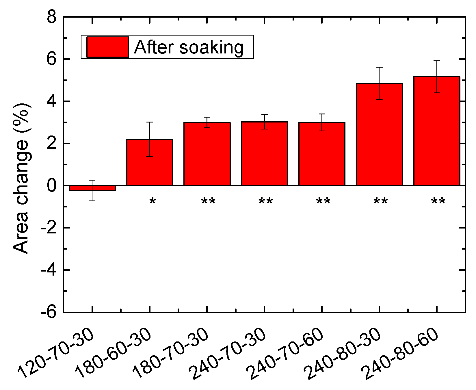
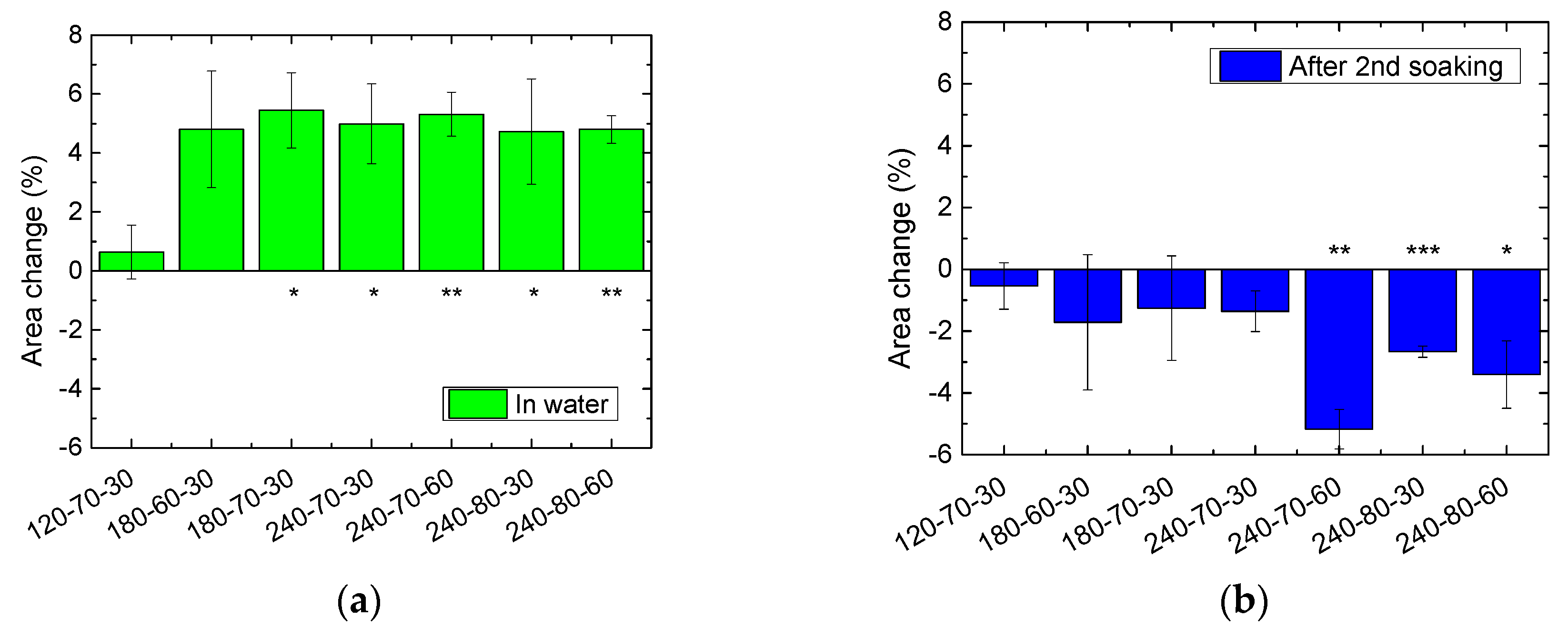
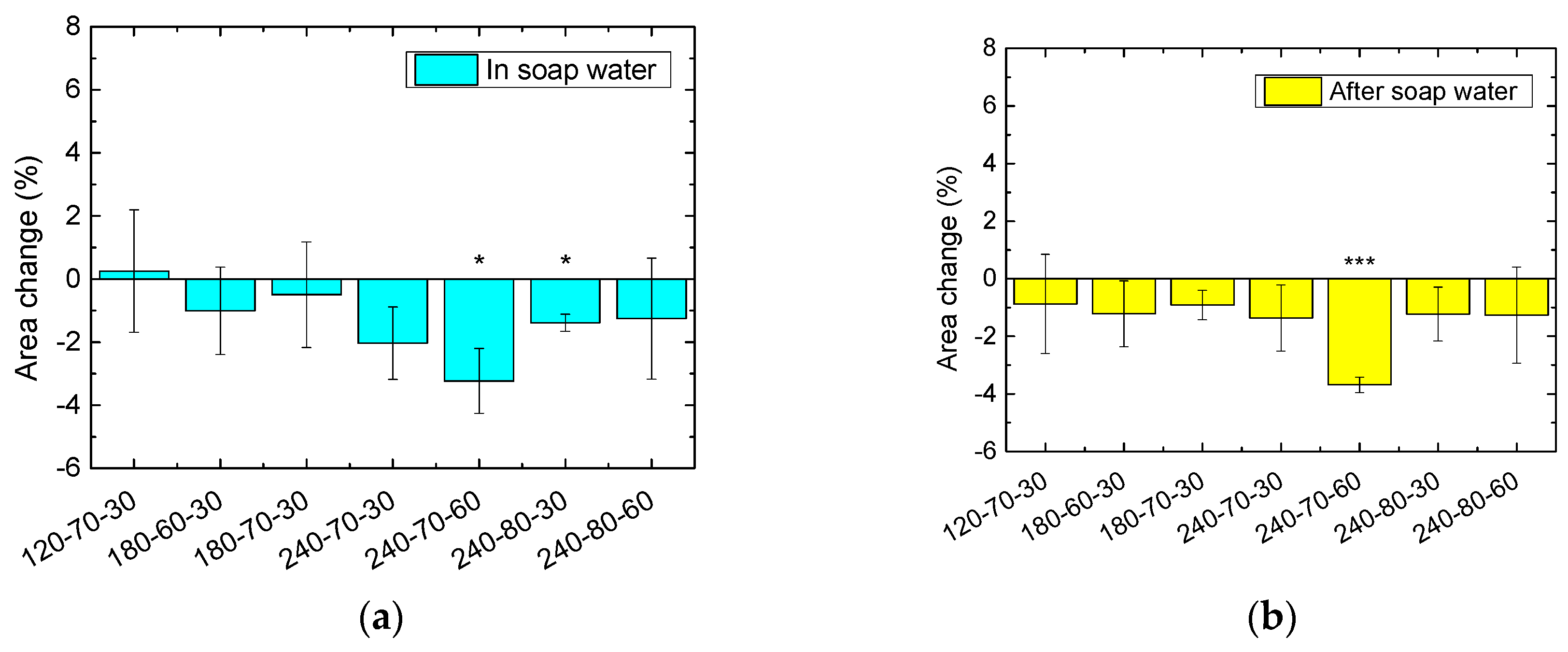
PAN solution was prepared with X-PAN (Dralon GmbH, Lingen, Germany) in a concentration of 16 wt% dissolved in DMSO (min. 99.9%, purchased from S3 Chemicals, Bad Oeynhausen, Germany) by stirring for two hours at room temperature. X-PAN consists of 93 % acrylonitrile (AN) and the co-monomers methyl acrylate (MA, 6%) and sodium 2-methyl-2-propene-1-sulfonic acid (Na-MAS, 0.5%).
Electrospinning was performed using a “Nanospider Lab” needleless electrospinning machine (Elmarco, Liberec, Czech Republic). The spinning parameters—voltage between both wires, electrode-substrate distance (E/S distance), and spinning duration—were varied for each nanofiber mat. The different combinations are shown in Table 1. These parameters were chosen as, according to previous experience, these combinations result in homogenous nanofiber mats [41]. The areal weights, averaged over 3 specimens per sample code, are discussed in the Results section.
The other spinning parameters are depicted in Table 2; they were kept constant as much as possible.
For the soaking process, the nanofiber mats were placed in petri dishes, and drops of pure/soap water were slowly added to avoid undesired crinkling of the samples (cf. Figure 2) until 10 mL pure water/ water with 3 drops of soap were reached. It should be mentioned that neither the amount of water, nor the number of soap drops, changed the findings as long as the samples were completely soaked and could freely “swim” in the fluid. After letting the nanofiber mats rest in the water for 3 min, the water was pipetted from the petri dishes, and the nanofiber mats were left to air dry. During this process, they were regularly detached from the bottom of the petri dishes to avoid undesired conglutinations.
The nanofiber mat morphologies were studied using: a VK-9000 (Keyence, Neu-Isenburg, Germany) confocal laser scanning microscope (CLSM) with a nominal magnification of 2000×; a scanning electron microscope (SEM) Zeiss 1450VPSE (Oberkochen, Germany) with a resolution of 5 nm and a nominal magnification of 5000; and an atomic force microscope (AFM) FlexAFM Axiom (Nanosurf, Liestal, Switzerland).
For measurements of the sample dimensions, an identical camera was placed at a defined distance from the samples, and images were taken using a rule for calibration. The images were evaluated using ImageJ 1.51j8 (National Institutes of Health, Bethesda, MD, USA). For statistical investigation, a one-sample t-test was performed.

3. Results

Figure 1 provides an overview of the morphologies of the nanofiber mats under examination. While electrospinning at the minimum distance of 120 mm between the electrodes with a voltage of 80 kV results in the creation of a nano-membrane with a non-fibrous structure [41] (i.e., of a single layer of several hundred nanometers to few micrometers thickness without visible fibers), this effect was avoided here by reducing the high voltage. Most of the nanofiber mats showed very similar morphologies, with the usual randomly oriented, interlaced fibers. Additional long straight fibers were visible only when using the combination of electrode distance 240 mm with a high voltage of 70 kV. Using 80 kV at a distance of 240 mm typically leads to the same thin and strongly interlaced fibers as in the other cases used here. This is due to higher voltages increasing the forces on the polymer fibers and reducing the time of flight between the high voltage electrode and the substrate—as smaller distances do—and thus the possibility to create thicker, longer fibers.
These small deviations are no longer visible when SEM images are depicted instead (Figure 2). On the arbitrarily chosen positions, the few long, straight fibers visible in Figure 1d cannot be recognized. The fiber morphologies are very similar for all samples; the amount of beads which typically occur in PAN nanofiber mats electrospun from DMSO [4] varies slightly not only between different samples, but also within the same sample, as depicted in Figure 3.
For a deeper investigation, Figure 3 depicts AFM images of the sample electrospun with 240 mm electrode distance and 80 kV voltage (cf. Figure 1e) [42]. Figure 3a,b show overviews of neighboring areas of side lengths 25 µm. Here the arbitrary distributions of fibers and beads are clearly visible, as is the broad distribution of fiber diameters. In both cases, a few relatively thick fibers are visible on the usual background of thinner fibers. Comparing different areas within these overview images also indicates that, on such small scales of several micrometers, the fiber and mat morphology differ strongly. This impedes a reliable “optical” investigation of the influence of wetting on the nanofiber mat morphology.
The same is visible comparing the smaller areas depicted in Figure 3c,d. While in both images areas without beads or large spaces between the fibers were investigated, the fiber diameters vary strongly; Figure 3c shows an area with several conglutinated fibers, while Figure 3d shows more fibers that are—either completely, or in parts of the image—separated and thus seemingly thinner.
These findings underline that small deviations after soaking the nanofiber mats in water or soap water cannot be expected to be visible in a fiber and mat morphology with such large deviations on the smallest scales. Thus, the quantitative description of the effect of wet relaxation on the nanofiber mats concentrates on a macroscopic measurement parameter, i.e., the sample dimension.
Table 1 depicts the areal weights of the different fabrics under examination. Firstly, the smallest distance results in the largest standard deviation, i.e., the strongest deviations between samples cut from different areas. This can be explained by fibers from one point of the high voltage wire reaching a larger fiber distribution area on the substrate, meaning that if the amount of spun polymer differs on different points of the wire, these deviations are leveled out for larger electrode-substrate distances. This also becomes visible by the significantly increased areal weight of sample 120-70-30, underlining that, for this short distance, electrospinning only occurred near the spinning wires.
The other correlations also show trends that are mostly expected. Doubling the spinning duration approximately doubles the areal weight of the nanofiber mat, and increasing the voltage also increases the areal weight for a 180 mm distance. For a distance of 240 mm, however, this behavior is different. Figure 1d suggests that for this combination of electrode distance and a solid content in the spinning solution of 16%, 70 kV is the ideal voltage, resulting in long, straight nanofibers and a larger areal weight compared to when using a voltage of 80 kV, as visible in Figure 1d.
Generally, PAN nanofiber mats show an interesting behavior when exposed to water. Figure 4a illustrates this effect. The left PAN nanofiber strip depicted here (taken from sample 240-80-30) is loaded with two strips of glue “green tape” to weigh it down; the middle one has similar dimensions without glue; the right one is more narrow. With the first contact to water, the middle nanofiber mat crinkled and folded, the right strip started to coil up (right strip). When this is prevented by a weight (left strip), the sides fold nevertheless.
Interestingly, a nanofiber mat exposed to water with soap behaves completely different (Figure 4b). In this case, the nanofiber strip stays completely straight and unfolded. This effect can either be explained by the significantly reduced water surface tension (approximately 55 mN/m for soap-water as opposed to 72 mN/m for pure water) or by the reduced static charges due to the surfactant. Electrospun nanofiber mats which are not finished to increase their conductivity always show a certain (typically positive) electrostatic charge as a result of the electrospinning process. This effect—which often makes handling of the nanofiber mats problematic—is significantly reduced after soaking a nanofiber mat in water with surfactant (typically negatively charged) and letting it dry. Independent from the reason why water with surfactant has a completely different impact on nanofiber mats than pure water, these preliminary tests indicate that both fluids should be investigated for the context of relaxation of electrospun nanofiber mats.
Firstly, all samples (three specimens each) were soaked in pure water. Figure 5 depicts the results. The percentage area change is calculated as the absolute area difference divided by the original area. Nearly all samples became larger; only the thickest sample 120-70-30 kept its area. It should be mentioned that the error bars are, in most cases, much smaller than the area change, indicating that the measured increase of the area is indeed significant. In addition, the level of statistical significance according to the one-sample t-test is given, as described in the figure caption.
Next, it was tested whether repeated soaking in water changes the dimensions of the nanofiber mats again, or whether one wet relaxation cycle is sufficient for complete relaxation, since both effects were reported for knitted fabrics [35,36,37,38,39]. Figure 6 shows the results of the second soaking process, investigated during soaking (Figure 6a) and after drying (Figure 6b).
The dimensions measured in water (Figure 6a) showed that all samples, aside from the one spun at the shortest distance, experienced an area change of approximately 5%. Comparing these values with those gained after the first soaking step indicates that a value of approximately 5% area increase may be consistent with a fully relaxed state, which may be reached after the first or the second wet relaxation step, depending on the spinning parameters.
After drying, however, something unexpected happened again (Figure 6b). All samples showed reduced areas. While this finding is not significant in all cases (cf. the large error bars for the first four samples), there is a clear deviation from both former findings.
In experiments with knitted fabrics, a higher level of relaxation is often reached for washing relaxation compared to wet relaxation; there is reduced friction due to surfactants, and, at the same time, energy barriers are overcome by the mechanical forces working on the fabrics [39,43]. While washing nanofiber mats in a household washing machine is not possible, the influence of surfactants may not only result in a stronger relaxation due to reduced fiber/fiber friction, but may also be of interest because of the aforementioned prevention of folding and creasing during exposure to water with surfactants.
Figure 7 depicts the dimensional changes during (a) and after soaking (b) the nanofiber mats in water with soap. Similar to the area changes shown in Figure 6b, most values here are negative, indicating a decrease of the sample areas. The further increased error bars result from the corners of some samples being folded erroneously during the tests, impeding exact measurements of the respective sample areas.
It should be mentioned that, starting from drying after the second soaking process, sample 240-70-60 always showed the largest decrease in sample area. This finding cannot be explained in terms of any special property of this sample. In addition, the differences are not significant, but merely a tendency. The difference between this sample and the others is given, on the one hand by the morphology (cf. Figure 1), and on the other hand by the thickness. However, the thinner sample with identical spinning parameters and thus same morphology—sample 240-70-30—does not show the same behavior, and neither does sample 240-80-60—the thicker one. More detailed investigations are further necessary to find out whether this tendency is a real effect or just an arbitrary one.

4. Discussion

The results of these wet relaxation tests cannot be interpreted straightforwardly. As opposed to investigations of the wet relaxation of knitted fabrics, a superposition of two opposing tendencies—shrinking and broadening—is observed.
A possible explanation for the first area increase may be found in the electrostatic charging of the single nanofibers in the mats; since they are all positively charged after the electrospinning process, they repel each other which may result in a macroscopically observable increase of the overall sample area. Deitzel et al. reported on a similar influence of the electrostatic charges of the nanofibers during electrospinning, leading to strong enough electrostatic forces to prevent fibers arriving later from being positioned on the first fibers [44]. Similarly, Li et al. used the positive charge of the nanofibers during electrospinning to orient them parallel on grounded electrodes [45]. Lee et al. used the positive electrostatic charge of electrospun nanofiber mats to graft negatively charged silica nanoparticles on them [46]. The impact of the residual charge after spinning on adjacent fibers, however, has not yet been taken into account. Sample 120-70-30 can be assumed to have most strongly connected fibers due to their reduced drying time on the shortest flight distance, possibly impeding displacements between fibers and thus area changes.
The electrostatic charge is not significantly influenced by pure water, as revealed by soaking samples in water several times and finding them still electrostatically charged afterwards. Thus the preserved area increase during the second soaking step seems logical. After drying, however, another mechanism counteracting the force increasing the sample area must be taken into account.
Comparing this problem with relaxation effects in knitted fabric suggests that a decrease in area may be attributed to a change in the shape; knitted fabrics would often become wider and thinner at the same time. Samples from the borders of the electrospinning area may show a certain degree of fiber orientation and could thus also reveal a certain anisotropy. Here, however, the ratio between the sample borders which are parallel vs. perpendicular to the spinning wires stays constant within measurement accuracy.
Generally, a decrease in the area must be correlated with either an increase in thickness or an increase in density. For the small deviations from the original dimensions which were measured here, however, both these parameters could not be measured with high enough precision, and thus cannot be used to gain further information about the relaxation processes in the nanofiber mats.
Finally, while the relaxation processes found here cannot be explained completely yet, it should be mentioned that further experimental examination is an important requirement for the creation of stable filter materials from nanofiber mats. This is especially so for those which may be mounted in any rigid frame, and will neither break due to too high relaxation forces, nor start folding due to relaxation processes increasing their areas. Investigations with a larger number of samples to reduce the measurement uncertainty, more spinning parameters (adding more distances, voltages and spinning durations), and other fluids with defined surface tensions to soak the sample in are necessary to reliably depict the influence of these parameters on nanofiber mat relaxation.

5. Conclusions

Wet relaxation tests were performed on electrospun nanofiber mats. The results show that for the nanofiber mats soaked in pure water, dimensions first increase up to 5%, but start decreasing after the second drying step following the second soaking process. Conversely, they always show a slight (mostly insignificant) areal decrease during and after soaking in soap water.
These preliminary findings show the importance of performing a larger study to give reliable dependencies of the wet relaxation on the spinning parameters, especially for the application of nanofiber mats as filter materials.

Author Contributions

Conceptualization, all authors; methodology, all authors; validation, all authors; investigation, T.G. and L.S.; writing—original draft preparation, T.G. and A.E.; writing—review and editing, all authors.

Funding

This research was partly funded by HiF fund of Bielefeld University of Applied Sciences.

Acknowledgments

We would like to thank Dralon GmbH for donating us the X-PAN material used in this study. We acknowledge the financial support of the German Research Foundation (DFG) and the Open Access Publication Fund of Bielefeld University of Applied Sciences for the Article Processing Charge.

Conflicts of Interest

The authors declare no conflict of interest.

References

  1. Greiner, A.; Wendorff, J.H. Electrospinning: A fascinating method for the preparation of ultrathin fibers. Angew. Chem. Int. Ed. 2007, 46, 5670–5703. [Google Scholar] [CrossRef] [PubMed]
  2. Salalha, W.; Dror, Y.; Khalfin, R.; Cohen, Y.; Yarin, A.L.; Zussman, E. Single-Walled Carbon Nanotubes Embedded in Oriented Polymeric Nanofibers by Electrospinning. Langmuir 2004, 20, 9852–9855. [Google Scholar] [CrossRef] [PubMed]
  3. Liu, H.H.; Li, Y.J.; Yuan, M.W.; Sun, G.B.; Liao, Q.L.; Zhang, Y. Solid and macroporous Fe3C/N-C nanofibers with enhanced electromagnetic wave absorbability. Sci. Rep. 2018, 8, 16832. [Google Scholar] [CrossRef] [PubMed]
  4. Döpke, C.; Grothe, T.; Steblinski, P.; Klöcker, M.; Sabantina, L.; Kosmalska, D.; Blachowicz, T.; Ehrmann, A. Magnetic Nanofiber Mats for Data Storage and Transfer. Nanomaterials 2019, 9, 92. [Google Scholar] [CrossRef] [PubMed]
  5. Pakravan, M.; Heuzey, M.-C.; Ajji, A. A fundamental study of chitosan/PEO electrospinning. Polymer 2011, 52, 4813–4824. [Google Scholar] [CrossRef]
  6. Wongchitphimon, S.; Wang, R.; Jiraratananon, R.; Shi, L.; Loh, C.H. Effect of polyethylene glycol (PEG) as an additive on the fabrication of polyvinylidene fluoride-co-hexafluropropylene (PVDF-HFP) asymmetric microporous hollow fiber membranes. J. Memb. Sci. 2011, 369, 329–338. [Google Scholar] [CrossRef]
  7. Grothe, T.; Wehlage, D.; Böhm, T.; Remche, A.; Ehrmann, A. Needleless electrospinning of PAN nanofibre mats. Tekstilec 2017, 60, 290–295. [Google Scholar] [CrossRef]
  8. Manoharan, M.P.; Sharma, A.; Desai, A.V.; Haque, M.A.; Bakis, C.E.; Wang, K.W. The interfacial strength of carbon nanofiber epoxy composite using single fiber pullout experiments. Nanotechnology 2009, 20, 5. [Google Scholar] [CrossRef]
  9. Ji, L.W.; Yao, Y.F.; Toprakci, O.; Lin, Z.; Liang, Y.Z.; Shi, Q.; Medfort, A.J.; Millns, C.R.; Zhang, X.W. Fabrication of carbon nanofiber-driven electrodes from electrospun polyacrylonitrile/polypyrrole bicomponents for high-performance rechargeable lithium-ion batteries. J. Power Sources 2010, 195, 2050–2056. [Google Scholar] [CrossRef]
  10. Jung, H.R.; Lee, W.J. Preparation and characterization of Ni-Sn/carbon nanofibers composite anode for lithium ion battery. J. Electrochem. Soc. 2011, 158, A644–A652. [Google Scholar] [CrossRef]
  11. Liu, J.W.; Essner, J.; Li, J. Hybrid supercapacitor based on coaxially coated manganese oxide on vertically aligned carbon nanofiber arrays. Chem. Mater. 2010, 22, 5022–5030. [Google Scholar] [CrossRef]
  12. Schnell, E.; Klinkhammer, K.; Balzer, S.; Brook, G.; Klee, D.; Dalton, P.; Mey, J. Guidance of glial cell migration and axonal growth on electrospun nanofibers of poly-epsilon-caprolactone and a collagen/polyepsilon-caprolactone blend. Biomaterials 2007, 28, 3012–3025. [Google Scholar] [CrossRef] [PubMed]
  13. Großerhode, C.; Wehlage, D.; Grothe, T.; Grimmelsmann, N.; Fuchs, S.; Hartmann, J.; Mazur, P.; Reschke, V.; Siemens, H.; Rattenholl, A.; et al. Investigation of microalgae growth on electrospun nanofiber mats. AIMS Bioeng. 2017, 4, 376–385. [Google Scholar] [CrossRef]
  14. Wang, L.; Zhang, C.; Gao, F.; Pan, G. Needleless electrospinning for scaled-up production of ultrafine chitosan hybrid nanofibers used for air filtration. RSC Adv. 2016, 6, 105988–105995. [Google Scholar] [CrossRef] [Green Version]
  15. Zhao, X.; Liu, Y.; Wang, C.; Liu, Q.S. Structure and filtration performance of fibrous composite membranes containing environmentally friendly materials for water purification. Fiber Polym. 2015, 16, 2586–2592. [Google Scholar] [CrossRef]
  16. Ferrero, F.; Periolatto, M.; Vineis, C.; Varesano, A. Chitosan coated cotton gauze for antibacterial water filtration. Carbohyd. Polym. 2014, 103, 207–212. [Google Scholar] [CrossRef] [PubMed]
  17. Roche, R.; Yalcinkaya, F. Incorporation of PVDF Nanofibre Multilayers into Functional Structure for Filtration Applications. Nanomaterials 2018, 8, 771. [Google Scholar] [CrossRef]
  18. Cooper, A.; Oldinski, R.; Ma, H.Y.; Bryers, J.D.; Zhang, M.Q. Chitosan-based nanofibrous membranes for antibacterial filter applications. Carbohyd. Polym. 2013, 92, 254–259. [Google Scholar] [CrossRef] [Green Version]
  19. Vasilyev, G.; Burman, M.; Arinstein, A. Estimating the Degree of Polymer Stretching during Electrospinning: An Experimental Imitation Method. Macromol. Mater. Eng. 2017, 302, 1600554. [Google Scholar] [CrossRef]
  20. Arinstein, A.; Zussman, E. Electrospun polymer nanofibers: Mechanical and thermodynamic perspectives. J. Polym. Sci. Part B Polym. Phys. 2011, 49, 691–707. [Google Scholar] [CrossRef] [Green Version]
  21. Ramachandramoorthy, R.; Beese, A.; Espinosa, H. In situ electron microscopy tensile testing of constrained carbon nanofibers. Int. J. Mech. Sci. 2018, 149, 452–458. [Google Scholar] [CrossRef]
  22. Munajat, N.A.; Nurfaizey, A.H.; Bahar, A.A.M.; You, K.Y.; Fadzullah, S.H.S.M.; Omar, G. High-frequency dielectric analysis of carbon nanofibers from PAN precursor at different pyrolysis temperatures. Microw. Opt. Technol. Lett. 2018, 60, 2198–2204. [Google Scholar] [CrossRef]
  23. Alarifi, I.M.; Khan, W.S.; Asmatulu, R. Synthesis of electrospun polyacrylonitrile-derived carbon fibers and comparison of properties with bulk form. PLoS ONE 2018, 13, e0201345. [Google Scholar] [CrossRef] [PubMed]
  24. Barua, B.; Saha, M.C. Studies of reaction mechanisms during stabilization of electrospun polyacrylonitrile carbon nanofibers. Polym. Eng. Sci. 2018, 58, 1315–1321. [Google Scholar] [CrossRef]
  25. Zhao, X.; Ma, X.F.; Zheng, P.W. The preparation of carboxylic-functional carbon-based nanofibers for the removal of cationic pollutants. Chemosphere 2018, 202, 298–305. [Google Scholar] [CrossRef] [PubMed]
  26. Ma, S.; Liu, J.; Liu, Q.; Liang, J.Y.; Zhao, Y.; Fong, H. Investigation of structural conversion and size effect from stretched bundle of electrospun polyacrylonitrile copolymer nanofibers during oxidative stabilization. Mater. Des. 2016, 95, 387–397. [Google Scholar] [CrossRef]
  27. Wu, S.; Zhang, F.; Yu, Y.H.; Li, P.; Yang, X.P.; Lu, J.G.; Rye, S.K. Preparation of PAN-based carbon nanofibers by hot-stretching. Compos. Interfaces 2008, 15, 671–677. [Google Scholar] [CrossRef]
  28. Xie, Z.; Niu, H.; Lin, T. Continuous polyacrylonitrile nanofiber yarns: Preparation and drydrawing treatment for carbon nanofiber production. RSC Adv. 2015, 5, 15147–15153. [Google Scholar] [CrossRef]
  29. Ma, S.; Liu, J.; Qu, M.; Wang, X.; Huang, R.; Liang, J. Effects of carbonization tension on the structural and tensile properties of continuous bundles of highly aligned electrospun carbon nanofibers. Mater. Lett. 2016, 183, 369–373. [Google Scholar] [CrossRef]
  30. Santos de Oliveira, M., Jr.; Manzolli Rodrigues, B.V.; Marcuzzo, J.S.; Guerrini, L.M.; Baldan, M.R.; Rezende, M.C. A statistical approach to evaluate the oxidative process of electrospun polyacrylonitrile ultrathin fibers. J. Appl. Polym. Sci. 2017, 134, 45458. [Google Scholar] [CrossRef]
  31. Wu, M.; Wang, Q.Y.; Li, K.; Wu, Y.Q.; Liu, H.Q. Optimization of stabilization conditions for electrospun polyacrylonitrile nanofibers. Polym. Degrad Stab. 2012, 97, 1511–1519. [Google Scholar] [CrossRef]
  32. Sabantina, L.; Klöcker, M.; Wortmann, M.; Rodrígues-Mirasol, J.; Cordero, T.; Moritzer, E.; Finsterbusch, K.; Ehrmann, A. Stabilization of PAN nanofiber mats obtained by needleless electrospinning using DMSO as solvent. J. Ind. Text. 2019. [Google Scholar] [CrossRef]
  33. Sabantina, L.; Wehlage, D.; Klöcker, M.; Mamun, A.; Grothe, T.; Rodrígues-Mirasol, J.; Cordero, T.; Finsterbusch, K.; Ehrmann, A. Stabilization of electrospun PAN/gelatin nanofiber mats for carbonization. J. Nanomater. 2018, 2018, 6131085. [Google Scholar] [CrossRef]
  34. Sabantina, L.; Rodríguez-Cano, M.A.; Klöcker, M.; García-Gateos, F.J.; Ternero-Hidalgo, J.J.; Mamun, A.; Beermann, F.; Schwakenberg, M.; Voigt, A.-L.; Rodríguez-Mirasol, J.; et al. Fixing PAN nanofiber mats during stabilization for carbonization and creating novel metal/carbon composites. Polymers 2018, 10, 735. [Google Scholar] [CrossRef]
  35. Quaynor, L.; Nakajima, M.; Takahashi, M. Dimensional changes in knitted silk and cotton fabrics with laundering. Text. Res. J. 1999, 69, 285–291. [Google Scholar] [CrossRef]
  36. Quaynor, L.; Takahashi, M.; Nakajima, M. Effects of laundering on bending properties of plain-knitted fabrics. J. Text. Mach. Soc. Jpn. (Engl. Ed.) 1998, 44, 74–77. [Google Scholar] [CrossRef]
  37. Chen, Q.H.; Au, K.F.; Yuen, C.W.M.; Yeung, K.W. Dimensional stability of plain wool knits. Text. Asia 2000, 31, 51–57. [Google Scholar]
  38. Knapton, J.J.F.; Ahrens, F.J.; Ingenthron, W.W.; Fong, W. The dimensional properties of knitted wool fabrics, Part I: The plain-knitted structure. Text. Res. J. 1968, 10, 999–1012. [Google Scholar] [CrossRef]
  39. Ehrmann née Tillmanns, A.; Heimlich, F.; Brücken, A.; Weber, M.O.; Blachowicz, T. Experimental investigation of the washing relaxation of knitted fabrics from polyester yarn with stainless steel fibres. Fibres Text. East. Eur. 2012, 20, 90–93. [Google Scholar]
  40. Bahl, O.P.; Shen, Z.M.; Lavin, J.G.; Ross, R.A. Manufacture of Carbon Fibers. In Carbon Fibers, 3rd ed.; Donnet, J.-B., Wang, T.K., Peng, J.C.M., Rebouillat, S., Eds.; CRC Press, Taylor & Francis Group: Boca Raton, FL, USA; London, UK; New York, NY, USA, 1998. [Google Scholar]
  41. Sabantina, L.; Hes, L.; Rodríguez-Mirasol, C.T.; Ehrmann, A. Water vapor permeability through PAN nanofiber mat with varying membrane-like areas. Fibres Text. East. Eur. 2019, 133, 12–15. [Google Scholar] [CrossRef]
  42. Döpke, C.; Juhász Junger, I.; Steblinski, P.; Ehrmann, A.; Blachowicz, T. Electrospinning Magnetic Nanofibers for Neuromorphic Computing. Int. Fiber J. 2018, 2018, 37–39. [Google Scholar]
  43. Gsell, E.; Heimlich, F.; Ehrmann, A.; Weber, M.O. Dependence of dry, wet and washing relaxation on knitted structures and fabric parameters. Ind. Text. 2017, 68, 121–125. [Google Scholar]
  44. Deitzel, J.M.; Kleinmeyer, J.; Harris, D.; Beck Tan, N.C. The effect of processing variables on the morphology of electrospun nanofibers and textiles. Polymer 2001, 42, 261–272. [Google Scholar] [CrossRef]
  45. Li, D.; Wang, Y.L.; Xia, Y.N. Electrospinning of Polymeric and Ceramic Nanofibers as Uniaxially Aligned Arrays. Nano Lett. 2003, 3, 1167–1171. [Google Scholar] [CrossRef]
  46. Lee, J.H.; Boo, C.H.; Ryu, W.H.; Taylor, A.D.; Elimelech, M. Development of Omniphobic Desalination Membranes Using a Charged Electrospun Nanofiber Scaffold. ACS Appl. Mater. Interfaces 2016, 8, 11154–11161. [Google Scholar] [CrossRef] [PubMed]
Figure 1. Confocal laser scanning microscope (CLSM) images of electrospun polyacrylonitrile (PAN) nanofiber mats with different spinning parameters (electrode-substrate distance/voltage): (a) 120 mm/70 kV; (b) 180 mm/60 kV; (c) 180 mm/70 kV; (d) 240 mm/70 kV; (e) 240 mm/80 kV. All spinning durations were 30 min.
Technologies 07 00023 g001
Figure 2. SEM images of electrospun PAN nanofiber mats with different spinning parameters (electrode-substrate distance/voltage): (a) 120 mm/70 kV; (b) 180 mm/60 kV; (c) 180 mm/70 kV; (d) 240 mm/70 kV; (e) 240 mm/80 kV. All spinning durations were 30 min.
Technologies 07 00023 g002
Figure 3. AFM images of electrospun PAN nanofiber mats with spinning parameters 240 mm/80 kV, corresponding to Figure 1e, taken on different positions (a,b) with a side length of 25 µm; (c,d) with a side length of 6.25 µm. (a) from [42], modified.
Technologies 07 00023 g003
Figure 4. Electrospun PAN nanofiber mats (a) after being exposed to water; (b) after being exposed to water with soap.
Technologies 07 00023 g004
Figure 5. Percentage change of the areas of the electrospun PAN nanofiber mats after exposure to pure water. Statistical significance is depicted by * (p < 0.05) or ** (p < 0.01), respectively.
Technologies 07 00023 g005
Figure 6. Percentage change of the areas of the electrospun PAN nanofiber mats (a) during exposition to water; (b) after exposure to water and drying. Statistical significance is depicted by * (p < 0.05), ** (p < 0.01) or *** (p < 0.002), respectively.
Technologies 07 00023 g006
Figure 7. Percentage change of the areas of the electrospun PAN nanofiber mats (a) during exposition to water with soap; (b) after exposition to soap water and drying. Statistical significance is depicted by * (p < 0.05), ** (p < 0.01) or *** (p < 0.002), respectively.
Technologies 07 00023 g007
Table 1. Parameter combinations for the electrospinning process.
Sample CodesE/S Distance (mm)Voltage (kV)Spinning Duration (min)Areal Weight (g/m²)
120-70-30120703028 ± 4
180-60-3018060309.5 ± 0.7
180-70-30180703011.3 ± 1.0
240-70-3024070304.1 ± 0.3
240-70-6024070608.6 ± 0.5
240-80-3024080303.2 ± 0.3
240-80-6024080606.2 ± 0.9
Table 2. Spinning parameters.
ParameterValue
Current (mA)0.06–0.09
Nozzle diameter (mm)0.9
Carriage speed (mm/s)100
Substrate speed (mm/min)0
Ground-substrate distance (mm)50
Temperature in chamber (°C)21–23
Relative humidity in chamber (%)31–33

