1. Introduction
The number of objects connected to the cloud is expected to rise dramatically in the next years [
1]. Existing algorithms are not ready for the machine-type, ultra-low latency, and dense object connectivity requirements of 5G [
2]. The dedicated allocation algorithms of 3G/4G have been proven useful in settings with long, high-rate sessions and finite numbers of simultaneous requests. This is a disadvantage for industrial connectivity, where a large number of simultaneous short (bursty) sessions can arise. To address these issues, random access protocols turn out to be ideal for bursty traffic sources by showing low latency and reduced complexity. The disadvantage occurs with long sessions or high loads. However, the last few decades have witnessed improvements in random access that can overcome these problems and thus, make this type of protocols a good candidate for 5G.
Multi-packet reception (MPR) is one of the main candidates to improve the performance of random access protocols [
3,
4,
5]. MPR algorithms have been analyzed extensively using multiple antennas, frequency resources or power capture, to name a few. However, the performance of random access with MPR declines when the
fixed MPR capacity is surpassed by the number of simultaneous connection requests. A breakthrough in the literature of signal-processing-assisted random access protocols was presented in [
6] where the authors use an adaptive source of diversity via retransmissions to achieve MPR. The algorithm was called NDMA or network diversity multiple access, and in ideal conditions it can achieve almost collision free performance, ultra low latency, and minimum feedback complexity. These features are very attractive for contention-based access in 5G. In NDMA, the MPR capabilities are adaptive and therefore, the algorithm can deal, in principle, with collisions of any size. NDMA is the perfect example of cross-layer algorithm: retransmissions induced by MAC (medium access control) layer create a source of physical (PHY)-layer diversity to resolve a collision.
In NDMA, the Base Station (BS) uses signal-processing to estimate the size of a collision. This is used to calculate the number of retransmissions required to achieve MPR and recover the colliding signals (i.e., resolve the collision). Retransmissions are stored in memory and the BS uses MIMO (multiple-input multiple-output) tools to recover and decode the signals in conflict. Training-based versions of NDMA have been proposed in non-dispersive and dispersive channels in [
6,
7], respectively. Blind versions can be found in [
8,
9]. Stability analysis with perfect channel and reception conditions were presented in [
10]. NDMA with MPR has been investigated in [
11] using Markov chains improving data rates and delay. In our work in [
12] an addition to NDMA-MPR based on Successive Interference Cancellation (SIC) was shown to surpass the capacity of previous protocols. Hybrid combination of NDMA with Automatic Repeat reQuest (ARQ) was presented in [
13]. Feedback free NDMA was presented in [
14], and an asynchronous blind NDMA was recently presented in [
15]. NDMA with sequential detection and non-orthogonal sequences was presented in [
16].
This paper is the extension of [
2], comprising MPR capabilities in Rice fading correlated channels with co-channel interference. This is the first attempt to investigate the effects of line-of-sight (LOS) and co-channel interference in NDMA. The original work in [
2] extends the NDMA protocol expressions to include backlog retransmission of collisions that remain unresolved. Two strategies were implemented:
persistent and
randomized retransmission schemes. In the persistent retransmission approach, signals involved in an unsuccessful collision resolution period reattempt transmission immediately in a new resolution period generating an identical collision event but with different channel conditions. The process is repeated until the original collision is resolved. In the case of the randomized strategy, the signals involved in an unsuccessful collision resolution period retransmit at a randomly selected resolution period, thus, creating different randomized collision events in future resolution periods. All protocol expressions have been upgraded to reflect the new settings with spatial correlation, multiple antenna reception, and co-channel interference. The results show that NDMA surpasses by a significant margin its ALOHA counterparts, and when the SNR (signal-to-noise ratio) is high enough and with moderate traffic loads, low latency values and high throughput performance could be attractive for future 5G networks. Summarizing, the achievements of this paper are as follows:
Extension of NDMA-MPR to Correlated Rice channels.
Analysis of backlog retransmission strategies.
Analysis of NMDA detection protocol with co-channel interference.
The organization of this paper is as follows.
Section 2 presents the system assumptions.
Section 5 presents the details of the first retransmission strategy (also called here persistent retransmission strategy).
Section 6 details the random retransmission strategy. Results of the retransmission schemes are displayed and discussed in
Section 7. The conclusions of the paper are then presented in
Section 8.
Notation: lower case bold letters denote vector variables and upper case bold letters denote matrix variables. is the statistical average operator, is the average of random variable x conditional on a particular instance of random variable y, is the statistical average operation over the random variable x, is the complement to one operator (i.e., for any a), is the combinatorial number of elements (objects) in positions, is the characteristic function of random variable x, and is the frequency domain variable. denotes the identity matrix of order Q, is the column vector of size with all elements equal to zero, and is the column vector of size with all elements equal to 1. is the Hermitian vector transpose operator and is the vector transpose operator.
2. System Model and Assumptions
2.1. Scenario Description and NDMA Protocol Operation
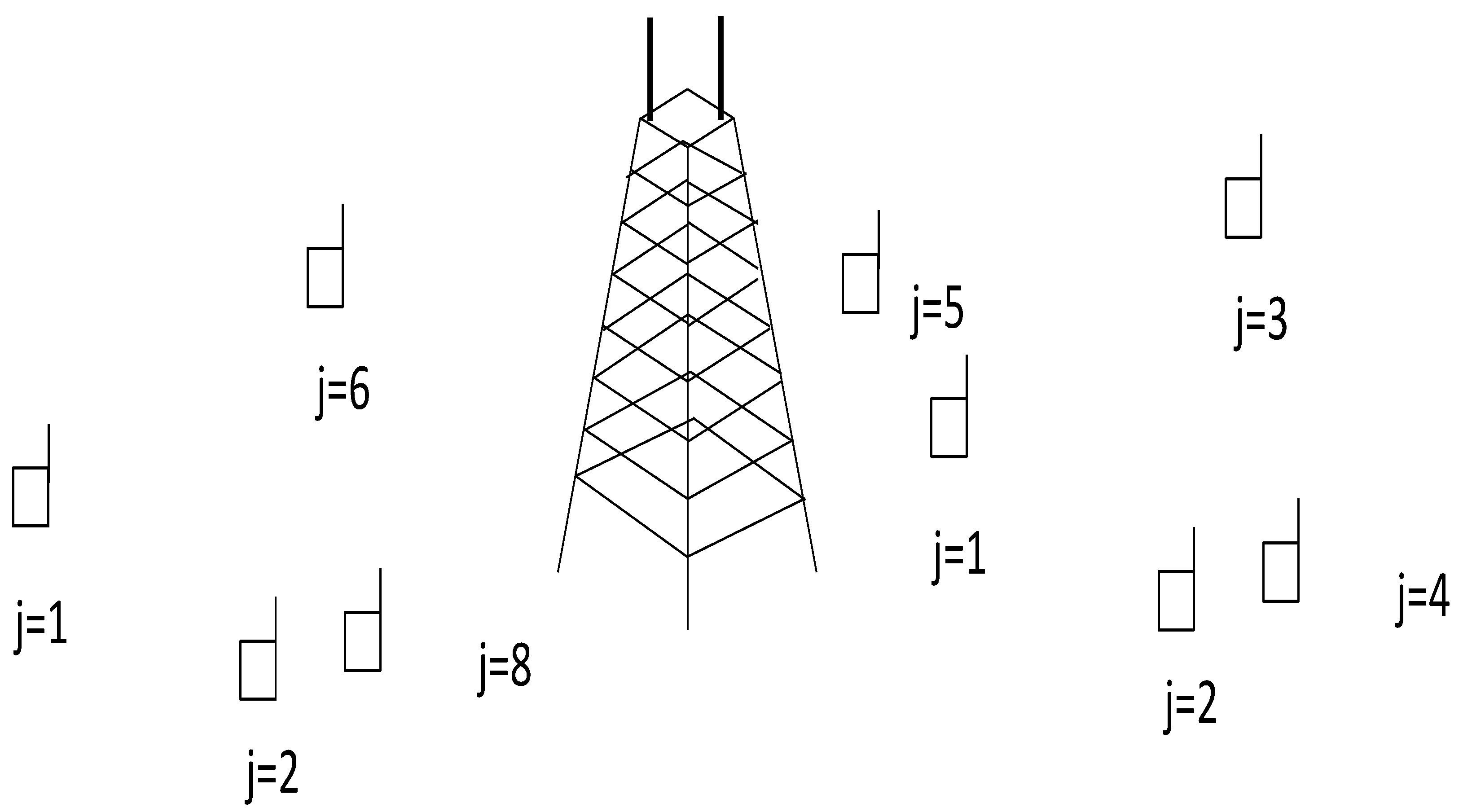
Consider the wireless random access network depicted in
Figure 1 with one base station (BS) enabled with
receiving antennas and
one-antenna terminals. Each terminal is assumed to have a buffer experiencing a packet arrival process with Poisson statistics described by the parameter
. The transmission probability of any terminal at the beginning of any resolution period is denoted by
. The channel between terminal
and the
th antenna of the BS is assumed to be non-dispersive, block fading and independently distributed with Rice envelope statistics:
, where
is the line-of-sight (LOS) component and
is the variance of the random component. The channel model can be rewritten for convenience as follows:
where
. Channels will be correlated in space:
, where
is the complex conjugate operator,
is the statistical average operator, and
is the correlation coefficient between the signal of antenna
with the signal of antenna
. All channels can be thus, generated using a generalized linear correlation model given by:
where the variables
and
are independent circular complex Gaussian random variables with zero mean and variance
.
Whenever the terminals are allowed to transmit a packet, they do so at the beginning of a new collision resolution period or epoch-slot. At the beginning of every epoch slot, the BS proceeds to obtain an estimate of the identity of the colliding terminals by means of signal-processing tools (details can be found in [
6] and later in this paper). Each terminal uses (as packet header) an orthogonal code previously assigned. The BS exploits this header using a matched filter receiver and energy detection processing to estimate the presence of each terminal in the collision event. Since this process is prone to errors due to fading and noise, the conditional probability of detection given that the terminal has transmitted a packet in the current time-slot is given by
(probability of correct presence detection). On the other hand, the conditional probability of presence detection given that the terminal did not engaged transmission is given by
or probability of false alarm.
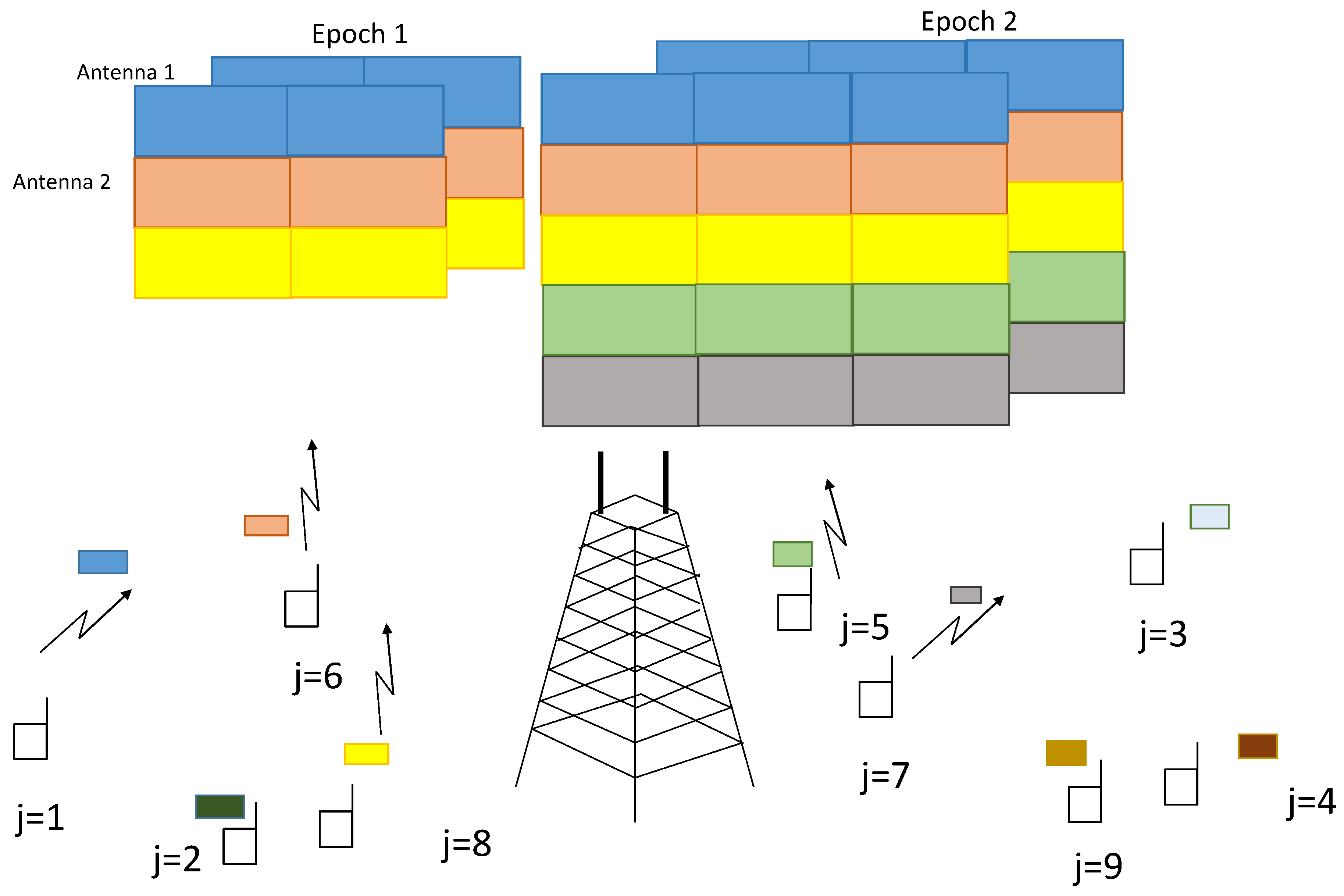
The detection of the presence of the different active terminals provides an estimation of the collision size. Based on this information, the BS proceeds to request retransmissions from the contending terminals so as to construct a virtual Multiple-Input Multiple-Output (MIMO) system with the convenient rank conditions that will ensure that the collision can be resolved. The conventional NDMA retransmission process in ideal detection settings with two collision resolution periods is displayed in
Figure 2. The main principle of retransmission diversity is that terminals transmit in consecutive time slots. Different packet transmissions of different terminals are shown in different colours in
Figure 2. The first epoch shows three terminals colliding in the first time slot of epoch 1, and one more retransmission is necessary to have the necessary degrees of freedom (
antennas and two time slots) to resolve the collision of three signals. The second epoch deals with a collision of five terminals in two time slots with
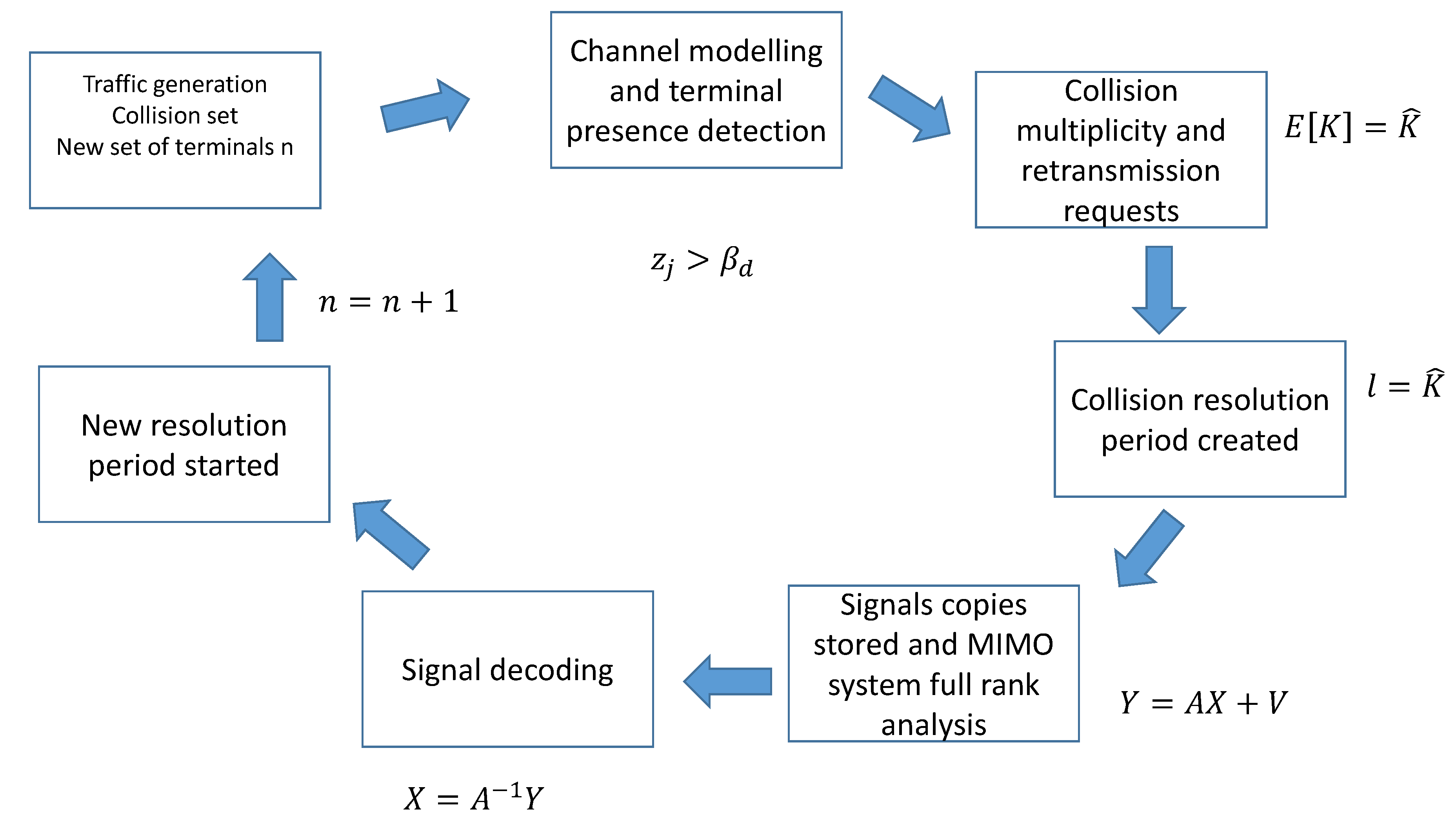
antennas. The collision resolution process of NDMA is also explained in block diagram in
Figure 3.
All signal-processing stages are prone to errors, so there will be cases where the collision is not resolved correctly or remaining decoding errors need to be controlled. Backlog retransmission strategies are therefore, necessary to recover the information lost in previous collision events.
2.2. Backlog Retransmission Schemes
In NDMA, it is conventionally assumed that any detection error at the BS side yields the loss of all packets involved in the collision. Conversely, the collision is successfully resolved only when all the terminals are correctly detected (both active and idle terminals). This paper proposes two backlog retransmission schemes to deal with the packets that were involved in an unsuccessful collision resolution period. The first scheme (also called persistent) allows the colliding terminals to engage immediately in a new resolution period. The BS indicates to the terminals that the previous resolution process did not succeed, and therefore, the same set of colliding terminals transmit again at the beginning of the new resolution period. This procedure is repeated until all the packets involved in the collision are correctly decoded by the destination.
In the second retransmission strategy, the backlogged terminal retransmits randomly in a future epoch slot with probability , which is exactly the same probability as the overall system attempt rate. This scheme is also called random retransmission scheme.
2.3. Epoch-Slot Definition and Feedback Flags
The collision multiplicity at the beginning of any epoch slot will be denoted by the random variable . The length of a simple collision resolution period will be denoted by the random variable . The period of time used for a packet to be correctly decoded by the BS will be denoted by , and it will be called super-epoch. Two types of epoch and super-epoch are defined: relevant, where a particular terminal under analysis is always present, and irrelevant, where such an incumbent terminal is idle.
The BS has two binary feedback flags that are considered to be ideal and instantaneous. One flag is used to indicate to the colliding terminals that retransmission is needed in the next time slot for purposes of diversity. The second feedback flag occurs at the end of a collision resolution period and indicates whether the epoch was successful or not. Based on this information, the colliding terminals decide to enter in one of the backlog retransmission schemes presented in this paper.
2.4. Examples
To further illustrate the proposed algorithms,
Figure 4 shows the realization of the two retransmission strategies over 4 epoch-slots. In the first epoch (
) of retransmission strategy 1, four terminals collide at the beginning of the epoch slot. However, only two of them were detected correctly as active ({2,8}). The system has requested no more retransmissions when indeed it was necessary to collect one more retransmissions to obtain a total of 4 degress of freedom to resolve a collision of size
. This means this epoch
is unsuccessful. The terminals are now in backlog state and retransmit immediately in the next resolution period. Once again, the detection process was incorrect, by miss-detecting three of the contending terminals ({1,2,3}) and estimating two of the idle terminals ({4,5}) as active (false alarm). The backlogged terminals proceed then to retransmit again in a third consecutive epoch slot (
). This time all terminals were correctly detected, one retransmission is requested, and the collision is conveniently resolved. The fourth epoch (
) allows new terminals to transmit, and it can be observed that this case was a successful epoch. Note that the first collision took three epoch slots to be correctly resolved with total length of
. This set of epoch slots that a collision experiences to be resolved is called
super epoch.
In the second retransmission strategy in
Figure 5, the four contending terminals involved in the first resolution period become backlogged. However, they start retransmission randomly over the next epoch slots. In the second epoch slot, terminal
retransmits the backlogged packet and this time the resolution is successful. By contrast, the third epoch sees terminal
to experience again an incorrect detection with one case of false alarm. The last epoch shows that two non-backlogged terminals experience a successful collision resolution. Note that the super-epoch for terminal
is given by the first and second resolution periods with a total length of
.
3. Signal Model
Each terminal is pre-assigned with an orthogonal code consisting of
symbols:
. This code is attached as header of each packet transmission of terminal
, and is employed for purposes of presence detection (collision multiplicity estimation) and channel estimation. The orthogonality condition of the set of codes is given by:
. The received signal in antenna
coming from all the headers of the set of colliding terminals (denoted here by
) can be written as:
where
is the interference term modelled as a circular Gaussian variable that remains constant along the transmitted header:
and
is the zero-mean and white complex Gaussian noise vector in the header with variance
. This means that
. The BS uses a matched-filter operation (
) to extract the presence information of each terminal
. The result is computed as follows:
The presence detection variable
for terminal
in (
4) is compared to a detection threshold
to decide whether terminal
is present or not in the collision. If
, then terminal
is considered as inactive or not present in the collision:
, where
is the estimated set of contending terminals. Otherwise, if
, then terminal
is considered as active or present in the collision (
). The estimated set of contending terminals can be therefore, defined as the set
of all the terminals whose detection variable
exceeds the detection threshold:
. Since this detection process is prone to errors due to channel fading and noise, two conditional presence detection cases can be identified: (1) terminal
can be correctly detected as active with probability
provided the terminal has transmitted a packet, and (2) terminal
is incorrectly detected as active with probability
(probability of false alarm) provided the terminal did not transmit a packet. By detecting the presence of each one of the contending terminals, the BS also has an estimation
of the collision multiplicity
, where,
is the estimated number of contending signals, and
is the number of contending signals.
The BS proceeds to request the estimated retransmissions
considering the number of degrees of freedom. The signal model for all the received signals in time slot
of a collision resolution period is given by:
where
is the signal vector received in time slot
,
is the transmitted signal vector by terminal
(
), and
is the interference vector in time-slot
. The signals are stored in memory after each retransmission and they can be arranged in a linear MIMO (multiple-input multiple output) model as follows:
where
is the stacked received signals across all time-slots of the resolution period and the antennas of the BS,
is the composite MIMO channel,
is the matrix of stacked colliding signals,
is the interference term, and
is the white Gaussian noise. The original signals can then be recovered using ZF, i.e., zero-forcing, (
) or minimum mean square error (MMSE) detection (
). Each signal will experience a post-processing signal-to-interference-plus-noise ratio (SINR) denoted by
. The packet can be considered to be correctly received by the destination when this post-processing SINR surpasses a given threshold.
4. Receiver Operational Characteristic (ROC) for Terminal Presence Detection
NDMA highly depends on the performance of the terminal presence detector. Any detection error, usually leads either to the loss of a significant percentage of the colliding signals in case of underestimation of collision multiplicity, or to the waste of transmission resources in case of overestimation of the collision size. This section deals with the statistical modelling of the terminal presence detector in (
4). This will be useful for subsequent calculations and design of the MAC layer. The probability of false alarm of a terminal that did not transmit a signal while still being detected as active can be defined more formally as follows:
which is the probability that the detection variable
exceeds the detection threshold
, conditional on terminal
not being one of the contending terminals. Since the noise is Gaussian distributed, the detection variable
in (
4) follows a central chi-square distribution, and therefore, the probability of false alarm can be expressed in closed-form [
6] as:
Similarly, the probability of detection of terminal
, conditional on terminal
being one of the contending terminals can be defined as:
Since both channel and noise components are Gaussian distributed with mean
, the detection variable
in (
4) also follows a non-central chi-square distribution. The conditional characteristic function of the terminal presence indicator
can be proved to be:
where
. The unconditional CF can be obtained by averaging the previous expression over the PDF of the random variables
.Using numerical methods for the integration,
can be obtained as the complementary cumulative distribution function:
. This concludes the definition of the receiver operating characteristic (ROC) of the terminal presence detector. A list of symbols and variables used in this paper is available in
Table 1.
5. Persistent Retransmission Strategy
In the first retransmission strategy, all the terminals involved in an incorrect resolution period are forced to retransmit immediately in the next resolution period(s). This process is repeated until the collision is correctly resolved. The steps of the persistent retransmission strategy are described in Algorithm 1. Stability will be investigated here by using a modified traffic balance equation. This equation has been used before in [
10] for stability analysis of NDMA. The expression states the balance between the incoming and outgoing traffic in the NDMA system. It is a modification of Loynes’ theorem of stability in queuing systems, and it can be written, in our context, as follows:
which states the balance between the transmission rate
and the incoming traffic rate per super-epoch-slot. In conventional NDMA, correct resolution means all terminals are correctly detected. This occurs when all
contending terminals have been correctly detected with probability
and all
idle terminals are not incorrectly detected as active with probability
, where
.
| Algorithm 1 Algorithm NDMA with persistent backlog retransmission control. |
| 1. | Generate set of colliding terminals using traffic model. |
| 2. | Start super-epoch slot. |
| 3. | Start of a conventional epoch-slot of NDMA (). |
| 4. | Detect the presence of contending terminals using in (4). |
| 5. | Request retransmissions to create a virtual MIMO system as in (6) |
| 6. | Attempt the decoding of the colliding terminals using ZF () or minimum mean square error (MMSE) detection (). |
| 7. | Is the collision resolved? If Yes, then end of a super-epoch and go back to step 1. If not, the same contending terminals restart one more epoch slot. Go back to step 3. |
Consider now a collision of
out of
terminals. The probability of correct resolution is equal to the joint probability of correct detection of all terminals (active and idle):
To obtain the expression for the average length of a super epoch
we consider that the resolution of any collision of size
takes a random number of attempts described by a geometric distribution with parameter
from (
11) and with average number of attempts given by
. Therefore the average length of a super epoch conditional on the collision size is given by:
where
Averaging over the probability space of all potential collision sizes we obtain:
Consider the case of perfect detection and resolution. This means that
. Therefore the expression above becomes
. In this case the stability condition then becomes:
It can be proved that the maximum of the righ-hand side is achieved when
, and therefore, we obtain:
The access delay for NDMA is usually approximated by the formula of delay for an M/G/1 queue with vacations [
6]:
where,
,
,
, and
denote, respectively, the first- and second-order moments of the length of a relevant and irrelevant super-epochs. For the the persistent retransmission scheme we obtain:
and
The second order moments of the two types of super-epoch are given by
and
where
6. Random Backlog Retransmission Strategy
In the second retransmission strategy, backlogged terminals use a random retransmission strategy with a probability that is forced to match the transmission probability of the system
. This assumption simplifies the derivation of metrics in the system. In the case of different selection of retransmission probability, it is necessary to use a Markov chain model of the system and a two-state model for each terminal in the network (see [
11]). Terminals involved in a collision with an unsuccessful first epoch will retransmit at different time slots randomly selected. The steps of the random retransmission strategy are enumerated in Algorithm 2. To investigate this strategy, we will use a modified traffic balance equation written as follows:
where
and
indicate, respectively, the length of a relevant super-epoch and irrelevant epochs. It is called relevant because it denotes the super-epoch where a given terminal is involved in transmission. In the random retransmission strategy, the average number of attempts is dictated by the probability of success resolution, denoted here by
and given by:
The number of attempts has therefore, a geometric distribution with parameter
and with average given by
. Now, since the retransmission attempt is randomized, there is a number of resolution periods ignored by the backlogged terminal. Another geometric distribution of this inter attempt process is modelled with parameter
and average given by
. The final expression is thus, given by:
where the average length of a relevant and an irrelevant epoch can be written, respectively, as follows:
where
is the total probability of correct detection and
| Algorithm 2 Algorithm NDMA-MPR with random backlog retransmission control. |
| 1. | Generate set of colliding terminals using traffic model. |
| 2. | Start of a conventional epoch-slot of NDMA |
| 3. | Detect the presence of contenting terminals using in (4). |
| 4. | Request retransmissions to create a virtual MIMO system as in (6) |
| 5. | Attempt the decoding of the colliding terminals using ZF () or minimum mean square error (MMSE) detection (). |
| 6. | Is the collision resolved? If Yes, then go back to step 1. If not, terminals backlog randomly the lost packet with probability . Go back to step 3. |
The average delay for NDMA is usually approximated by the formula of delay an M/G/1 queue with vacations [
6]:
where using an approximation based on the properties of binomial and geometric probability distributions we can obtain:
where
and
7. Results
The results discussed in this section have been obtained with a network configuration with
terminals with a fixed average SNR
of 3 dB and two antennas at the BS (
). The detection threshold has been adjusted to obtain a probability of false alarm of
.
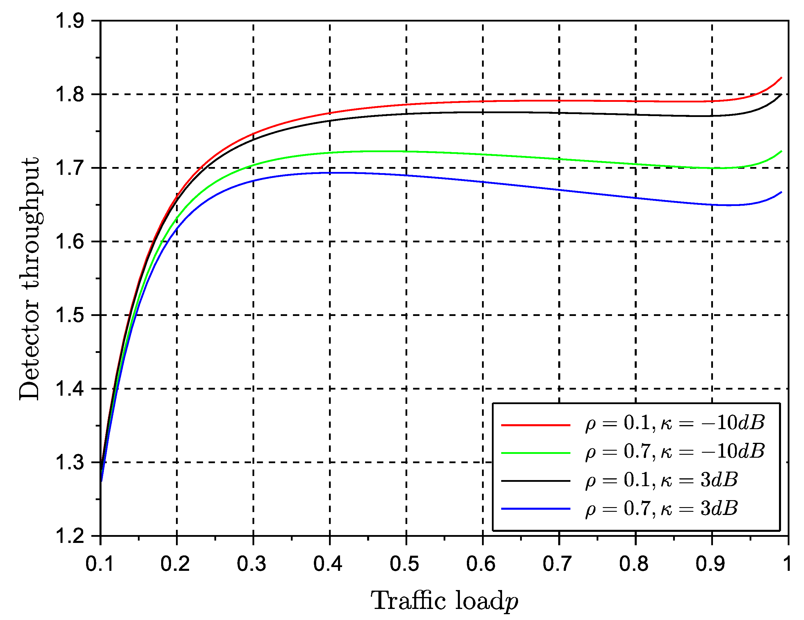
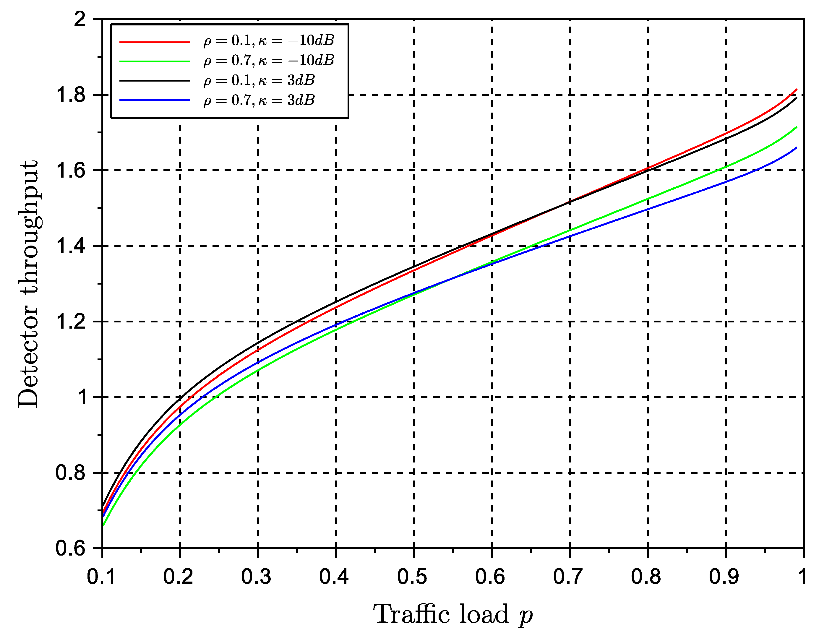
Figure 6 and
Figure 7 show the stable throughput
versus different traffic load values for both strategies.
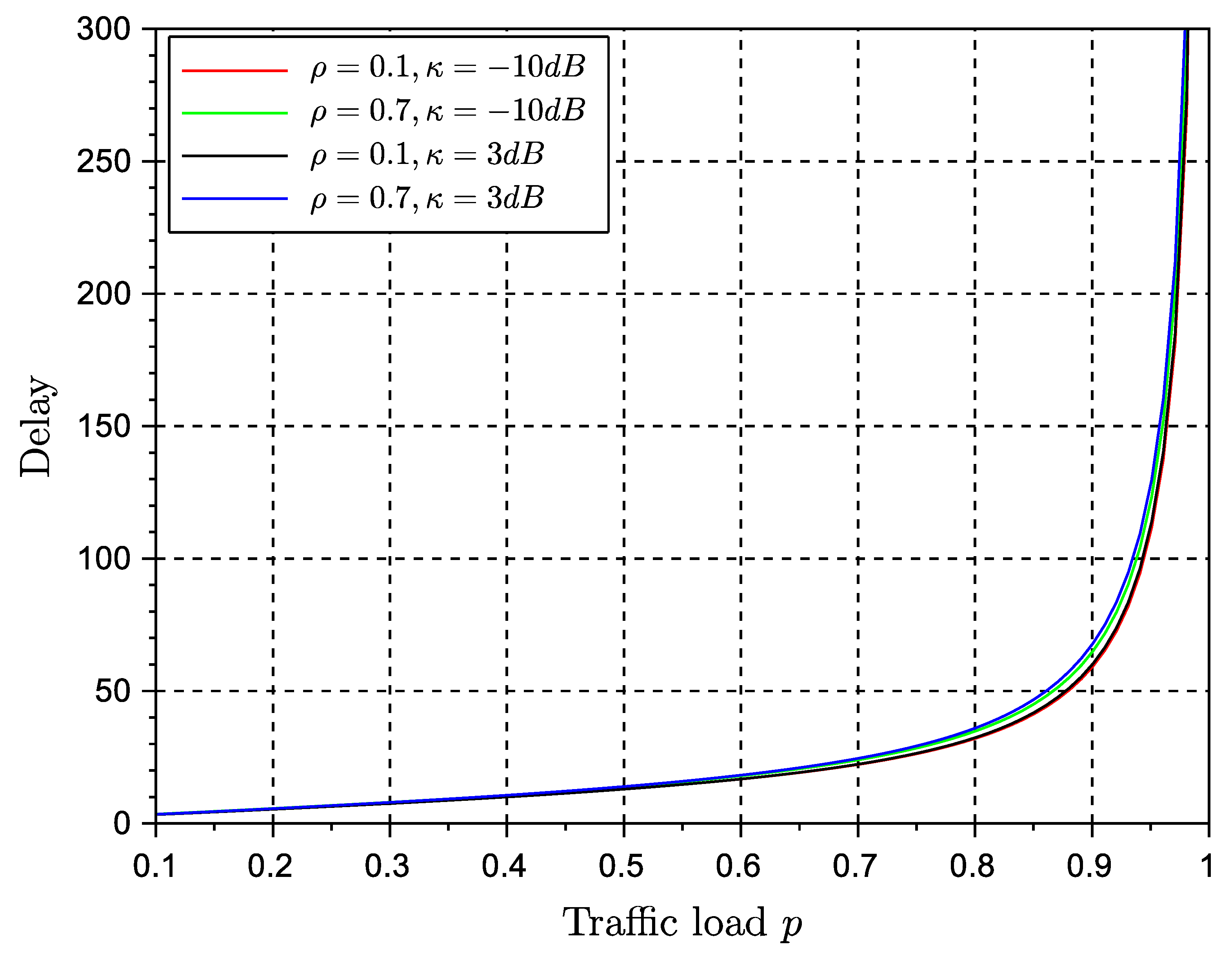
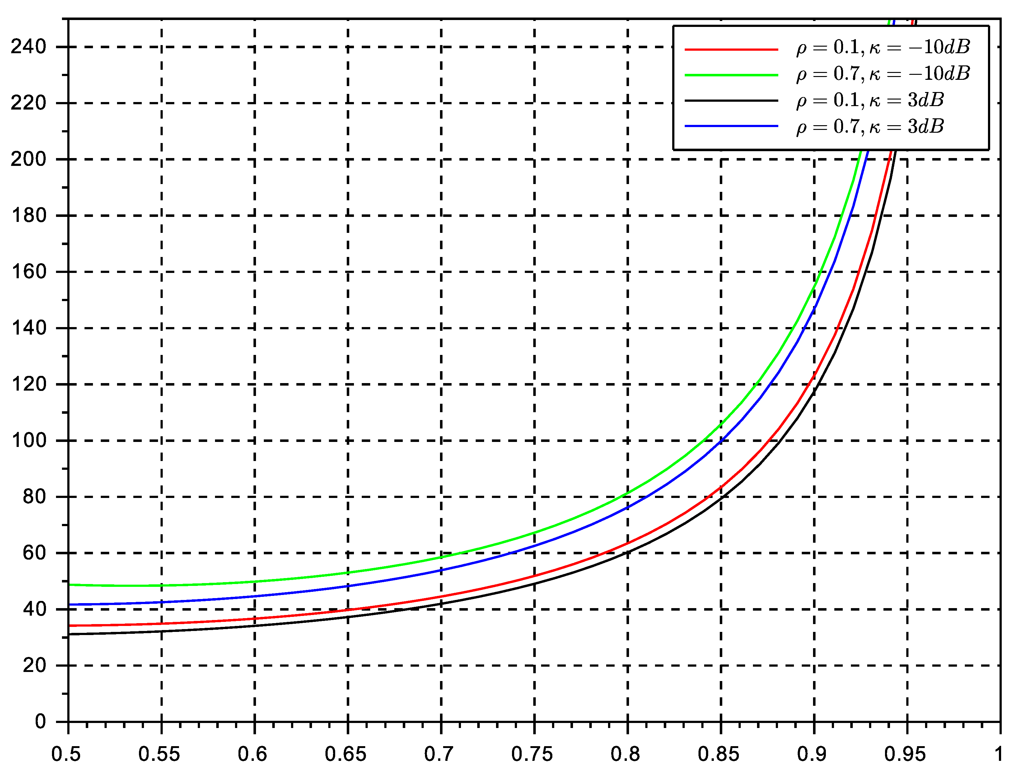
Figure 8 and
Figure 9 show the average delay experienced by the two retransmission strategy. It can be observed that the persistent retransmission scheme only slightly outperforms the random retransmission strategy. Both strategies seem to be able to achieve the maximum throughput estimates in previous workd and also in this paper in (
14):
. This is a significant result that paves the way for further analysis about the equivalence of stability and throughout metrics of the protocol. The use of a multiple antenna receiver has improved significantly the throughput and delay of the protocol in comparison with the results in our conference paper. They can be further improved by adding more antennas at the receiver side. The effects of channel correlation and line of sight are also visible as degrading issues. However, the gain provided by the diversity combining multiple antenna receiver is still significant enough to justify the rise of complexity of a multiple antenna receiver.
It is worth pointing out that the main virtues of the random retransmission strategy cannot be fully observed in the figures provided here. The random strategy will be optimum in networks affected by deep and long fades, or with terminals with long term degrading channel conditions. Therefore, the reader should keep in mind that random retransmission will play an important role in particular network situations. Future networks are meant to be more adaptive and cognitive to network and channel conditions, and therefore, it is expected that different backlog retransmission strategies can be adopted on the fly to maximize performance. Another aspect to point out is that in comparison with ALOHA solutions, NDMA protocols are capable to adopt persistent retransmission strategies, which in ALOHA is practically impossible. Once a collision event occurs in ALOHA, terminals must engage in random backlog retransmission algorithms, mainly because the repetition of the same collision event (used in persistent retransmission schemes) leads inevitably to unstable performance. This is another proof that NDMA is considerably better in terms of stability than its ALOHA counterparts.
Regarding delay, both algorithms seem to achieve the same performance. Delay is degraded as traffic load reaches the maximum channel transmission rate. The values of delay suggest that NDMA has good performance for real-time systems only at moderate traffic loads. The persistent strategy seemed to have the best performance. We remind the reader that the original protocol ignores the effects of backlog traffic, whereas in the present approach we estimate the effects of backlog traffic by inducing further retransmissions so that we can evaluate the performance of the algorithm in such conditions.
The results shown in here have been obtained using the assumption of independence of queues. This assumption is valid at medium traffic loads. Therefore, in particular delay, will lose accuracy at high traffic loads. It is also worth pointing out that the results of the random retransmission strategy were obtained under the assumption of the backlog retransmission process to match the transmission rate of the system. In practice, it is difficult to achieve this transmission control at low traffic loads. Therefore the validity of the results increases at medium and relatively high traffic loads.
