Abstract
The present study’s main objective was to determine the applicability of organic phase change materials (PCMs) in a building’s envelope construction system for the passive provision of comfortable indoor thermal conditions over one year based on thermal inertia in Mexico City. Research on PCMs relate mainly to their use in building envelope construction systems to reduce energy consumption for mechanical indoor thermal conditioning—not in passive systems. Computer simulation results of mean indoor temperature variations are presented with the objective of evaluating these construction systems’ thermal inertia properties. In the present study, dynamic thermal simulations (DTS), using EnergyPlus software, of ten 1 m3 test units with envelope construction systems combining organic PCMs of different fusion temperatures with conventional materials were performed. Based on the results, it is concluded that the implementation of organic PCMs with a fusion temperature around 25 °C in combination with aerated concrete in a space envelope results in the highest number of hours the indoor temperatures remain within the comfort range throughout a typical year, due to the decrement of indoor temperature oscillations and, to a large extent, to thermal lag.
1. Introduction
Today, there is a need to implement light-weighted building construction systems in response to the accelerated growth of urban areas; in general, light-weighted construction systems need less installation time with fewer material resources [1]. However, in most cases, light-weighted construction systems in buildings imply the use of Heating Ventilating and Air Conditioning (HVAC) systems for its thermal conditioning. Light-weighted materials are usually materials with thermal insulation properties; insulated spaces reduce heat exchange between indoor and outdoor environments through the space envelope, so heat must be artificially provided to, or removed from, the indoor space.
If HVAC systems for artificial thermal conditioning need to be excluded in temperate climates, and passive systems are implemented instead, then materials with thermal mass properties need to be used in the building’s construction systems. Thermal mass properties of building envelopes reduce indoor temperature oscillations and lag thermal conduction. Materials with thermal mass properties have a better application in climates with outdoor temperatures oscillations with magnitudes of 10 °C or more [2]. A material’s thermal mass property is closely related to high mass density; therefore, a construction system based on light-weighted materials has a lack of thermal mass.
Because of today’s energy crisis, there is a need to implement passive strategies for thermal conditioning (by natural means) as much as possible. Due to cities’ accelerated growth, there is also a need to construct buildings as fast as possible. It is viable, therefore, to apply passive strategies for thermal conditioning in temperate climates—such as Mexico City’s climate—as the energy available in the outdoor environment can be used to regulate indoor thermal conditions. Within Mexico City’s traditional and vernacular construction, building envelope construction systems have included materials with thermal mass properties. However, during the last several decades, Mexico City’s building construction systems have increasingly incorporated light-weighted materials with the implication of an increased use of mechanical systems for indoor thermal conditioning. In order to reduce energy consumption due to artificial thermal conditioning, there is a need to develop building envelope construction systems that can modulate the energy present in the indoor environment by first storing it and then slowly releasing it based on materials that are light-weighted, but have properties similar to those of thermal mass.
Recent research [3,4,5,6,7,8,9,10,11] on relatively light-weighted materials with thermal inertia properties relate to low fusion phase change materials (PCMs), which, under ambient temperatures, absorb heat to the point of complete fusion and later release it until they are completely solidified, yielding thermal inertia effects when implemented. Some thermal energy storage systems are designed to mainly work with latent heat as opposed to sensible heat in order to manage more quantities of energy; some examples are those implementing PCMs. Today’s interest to incorporate PCMs into building construction systems is to store latent heat within building envelopes for passive indoor conditioning. PCMs have great potential in light-weighted construction systems implemented in climates with great temperature variations [3]. The implementation of a PCM in building construction systems may allow light-weighted building structures to behave as massive, heavy structures with thermal inertia effects. This is feasibly achievable by taking advantage of a substance’s latent heat phase change. Thermal inertia is closely related to thermal mass, so PCMs perform in a manner similar to that of dense materials with thermal mass properties. However, research on PCMs relate mainly to their use in building envelope construction systems to reduce energy consumption for mechanical indoor thermal conditioning [3,4,5,6,7,12,13]—not in passive systems.
PCMs are starting to be viewed as an alternative for use in light-weighted building envelope systems [14], not only because PCMs have a relatively lower mass density than traditional and commonly used construction materials such as concrete, but also because of their thermal inertia effects. Hashou et al. developed a thermal inertia index to evaluate the ability of PCMs to resist heat transfer and store large amounts of heat either from outdoor or indoor environments, mentioning that material thermal inertia is the product of the thermal resistance and the heat storage coefficient [8]. Conventional materials are mainly used for storing sensible heat. However, PCMs are able to store latent heat, in addition to sensible heat, at ambient temperatures. Recent research [9] has shown that the amount of sensible heat storage in PCMs is not constant throughout the year, but is reduced during those seasons when the PCMs experience phase changes for relatively long periods of time. If no phase change occurs, the kind of heat that is stored is completely sensible, which depends on the volumetric heat capacity of the PCM.
Recent studies have evaluated PCMs in terms of time increment during which indoor temperatures stay within the comfort zone [10,12], but mainly in terms of building energy efficiency related to artificial thermal conditioning [12]. Related either to the occupant comfort zone only or building energy efficiency in terms of artificial conditioning, three parameters have been important in studies on the thermal evaluation of PCMs: thermal lag [10,12], the decrement of peak temperature oscillations [9,12,13,15,16,17,18], and the time during which indoor temperatures remain within the thermal comfort range [12], the latter of which is not frequently addressed.
Thermal lag has been addressed to evaluate PCM heat storage ability under periodic boundary conditions [8,14], but not to evaluate its ability to increase the number of hours the indoor temperatures stay within the comfort zone (comfort range). The decrement of peak temperature has been strongly correlated to PCM’s ability to store latent heat [8]; however, the correlation with time lag has been less accurate [11]. The fusion temperature of a PCM has been closely related (although not frequently) to the space occupant thermal comfort range and indoor temperature oscillation reductions [10,12], as well as to the quantity of the stored latent heat [9]. Although PCMs have been evaluated in terms of the occupant’s comfort zone, PCMs have not been specifically evaluated in terms of their applicability in passive systems for indoor thermal conditioning. However, Sharifi et al. has suggested that PCMs can be used as passive heat storage units in the walls by increasing the amount of PCM [12]. In the present work, we propose to evaluate PCMs’ applicability for passive heat storage based on the selection of the correct fusion temperature and the combination with conventional materials.
In terms of climatic data, the efficiency of a PCM has been declared as dependent on the input temperature profile [12]. Many studies on PCMs have been based on thermal simulations using either bi-dimensional [12] or mono-dimensional [13] heat transfer models with sinusoidal temperature data [18] or periodical data [15]. Evola et al. performed a study based on a periodical regime to evaluate PCM’s thermal efficiency, comparing its performance within a temperate climate with a hot climate [10], concluding that the best performance was obtained within the temperate climate. However, they concluded that a PCM should be evaluated over a long time span (several weeks or even months) for a deeper understanding of its fusion process, due to the fact that there are some times of the year when the fusion phase may not be completed or even developed at all.
PCMs have also been evaluated in terms of their ability to slow heat gains or losses from or towards indoor environments [9,15], and it has been concluded that the duration of the phase transition is proportional to how long the inner surface temperature remains constant at or near the melting point. However, these studies have not lasted over a year. However, some studies related to organic PCMs [13,14] have been performed for certain seasons of the year, and it was concluded that their applicability depends on the time of the year.
The present study’s main objective was to determine the applicability of organic PCMs in a building’s envelope construction system and in combination with conventional materials for the passive provision of comfortable indoor thermal conditions for one year based on thermal inertia in Mexico City. The first part of the paper describes the studied materials and the study methodology; subsequently, results are presented and discussed; finally, conclusions are addressed.
2. Materials and Methods
2.1. Description of the Study
Ten case scenarios based on 1 m3 prototypes with construction systems composed of different materials were firstly 3D-modeled to subsequently simulate their thermal performance using EnergyPlus version 8.5.0 based on a dynamic thermal simulation (DTS).These case scenarios were divided into two groups: (a) some of the studied construction systems included PCMs in combination with conventional construction materials, and (b) others included only conventional construction materials. Walls, ceilings, and floors were modeled with a 0.10 m thickness. None of the simulated prototypes included windows so that only the thermal contribution of the space envelope construction systems with and without PCMs towards the indoor environment was studied, and parameters pertaining to heat gain or loss due to windows could be discarded. PCMs were modeled as macro-encapsulated within a thin steel layer and as intermediate layers within the construction systems, and were applied to the west, east, and south walls and to the ceilings, as these envelope surfaces are more exposed to solar radiation than the floor and the north wall are; therefore, the north wall and the floor were insulated so that, as much as possible, heat gain and loss parameters pertaining to these surfaces could be discarded. Annual hourly mean indoor temperatures for a typical year in Mexico City were obtained as a result of the DTS. In order to evaluate the construction systems’ thermal inertia effects, indoor temperature oscillations and time lags, with respect to outdoor temperature oscillations, were measured.
2.2. PCMs and Latent Energy Storage
PCM energy storage processes are based on fusion latent heat—an endothermic process that leads to energy storage in the PCM—and solidification latent heat—an exothermic process that leads to the release of the stored energy in the PCM [7].
The energy storage and release process consists of three stages:
- (1)
- First, the PCM receives heat form an external heat source, such as the sun (helio-thermal energy), and elevates its temperature by absorbing and storing sensible heat until the PCM’s fusion temperature is reached (, where is the stored sensible heat in its solid phase, is the PCM’s mass, is the PCM’s specific heat capacity at constant pressure during its solid phase, and is the temperature change from the initial temperature up to the PCM’s fusion temperature ).
- (2)
- After the PCM reaches its fusion temperature, it leaves the solid phase, enters into an incompressible fluid phase, continues to store energy without increasing its temperature, and fuses until the absorbed energy equals its fusion latent heat (, where refers to the stored latent heat by the PCM during its transition from the solid phase to the incompressible fluid phase, and is the PCM’s latent fusion heat).
- (3)
- Finally, after the PCM reaches an incompressible fluid phase, its temperature again is elevated as it continues to store sensible heat (, where is the stored sensible heat during the PCM’s incompressible fluid phase, is the PCM’s specific heat capacity at constant pressure during its fluid incompressible phase, and is the temperature change from the PCM’s fusion temperature to a temperature ).
These three stages are illustrated in Figure 1.
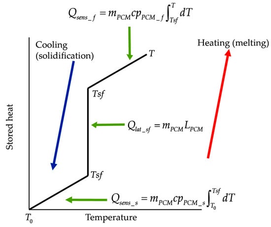
Figure 1.
Heat storage stages of a phase change material (PCM).
When a PCM liquefies, it absorbs and stores large amounts of heat (latent heat); when it solidifies, the previously absorbed and stored heat is released. Based on their thermal inertia effects, a PCM compared to a conventional construction material also absorbs and stores solar heat, conducting small amounts of this heat towards the indoor space—as PCM’s thermal conductivity is low—maintaining indoor temperatures relatively low, and later releases the stored heat towards the indoor environment when the outdoor temperature decreases. As a result, two effects take place: (1) the times at which maximum and the minimum indoor temperatures occur, compared with the times at which the maximum and minimum outdoor temperatures occur, are temporarily lagged (this effect is known as thermal lag); (2) the maximum and minimum indoor temperature peaks, compared with the maximum and minimum outdoor temperature peaks, are dampened (this effect is known as thermal damping). Both effects are characteristic of thermal mass materials with thermal inertia effects.
2.3. Thermal Inertia Applicability as a Passive Indoor Acclimatization Strategy
In order to determine PCMs’ thermal inertia effects within Mexico City’s climate in indoor passive thermal conditioning strategies, the number of days presenting ambient temperatures higher or equal to 10 °C oscillations were quantified based on daily and hourly climatic data [19]; the number of days are presented in Table 1.

Table 1.
Number of days with ambient temperatures higher or equal to 10 °C oscillations within a typical Mexico City climatic year as well as the mean annual temperature oscillation, where Tamb corresponds to the outdoor ambient temperature.
From Table 1, it is observed that ambient temperatures higher or equal to 10 °C oscillations are present during 83.3% of a typical year in Mexico City. Therefore, it is deduced that the implementation of passive strategies based on thermal inertia for indoor building thermal conditioning in Mexico City is feasible [20].
2.4. Determination of Comfort Intervals
The construction system performs thermally, based on thermal inertia, when thermal damping and thermal lag effects are present. These two effects allow indoor temperatures to remain within the range of thermally comfortable conditions (thermal comfort range) for a long time without the use of auxiliary mechanical systems for artificial thermal conditioning.
Because one objective of the present work is to study construction systems for passive indoor thermal conditioning, an adaptive model was used for the calculation of the thermal comfort range. The implemented model is correlated to Mexico City’s mean monthly temperatures. The thermal comfort range is defined based on the thermally neutral temperature calculated based on Equation (1) of Dear’s model [21]. This model has been implemented in other studies on passive building acclimatization for Mexico City [22].
where is Mexico City’s mean monthly ambient (outdoor) temperature and is the thermally neutral temperature. From Equation (2), the thermal comfort range was calculated by adding and subtracting 2.5 °C from the thermally neutral temperature in order to obtain the maximum thermally admissible temperature (thermal comfort range upper limit) and the minimum thermally admissible temperature (thermal comfort range lower limit).
Monthly upper and lower limits of the thermal comfort range (minimum and maximum temperatures of the comfort range) for Mexico City are given in Table 2.
Table 2.
Monthly thermal comfort range upper and lower limits in °C for Mexico City.
2.5. PCM Selection
According to Fleischer [7], in order to obtain indoor temperatures with fewer oscillations with respect to the outdoor temperatures by implementing a PCM in a construction system its fusion temperature must be close to the maximum thermally admissible temperature (corresponding to the thermal comfort range upper limit temperature), so indoor temperatures are able to remain within the thermal comfort range as long as possible. The cyclical exterior temperature variations reflect indoor cyclical temperature variations as well, but are out-phased and dampened due to the thermal inertia effect of the building construction envelope materials.
The use of a PCM with a fusion temperature close to the maximum thermally admissible temperature allows for a longer fusion time period, so latent heat is absorbed during an extended time resulting in a greater thermal lag. At sunset, when outdoor temperatures descend, the PCM will solidify for a much longer time period, and latent heat release towards the indoor space will occur with a greater time lag, producing a thermal lag effect. Therefore, thermal inertia is determined by the PCM fusion temperature.
Another parameter to consider when selecting a PCM is the amount of latent heat it needs for its fusion per mass unit, i.e., the amount of energy the PCM is able to store. The amount of energy it needs for its fusion per mass unit is proportional to the amount of energy that can be stored with less mass. Additionally, the PCM must have a high specific heat capacity at constant pressure so that higher amounts of sensible heat within less of its mass can be stored before and after its fusion process.
On the other hand, it is desirable for the PCM to have a high thermal conductivity so that heat is, as much as possible, efficiently conducted through the constructive system towards or away from the indoor space. However, it has been found that PCMs have, in general, low thermal conductivities. Therefore, the material and thickness of the PCM container must be strategically selected to enhance the thermal conductance of the construction system. Additionally, the order of the material layers that compose the construction system affect the amount of thermal damping and thermal lag effects.
There are two basic types of PCMs: (1) organic, which are those derived from oil (petroleum) and from biological beings’ fatty acids, and (2) inorganic, which are majorly hydrated inorganic salts with fusion and solidification processes based on water absorption and release [3,7]. Organic PCMs exhibit a long-term physical and chemical stability and have high fusion latent heat; however, these are inflammable (their ignition temperature is around 200 °C) and can dissolve their container if it is made out of a polymer with a low thermal conductivity. Inorganic PCMs also have high fusion latent heat, but a higher thermal conductivity; their ignition temperature is also high (around 900 °C). Inorganic PCMs are not as physically and chemically stable as organic PCMs and present phase segregation, meaning that the material phase transition does not completely terminate. In addition, inorganic PCMs may corrode their container in case it is made out of metal [7].
Based on the previously mentioned conditions and characteristics, paraffin-based organic Rubitherm PCMs from the RT series and HC type [23] were selected for the present study (RT is the brand name of the Rubitherm's organic PCM series and HC is the sub-brand name of the Rubitherm’s organic PCM line with major heat capacity [23]). The HC-type PCMs can store a greater amount of latent heat per mass unit. More specifically, the selected PCMs were RT18HC, RT22HC, and RT25HC, corresponding, respectively, to fusion temperatures around the comfort range lower limit temperature (19.9 °C), the mean temperature of the lower and upper limit temperatures of the comfort range (23.0 °C), and the comfort range upper limit temperature (26.2 °C). The thermophysical properties of the selected PCMs are presented in Table 3.
Table 3.
Thermophysical properties of the RT18HC, RT22HC, and RT25HC PCMs [24,25,26].
2.6. Design of Test Units
In order to study the temperature evolution of an indoor space using PCMs in the envelope construction system, ten 1 m3 test units were designed. All test units were 3D-modeled, using DesignBuilder version 3.4.0.041, with envelopes of construction systems that included common light-weighted materials commonly used in Mexico: gypsum board and aerated concrete. The total thickness of each wall, ceiling, and floor equaled 0.1 m. The base test unit plan and isometric are presented in Figure 2.
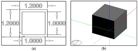
Figure 2.
(a) A base test unit plan, and (b) a base test unit isometric modeled using DesignBuilder software; the triangle represents the north orientation.
Neither windows nor openings were included in the test units in order to avoid heat gains or losses different from the ones provided by the opaque envelope (walls, floor, and ceiling), as one of the main objectives of this study was to analyze the indoor temperature evolution and variation dependent on the opaque envelope’s heat contribution using PCMs.
The construction systems of the envelopes of all test units were designed based on a sandwich-type configuration composed of three material layers; all test unit envelopes included a floor, four walls, and a ceiling. Six test units were modeled with envelopes with construction systems that included PCMs as the intermediate layer; the other two layers corresponded to the conventional light-weighted materials commonly used in Mexico. The implemented PCMs were proposed to be encapsulated by a carbon steel container with 0.0009-m-thick walls. The PCM layer, including its carbon steel container, was proposed to have a 0.074 m thickness. The construction systems that included PCMs were applied to the west, east, and south walls, as well as the ceiling, considering that these are the envelope surfaces with most solar incidence due to Mexico City’s latitude. The north wall and floor had an insulated construction system to avoid, as much as possible, heat and gain losses through these envelope surfaces. For all tensest units, terracotta red paint with a 0.7 solar absorptance (αs) was applied to the outermost layer. Each test unit, with its own and unique envelop construction system configuration, represents a study case scenario. The thermophysical properties of all the construction materials used in the construction systems are presented in Table 4.
Table 4.
Test units’ construction material’s thermophysical properties.
2.7. Case Studies’ Configuration
All 10 case scenarios were classified into two groups: (1) the first group, denominated as the GYP group, included five test units with an envelope construction system composed of an interior and exterior gypsum layer, and an intermediate PCM layer; and (2) the second group, denominated as the AC group, included five test units with an interior and exterior aerated concrete layer, and an intermediate PCM layer.
For each group, three test units included a specific fusion temperature PCM as the intermediate construction system layer applied to the west, east, and south walls, and the ceiling; a fourth test unit included polyurethane insulation as the intermediate construction system layer applied to the west, east, and south walls, and the ceiling; a fifth test unit included gypsum applied to the intermediate construction system layer (for the GYP group) and aerated concrete as the intermediate construction system layer (for the AC group) applied to the west, east, and south walls, and the ceiling. Therefore, the fifth test unit of each group includes a construction system applied to the walls and ceiling composed of three layers of the same material (gypsum or aerated concrete), which can also be considered as one homogeneous layer. For all test units of both groups, the north wall and floor included polyurethane insulation as the intermediate layer. All 10 case scenarios’ construction system layer configuration of walls and ceiling are presented in Table 5.
Table 5.
Study case scenarios with their construction system layer configuration.“PCMXX” indicates the using of the studied PCM’s as intermediate layer in the studied constructive systems, “INS” indicates the using of polyurethane insulation as intermediate layer in the studied constructive systems, “Only” indicates using of a construction system applied to the walls and ceiling composed of three layers of the same material, which can also be considered as one homogeneous layer.
All 10 case scenarios construction system layer configuration of walls and ceiling are illustrated in Figure 3.
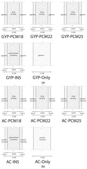
Figure 3.
(a) Walls and ceiling construction system corresponding to the GYP group of each case scenario. (b) Walls and ceiling construction system corresponding to the AC group of each case scenario.
All 10 case scenarios representing the envelope construction systems are illustrated in Figure 4.
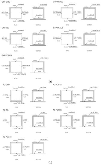
Figure 4.
(a) Envelope construction systems corresponding to the GYP group. (b) Envelope construction systems corresponding to the AC group.
Conductance (U) and thermal resistance (R) values of all case scenarios were calculated and are presented in Table 6.
Table 6.
Conductance values (U) and thermal resistance values (R) of all case scenarios.
2.8. DTS Analysis
Dynamic thermal simulation (DTS) using EnergyPlus version 8.5.0 was performed on all case scenarios. For those case scenarios with construction systems that included PCMs, the implemented solution algorithm was based on the finite differences heat conduction equation (CondFD) [27,28,29], with a 0.333 discretization factor [27], and a 60 time-step calculation. However, the CondFD algorithm does not properly read very thin material layers with a high thermal conductivity [30], such as the carbon steel PCM container walls; therefore, the carbon steel layers were omitted from the simulations and the PCM layers were considered with a 0.074 m thickness. This omission does not produce a significant error because the opposing surfaces of thin layers, with very high thermal conductivities, reach the same temperature within a very short time period; therefore, thermal resistance is extremely low.
In addition, EnergyPlus cannot directly read the latent energy storage properties of a PCM. Therefore, the latent heat energy storage property of a PCM needs to be described based on its temperature–enthalpy function. Accordingly to Miranda-Fuentes et al. [31], a PCM’s enthalpy, at a given temperature, is a function of the stored sensible and latent heat (proportional to the liquefied PCM mass), correlated as described in Equation (3):
where is the PCM’s enthalpy at a temperature, is the PCM’s specific heat at constant pressure, is the initial temperature needed as a reference to evaluate , is the PCM’s phase transition latent heat, and is the fused PCM mass fraction at a temperature which is calculated based on Equation (4):
Figure 5a–c present the temperature–enthalpy functions corresponding to the studied PCMs.
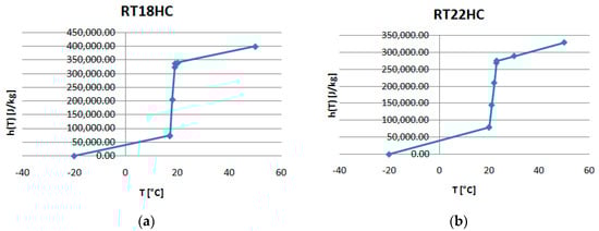
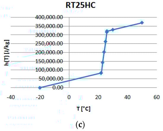
Figure 5.
Temperature-enthalpy functions of the studied PCMs: (a) RT18HC, (b) RT22HCand (c) RT25HC.
In the case of the insulated envelope test units (GYP-INS and AC-INS), and the homogeneous layer envelope test units (GYP-Only and AC-Only), the implemented solution algorithm is based on the conduction transfer function, and the simulation was done with a 60 time-step calculation.
In order to study the thermal effects of the selected PCMs on the indoor temperatures, the results from the simulations ran on those test units that included PCMs in their envelope, and were compared with the simulation results of those test units with an insulated envelope and a homogeneous layer envelope.
The simulation conditions, for all case scenarios, were as follows:
- No test units were simulated with internal heat gains due to human or animal occupation.
- No test units were simulated with internal heat gains due to electrical illumination systems or electrical equipment.
- No test units were simulated with natural ventilation nor heat gain and losses due to air infiltration.
- No test units were simulated with mechanical systems for artificial thermally comfortable air provision (fans, refrigeration, nor heating mechanical systems).
Before considering the simulation calculation, the following should also be noted [27,28,29]:
- Heat transfer through the constructive elements of all test units was considered as mono-dimensional.
- Isotropy in relation to the material properties was considered.
- The solidification and the fusion temperature ranges of all studied PCMs were always the same.
- The specific heat capacity of all materials was considered as constant.
- The latent heat of fusion of all studied PCMs was constant.
- The effects of subcooling, hysteresis and phase segregation were neglected due to the software’s non-capability to read the effects of these phenomena [29].
- Convection calculations at outside surfaces follow the logic of the DOE-2 algorithm (which uses correlations obtained by in-field experimental datum for rough and smooth surfaces [28]) and at inside surfaces follows the logic of the TARP algorithm (“Thermal Analysis Research Program”, which correlates, with the base on experimental laboratory datum, the convective heat transfer coefficient to the surface orientation and the difference between the surface and zone air temperatures), both of them explained in detail in [29].
The mathematical model of heat conduction solved by EnergyPlus is related to Fourier’s Law, as stated in Equation (5).
where is the mass density of the material, is the specific heat capacity of the material, is the thermal conductivity of the material, and denotes the time-dependent component of the heat flux through the material, and denotes the thermal gradient along the coordinate x of the material.
By using the CondFD algorithm, Equation (5) for PCM-constructive systems can be solved by dividing up the walls and ceiling in a certain number of slices in accordance with the discretization factor of 0.333. CondFD model is stated in Equation (6):
where the subindex i is related to the space coordinate of each slice of the wall or ceiling, whereas the index n relates to the time coordinate. A fully implicit scheme is used for the CondFD solver algorithm [27,28,29].
Incident heat flux at the outside surfaces of the constructive system are transferred by conduction through the walls and ceiling to the inside space. The heat balance in the outside surfaces of the constructive system is given in Equation (7):
where is the absorbed global solar radiation heat flux for the area unit, is the net thermal radiation flux exchange (infrared) with the air and surroundings for the area unit, is the convective flux exchange with the outside air for the area unit, and is the heat conduction though the wall or ceiling for the area unit. Simplified procedures generally combine the first three terms by using the concept of a sol–air temperature [29], which is considered implicitly by the software.
After performing all mono-dimensional heat transfer simulations for all case scenarios, the time during which indoor air temperatures remained within the thermal comfort range, presented in Table 2, was quantified. The purpose of this quantification was to relate that case scenario, corresponding to the higher number of hours within the thermal comfort range during the year, to the one with the best thermal performance in Mexico City.
3. Results
The time during which indoor air temperatures remained below (cool hours) and above (heat hours) the thermal comfort range was quantified. Thus, the number of hours the indoor air temperature remained within the thermal comfort range (comfort hours) was quantified based on Equation (8):
where, for all 8760 h within a year, is the number of hours within the thermal comfort range; is the number of hours below the thermal comfort range, and the number of hours over the thermal comfort range. These numbers are presented in Table 7 for all case studies. The case scenario with the highest number of thermally comfortable hours was the AC-PCM25 case.
Table 7.
The number of hours within a typical year when indoor temperatures corresponding to all case scenarios remained within the thermal comfort range (), below the thermal comfort range (), and over the thermal comfort range ().
In order to quantify the case scenarios construction systems thermal inertia based on their thermal damping and thermal lag effects, the results corresponding to the following days were analyzed:
- the day when the highest peak temperature of the year was registered (8 May);
- the day when the lowest peak temperature of the year was registered (25 December);
- the day when the temperature oscillations represent a typical year’s temperature oscillation (15 April).
Thermal damping was quantified as the magnitude of temperature oscillations, calculated as the difference between the highest peak temperature and the lowest peak temperature, based on Equation (9):
where is the temperature difference between the maximum temperature and the minimum temperature of a specific day (it applies for both outdoor and indoor temperatures).
Thermal lag was calculated as the time difference between the time the maximum outdoor temperature occurs, and the time the maximum indoor temperature occurs during a specific day, based on Equation (10):
where is the time difference, is the time the maximum indoor temperature occurs, and is the time the maximum outdoor temperature occurs during a specific day.
Figure 6a–c illustrate all case scenarios indoor temperature oscillations scenarios as well as the outdoor temperature corresponding to each analyzed day; Figure 7a–c illustrate indoor temperature variations of those case scenarios wherein indoor temperatures remained within the thermal comfort range for a greater number of hours.
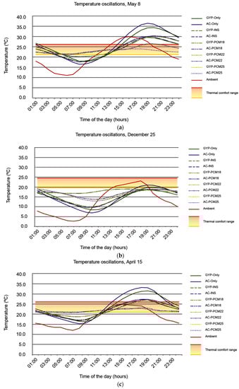
Figure 6.
All case scenarios indoor temperature oscillations temperature corresponding to (a) 8 May, (b) 25 December, and (c) 15 April.
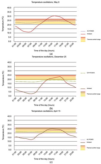
Figure 7.
Indoor temperature oscillations corresponding to those case scenarios presenting best thermal performance during (a) 8 May, (b) 25 December, and (c) 15 April.
4. Discussion
Table 7 presents the number of hours during which indoor temperatures are thermally comfortable, the number of hours during which indoor temperatures are over the comfort range upper limit, and the number of hours during which indoor temperatures are under the comfort range lower limit during a typical year in Mexico City. Based on these numbers, it is observed that when a PCM is implemented in a space envelope, the number of thermally comfortable hours are higher in comparison to those cases where the space envelope is completely insulated (GYP-INS, AC-INS) or where a homogeneous layer is implemented (GYP-Only, AC-Only). Therefore, in those cases where PCMs are implemented as the intermediate envelope layer, the number of hours during which indoor temperatures are above () and below () the thermal comfort range is reduced due to the fact that the PCM superior and inferior fusion temperature limits are increased. For those cases when a PCM with a minimum fusion temperature of 22 °C and a maximum fusion temperature of 26 °C (GYP-PCM25 and AC-PCM25), temperatures above the thermal comfort range () are zero. For all cases, temperatures below the thermal comfort range () are always present. However, when the PCM fusion temperature is increased, the percentage of the hours present throughout the year are reduced, from 57.53% in the GYP-PCM18 case, down to 26.74% in the AC-PCM25 case (see Table 7).
The case scenario presenting the highest number is the AC-PCM25; in other words, when a PCM with a minimum fusion temperature of 22 °C and a maximum fusion temperature of 26 °C (RT25HC) is implemented as the intermediate layer between two aerated concrete layers, in the west, south, and east walls, and the ceiling, the indoor thermally comfortable hours are increased.
While a PCM is a substance that allows energy storage for its later release, it is the strategic configuration of the construction system layers that allows the best use of the stored energy. Considering the gypsum and aerated concrete volumetric heat capacities, 798,000 J/m3·K and 735,000 J/m3·K, respectively, it appears that the use of gypsum as the exterior and interior envelope layers would allow for a higher number of thermally comfortable indoor temperatures due to the fact that gypsum has a greater volumetric heat capacity than aerated concrete does. However, aerated concrete as exterior and interior layers allows for a higher number of indoor temperatures within the comfort range (except for the AC-PCM18 and AC-Only cases) in comparison to those cases where gypsum is used as exterior and interior layers, due to the fact that aerated concrete’s thermal conductivity is higher than gypsum (Table 4); therefore, heat is more efficiently conducted through the envelope. Thus, not only volumetric heat capacity is determinant in a constructive system’s performance when passive thermal conditioning needs to be applied, but also an adequate thermal conductivity of the exterior and interior layers surrounding the PCM. As future work, layer thicknesses of interior and exterior layers, as well as the PCM layer, in relation to the thermal performance of construction systems, should be studied more in depth.
When comparing the GYP-PCM18 case with the AC-PCM18 case, it was observed that the use of aerate concrete, compared with gypsum, as the interior and exterior layers surrounding the 18 °C fusion PCM decreases the number of indoor thermal comfort hours () more. This is due to the fact that, from all studied PCMs, the RT18HC has the lowest fusion temperatures and the time needed for its solidification and fusion is less. When the RT18HC PCM is implemented as the intermediate layer surrounded by aerated concrete layers, which have a higher thermal conductivity than gypsum layers do, the relatively small amount of stored heat will rapidly flow from the outdoor environment towards the indoor environment and vice versa.
When the indoor temperature evolution is compared with the outdoor temperature evolution on 8 May (Figure 7a), indoor temperatures remain within the thermal comfort range during the entire day in the AC-PCM25 case. When this comparison is made for 25 December (Figure 7b), it is the AC-PCM18 case that presents the highest number of indoor temperatures within the thermal comfort range; the rest of the study cases for this day resulted in indoor temperatures below the comfort range (Figure 6b). For 15 April, AC-PCM25 tends to maintain indoor temperatures within the comfort range for most of the day (Figure 7c).
Therefore, in those case scenarios where PCMs are implemented, a higher number of thermally comfortable hours is due to the fact that indoor temperature oscillations are smaller compared to those case scenarios with an insulated envelope (GYP-INS and AC-INS cases) or a homogeneous material envelope (GYP-Only and AC-Only cases). This can be validated by data in Table 8 and Figure 6a–c.
Table 8.
Indoor and ambient (outdoor) temperature oscillations for all case scenarios on 8 May, 25 December, and 15 April.
For all case scenarios, time differences () between maximum indoor and outdoor temperatures occurrence are smaller than 5 h, as presented in Table 9. On 25 December, values are negative for the GYP-PCM18 and the AC-PCM18 cases because the PCM starts melting and absorbing latent heat from the indoor space 2 h before the outdoor temperature reaches its maximum. In those cases, equals zero, and the PCM starts melting and absorbing latent heat from the indoor space at the moment the outdoor temperature reaches its maximum.
Table 9.
Time differences between the time the maximum indoor temperature occurs and the time the maximum outdoor temperature occurs for each case scenario on 8 May, 25 December, and 15 April.
From Table 8 and Table 9, it is observed that, as the PCM fusion temperature nears the maximum admissible thermally comfortable temperature, the indoor temperature oscillations decrease with respect to the outdoor temperatures, so indoor temperatures stay within the thermal comfort range for a higher number of hours because more latent heat is absorbed (for its fusion) and released (for its solidification) by the PCM during its phase change. As the release and absorption of latent heat, in addition to sensible heat, increases, temperature oscillations decline because indoor heat gain and losses decrease in speed. Therefore, as the difference between the PCM fusion temperature and the maximum thermally admissible temperature decreases, the amount of latent heat that is absorbed or released decreases. In some cases, latent heat is only absorbed; in others, it is only released. The ideal case is achieved when smaller indoor temperature oscillations are obtained, and that happens when latent heat is both absorbed and released. Additionally, as the PCM fusion temperature nears the maximum admissible thermally comfortable temperature, the thermal lag effect decreases, because the PCM starts melting around the time the outdoor temperature reaches its maximum.
5. Conclusions
The present study’s main objective was to determine PCMs’ applicability in building’s envelope construction systems for the passive provision of comfortable indoor thermal conditions based on thermal inertia in Mexico City with 10 °C temperature oscillations.
When PCMs are implemented for passive thermal indoor conditioning, i.e., when latent heat is managed in addition to sensible heat, thermal lag is not predominant, but thermal damping is. As more latent heat is managed, thermal damping increases and thermal lag decreases. This does not mean PCM’s volumetric heat capacity is smaller. On the contrary, the studied PCMs have, on average, 123.1% more volumetric heat capacity than solid aerated concrete, and 100% more volumetric heat capacity than liquid aerated concrete, 105.5% more volumetric heat capacity than solid gypsum, and 84.2% more volumetric heat capacity than liquid gypsum. PCMs have large volumetric heat capacities when compared with conventional materials, meaning that they are able to store large amounts of sensible heat. However, PCMs also have a great latent heat storage capacity. As more latent heat is managed when implementing a PCM, the time taken for it to be absorbed and/or released increases, yielding greater indoor thermal damping. Additionally, the thermal lag effect decreases, because the PCM starts melting and absorbing latent heat from the indoor space over a length of time that is similar to the time outdoor temperatures take to reach their peak—sometimes even faster(negative thermal lags)—and solidifies latent heat and releases it to the indoor space over a length of time that is similar to the time taken for outdoor temperatures to reach their peak. Therefore, when managing latent heat, thermal dampening increases the time during which indoor temperatures remain within the thermal comfort range more so than thermal lag; this is due to a combination of the PCM’s high latent heat storage capacity and its high volumetric heat capacity for sensible heat storage. When managing only sensible heat, thermal dampening and thermal lag increase the time during which the indoor temperatures remain within the thermal comfort range; this is due to a combination of the material's volumetric heat capacity and the medium's conductivity. As volumetric heat capacity increases, thermal lag increases.
On the other hand, the desired level of thermal conductance of the construction system when latent heat is managed varies. In order to increase indoor thermally comfortable hours and increase PCM latent heat storage capacity, the thermal conductance of the layer surrounding the PCM must increase because a greater amount of heat is being managed and thus needs to be conducted. As PCM latent heat storage capacity decreases, the thermal conductance of the layer surrounding the PCM needs to decrease because a lower amount of latent heat is being managed and, if easily conducted, can be rapidly released and lost. When sensible heat is managed, in order to increase indoor thermally comfortable hours, the volumetric heat capacity of the construction system materials decreases, thermal conductivity must also decrease; as the volumetric heat capacity of the construction system materials increases, thermal conductivity must increase.
Depending on how close or how far the PCM fusion temperature is to the maximum thermally acceptable temperature, it behaves more like a PCM with an enhanced thermal performance (with a fusion point close to the maximum thermally acceptable temperature) or like a conventional material with no phase changes at ambient temperatures but with a high volumetric heat capacity (with a fusion point far from the maximum thermally acceptable temperature). Therefore, depending on its fusion point, the latent heat storage capacity, and the time of the year, a PCM in Mexico City can behave like a thermal mass material, only releasing and absorbing sensible heat, or like a high-performance material with high thermal inertia, very slowly releasing and absorbing latent heat for its phase change over a long period.
During the day of a year with the lowest peak ambient temperatures in Mexico City (25 December), the PCM with a fusion temperature around 18 °C has the greatest thermal dampening effect and increases the time during which indoor temperatures remain within the thermal comfort range because it absorbs (fusion latent heat) and releases (solidification latent heat) latent heat; therefore, it behaves completely like a high-performance PCM. The PCM with a fusion temperature around 22 °C mainly absorbs fusion latent heat during its melting process and absorbs and releases sensible heat; therefore, it behaves partially like a high-performance PCM and like a thermal mass conventional material. The PCM with a fusion temperature around 25 °C mainly absorbs and releases sensible heat; therefore, it mostly behaves like a thermal mass conventional material.
During the day of the year with the highest peak ambient temperatures in Mexico City (8 May) and the day with typical oscillation outdoor temperatures (15 April), the PCM with a fusion temperature around 25 °C has the greatest thermal dampening effect and increases the time during which indoor temperatures remain within the thermal comfort range because it absorbs (fusion latent heat) and releases (solidification latent heat) latent heat; therefore, it behaves completely like a high-performance PCM. The PCM with a fusion temperature around 22 °C mainly releases fusion latent heat during its solidification and absorbs and releases sensible heat; therefore, it behaves partially like a high-performance PCM and like a thermal mass conventional material. The PCM with a fusion temperature around 18 °C mainly absorbs and releases sensible heat; therefore, it mostly behaves like a thermal mass conventional material.
The present work results lead to the conclusion that PCMs in space envelopes have great potential for passive indoor thermal conditioning. As the difference between the PCM fusion temperature and the maximum thermally admissible temperature decreases, the performance of the PCM increases and the number of thermally comfortable indoor temperatures increases (sometimes even up to 24 h). Even when the PCM does not perform well, it still performs as a high thermal mass material because of its high volumetric heat capacity, although the number of thermally comfortable indoor temperatures are not as high. It is necessary to select a PCM with a fusion temperature that produces the highest number of thermally comfortable indoor temperatures throughout the year. For Mexico City and the studied case scenarios applying different fusion temperatures, a PCM with a fusion temperature around 25 °C, in combination with a medium thermal conductivity material (aerated concrete), produced the highest number of thermally comfortable indoor temperatures over the year. During the coldest days, the PCM with a fusion temperature around 18 °C, in combination with a low thermal conductivity material (gypsum), produced the highest number of thermally comfortable indoor temperatures.
In the future, the amount of thermal conductivity of conventional materials that should be combined with PCMs, as well as what thickness best enhances PCMs’ thermal performance, needs to be determined. Additionally, a higher variety of materials with different volumetric heat capacities and thermal conductivities to be combined with the PCM need to be studied. Last but not least, the present work case scenarios need to be replicated experimentally to confirm these results.
Acknowledgments
This work has been supported by the SENER-CONACyT 260155 project.
Author Contributions
Adriana Lira-Oliver proposed the research topic, generated the problem statement, established the followed methodology, gave instructions about the methods of analysis, led the discussion, and clarified the results related to the materials’ thermal properties. S. Rodolfo S. Vilchis-Martínez performed the geometric models of the test units, executed the dynamic thermal simulation of the test units, interpreted the results of the study, and determined the temperature–enthalpy function for the PCMs. Both authors have read and approved the final manuscript.
Conflicts of Interest
The authors declare no conflict of interest.
References
- Naji, S.; Çelik, O.C.; Johnson-Alengram, U.; Jumaat, M.Z.; Shamshirband, S. Structure, energy and cost efficiency evaluation of three different lightweight construction systems used in low-rise residential buildings. Energy Build. 2014, 84, 727–739. [Google Scholar] [CrossRef]
- Instituto Mexicano del Seguro Social. Normas de Proyecto de Arquitectura: Tomo VII—Normas Bioclimáticas; Instituto Mexicano del Seguro Social: Ciudad de México, Mexico, 1993. (In Mexico) [Google Scholar]
- Kalnaes, S.E.; Jelle, B.P. Phase change materials and products for building applications: A state-of-the-art review and future research opportunities. Energy Build. 2015, 94, 150–176. [Google Scholar] [CrossRef]
- Kuznik, F.; David, D.; Johannes, K.; Roux, J.-J. A review on phase change materials integrated in building walls. Renew. Sustain. Energy Rev. 2011, 15, 379–391. [Google Scholar] [CrossRef]
- Memon, S.A. Phase change materials integrated in building walls: A state of the art review. Renew. Sustain. Energy Rev. 2014, 31, 870–906. [Google Scholar] [CrossRef]
- Tatsidjodoung, P.; Le Pierrès, N.; Luo, L. A review of potential materials for thermal energy storage in building applications. Renew. Sustain. Energy Rev. 2013, 18, 327–349. [Google Scholar] [CrossRef]
- Fleischer, A.S. Thermal Energy Storage Using Phase Change Materials—Fundamentals and Applications; Springer: New York, NY, USA, 2015. [Google Scholar]
- Hashou, L.; Chao, C.; Hong, Q.; Shen, W.; Jie, L.; Na, L.; Mingxing, Z.; Nan, Y.; Yin, L. Indicators evaluating thermal inertia performance of envelops with phase change material. Energy Build. 2016, 122, 175–184. [Google Scholar] [CrossRef]
- Mazzeo, D.; Oliveti, G.; Arcuri, N. A Method for Thermal Dimensioning and for Energy Behavior Evaluation of a Building Envelope PCM Layer by Using the Characteristic Days. Energies 2017, 10, 659. [Google Scholar] [CrossRef]
- Evola, G.; Marletta, L.; Sicurella, F. A methodology for investigating the effectiveness of PCM wallboards for summer thermal comfort in buildings. Build. Environ. 2013, 59, 517–527. [Google Scholar] [CrossRef]
- Mazzeo, D.; Oliveti, G.; Arcuri, N. Definition of a new set of parameters for the dynamic thermal characterization of PCM layers in the presence of one or more liquid-solid interfaces. Energy Build. 2017, 141, 379–396. [Google Scholar] [CrossRef]
- Sharifi, N.P.; Shaikh, A.A.N.; Sakulich, A.R. Application of phase change materials in gypsum boards to meet building energy conservation goals. Energy Build. 2017, 138, 455–467. [Google Scholar] [CrossRef]
- Ye, H.; Long, L.; Haitao, Z.; Ruqiang, Z. The performance evaluation of shape-stabilized phase change materials in building applications using energy saving index. Appl. Energy 2014, 113, 1118–1126. [Google Scholar] [CrossRef]
- Mavromatidis, L.E. Study of coupled transient radiation-natural convection heat transfer across rectangular cavities in the vicinity of low emissivity thin films for innovative building envelope applications. Energy Build. 2016, 120, 114–134. [Google Scholar] [CrossRef]
- Guobing, Z.; Yongping, Y.; Xin, W.; Jinming, C. Thermal characteristics of shape-stabilized phase change material wallboard with periodical outside temperature waves. Appl. Energy 2010, 87, 2666–2672. [Google Scholar] [CrossRef]
- Guobing, Z.; Yongping, Y.; Hong, X. Performance of shape-stabilized phase change material wallboard with periodical outside heat flux waves. Appl. Energy 2011, 88, 2113–2121. [Google Scholar] [CrossRef]
- Mavromatidis, L.E.; El Mankibi, M.; Michel, P.; Santamouris, M. Numerical estimation of time lags and decrement factors for wall complexes including Multilayer Thermal Insulation, in two different climatic zones. Appl. Energy 2012, 92, 480–491. [Google Scholar] [CrossRef]
- Mazzeo, D.; Oliveti, G.; Arcuri, N. Influence of internal and external boundary conditions on the decrement factor and time lag heat flux of building walls in steady periodic regime. Appl. Energy 2016, 164, 509–531. [Google Scholar] [CrossRef]
- Weather Data—Mexico City 766790 (IWEC). Available online: https://energyplus.net/weather-location/north_and_central_america_wmo_region_4/MEX//MEX_Mexico.City.766790_IWEC (accessed on 19 October 2016).
- Puppo, E.; Puppo, G. Acondicionamiento Térmico y Arquitectura. Ecología en Arquitectura; Marcombo Boixareu Editores: Barcelona, Spain, 1972. [Google Scholar]
- De Dear, R.J.; Brager, G.S. Towards an Adaptive Model of Thermal Comfort and Preferences. ASHRAE Trans. 1998, 104, 145–167. [Google Scholar]
- Hyde, R.; Upadhay, A.K.; Treviño, A. Bioclimatic responsiveness of La Casa de Luis Barragán, Mexico City, Mexico. Archit. Sci. Rev. 2016, 59, 91–101. [Google Scholar] [CrossRef]
- PCM RT-Line. Available online: https://www.rubitherm.eu/en/index.php/productcategory/organische-pcm-rt (accessed on 19 October 2016).
- Techdata RT18HC. Available online: https://www.rubitherm.eu/media/products/datasheets/Techdata_-RT18HC_EN_31052016.PDF (accessed on 19 October 2016).
- Techata RT22HC. Available online: https://www.rubitherm.eu/media/products/datasheets/Techdata_-RT22HC_EN_29062016.PDF (accessed on 19 October 2016).
- Techdata RT25HC. Available online: https://www.rubitherm.eu/media/products/datasheets/Techdata_-RT25HC_EN_29062016.PDF (accessed on 19 October 2016).
- Tabares-Velasco, P.C.; Chrstensen, C.; Bianchi, M. Verification and validation of EnergyPlus phase change material model for opaque assemblies. Build. Environ. 2012, 54, 186–196. [Google Scholar] [CrossRef]
- Balunzarán-Zamudio, J. Estudios de un Sistema Constructivo Con Cambio de Fase. Master’s Thesis, IER-UNAM, Temixco, Mexico, 2015. (In Mexico). [Google Scholar]
- U.S. Departament of Energy. EnergyPlus TM Version 8.5 Documentation—Engineering Reference; U.S. Departament of Energy: Germantown, MD, USA, 2016.
- Hagen, K.D. Heat Transfer with Applications; Prentice Hall: Upper Saddle River, NJ, USA, 1999. [Google Scholar]
- Miranda Fuentes, J.; Kuznik, F.; Johannes, K.; Virgone, J. Development and validation of a new LBM-MRT hybrid model with enthalpy formulation for melting with natural convection. Phys. Lett. A 2014, 378, 374–381. [Google Scholar] [CrossRef]
© 2017 by the authors. Licensee MDPI, Basel, Switzerland. This article is an open access article distributed under the terms and conditions of the Creative Commons Attribution (CC BY) license (http://creativecommons.org/licenses/by/4.0/).