
C-Anchor for Strengthening the Connection between Adhesively Bonded Laminates and Concrete Substrates

Abstract
:1. Introduction
2. FRP Plate Anchoring Systems
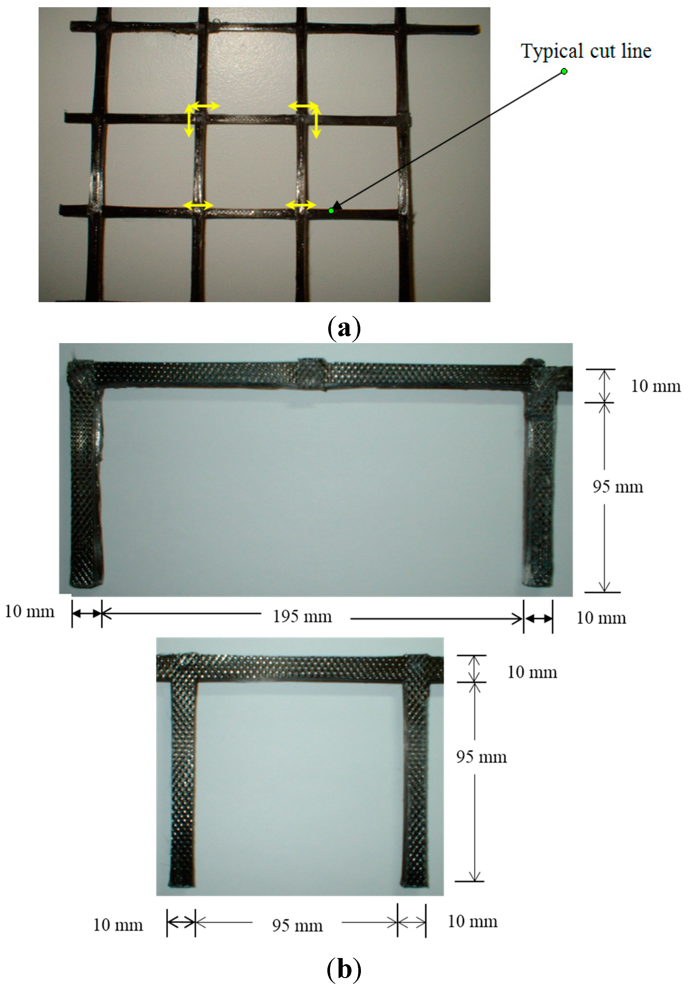
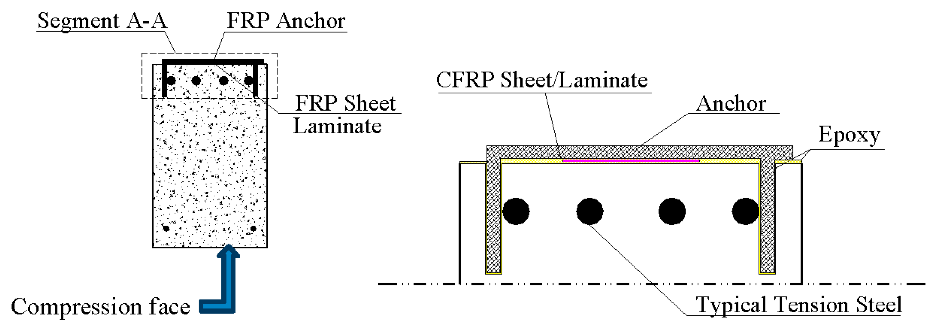
3. New C-Anchor Description

4. Experiential Program
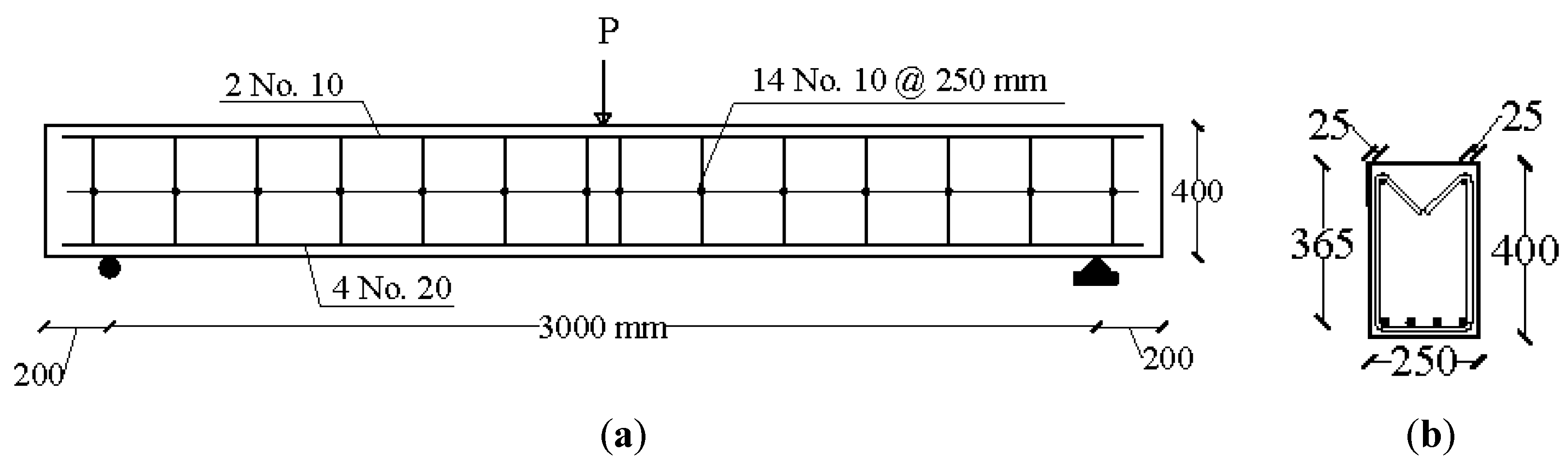
4.1. Test Specimens


| Properties | CFRP Laminate | Epoxy | CFRP Sheet | Primer | Saturant |
|---|---|---|---|---|---|
| Tensile strength (MPa) | 2800 | 46.8 | 3800 | 14.5 | 54 |
| Modulus of elasticity (GPa) | 165 | 4.5 | 227 | 0.717 | 3.034 |
| Ultimate strain (%) | 1.90 | 1.0 | 1.67 | 40 | 3.50 |
| Thickness (mm) | 1.2 | - | 0.165 per ply | - | - |
| Width (mm) | 50 | - | 610 | - | - |
| Type of CFRP | Beam | No. of Layers | Thickness per Layer | Width | Total Cross-Sectional Area |
|---|---|---|---|---|---|
| (mm) | (mm) | (mm2) | |||
| CB | 0 | - | - | - | |
| CFRP Laminate | LN100 | 1 | 1.2 | 100 | 120 |
| LA100 | 1 | 1.2 | 100 | 120 | |
| LN50 | 1 | 1.2 | 50 | 60 | |
| LA50 | 1 | 1.2 | 50 | 60 | |
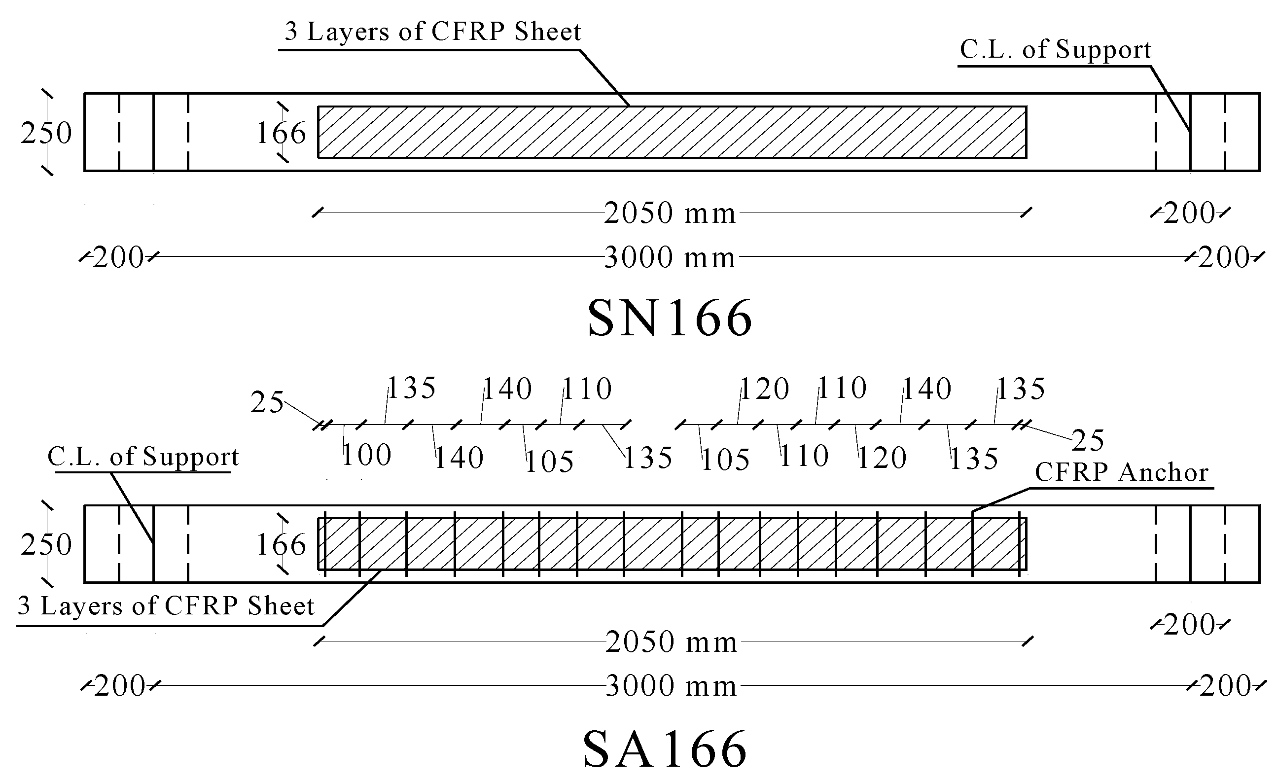
| CFRP Sheet | SN166 | 3 | 0.165 | 166 | 82.2 |
| SA166 | 3 | 0.165 | 166 | 82.2 | |
| SN83 | 3 | 0.165 | 83 | 41.1 | |
| SA83 | 3 | 0.165 | 83 | 41.1 |
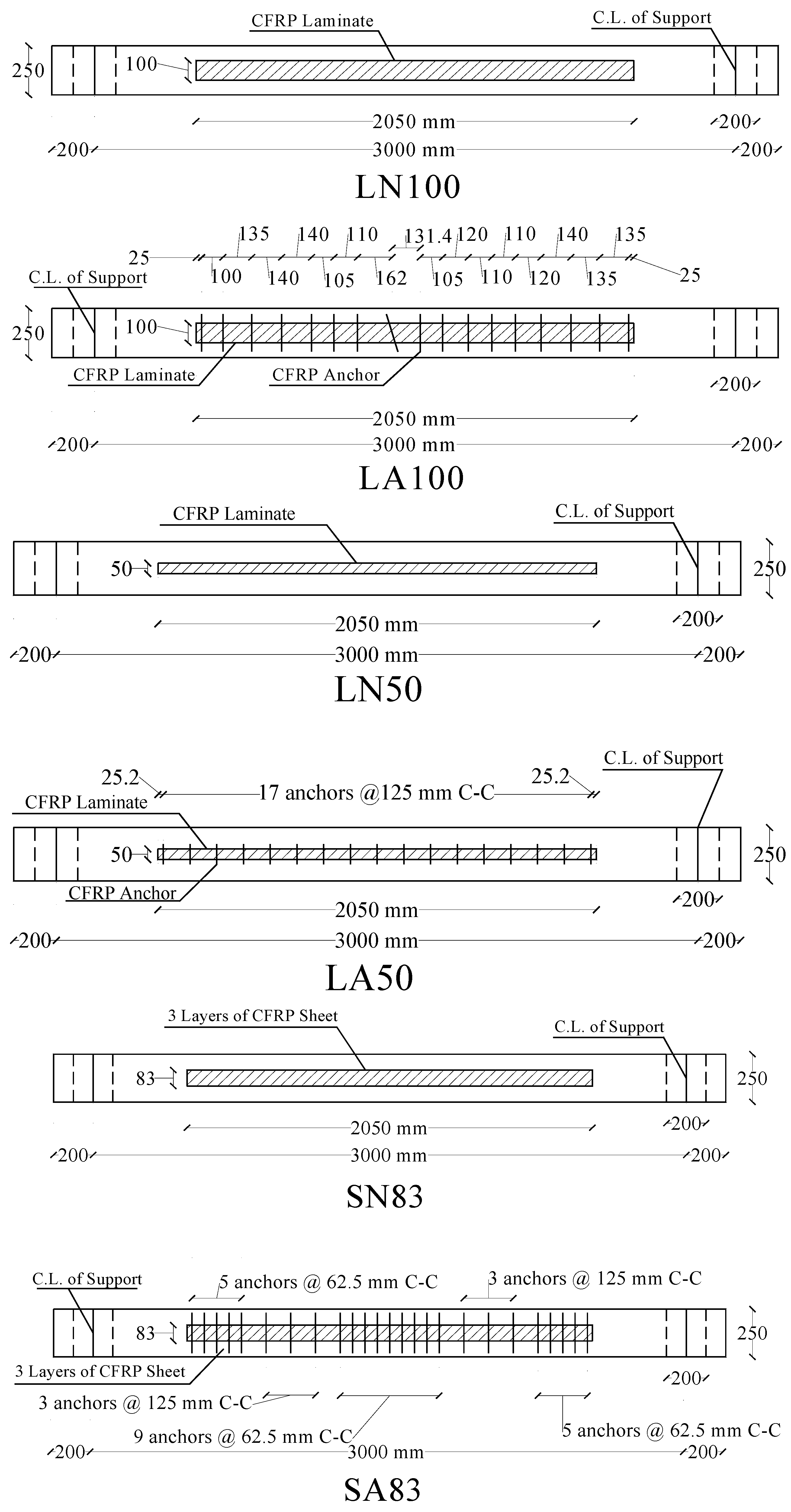

4.2. External Shear Reinforcement
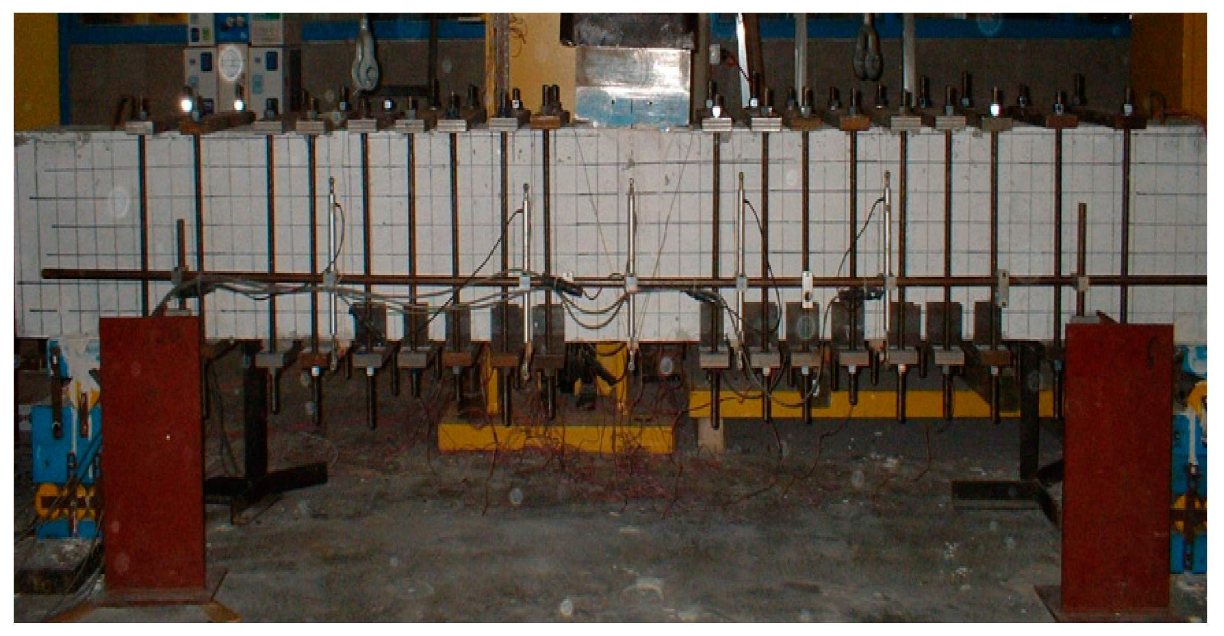
4.3. Instrumentation and Test Method

5. Results and Discussion
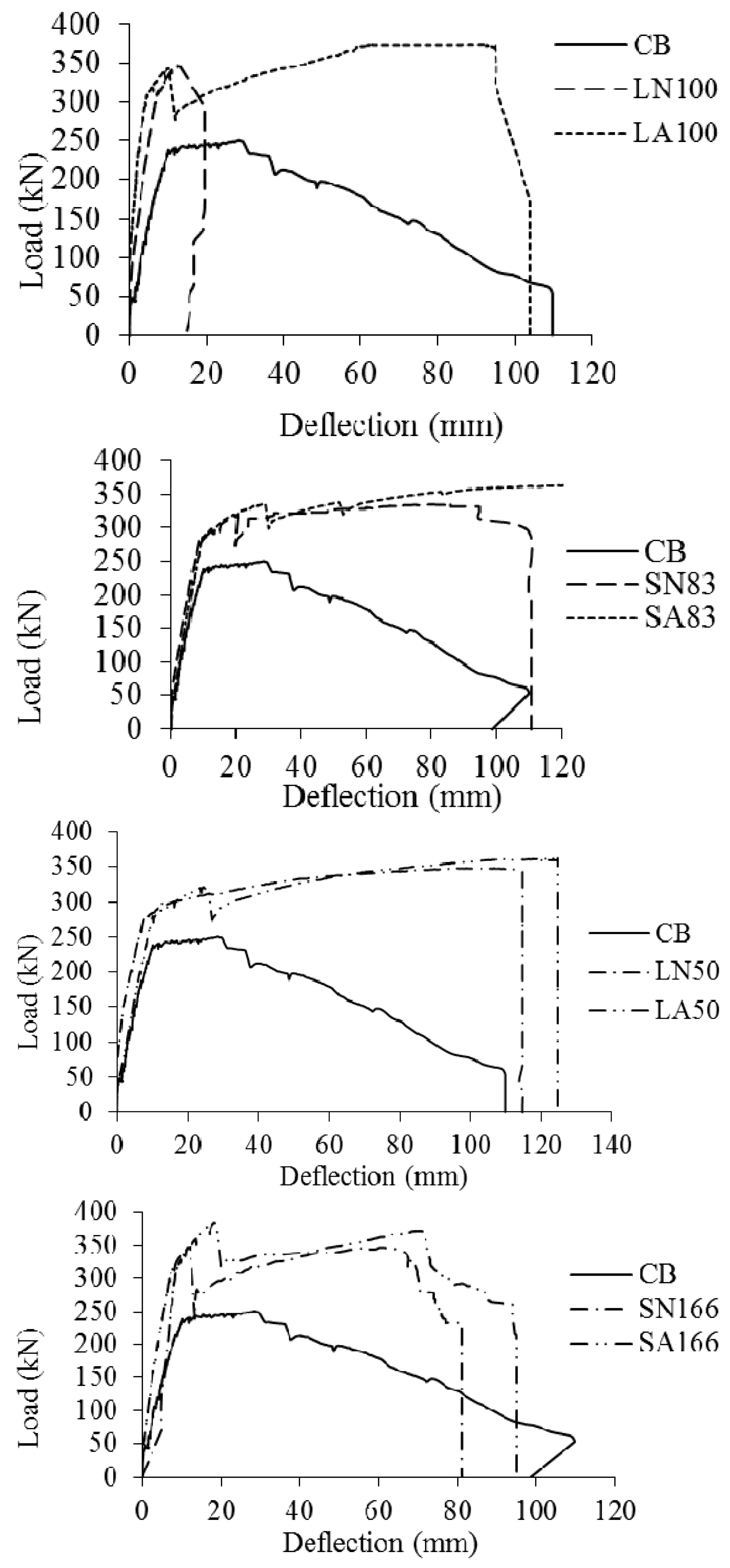
5.1. Load Deflection Behaviour
5.2. Ultimate Flexural Strength
| Beam | Theoretical Failure Moment, Mu (kN.m) | Experimental | |||
|---|---|---|---|---|---|
| Debonding Moment Mdb (kN.m) | Failure Moment MF (kN.m) | ||||
| CB | 180 | - | 187.9 | 1.00 | 1.04 |
| LN100 | 270 | 260.1 | - | - | - |
| LA100 | 257.0 | 279.6 | 1.49 | 1.04 | |
| SN166 | 263 | 260.0 | 244.7 | 1.30 | 0.93 |
| SA166 | 288.6 | 279.9 | 1.49 | 1.06 | |
| LN50 | 235 | 223.9 | 260.8 | 1.39 | 1.11 |
| LA50 | 240.9 | 271.9 | 1.45 | 1.16 | |
| SN83 | 232 | 237.7 | 250.8 | 1.33 | 1.08 |
| SA83 | 251.3 | 272.9 | 1.45 | 1.18 | |
5.3. Debonding Load
| Beam | Pdb (kN) | Pdrop (kN) | PF (kN) | ΔPdrop (kN) | ΔPdrop/Pdb (%) | PF/Pdb (%) |
|---|---|---|---|---|---|---|
| CB | - | - | 250.5 | - | - | - |
| LN100 | 346.8 | 293.8 | - | 53.0 | 15.3 | - |
| LA100 | 342.6 | 276.3 | 372.8 | 66.3 | 19.4 | 108.8 |
| SN166 | 346.8 | 245.5 | 326.2 | 101.3 | 29.2 | 94.1 |
| SA166 | 384.8 | 319.9 | 373.1 | 64.9 | 16.9 | 97.0 |
| LN50 | 298.5 | 262.6 | 347.7 | 35.9 | 12.0 | 116.5 |
| LA50 | 321.2 | 274.0 | 362.5 | 47.2 | 14.7 | 112.9 |
| SN83 | 316.9 | 273.4 | 334.4 | 43.5 | 13.7 | 105.5 |
| SA831 | 335.1 | 298.5 | 363.8 | 36.6 | 10.9 | 108.6 |
5.4. Load Drop after Debonding
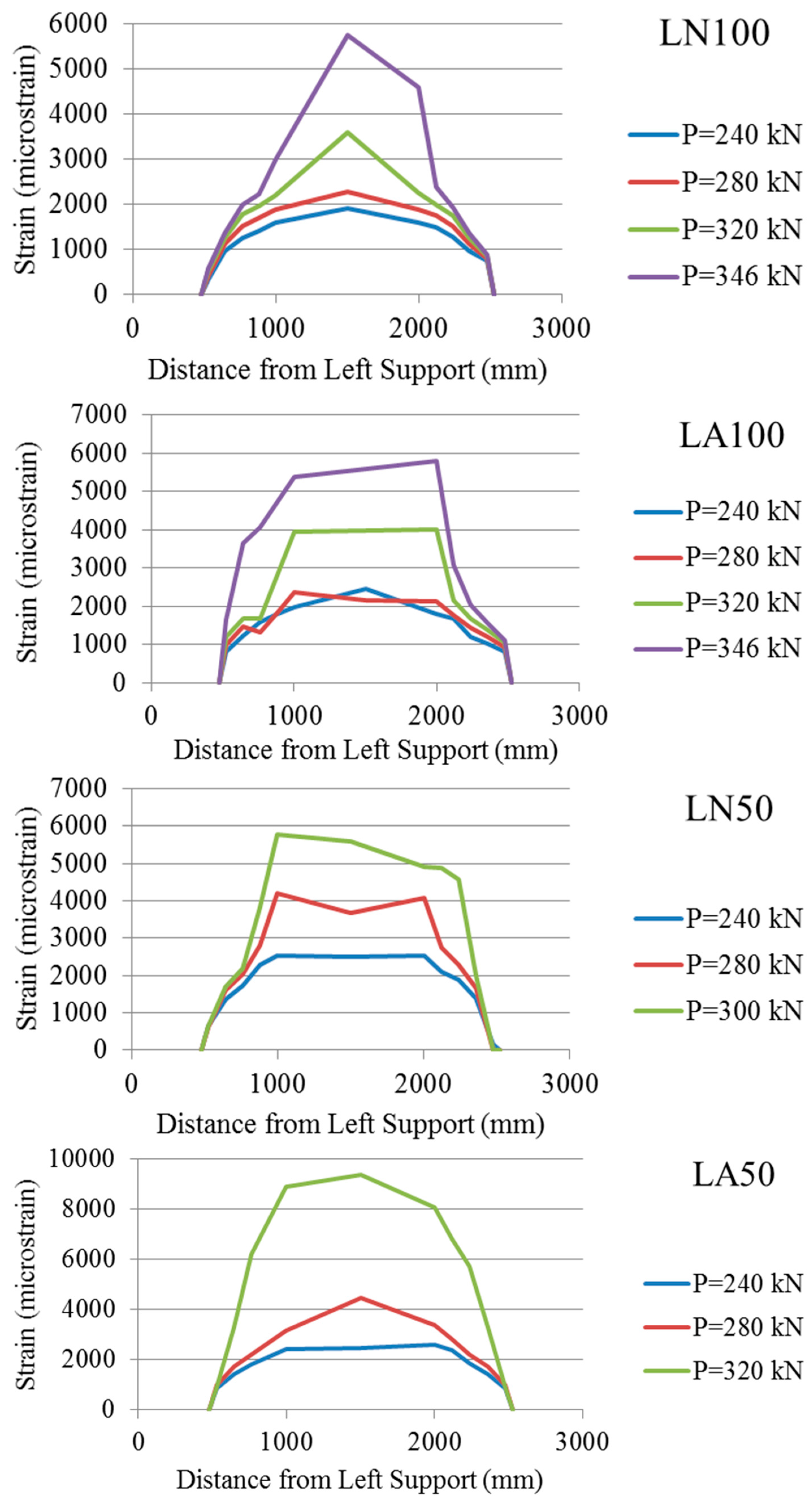
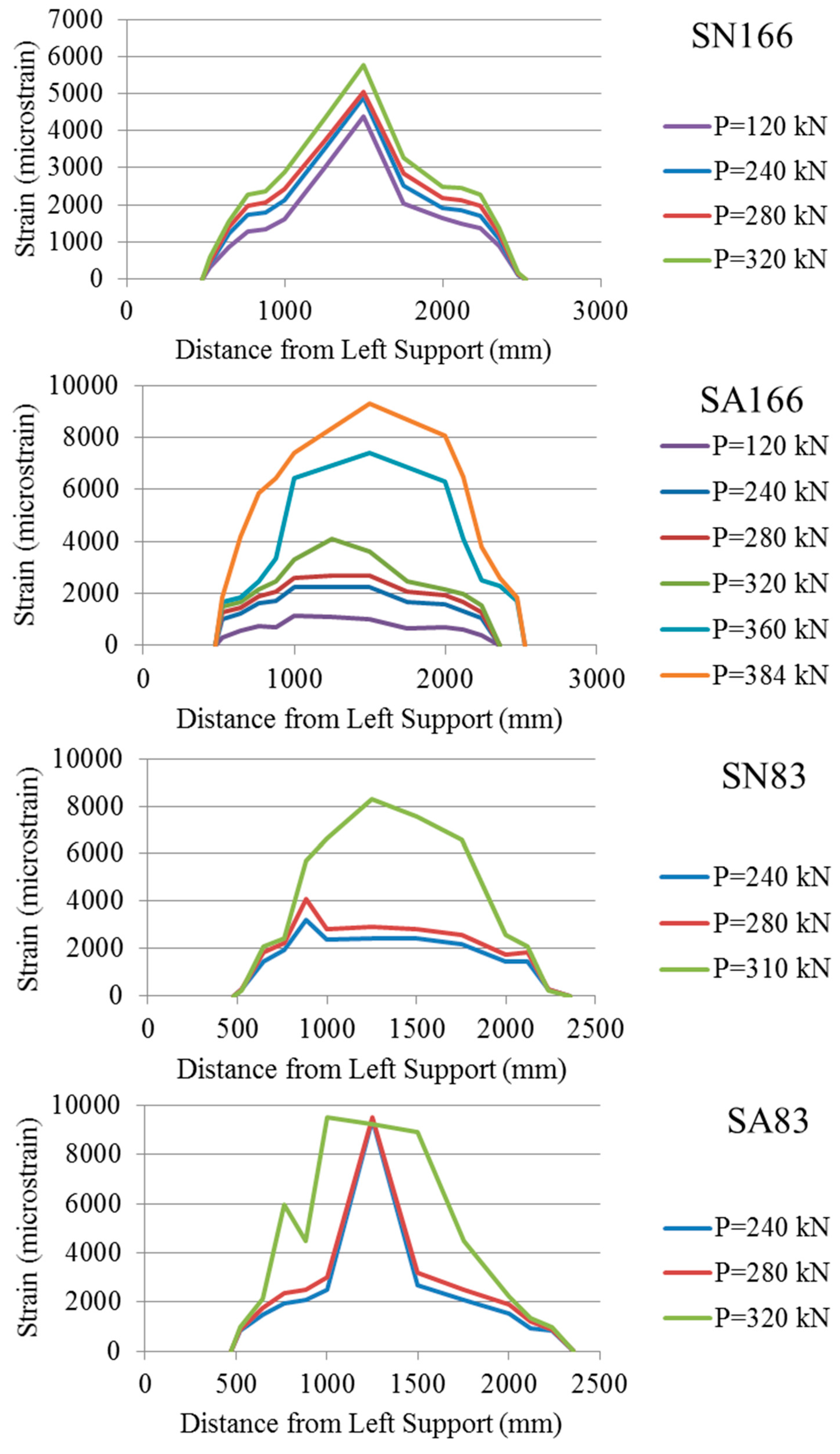
5.5. Strain Profile
5.6. Ductility and Energy Absorption
| Beam | Max. Load at Failure (kN) | Deflection at Debonding Load (mm) | Deflection at Failure Load (mm) | Ductility Index (μ) | Energy Absorbed (kN.m) | Energy Absorption Index (η) |
|---|---|---|---|---|---|---|
| CB | 212.5 | 29.6 * | 37.6 | 1.27 | 7.8 | 1.00 |
| LN100 | 344.5 | 13.2 | 13.2 | 1.00 | 3.3 | 0.43 |
| LA100 | 371.0 | 10.5 | 93.2 | 8.88 | 32.2 | 4.11 |
| SN166 | 342.0 | 12.2 | 65.6 | 5.38 | 19.2 | 2.45 |
| SA166 | 368.5 | 18.9 | 71.3 | 3.77 | 23.3 | 2.98 |
| LN50 | 338.1 | 9.2 | 114.4 | 12.43 | 36.4 | 4.65 |
| LA50 | 354.7 | 25.8 | 124.4 | 4.82 | 39.6 | 5.06 |
| SN83 | 328.1 | 20.1 | 94.8 | 4.72 | 29.1 | 3.71 |
| SA83 | 361.3 | 29.8 | 123.4 | 4.14 | 40.0 | 5.11 |
5.7. Maximum Strain Attained in FRP versus Its Rupture and Allowable Strains
| Beam Designation | Maximum Strain Recorded in FRP, εF (microstrain) | (microstrain) | Efficiency Factor = | |
|---|---|---|---|---|
| LN100 | 5750 | 6640 | 0.30 | 0.87 |
| LA100 | 5790 | 0.31 | 0.87 | |
| LN50 | 5760 | 0.30 | 0.87 | |
| LA50 | 9370 | 0.49 | 1.41 | |
| SN166 | 5760 | 8820 | 0.35 | 0.65 |
| SA166 | 9300 | 0.56 | 1.05 | |
| SN83 | 8320 | 0.50 | 0.94 | |
| SA83 | 9820 | 0.59 | 1.08 |
6. Conclusions
- (1)
- Beams outfitted with the proposed C-anchor had generally 5%–10% higher debonding load and reached higher maximum load and corresponding deflection than the companion beams without anchor.
- (2)
- Beams with anchor reached higher strain in the FRP compared to their companion beams without anchor and the maximum strain exceeded the theoretical strain based on the ACI 440 equation.
- (3)
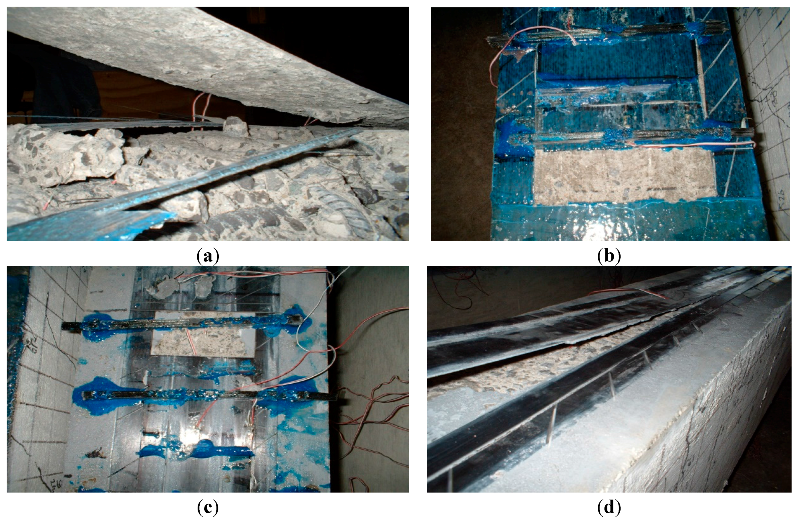
- Although complete separation of the laminate/sheet from the concrete was not observed in any of the beams with anchor, substantial slip was noticed at one end of the FRP laminate.
- (4)
- Despite the fact that some of the strengthened beams were over-reinforced, they failed in a ductile fashion because the failure was initiated by debonding and thereafter they reverted to their un-strengthened under-reinforced behavior.
- (5)
- The anchor was found to be effective in limiting the extent of debonding along the laminate, thus indirectly contributing to the beam flexural stiffness by limiting its crack width.
- (6)
- The anchor significantly increased the energy absorption or toughness of the strengthened beams, but further investigation is needed to optimize the number and location of the anchors.
- (7)
- The proposed C-anchor shows promise, but its performance can be improved by increasing its contact surface with the concrete and the FRP laminate. In other words, the anchor spine width needs to be much larger than its thickness in order to increase its surface area for resisting interfacial shear.
Acknowledgments
Author Contributions
Conflicts of Interest
References
- Teng, J.G.; Chen, J.F.; Smith, S.T.; Lam, L. FRP Strengthening RC Structures; John Wiley and Sons, Inc.: New York, NY, USA, 2002. [Google Scholar]
- Oehlers, D.J.; Seracino, R. Design of FRP and Steel Plated RC Structures; Elsevier: London, UK, 2004. [Google Scholar]
- Smith, S.T.; Teng, J.G. FRP strengthened RC beam. II assessment of debonding strength models. Eng. Struct. 2002, 24, 397–417. [Google Scholar] [CrossRef]
- Smith, S.T.; Teng, J.G. FRP-strengthened RC beams I: Review of debonding strength models. Eng. Struct. 2002, 24, 385–395. [Google Scholar] [CrossRef]
- Mostafa, A. Development of a New FRP Anchor for Externally Bonded CFRP Sheet/Laminate to Beams. Master’s Thesis, Carleton University, Ottawa, ON, Canada, 2005. [Google Scholar]
- Mostafa, A. A Novel FRP Anchor for Preventing Delamination in FRP Strengthened Concrete Beams. Ph.D. Thesis, McMaster University, Hamilton, ON, Canada, 2010. [Google Scholar]
- Mostafa, A.; Razaqpur, A.G. CFRP anchor for preventing premature debonding of externally bonded frp laminates from concrete. J. Compos. Constr. 2013, 17, 641–650. [Google Scholar] [CrossRef]
- CSA. Design and Construction of Building Components with Fiber-Reinforcement Polymers; CSA Standard S806–12; CSA: Rexdale (Toronto), ON, Canada, 2012. [Google Scholar]
- ACI Committee 440. 440.2R-08 Guide for the Design and Construction of Externally Bonded FRP Systems for Strengthening Concrete Structures; American Concrete Institute: Farmington Hills, MI, USA, 2008. [Google Scholar]
- Federation internationale du beton (fib). Design and Use of Externally Bonded Fiber Reinforced Polymer Reinforcement (FRP EBR) for Reinforced Concrete Structures; Technical Report, Bulletin No.14; International Federation for Structural Concrete (fib): Lausanne, Switzerland, 2011. [Google Scholar]
- Wu, Y.F.; Yan, J.H.; Zhou, Y.W.; Xia, Y. Ultimate strength of reinforced concrete beams retrofitted with hybrid bonded fiber-reinforced polymer. ACI Struct. J. 2010, 107, 451–460. [Google Scholar]
- Oller, E.; Salcedo, D.C.; Mari, A. Flexural strengthening of reinforced concrete beams with externally bonded CFRP laminates. In Proceedings of Conference on Composites in Construction, Porto, Portugal, 10–12 October 2001; Balkema Publishers; pp. 473–478.
- Kalfat, R.; Al-Mahaidi, R.; Smith, S.T. Anchorage devices used to improve the performance of reinforced concrete beams retrofitted with frp composites: A-state-of-the-art review. J. Compos. Constr. 2013, 17, 14–33. [Google Scholar] [CrossRef]
- Spadea, G.; Bencardino, F.; Swamy, R.N. Structural behavior of composite RC beams with externally bonded CFRP. J. Compos. Constr. 1998, 2, 132–137. [Google Scholar] [CrossRef]
- Lamanna, A.J.; Bank, L.C.; Scott, D.W. Flexural strengthening of RC beams using fasteners and FRP strips. ACI Struct. J. 2001, 93, 368–376. [Google Scholar]
- Martin, J.; Lamanna, A. Performance of mechanically fastened FRP strengthened concrete beams in flexure. J. Compos. Constr. 2008, 12, 257–265. [Google Scholar] [CrossRef]
- Elsayed, W.; Ebead, U.; Neale, K. Studies on mechanically fastened fiber-reinforced polymer strengthening systems. ACI Struct. J. 2009, 106, 49–59. [Google Scholar]
- Teng, J.G.; Lam, L. Strengthen of RC cantilever slabs bonded with gfrp strips. J. Compos. Constr. 2001, 5, 221–227. [Google Scholar]
- Smith, S.T.; Kim, S.J. Shear Strength and Behavior of FRP Spike Anchors in FRP-to-Concrete Joint Assemblies, Proceedings of the 5th International Conference on Advanced Composite Materials in Bridges and Structures 2008 (ACMBS-V 2008), Winnipeg, MB, Canada, 22–24 July 2008; Canadian Society for Civil Engineering: Montreal, QC, Canada, 2008.
- Ceroni, F.; Pecce, M.; Matthys, S.; Taerwe, L. Debonding strength and anchorage devices for reinforced concrete elements strengthened with frp sheet. Compos. Part B Eng. 2008, 39, 429–441. [Google Scholar] [CrossRef]
- Orton, S.L.; Jirsa, J.O.; Bayrak, O. Design consideration of carbon fiber anchors. J. Compos. Constr. 2008, 12, 608–616. [Google Scholar] [CrossRef]
- Smith, S.T. FRP Anchors: Recent Advances in Research and Understanding, Proceedings of the 2nd International Conference on FRP in Structures—APFIS 2009, Seoul, Korea, 9–11 December 2009.
- Pham, L.; Jirsa, J.O.; Bayrak, O. Development of quality control tests for CFRP anchors. In Proceedings of the 9th International Symposium of the Fiber-Reinforced Polymer Reinforcement for Reinforced Concrete Structures (FRPRCS-9), Sydney, Australia, 13–15 July 2009.
- Micelli, F.; Rizzo, A.; Galati, D. Anchorage of composite laminates in rc flexural beams. Struct. Concr. 2010, 11, 117–126. [Google Scholar]
- Smith, S.T.; Teng, J.G. Shear-bending interaction in debonding failures of FRP-plated RC beams. Adv. Struct. Eng. 2003, 6, 183–199. [Google Scholar] [CrossRef]
- Pham, H.B.; Al-Mahaidi, R. Prediction models for debonding failure loads of carbon fiber reinforced polymer retrofitted reinforced concrete beams. J. Compos. Constr. 2006, 10, 48–59. [Google Scholar] [CrossRef]
- Razaqpur, A.G.; Mostafa, A. A new CFRP anchor for preventing separation of externally bonded laminates from concrete. In Proceedings of the 4th International Conference on the on Construction Materials, Nagoya, Japan, 24–26 August 2009.
- Swamy, R.N.; Jones, R.; Bloxham, J.W. Structural behavior of reinforced concrete beams strengthened by epoxy-bonded steel plates. Struct. Eng. 1987, 65, 59–68. [Google Scholar]
- Takahashi, Y.; Sato, Y.; Ueda, T.; Maaeda, T.; Kobayashi, A. Flexural Behavior of RC Beams with Externally Bonded Carbon Fiber Sheet, Proceedings of the 3rd International Symposium on non-Metallic (FRP) Reinforcement for Concrete Structures (FRPRCS-3), Sapporo, Japan, 14–16 October 1997; Japan Concrete Institute: Tokyo, Japan, 1997; Volume 1, pp. 327–334.
- Poulsen, E.; Bendtsen, L.; Mortensen, J.; Ottosen, N.S. Anchorage and Laps of CFRP Strips for the Strengthening of RC Structural Components, Proceedings of Composite in Construction, Porto, Portugal, 10–12 October 2001; Balkema Publishers: Leiden, The Netherlands, 2001; pp. 205–209.
- Meier, U. Strengthening of structures using carbon fiber/epoxy composites. Constr. Build. Mater. 1995, 9, 341–351. [Google Scholar] [CrossRef]
- SIKA Carbodur. Engineering Guidelines for the use of Sika CarboDur (CFRP) Laminate for Structural Strengthening of Concrete Structures; Sika Corporation: Lyndhurst, NJ, USA, 1997. [Google Scholar]
- Ali, A.; Abdalla, J.; Hawileh, R.; Gala, K. CFRP mechanical anchorage for externally strengthened RC beams under flexural. Phys. Procedia 2014, 55, 10–16. [Google Scholar] [CrossRef]
- Zaghloul, A. Behavior and Strength of CFRP Reinforced Flat Plate Interior Column Connections Subjected to Shear and Unbalanced Moments. Master’s Thesis, Carleton University, Ottawa, ON, Canada, 2002. [Google Scholar]
- Cement Association of Canada. Concrete Design Handbook, 3rd ed.; Cement Association of Canada: Ottawa, ON, Canada, 2005.
© 2015 by the authors; licensee MDPI, Basel, Switzerland. This article is an open access article distributed under the terms and conditions of the Creative Commons Attribution license (http://creativecommons.org/licenses/by/4.0/).
Share and Cite
Razaqpur, G.; Mostafa, A.B. C-Anchor for Strengthening the Connection between Adhesively Bonded Laminates and Concrete Substrates. Technologies 2015, 3, 238-258. https://doi.org/10.3390/technologies3040238
Razaqpur G, Mostafa AB. C-Anchor for Strengthening the Connection between Adhesively Bonded Laminates and Concrete Substrates. Technologies. 2015; 3(4):238-258. https://doi.org/10.3390/technologies3040238
Chicago/Turabian StyleRazaqpur, Ghani, and Ahmed B. Mostafa. 2015. "C-Anchor for Strengthening the Connection between Adhesively Bonded Laminates and Concrete Substrates" Technologies 3, no. 4: 238-258. https://doi.org/10.3390/technologies3040238
APA StyleRazaqpur, G., & Mostafa, A. B. (2015). C-Anchor for Strengthening the Connection between Adhesively Bonded Laminates and Concrete Substrates. Technologies, 3(4), 238-258. https://doi.org/10.3390/technologies3040238