Concept Paper

C-Anchor for Strengthening the Connection between Adhesively Bonded Laminates and Concrete Substrates

by
Ghani Razaqpur
1 and
Ahmed B. Mostafa
2,3,*
1
Department of Civil Engineering, McMaster University, Hamilton, ON L8S 4L7, Canada
2
TemCorp Industries LTD, Stoney Creek, ON L8E 5M3, Canada
3
Department of Civil Engineering, Ryerson University, Toronto, ON M5B 2K3, Canada
*
Author to whom correspondence should be addressed.
Technologies 2015, 3(4), 238-258; https://doi.org/10.3390/technologies3040238
Submission received: 2 November 2015 / Revised: 20 November 2015 / Accepted: 23 November 2015 / Published: 30 November 2015
(This article belongs to the Special Issue Bolted and Bonded Joints in Fibre Reinforced Polymer Structures)

Abstract

:
A new carbon fiber reinforced polymer (CFRP) anchor is developed and tested to delay debonding in reinforced concrete (RC) beams externally strengthened with FRP laminate/sheet. The C-shape anchor is made from a commercially available CFRP grid. The anchors legs are 95 mm long while the spacing between the legs is adjustable, depending on FRP laminate and beam widths. Nine full scale RC beams, 3.0 m long, 250 mm wide and 400 mm deep, were strengthened with CFRP laminate/sheet, with and without the C-anchor. The main test parameters were the type and amount of FRP laminate and the presence/absence of the anchor. Test results showed that beams with the anchor had generally 5%–10% higher debonding and failure load, and they reached higher deflection at failure than the companion beams without anchors. Although complete separation of the FRP laminate from the concrete was not observed in any of the beams with anchors, there was noticeable slip at failure at one end of the laminate. A significant outcome of the study is that anchors are effective in limiting the extent of debonding along the laminate, thus contributing to the flexural stiffness of the beam by reducing the extent of cracking and limiting the crack width along the beam. Finally, the anchor allowed the FRP to reach or exceed its theoretically allowable strain computed based on the American Concrete Institute (ACI) Committee 440 recommendation while in none of the beams without anchors, the FRP reached its theoretically allowable strain.

1. Introduction

The need for new strengthening techniques has emerged as a result of increased live load on bridges over the past few decades or due to more stringent design requirements for earthquake and other severe loads acting on structures. The effective and expedient rehabilitation of structures exposed to severe environments is yet another major concern in many countries. For economic reasons, it is not possible to replace all the deteriorated or functionally impaired structures with new structures; therefore, the need for rehabilitation and retrofit of these structures exists. The use of fiber reinforced polymers (FRP) for strengthening and rehabilitation of reinforced concrete (RC) structures has been steadily growing. The advantages of using FRP include ease of application, high ultimate strength, resistance to corrosion—corrosion being the principal cause of deterioration of bridges and parking structures in North America—and ease of application compared to other repair techniques [1,2,3,4]. It has been demonstrated experimentally that the maximum capacity of RC beams externally reinforced with FRP sheet/laminate cannot always be fully achieved due to premature debonding of the FRP from the concrete substrate [5,6,7]. The main premature failure modes in the case of flexural strengthening are: FRP debonding caused by intermediate flexural cracks, FRP debonding in the vicinity of flexural-shear cracks, FRP debonding caused by high normal and shear stresses near the laminate ends, and delamination of concrete cover over the main tensile reinforcement. Premature failure prevents the strengthened beam to reach its theoretical ultimate capacity based on full bond assumption. Failure initiated by debonding is generally difficult to predict, with intermediate crack (IC) induced debonding being particularly challenging. This form of debonding is generally triggered by complex local stresses developed at the laminate-concrete interface in the vicinity of flexural or flexural-shear cracks and the ensuing debonding is sudden and brittle. Some design guidelines [8,9,10], as well as some researchers [11] provide equations for estimating the maximum useable strain in FRP laminates bonded to concrete for flexural strengthening. However, Mostafa and Razaqpur [7] showed that these equations overestimate the strain in the case of laminates made of several plies. Oller et al. [12] also found that 0.6%–0.8% strain predicted by these equations may be too high in some cases, for none of the beams they tested could exceed 0.5% strain before debonding. Therefore, they recommended the use of anchors to delay the debonding of FRP plates.
In practical design, it would be more advantageous to avoid the brittle mode of failure by either completely eliminating it or by changing it to a relatively ductile mode. A practical method for achieving this may be the anchoring of the laminate to the concrete substrate using metallic or FRP anchors. The disadvantage of metallic anchors is their susceptibility to corrosion, a phenomenon which can be avoided by using FRP anchors. The architecture and appropriate placement of an effective anchor system has been the subject of many studies in the past [6,7,11,13,14,15,16,17,18,19,20,21,22,23,24,25,26,27], with various levels of success in performance. The objective of this study is to investigate the performance of a new CFRP anchor, termed C-anchor, and to determine its effectiveness in preventing IC debonding and/or render the debonding process gradual and less brittle. The advantage of the proposed anchor over existing anchors is that it can be easily made in different configurations from an existing CFRP grid.

2. FRP Plate Anchoring Systems

A number of studies have investigated different mechanical techniques to prevent premature debonding. Swamy et al. [28] used steel plates near the ends of the externally bonded FRP laminate, and sandwiched the laminate between the beam soffit and the steel plates, with the steel plates anchored into the concrete by steel bolts. The use of steel plates and bolts as anchorage device is problematic due to their susceptibility to corrosion and the heavy weight of steel plates. Furthermore, excessive slippage at the laminate-steel plate interface has been reported in most cases. Lamanna et al. [15] used mechanical fasteners without any adhesive to attach CFRP strips to the bottom of concrete beams. They discovered that, due to the presence of the fasteners, cracks developed in concrete; consequently, the strengthened beams did not achieve their expected ultimate moment capacity.
A more popular method of anchorage is FRP U-jacket. The U-jacket is made of FRP sheet and applied to the bottom and sides of the beam in the anchorage zone. It has been reported by Takahashi et al. [29] that the presence of U-jacket can increase the longitudinal FRP laminate resistance to debonding, and by appropriate selection of the anchor system, it can change the failure mode from debonding to FRP rupture. However, they reported that the U-jacket did not increase the ultimate moment capacity of strengthened beams compared to similarly strengthened beams without U-jacket, but it enabled the beam to undergo up to 50% more deformation before failure, which confirms the findings of Swamy et al. [28] with respect to the benefit of steel plate anchorage. In other words, these anchor systems prevent sudden debonding and abrupt drop in the strengthened beam capacity without necessarily increasing the strengthened beam capacity compared to the strengthened beam without anchor. Oller et al. [12] tested beams with equally spaced U-jackets throughout the length of the beam. They reported that in the case of the beams with U-jacket, despite debonding and some slippage, they failed at 34.6% higher load than the unstrengthened control beam and at 9% higher load than similarly strengthened beams without anchors. It is clear that the strength increase was modest.
Ceroni et al. (2008) [20] reviewed available anchorage systems including fan anchor, an anchor system referenced in fib bulletin 14 [10] and U-jacket. It was reported that distributing the U-jackets evenly along the span will increase the strength and ductility of the strengthened member. Local slippage, rupture or debonding, accompanied by loss of effectiveness before reaching the tensile strength at mid-span, might be observed if the U-jackets are concentrated at the ends only. They also discussed steel U-shaped devices and they reported that this method increased ductility by allowing the member to experience higher displacement at ultimate state. Fan or spike anchors have been used in a number of investigations [18,19] The anchor is made of a CFRP tow and acts similar to a nail with a thin round head and a shank formed by the bundled tow that is inserted inside epoxy-filled predrilled holes in the concrete.
Martin and Lamanna [16] used mechanical steel screws to prevent debonding. In the study, the spacing and the pattern of the screws were investigated. Test results showed that using this method can increase the flexural capacity and stiffness of reinforced concrete beams 10%–39%. Elsayed et al. [17] conducted an investigation similar to Martin and Lamanna [16] by performing a series of direct shear tests to establish the governing parameters that affect the interfacial stresses of glass fiber reinforced polymer (GFRP) and CFRP strips mechanically fastened to concrete. They considered two types of fasteners: shot (rivet) and screw, with different arrangements and spacing. Pullout of the shot fastener was reported due to the cracks developed at the location of the fastener which weakened the surrounding concrete and the governing mode of failure was reported as bearing failure and pullout. On the other hand, the screw fasteners were more efficient as they did not damage the concrete or the FRP strip. The failure mode was bearing failure in the FRP strip which switched to rupture of FRP as the number of anchors increased.
Orton et al. [21] reviewed the previous anchorage systems and performed an experimental investigation to obtain the initial design parameters for anchors. They recommended using an anchor with a cross sectional area at least double the longitudinal FRP laminate cross section and distributing the anchors evenly along the span length. Furthermore, they stated that the anchor leg should be inserted inside the concrete at least to a depth of 130–150 mm to prevent its pull-out. To account for premature debonding, Poulsen et al. [30] discussed other methods of anchorage applied by Meier [31], including transverse strips bonded to the beam soffit and to the FRP plate, as well as anchoring of FRP at its ends. Although most of the above methods of anchoring have been shown to lead to somewhat ductile failure and higher strength compared to companion beams without anchor, failure is still generally initiated by debonding of the FRP laminate.
In light of the above discussion, the need for anchorage exists, but it would be ideal if an FRP anchor could be developed which could be used in any situation where the need for anchoring exists. Currently, the fan, or spike, anchor system is one such system [32]. The anchor is inserted in pre-drilled holes in concrete through the laminate or the FRP sheet fibers are moved to the side to pass the anchor shank through it. Both methods of inserting the anchor through the FRP cause reduction in the effective FRP area resisting tension. In addition, the anchor relies on the through thickness bearing strength of the laminate/sheet to transfer shear from the FRP to the concrete substrate. In case of thin laminates, such as FRP sheets, the bearing strength is going to be small and would limit the effectiveness of the anchor. This behavior is demonstrated by the experimental work performed by Ali et al. [33] where the spike anchor in a beam strengthened with CFRP sheet increased the beam strength by only 9%, compared to the companion beam without anchor, while in another beam strengthened with CFRP plate, the anchor increased the strength by 20%, compared to the companion beam without anchor. The proposed C-anchor does not pierce through the laminate, hence causes no reduction in the effective laminate cross-section; instead, it relies on the anchor spine to transfer the load by interfacial shear. The anchor is made from a commercially available CFRP grid and the availability of this grid, its ease of installation and the better quality control applied in its manufacturing are some of its advantages over the so-called fan or spike anchor. The objective of the investigation is to examine its effectiveness with respect to preventing premature and/or brittle debonding of the laminate from the concrete substrate.

3. New C-Anchor Description

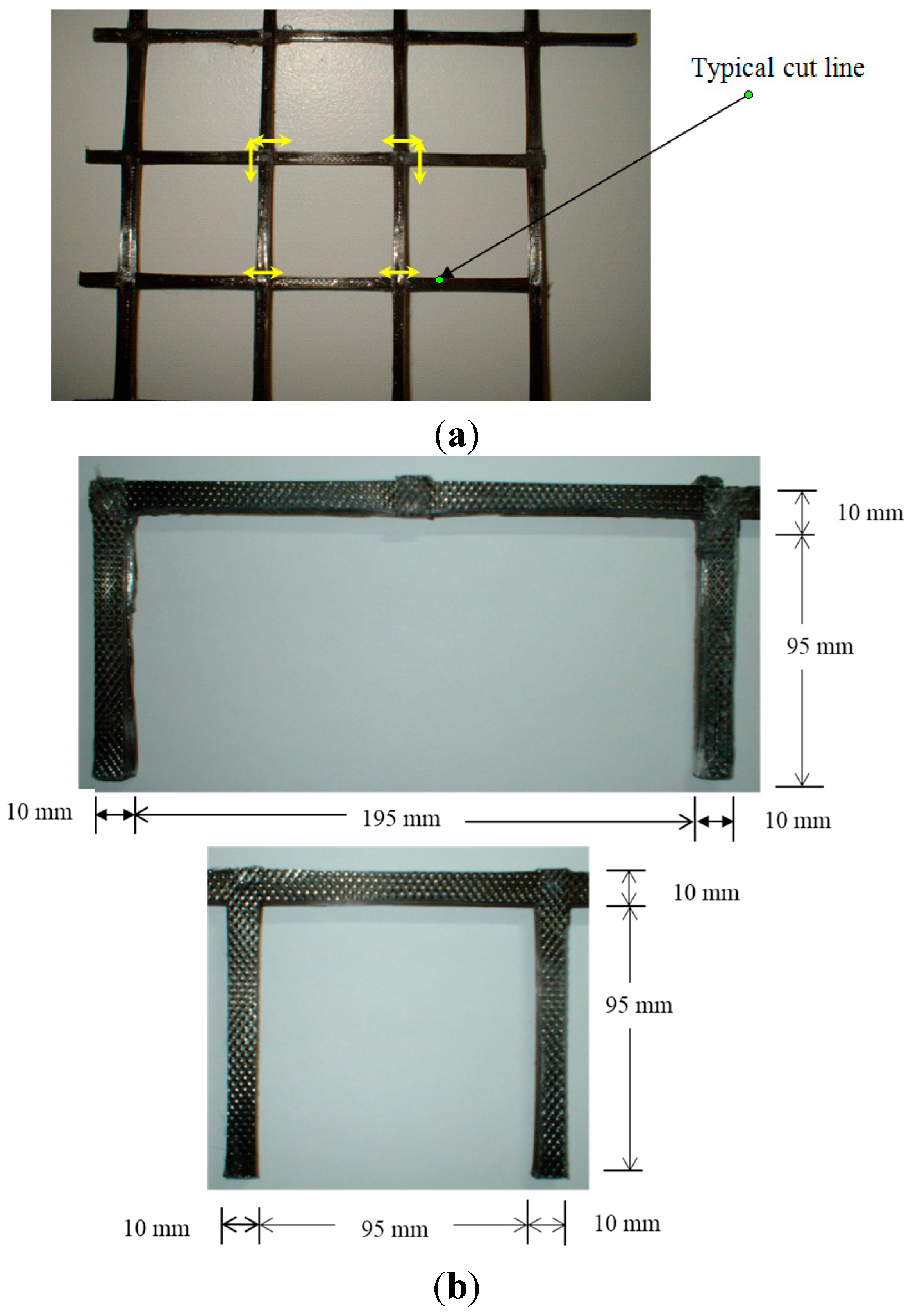
The proposed anchor was made by cutting the ribs of a commercially available CFRP grid and making it into a C or Π shape. Figure 1a shows the grid, with the cut lines as indicated, while Figure 1b illustrates possible anchor shapes. The grid ribs have 10 × 10 mm2 cross-sectional area with a rough surface finish. This grid has been extensively tested by both its manufacturer and by other investigators [34] to determine its mechanical properties. Its guaranteed tensile strength is 1200 MPa and its elastic modulus is 100 GPa. Due to its rough surface finish, it bonds very well with both concrete and the epoxy adhesive.
Figure 1. Typical CFRP grid and the proposed anchor. (a) CFRP grid; (b) Typical anchor shapes.
Technologies 03 00238 g001

4. Experiential Program

4.1. Test Specimens

Nine rectangular RC beams, 400 mm deep, 250 mm wide and 3.4 m long, were externally strengthened with CFRP laminate/sheet and were tested under three-point bending. A primer and a two part epoxy adhesive were used to bond the CFRP to the concrete surface. The 28 day concrete compressive strength was 52 MPa with its corresponding split cylinder tensile strength was 4 MPa. Each beam was reinforced with four 3.3 m long No.20 (φ = 19.5 mm) deformed bars in tension and two No. 10 (φ = 11.3 mm) deformed bars in compression. Figure 2 shows the typical beam elevation, cross-section, reinforcement and load configuration. Ancillary tensile tests were performed on the steel rebars to determine their tensile properties. The tests gave the following average values: fy = yield stress = 440 MPa, εy = strain at yield = 0.0022, Es = modulus of elasticity of steel = 200 GPa, fu = ultimate strength = 680 MPa, εu = ultimate strain = 0.056 and εsh = strain corresponding to the beginning of strain hardening = 0.007. For the CFRP materials used in the current study, Table 1 shows the properties of the CFRP sheet and laminate, the primer and the two part epoxy adhesive as reported by their manufactures.
Figure 2. Typical beam dimensions, reinforcement and load configuration. (a) elevation; (b) cross-Section.
Technologies 03 00238 g002
For easy identification of the beams with different characteristics, the following notation will be used: CB designates control beam, L designates beams strengthened with CFRP laminate plate, S with CFRP sheet, N indicates absence of anchor and A presence of anchor in the beam. The numbers 50 and 100 refer to the width in mm of the CFRP laminate while 83 and 166 refer to the width in mm of the CFRP sheet used to strengthen the beams. For example, LN50 refers to a beam strengthened with 50 mm wide CFRP laminate without anchor. Note that the holes for inserting the anchor legs were drilled into the concrete adjacent to the FRP but not into the FRP because the holes through FRP would damage the fibers and reduce the FRP cross-sectional area.
Table 1. Manufacturers’ specified properties of the carbon fiber reinforced polymer (CFRP) composites, primer and epoxy used in the current study.
PropertiesCFRP LaminateEpoxyCFRP SheetPrimerSaturant
Tensile strength (MPa)280046.8380014.554
Modulus of elasticity (GPa)1654.52270.7173.034
Ultimate strain (%)1.901.01.67403.50
Thickness (mm)1.2-0.165 per ply--
Width (mm)50-610--
Since the strengthened beams are tested in three-point bending, based on conventional design, the anchor spacing must be uniform because the beam is subjected to constant shear. However, at FRP-concrete interface, the stresses causing debonding also involve normal stresses and stress concentration near the ends of the FRP laminates/sheets. Due to the preliminary nature of the current investigation and the fact that concrete cracking and nonlinearity can lead to more complex stress distribution than that predicted by elastic theory, it is not feasible to arrive at precise spacing for the anchors. Furthermore, the anchor spacing is also dictated by the presence of the internal steel reinforcement because an anchor leg cannot be inserted where a stirrup is located or directly above a longitudinal steel rebar. Consequently, the spacing used was based mainly on practical considerations. Table 2 summarizes the number of layers, thickness and width of CFRP laminate/sheet used in the test beams.
Table 2. CFRP laminate and sheet dimensions used to strengthen the test beams.
Type of CFRPBeamNo. of LayersThickness per LayerWidthTotal Cross-Sectional Area
(mm)(mm)(mm2)
CB0---
CFRP LaminateLN10011.2100120
LA10011.2100120
LN5011.25060
LA5011.25060
CFRP SheetSN16630.16516682.2
SA16630.16516682.2
SN8330.1658341.1
SA8330.1658341.1
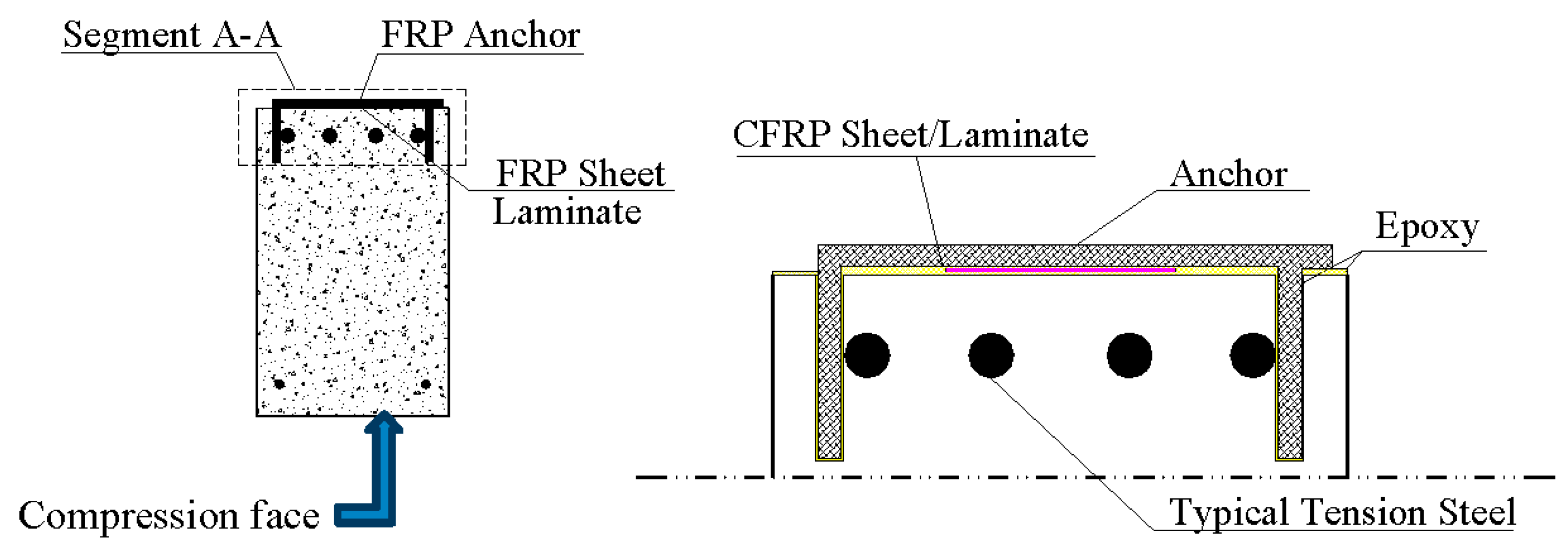
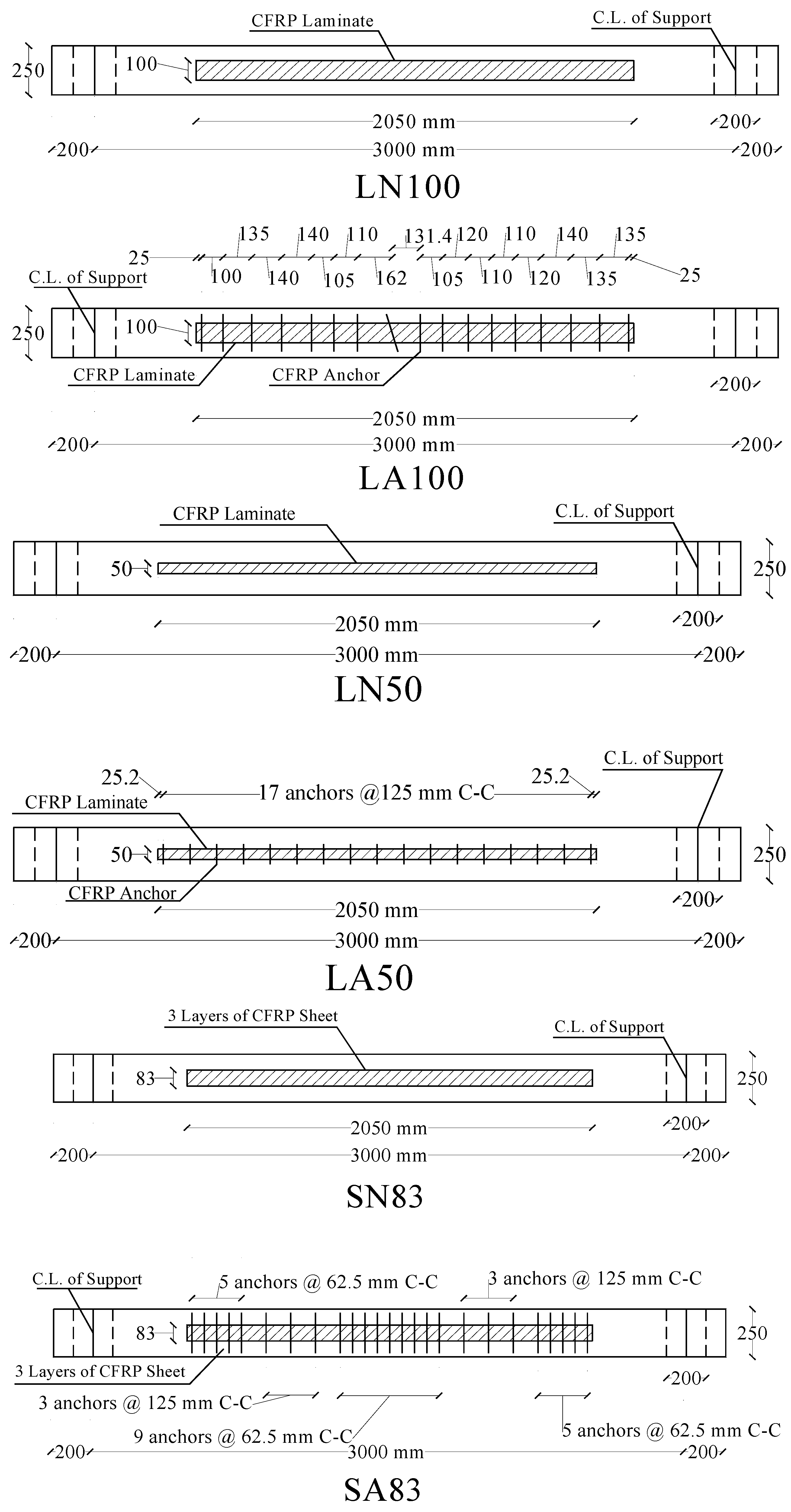
One of the nine beams was used as control beam (CB) and was not strengthened while the remaining eight beams were strengthened with different amounts of one of the two types of CFRP specified in Table 1 and outfitted with different anchor arrangements. The anchors were inserted into pre-drilled holes on the tension face of each beam. Figure 3 illustrates the position of a typical anchor in the cross-section and an enlarged view of segment A-A. Figure 4 shows the location of the anchors in the relevant beams.
Figure 3. Details of the strengthened beam cross-section with anchor.
Technologies 03 00238 g003
Figure 4. Plan view of tension face of the strengthened beams and their anchor arrangement.
Technologies 03 00238 g004aTechnologies 03 00238 g004b
The FRP laminates used in this study are available in 50 mm wide strips. Hence, in this study, either one or two strips were used to strengthen the beams. The two strips were applied side by side rather than on top of each other. The FRP sheets are available in wider sizes, but, in this study, either 166.7 mm or 83.3 mm wide swatches were cut from the wider rolls and bonded to the concrete surface. To achieve the same level of flexural strength as the beams strengthened with the laminate, three plies of the sheet were stacked on top of each other and bonded to each beam. It may be noticed in the latter figures that the external reinforcement is not extended to the ends of the beams, which is normally the practice. The reason is that extension to ends may retard debonding, in which case the effect of the anchor cannot be determined. Therefore, only a nominal development length was provided in order to encourage debonding. The development length is measured from the theoretical cut-off point to the end of the FRP sheet/laminate. The theoretical cut-off point is at the section at which the un-strengthened beam capacity is equal to the applied moment acting on that section at failure.

4.2. External Shear Reinforcement

The beams were originally designed for 40 MPa concrete and both their flexural and shear strength were accordingly determined. However, the ready mix concrete delivered had a 28-day compressive strength in excess of 50 MPa. Since the strengthened beams were over-reinforced, and since the flexural capacity of an over-reinforced beam is directly proportional to the concrete strength, the actual flexural capacity of the test beams surpassed their design capacity by a wide margin. On the other hand, since the shear capacity of a beam is a function of the square root of concrete strength, their shear capacity did increase to the same extent as their flexural capacity. This change in the two capacities created the possibility of shear failure in the beams prior to flexural failure. To prevent this from happening, it was decided to use external stirrups as additional shear reinforcement. It is believed that the presence of this reinforcement will not affect the flexural behavior and strength of the beams or the contribution of the FRP external reinforcement. In placing the external stirrups, it was made certain that they did not come in contact with the FRP sheet/laminate.

4.3. Instrumentation and Test Method

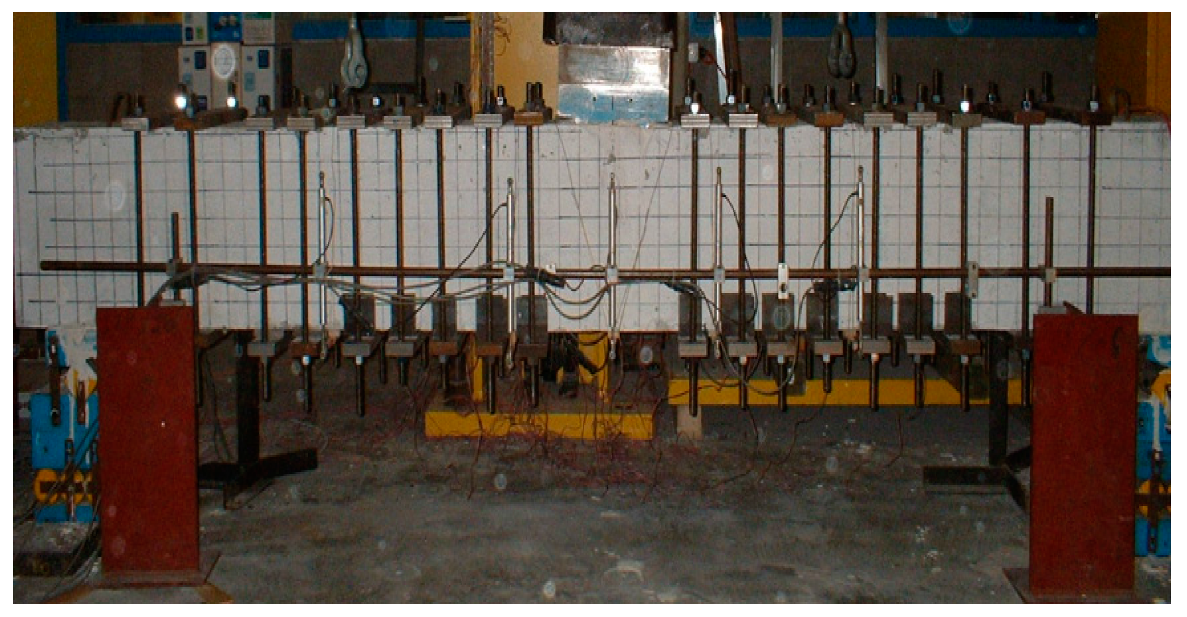
All the strengthened beams were loaded in three-point bending as shown in Figure 5. The beams were loaded in displacement control using a servo-controlled hydraulic actuator with a load cell. Electrical resistance strain gauges were attached to the CFRP sheet/laminate surface as well as the concrete and the internal tension reinforcement to measure the relevant strains. The beam deformation was measured using 10 Linear Variable Differential Transducers (LVDT), two on each side of the cross-section at five locations along the beam.
Figure 5. Typical test setup.
Technologies 03 00238 g005

5. Results and Discussion

5.1. Load Deflection Behaviour
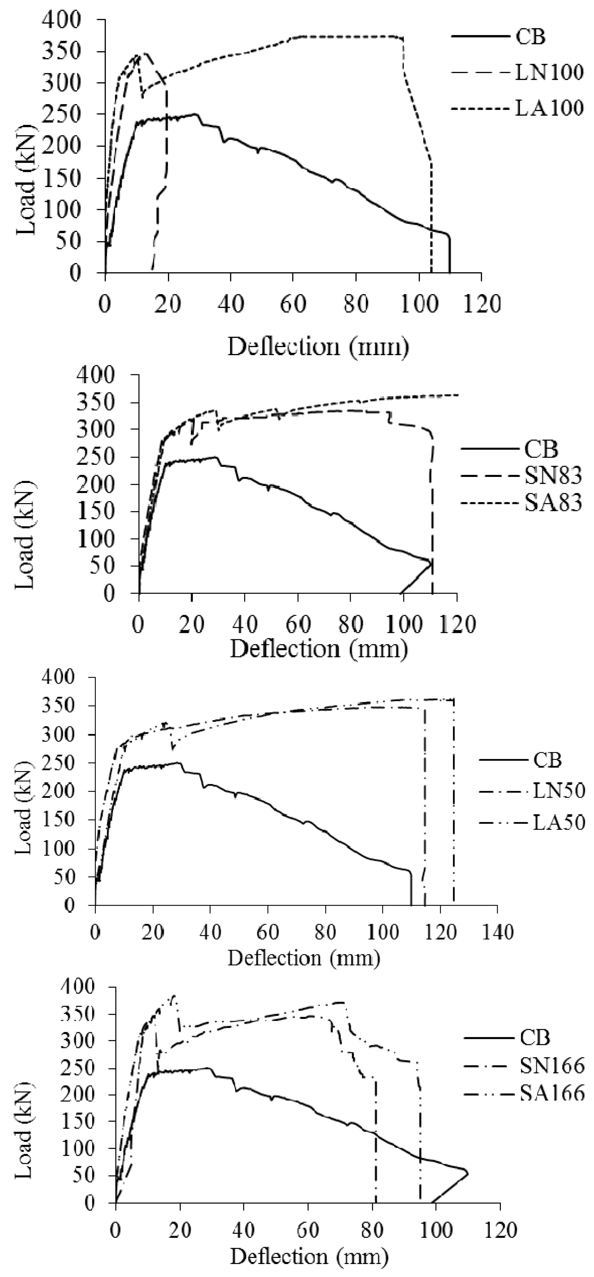
The load-midspan deflection curves for the test beams are presented in Figure 6. As can be observed, all beams with CFRP sheet/laminate, with or without the anchor, achieved higher load compared to the control beam. However, the important characteristic of the beams with anchors is the absence of a relatively steep drop in load after initiation of partial debonding and the ability of the beams with anchor to maintain their ductile response until the rupture of the FRP.
Note that the maximum deflection reached in the control beam before the commencement of the descending part of its load-deflection curve is approximately 35 mm while the FRP strengthened beams reached up to 80 mm deflection while maintaining their strength. The drop in load in the FRP strengthened beam indicates either the formation of a large crack or the initiation of slippage. It could be noticed that in each case the beam with anchor has smaller drop in load, higher strength and greater deflection at failure than its companion beam without anchor.
Figure 6. Comparison of load deflection behavior of test beams.
Technologies 03 00238 g006

5.2. Ultimate Flexural Strength

The theoretical or nominal flexural capacity, Mn, of each beam was calculated based on the Canadian Standard CSA 23.3-04 (CSA 2004) [35] and is shown in Table 3. The calculated strength is based on the assumption of strain compatibility, i.e., the FRP laminate is assumed fully bonded until failure, and the concrete ultimate compressive strain is assumed equal to 0.0035.
The experimentally measured failure moments of the test beams, denoted as MF, are presented in column 4 of Table 3. The control beam CB failed at 4% higher load than its theoretical strength value. This beam failed in a flexural-shear mode, i.e., high shear stresses contributed to its failure. Beam LN100 debonded at 260 kN.m, and the test was stopped immediately after. The theoretical ultimate moment capacity of this beam based on full bond is 270 kN.m. Beam LA100, which is the companion to LN100, failed at 3.5% higher load than its theoretical value. Hence, in comparison to LN100, which had no anchors, LA100 with anchors, achieved 7.5% higher moment. Similarly, Beam SN166 achieved 93% of its theoretical capacity while Beam SA166 reached 14.4% higher load compared to Beam SN166. It is clear that the higher capacity of SA166 is due to the anchors because the two beams were otherwise nominally identical. Comparing Beams LN50 and LA50, they failed at 11% and 16% higher load, respectively, than their corresponding theoretical values, and the beam with anchor had approximately 5% higher strength than the one without anchor. Finally, Beams SN83 and SA83 achieved failure moments 8.1% and 17.6% higher than their respective theoretical values. In this case, the beam with anchors achieved 9.5% higher moment than the one without anchor. Based on this discussion, in each case, the anchors allowed the beams to achieve higher strength. In the case of the beams with the larger amount of FRP, the actual failure load in all cases exceeded the corresponding theoretical value. This means that the anchors allowed the beams to reach their maximum theoretical capacity.
Table 3. Theoretical and measured failure moments and measured debonding moment of test beams.
BeamTheoretical Failure Moment, Mu (kN.m)Experimental M F M F control M F M u
Debonding Moment Mdb (kN.m)Failure Moment MF (kN.m)
CB180-187.91.001.04
LN100270260.1---
LA100257.0279.61.491.04
SN166263260.0244.71.300.93
SA166288.6279.91.491.06
LN50235223.9260.81.391.11
LA50240.9271.91.451.16
SN83232237.7250.81.331.08
SA83251.3272.91.451.18

5.3. Debonding Load

The debonding loads, Pdb, of the test beams are shown in column 2 of Table 4. In each case, comparison can be made between the debonding load of the beam without and with anchor. Comparing Beam LN100 and LA100, the anchor did not increase the debonding capacity of the beam. As for Beam SN166 and Beam SA166, the anchor increased the debonding load of the beam by 11%. Similarly, considering LN50 and LA50, the beam with anchor achieved 7.6% higher debonding load. Finally, comparing Beams SN83 and SA83, one observes that the beam with anchor debonded at 5.7% higher load. Based on the preceding loads, it can be stated that in general the anchors were able to delay debonding.
Table 4. Debonding load, drop in load after debonding and the failure load for the test beams.
BeamPdb (kN)Pdrop (kN)PF (kN)ΔPdrop (kN)ΔPdrop/Pdb (%)PF/Pdb (%)
CB--250.5---
LN100346.8293.8-53.015.3-
LA100342.6276.3372.866.319.4108.8
SN166346.8245.5326.2101.329.2 94.1
SA166384.8319.9373.164.916.9 97.0
LN50298.5262.6347.735.912.0116.5
LA50321.2274.0362.547.214.7112.9
SN83316.9273.4334.443.513.7105.5
SA831335.1298.5363.836.610.9108.6

5.4. Load Drop after Debonding

The drop in load after debonding signifies the loss in the flexural strength and stiffness of the beam caused by debonding. The magnitude of this drop is indicative of the extent of debonding and of the relative contribution of the external FRP to the flexural strength and stiffness of the beam, following debonding initiation. The magnitude of this drop, ΔPdrop, for all the beams is shown in column 5 of Table 4.
Comparing Beam LN100 and LA100, as remarked earlier, in the case of Beam LA100, the anchors did not contribute either to a higher debonding load or to a greater stiffness. It is believed that there might have been some flaw in the manner in which the laminate was bonded to this beam. As for Beam SN166 and SA166, due to the anchors, as column 6 of Table 4 indicates, the drop in load relative to the debonding load, for these beams was 29.2% and 16.9%, respectively, which indicates that the extent of debonding in the beam with anchors was smaller. In other words, the debonding might have been over a smaller length of the FRP-concrete interface.
In Table 4, Pdb is the maximum load before debonding, Pdrop is the load immediately after debonding, and ΔPdrop = Pdb − Pdrop. Beam LN50 compared to LA50 debonded at 7.6% higher load. If we look at the load drop for the two beams (column 5 of Table 4), it is 35.9 kN and 47.2 kN, respectively. Hence, in this case, the beam with anchors debonded over a slightly higher length, and the anchors were not able to prevent the propagation of debonding. Finally, comparing Beam SN83 and SA83, one can observe that the anchors in Beam SA83 delayed debonding and increased the debonding load by 5.7%. It can be stated that generally the anchors delayed debonding and increased the debonding load, but they did not substantially limit the propagation of the debonding zone along the concrete-FRP interface.
Comparing the failure load of each beam to its debonding load (see column 7 of Table 4), the beams with the larger amount of FRP sheet reinforcement had lower failure loads than their debonding loads, irrespective of the presence of anchors. This behavior is unexpected because the width of the interface between the FRP and the concrete in the beams reinforced with FRP sheet was greater than in the corresponding beams reinforced with the laminate. Beam LA100 reinforced with the laminate had a failure load 8.8% higher than its debonding load. In the beams with smaller amount of FRP sheet or laminate, the failure load was always higher than the debonding load, irrespective of the presence of anchors. This indicates that, in these beams, the debonding gradually spread from the centre of the beam towards the supports. Thus, the amount of external reinforcement has major influence on the debonding load and on the ultimate moment capacity of beams externally strengthened with FRP. Consequently, practically all FRP design standards expressions for maximum allowable strain in externally bonded FRP explicitly include this parameter besides the FRP elastic modulus.
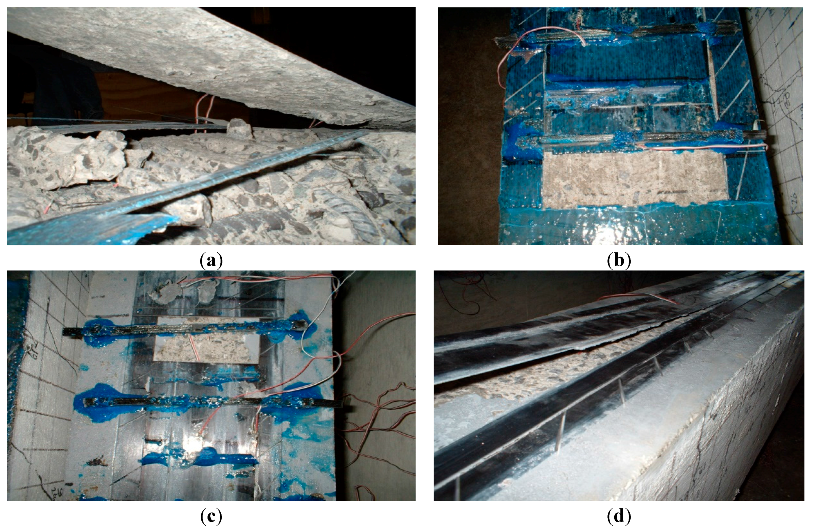
Figure 7 shows typical failure modes for the different beams with and without anchors. They show debonding in the case of beams without anchors and slippage in the case of beams with anchors. Anchors prevented full debonding and contributed to the beam overall flexural strength.
Figure 7. Typical failure for beams with and without anchors. (a) Debonding in Beam SN166; (b) Sheet end slippage in Beam SA166; (c) Slippage happened in Beam LA100; (d) Debonding in Beam LN100.
Technologies 03 00238 g007

5.5. Strain Profile

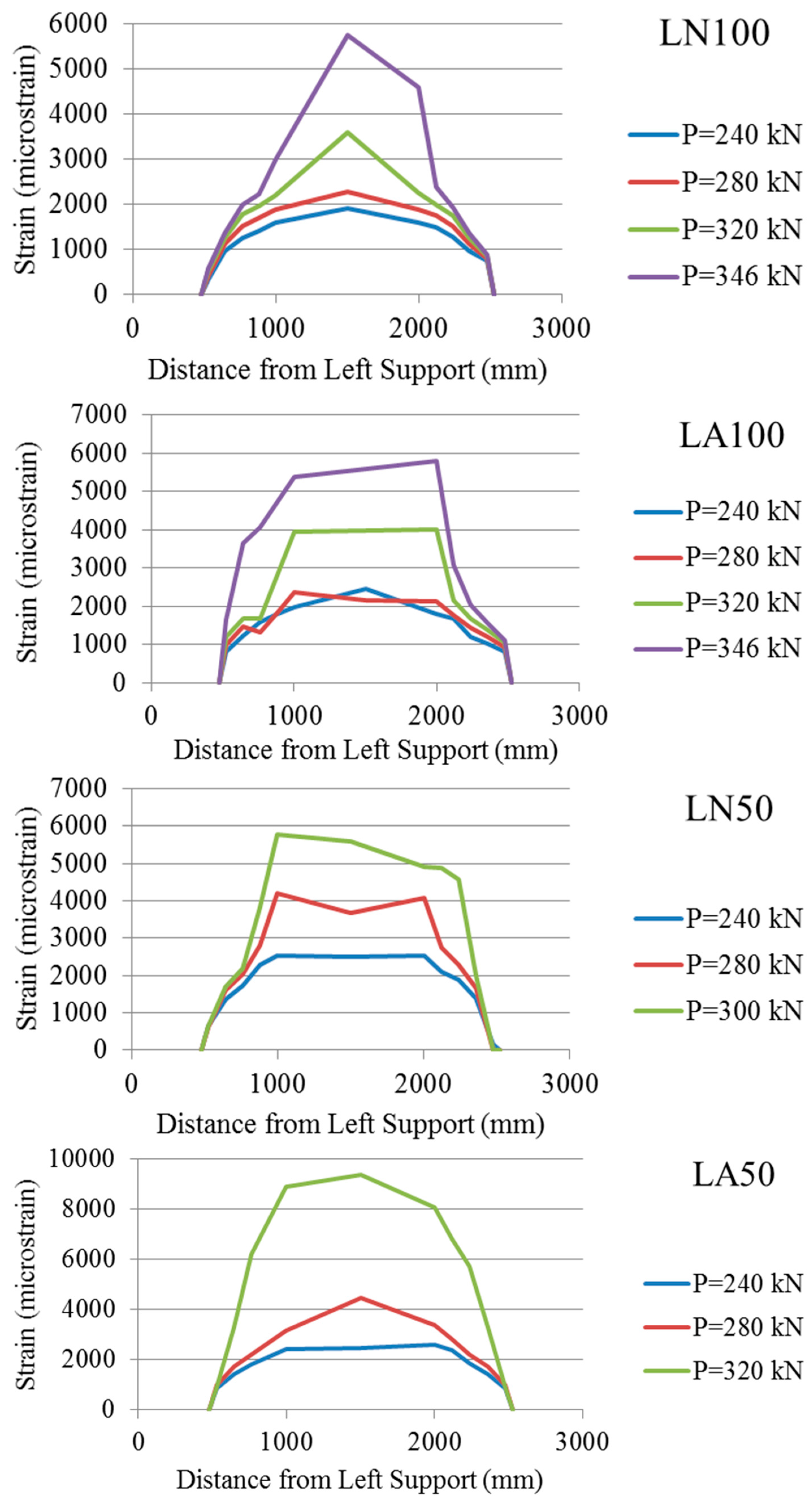
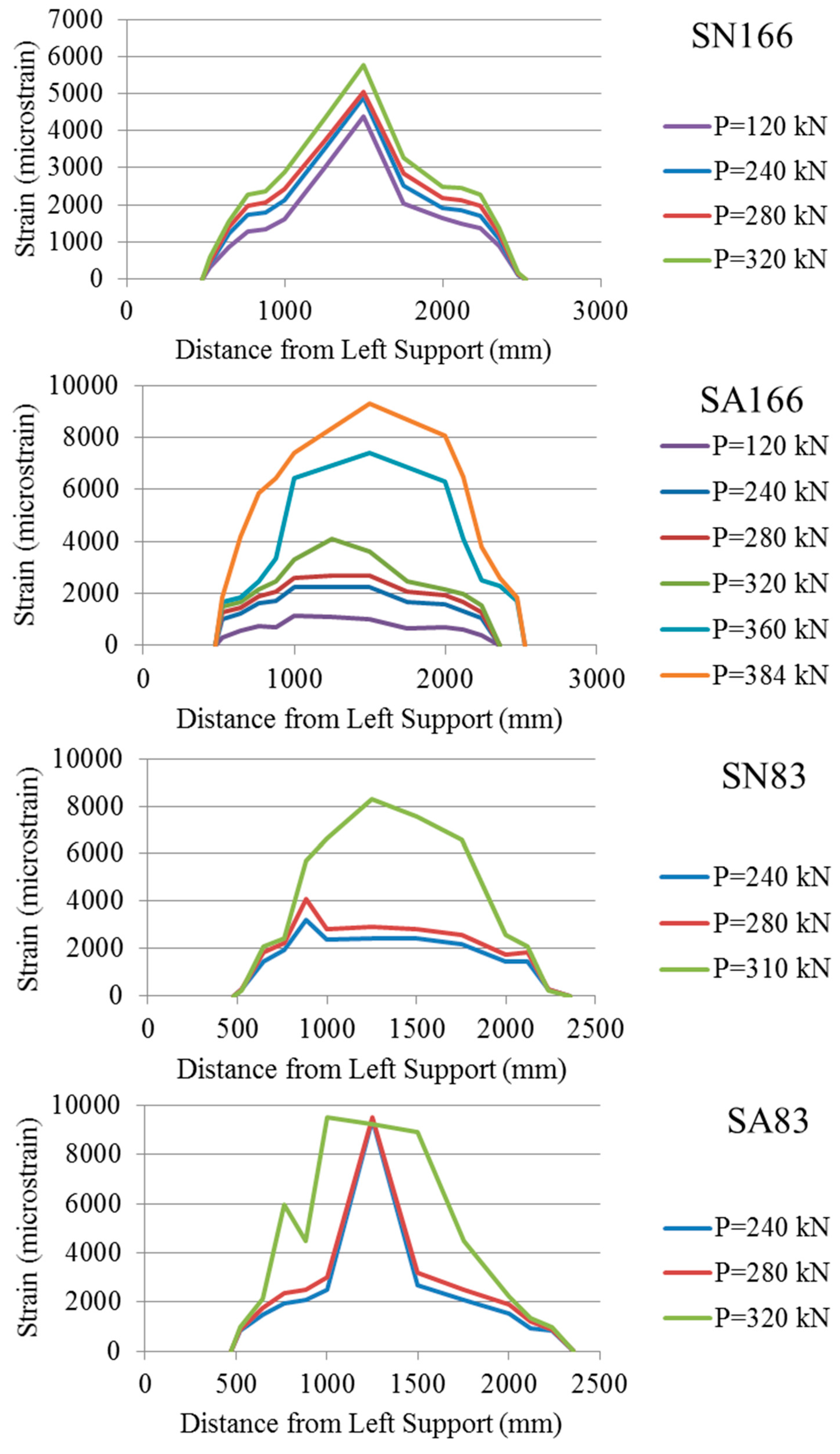
Strain profile along the laminate/sheet was recorded. Figure 8 and Figure 9 show the strain variation at the same load levels for the test beams with and without anchors. Beam LN100 shows a strain profile similar in shape to the bending moment diagram while beam LA100 shows a more flat strain profile with constant strain region, indicating slippage in this region. Both beams achieved approximately equal strain at mid-span. The anchors allowed the laminate to achieve 62.7% increase in its maximum strain compared to its companion beam with no anchors, and it reached approximately 49% of the laminate rupture strain. Beam SN166 achieved 5760 microstrain at 320 kN while its companion beam SA166 achieved 4000 micro strain at the same load level.
Figure 8. Strain variation along the FRP laminate in beams with and without anchors.
Technologies 03 00238 g008
Figure 9. Strain variation along the FRP sheet in beams with and without anchors.
Technologies 03 00238 g009
No data was recorded beyond this load for beam SN166 while the maximum strain in beam SA166 reached 9300 micro strain at maximum load of 384 kN. The maximum strain in Beam SA166 is 56% of the CFRP sheet rupture strain. Similarly, Beam SA83 achieved higher maximum strain compared to its companion beam without anchor.

5.6. Ductility and Energy Absorption

To be able to evaluate the effectiveness of the proposed anchorage system, the ductility and the energy absorption of the strengthened beams were evaluated. The ductility index, μ, may be calculated as the deflection at failure divided by the deflection at the maximum load, Pmax, achieved just before debonding. In the case of load-deflection curves with a descending portion after Pmax, it is defined as the deflection corresponding to 0.85 Pmax on the descending part of the curve, divided by the deflection corresponding to Pmax. Hence, in the case of the control beam, the failure load was taken as 0.85 of the maximum load reached. The area under the complete load- deflection curve represents the total energy absorbed by the beam up to failure. The energy absorption index, η, may be defined as the calculated area under the load deflection curve of the strengthened beam to the area under the load deflection curve of the control beam. All the strengthened beams with anchors show higher energy absorption compared to the ones without anchor, except beam LN100, which shows very low energy absorption. The latter is due to the fact that the test was stopped in the case of this beam, but, had loading been continued after debonding, the beam would have followed the load-deflection curve of the control beam.
Table 5 summarizes the maximum load at failure, deflection at debonding and at failure load, the ductility index and the energy absorption index. Column 2 and 3 in Table 5 show that the beams with anchor debonded at a higher deflection compared to their companion beams without anchor. Moreover, the deflection at failure load was always higher in the case of the beams with anchor compared to the beams without anchor. Due to the fact that the beams with anchors achieved somewhat higher deflection at failure, the ductility index, μ, does not reflect the actual ability of the anchors to increase ductility. On the other hand, the energy absorption index, η, is higher in the case of the beams with anchors compared to the beams without anchors. It is also important to mention that Beam SA83, which was retrofitted with a large number of anchors, had 37.8% higher energy absorption compared to its companion beam without anchor.
Table 5. Deflection, ductility and energy absorption of the test beams.
BeamMax. Load at Failure (kN)Deflection at Debonding Load (mm)Deflection at Failure Load (mm)Ductility Index (μ)Energy Absorbed (kN.m)Energy Absorption Index (η)
CB212.529.6 *37.61.277.81.00
LN100344.513.213.21.003.30.43
LA100371.010.593.28.8832.24.11
SN166342.012.265.65.3819.22.45
SA166368.518.971.33.7723.32.98
LN50338.19.2114.412.4336.44.65
LA50354.725.8124.44.8239.65.06
SN83328.120.194.84.7229.13.71
SA83361.329.8123.44.1440.05.11
* Deflection at maximum load.

5.7. Maximum Strain Attained in FRP versus Its Rupture and Allowable Strains

Table 6 shows the maximum recorded FRP strain, εF, in each beam and the corresponding allowable strain, ε F ACI , recommended by the American Concrete Institute (ACI) 440 [9] and CSA S806 [8] for the particular retrofit scheme. The quantity ε F ACI is calculated as
ε F ACI = 0.41 f c ' n E F t F
where fc, is the concrete strength (MPa), n is the number of FRP laminate plies or layers used, tF is the thickness of each ply (mm) and EF is the elastic modulus of the FRP (MPa). The table also shows the ratio of εF to the FRP rupture strain, εFu, and the ratio of εF to ε F ACI . The latter ratio has been referred to as the anchor efficiency factor by Kalfat et al. [13]. In fact, both ratios are indicator of the efficient utilization of the FRP strength in retrofit works. It can be observed that in none of the beams, the FRP reached its tensile rupture strain, but the beams with anchor achieved higher strain compared to their companion beams without anchor. Therefore, the anchors in these cases increased the maximum achievable strain in the FRP. According to Kalfat et al. [13], the highest average efficiency factor achieved by existing anchors is 1.87, and this was achieved by using steel plates and anchor bolts. It is important to observe that the ACI allowable FRP strain value for beams without anchor was not achieved in any of the current test beams. In the case of beams with anchor, except beam LA100, the anchor allowed the laminate/sheet to surpass its theoretical strain value based on the ACI equation. Therefore, using the anchor allows one to conservatively estimate the ultimate strength of CFRP strengthened beams based on the ACI 440 Committee recommendation for allowable FRP strain. Without the anchor, the ACI recommended alue may not be reached in some cases.
Table 6. Maximum recorded fiber reinforced polymers (FRP) strain in test beams compared to its rupture strain and to the maximum strain allowed by the American Concrete Institute (ACI) Committee 440 Guidelines (ACI 440.2R-08) [9].
Beam DesignationMaximum Strain Recorded in FRP, εF
(microstrain)
ε F ACI
(microstrain)
ε F ε Fu Efficiency Factor = ε F ε F ACI
LN100575066400.300.87
LA10057900.310.87
LN5057600.300.87
LA5093700.491.41
SN166576088200.350.65
SA16693000.561.05
SN8383200.500.94
SA8398200.591.08

6. Conclusions

The test results in this study showed:
(1)
Beams outfitted with the proposed C-anchor had generally 5%–10% higher debonding load and reached higher maximum load and corresponding deflection than the companion beams without anchor.
(2)
Beams with anchor reached higher strain in the FRP compared to their companion beams without anchor and the maximum strain exceeded the theoretical strain based on the ACI 440 equation.
(3)
Although complete separation of the laminate/sheet from the concrete was not observed in any of the beams with anchor, substantial slip was noticed at one end of the FRP laminate.
(4)
Despite the fact that some of the strengthened beams were over-reinforced, they failed in a ductile fashion because the failure was initiated by debonding and thereafter they reverted to their un-strengthened under-reinforced behavior.
(5)
The anchor was found to be effective in limiting the extent of debonding along the laminate, thus indirectly contributing to the beam flexural stiffness by limiting its crack width.
(6)
The anchor significantly increased the energy absorption or toughness of the strengthened beams, but further investigation is needed to optimize the number and location of the anchors.
(7)
The proposed C-anchor shows promise, but its performance can be improved by increasing its contact surface with the concrete and the FRP laminate. In other words, the anchor spine width needs to be much larger than its thickness in order to increase its surface area for resisting interfacial shear.

Acknowledgments

The authors gratefully acknowledge the financial assistance of the Natural Sciences and Engineering Research Council Canada in support of this study through the Discovery Grant to the first author.

Author Contributions

The research was designed by Ghani Razaqpur while it was performed by Ahmed B. Mostafa. The test data were jointly analyzed by both. The first author made greater contribution to the interpretation of the test results, while both authors contributed equally to the writing of the final manuscript. Both authors have read and approved the final manuscript.

Conflicts of Interest

The authors declare no conflict of interest.

References

  1. Teng, J.G.; Chen, J.F.; Smith, S.T.; Lam, L. FRP Strengthening RC Structures; John Wiley and Sons, Inc.: New York, NY, USA, 2002. [Google Scholar]
  2. Oehlers, D.J.; Seracino, R. Design of FRP and Steel Plated RC Structures; Elsevier: London, UK, 2004. [Google Scholar]
  3. Smith, S.T.; Teng, J.G. FRP strengthened RC beam. II assessment of debonding strength models. Eng. Struct. 2002, 24, 397–417. [Google Scholar] [CrossRef]
  4. Smith, S.T.; Teng, J.G. FRP-strengthened RC beams I: Review of debonding strength models. Eng. Struct. 2002, 24, 385–395. [Google Scholar] [CrossRef]
  5. Mostafa, A. Development of a New FRP Anchor for Externally Bonded CFRP Sheet/Laminate to Beams. Master’s Thesis, Carleton University, Ottawa, ON, Canada, 2005. [Google Scholar]
  6. Mostafa, A. A Novel FRP Anchor for Preventing Delamination in FRP Strengthened Concrete Beams. Ph.D. Thesis, McMaster University, Hamilton, ON, Canada, 2010. [Google Scholar]
  7. Mostafa, A.; Razaqpur, A.G. CFRP anchor for preventing premature debonding of externally bonded frp laminates from concrete. J. Compos. Constr. 2013, 17, 641–650. [Google Scholar] [CrossRef]
  8. CSA. Design and Construction of Building Components with Fiber-Reinforcement Polymers; CSA Standard S806–12; CSA: Rexdale (Toronto), ON, Canada, 2012. [Google Scholar]
  9. ACI Committee 440. 440.2R-08 Guide for the Design and Construction of Externally Bonded FRP Systems for Strengthening Concrete Structures; American Concrete Institute: Farmington Hills, MI, USA, 2008. [Google Scholar]
  10. Federation internationale du beton (fib). Design and Use of Externally Bonded Fiber Reinforced Polymer Reinforcement (FRP EBR) for Reinforced Concrete Structures; Technical Report, Bulletin No.14; International Federation for Structural Concrete (fib): Lausanne, Switzerland, 2011. [Google Scholar]
  11. Wu, Y.F.; Yan, J.H.; Zhou, Y.W.; Xia, Y. Ultimate strength of reinforced concrete beams retrofitted with hybrid bonded fiber-reinforced polymer. ACI Struct. J. 2010, 107, 451–460. [Google Scholar]
  12. Oller, E.; Salcedo, D.C.; Mari, A. Flexural strengthening of reinforced concrete beams with externally bonded CFRP laminates. In Proceedings of Conference on Composites in Construction, Porto, Portugal, 10–12 October 2001; Balkema Publishers; pp. 473–478.
  13. Kalfat, R.; Al-Mahaidi, R.; Smith, S.T. Anchorage devices used to improve the performance of reinforced concrete beams retrofitted with frp composites: A-state-of-the-art review. J. Compos. Constr. 2013, 17, 14–33. [Google Scholar] [CrossRef]
  14. Spadea, G.; Bencardino, F.; Swamy, R.N. Structural behavior of composite RC beams with externally bonded CFRP. J. Compos. Constr. 1998, 2, 132–137. [Google Scholar] [CrossRef]
  15. Lamanna, A.J.; Bank, L.C.; Scott, D.W. Flexural strengthening of RC beams using fasteners and FRP strips. ACI Struct. J. 2001, 93, 368–376. [Google Scholar]
  16. Martin, J.; Lamanna, A. Performance of mechanically fastened FRP strengthened concrete beams in flexure. J. Compos. Constr. 2008, 12, 257–265. [Google Scholar] [CrossRef]
  17. Elsayed, W.; Ebead, U.; Neale, K. Studies on mechanically fastened fiber-reinforced polymer strengthening systems. ACI Struct. J. 2009, 106, 49–59. [Google Scholar]
  18. Teng, J.G.; Lam, L. Strengthen of RC cantilever slabs bonded with gfrp strips. J. Compos. Constr. 2001, 5, 221–227. [Google Scholar]
  19. Smith, S.T.; Kim, S.J. Shear Strength and Behavior of FRP Spike Anchors in FRP-to-Concrete Joint Assemblies, Proceedings of the 5th International Conference on Advanced Composite Materials in Bridges and Structures 2008 (ACMBS-V 2008), Winnipeg, MB, Canada, 22–24 July 2008; Canadian Society for Civil Engineering: Montreal, QC, Canada, 2008.
  20. Ceroni, F.; Pecce, M.; Matthys, S.; Taerwe, L. Debonding strength and anchorage devices for reinforced concrete elements strengthened with frp sheet. Compos. Part B Eng. 2008, 39, 429–441. [Google Scholar] [CrossRef]
  21. Orton, S.L.; Jirsa, J.O.; Bayrak, O. Design consideration of carbon fiber anchors. J. Compos. Constr. 2008, 12, 608–616. [Google Scholar] [CrossRef]
  22. Smith, S.T. FRP Anchors: Recent Advances in Research and Understanding, Proceedings of the 2nd International Conference on FRP in Structures—APFIS 2009, Seoul, Korea, 9–11 December 2009.
  23. Pham, L.; Jirsa, J.O.; Bayrak, O. Development of quality control tests for CFRP anchors. In Proceedings of the 9th International Symposium of the Fiber-Reinforced Polymer Reinforcement for Reinforced Concrete Structures (FRPRCS-9), Sydney, Australia, 13–15 July 2009.
  24. Micelli, F.; Rizzo, A.; Galati, D. Anchorage of composite laminates in rc flexural beams. Struct. Concr. 2010, 11, 117–126. [Google Scholar]
  25. Smith, S.T.; Teng, J.G. Shear-bending interaction in debonding failures of FRP-plated RC beams. Adv. Struct. Eng. 2003, 6, 183–199. [Google Scholar] [CrossRef]
  26. Pham, H.B.; Al-Mahaidi, R. Prediction models for debonding failure loads of carbon fiber reinforced polymer retrofitted reinforced concrete beams. J. Compos. Constr. 2006, 10, 48–59. [Google Scholar] [CrossRef]
  27. Razaqpur, A.G.; Mostafa, A. A new CFRP anchor for preventing separation of externally bonded laminates from concrete. In Proceedings of the 4th International Conference on the on Construction Materials, Nagoya, Japan, 24–26 August 2009.
  28. Swamy, R.N.; Jones, R.; Bloxham, J.W. Structural behavior of reinforced concrete beams strengthened by epoxy-bonded steel plates. Struct. Eng. 1987, 65, 59–68. [Google Scholar]
  29. Takahashi, Y.; Sato, Y.; Ueda, T.; Maaeda, T.; Kobayashi, A. Flexural Behavior of RC Beams with Externally Bonded Carbon Fiber Sheet, Proceedings of the 3rd International Symposium on non-Metallic (FRP) Reinforcement for Concrete Structures (FRPRCS-3), Sapporo, Japan, 14–16 October 1997; Japan Concrete Institute: Tokyo, Japan, 1997; Volume 1, pp. 327–334.
  30. Poulsen, E.; Bendtsen, L.; Mortensen, J.; Ottosen, N.S. Anchorage and Laps of CFRP Strips for the Strengthening of RC Structural Components, Proceedings of Composite in Construction, Porto, Portugal, 10–12 October 2001; Balkema Publishers: Leiden, The Netherlands, 2001; pp. 205–209.
  31. Meier, U. Strengthening of structures using carbon fiber/epoxy composites. Constr. Build. Mater. 1995, 9, 341–351. [Google Scholar] [CrossRef]
  32. SIKA Carbodur. Engineering Guidelines for the use of Sika CarboDur (CFRP) Laminate for Structural Strengthening of Concrete Structures; Sika Corporation: Lyndhurst, NJ, USA, 1997. [Google Scholar]
  33. Ali, A.; Abdalla, J.; Hawileh, R.; Gala, K. CFRP mechanical anchorage for externally strengthened RC beams under flexural. Phys. Procedia 2014, 55, 10–16. [Google Scholar] [CrossRef]
  34. Zaghloul, A. Behavior and Strength of CFRP Reinforced Flat Plate Interior Column Connections Subjected to Shear and Unbalanced Moments. Master’s Thesis, Carleton University, Ottawa, ON, Canada, 2002. [Google Scholar]
  35. Cement Association of Canada. Concrete Design Handbook, 3rd ed.; Cement Association of Canada: Ottawa, ON, Canada, 2005.