Article

Improved Technology with Backfilling in Potash Mines

by
Denis A. Stadnik
1,*,
Nino M. Stadnik
2,
Alexey G. Zhilin
2,
Ruslan G. Kisnichian
2 and
Eduard E. Permyakov
2
1
Mining Department, Sergo Ordzhonikidze Russian State University for Geological Prospecting, Moscow 117485, Russia
2
Mining Department, North Caucasian Institute of Mining and Metallurgy (State Technological University), Vladikavkaz 362021, Russia
*
Author to whom correspondence should be addressed.
Technologies 2026, 14(8), 505; https://doi.org/10.3390/technologies14080505
Submission received: 5 July 2026 / Revised: 30 July 2026 / Accepted: 4 August 2026 / Published: 12 August 2026
(This article belongs to the Section Construction Technologies)

Abstract

The development of potash deposits is generally accompanied by large losses of minerals in the subsurface. The main reason for these losses is the use of a room-and-pillar mining system, where left pillars hold the overlying rock strata and aquifers located above the productive seams. Over time, the bearing elements of the mining system begin to deteriorate, leading to a loss of continuity of the water-protective stratum, the formation of water-conducting fractures, salt dissolution, and consequently, the flooding of the potash mine. The most effective method for solving production problems in the field of increasing mineral recovery and mine safety is the introduction of backfilling technology. The aim of the study is to identify the effect of backfilling on the stress–strain state of the rock mass in the vicinity of stopping and backfilling operations, to develop a technology for potash ore extraction with increased recovery, and also to solve the fundamental issue of the proposed technology, namely, the transport and property considerations of the backfill mixture. Numerical modeling methods and analytical derivations of calculation formulas for backfill mixture transport are used in the work. A comparison of dry, hydraulic, and hardening backfill mixtures is carried out. The study established that hardening backfill ensures a faster transition to the stage of mining the remaining reserves. A technology for pillar extraction with the leaving of technologically necessary narrow pillars is proposed, allowing for the safety of mining operations. Formulas are derived for calculating the required strength of the backfill based on the loading degree of the technological pillar. Transportability criteria are formulated, and a calculation procedure for pipeline transport parameters under gravity and gravity-pneumatic modes is developed. The proposed technology for potash ore extraction with hardening backfill allows for increased mineral recovery while maintaining safe conditions for undermining the water-protective stratum.

1. Introduction

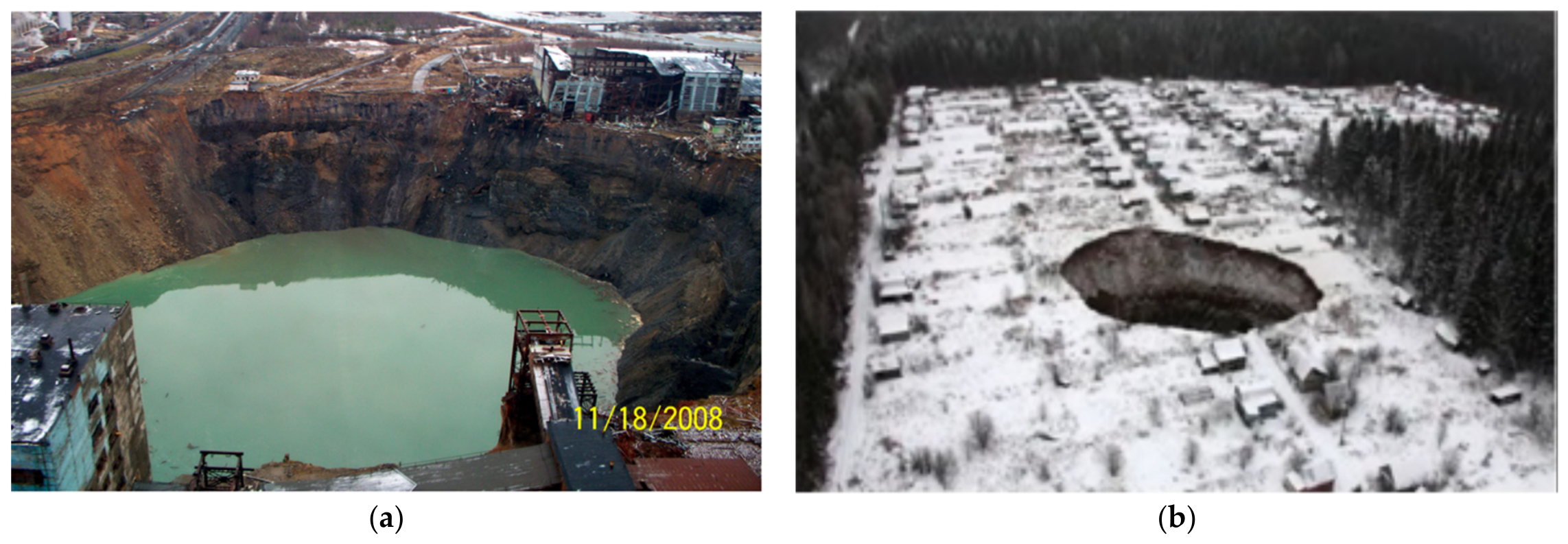
The specific nature of potash deposit extraction is associated with the high solubility of the mined salts and the presence of overlying aquifers. The renowned Canadian mining engineer Prugger noted in his work [1]: “It is probably true that more potash mines have been lost due to flooding than are currently in operation.” Unfortunately, emergency situations have not disappeared to this day, and most of them are associated with the destruction of the bearing elements of the applied mining system (Figure 1) [2,3,4].
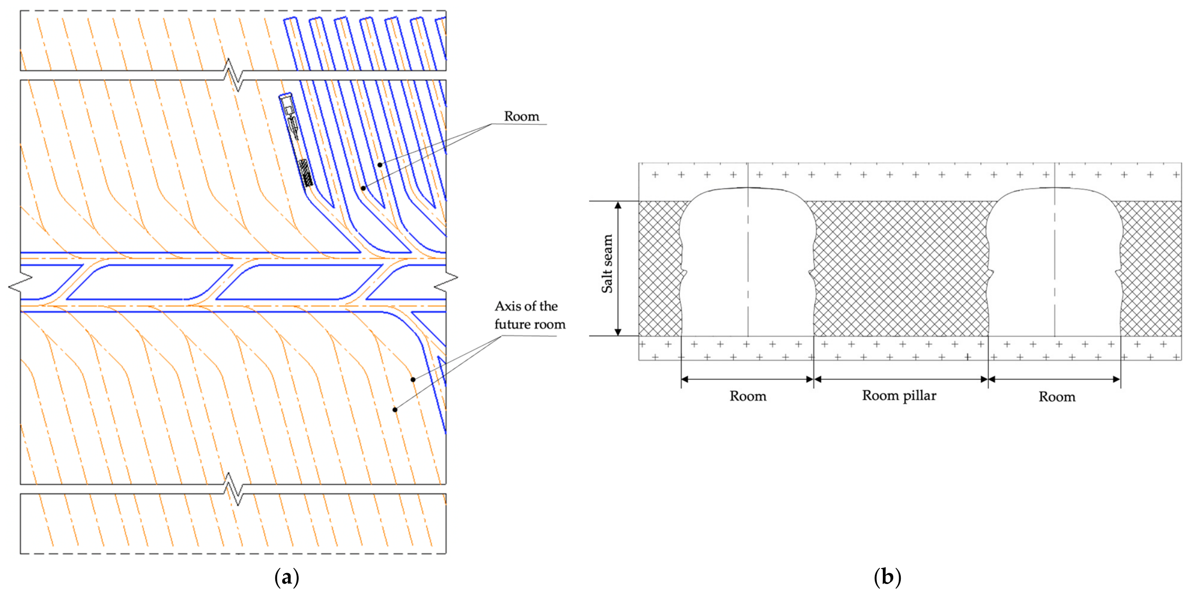
The vast majority of potash deposits use a room-and-pillar mining system, where long room pillars are left between the mined rooms. This method has a significant drawback—large losses of minerals left in the pillars. In mining practice, it is used only in cases of extreme necessity when other methods are impossible. For example, the most productive method in terms of extraction ratio is longwall mining [5,6]. However, the application of this method is limited, as its implementation requires a thick water-protective stratum and specific geology that would allow significant deflections without continuity loss. Another method involves cutting the room pillars [7,8]. This method increases extraction but significantly reduces rock mass stability, especially when mining adjacent seams. Therefore, this article considers the classic room-and-pillar mining system, which is the most widely applied in potash deposits (Figure 2).
The primary goal when choosing a mining method for potash mines is preserving the continuity of the water-protective stratum [10,11,12]. Otherwise, subvertical fractures occur, leading to water inrush from overlying aquifers and ultimately to mine flooding and, in most cases, to the complete loss of the entire deposit’s reserves. To ensure the safety of salt mines, new design documentation for deposit development has begun to include requirements for mandatory backfilling operations [13]. There are studies proving an increase in the bearing capacity of room pillars when using backfill [14,15,16]. However, in such a case, the stress distribution in the pillars, and in the rock mass generally, will differ from the case without backfilling operations.
New design documentation and research work currently do not account for the influence of backfilling on the stress–strain state of the mass, despite the fact that not only mine safety depends on this, but it also offers prospects for increasing potash ore extraction. In this regard, it is necessary to define the role of backfill masses in potash deposit development, as they can be aimed not only at increasing pillar stability but also become a structural element of the mining system.
The novelty of this research lies in three key aspects. First, the geomechanical aspect: a comprehensive quantitative assessment of the effect of different backfill types (dry, hydraulic, and hardening) on the long-term stress–strain state of room pillars and surface subsidence. The article presents a coupled numerical analysis of the interaction between different backfill types and room pillars. The model uses a realistic creep law calibrated for salt rocks and quantifies the time-dependent unloading of pillars. Second, the technological aspect: the proposition of a new technology for secondary extraction of room pillars with the leave of technological pillars to ensure safety. The article proposes a practical technology for secondary extraction of room pillars supported by an analytical formula for the required backfill strength. Third, the engineering aspect: the development of fundamental criteria and a first-principles calculation procedure for the gravity and gravity-pneumatic transport of hardening backfill, specifically tailored for potash mining conditions. The article introduces new transportability criteria (plasticity index and viscosity index) for hardening backfill and an engineering calculation procedure for gravity and gravity-pneumatic pipeline transport, which, although requiring experimental verification, provides a systematic basis for design.
The aim of this study is to identify the effect of backfill on room pillars in a room-and-pillar mining system, assess the possibility of increasing mineral extraction through backfilling, and justify the features of mining operations during potash seam development.

2. Materials and Methods

Potash salts and host rocks exhibit creep even under relatively low loads. Traditional analytical calculation methods are often unable to correctly describe the dynamics of stress redistribution over time, especially during multi-stage extraction and subsequent backfilling of rooms. Numerical modeling methods are widely used to solve geomechanical problems related to assessing the stress–strain state of rock mass during underground mining [17,18,19,20]. Among the available software packages, FLAC (Version 8.00) holds a special place [21]. The choice of this software is due to the fundamental features that distinguish it from programs based on rheological modules, making it the most adequate tool for modeling plastic flow, creep, and large deformation processes in salt rocks, which exhibit pronounced rheological properties.
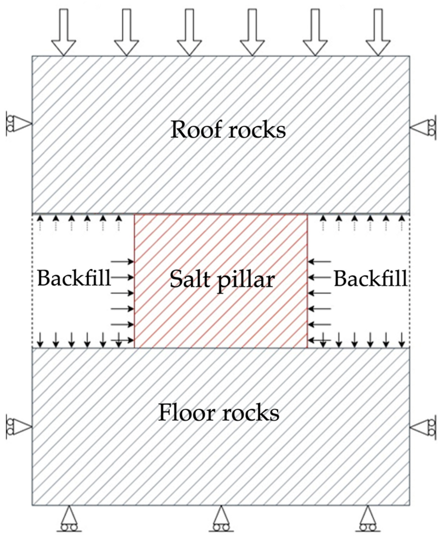
This work models a flat fragment of a room-and-pillar system with a conventionally infinite alternation of pillars and rooms. The model includes a room pillar, half the width of adjacent rooms, and the roof and floor rocks (Figure 3). The plane-strain assumption adopted in this work is a simplification aimed at investigating the fundamental mechanisms of interaction between the backfill mass and the pillars in the cross-section of the workings. This is a standard approach for the preliminary assessment of the stress–strain state of the rock mass when mining with long workings, where end-effects can be neglected over a significant portion of the face front. Similar modeling scenarios have been presented in [22,23,24,25,26].
Room backfilling is modeled as the reaction (confining pressure) of the backfill mass with specified compressive properties and room fill rate. Horizontal displacements are prohibited on the lateral boundaries of the model, and vertical displacements are prohibited on the lower boundary. A load from the weight of the overlying rocks is applied to the upper boundary. The initial stress state of the mass is assumed to be hydrostatic.
The rocks are represented as an isotropic, continuous, combined viscoelastic-plastic medium, where the Coulomb–Mohr criterion is used as the condition for the rock’s transition to a plastic state, and Norton’s power law is used to describe the rheological creep process. The averaged values of the strength and deformation properties of the rocks [27,28,29,30] and the parameters of the mining system adopted for modeling are given in Table 1 and Table 2, respectively.
As is known, Norton’s power law relates the strain rate to the magnitude of the acting stresses in the steady-state creep regime and is described by the dependence:
ε ˙ = A σ 1 σ 3 n
where ε ˙ is the material deformation rate; σ 1 and σ 3 are the principal maximum and minimum stresses; and A and n are creep parameters determined experimentally.
Calibration of the model considering actual data on earth surface subsidence at one of the Russian potash deposits and analysis of research results [31,32,33,34,35] allowed us to establish the following generalized values of creep parameters for salt rocks: n = 4.54; A = 5.33 × 10 35 Pa−n∙year−1.
The effect of the backfill mass is modeled through the reaction (confining pressure) it creates on the walls of the room pillar, the floor, and the roof. The backfill reaction is activated in the model only when the room roof subsides onto the backfill mass. The time of this event depends on the deformation rate of the modeled system and the backfill rate, and is calculated by a written FISH procedure.
The pressure of the backfill mass on the room floor is determined by its weight. From the moment the roof contacts the backfill, the corresponding surcharge from the overlying rocks is added to the pressure from the backfill’s own weight.
The reactive pressure of the backfill mass on the lateral walls of the room pillar depends on the magnitude of its volumetric compression caused by the lateral expansion of the pillar and is described by a generalized dependence obtained from the results of compression tests of backfill masses made from salt waste:
σ = n ln ε 0 ε 0 ε
where σ is the confining pressure (reaction) of the backfill mass on the pillar walls; ε is the volumetric deformation of the backfill mass; and n and ε 0 are compression parameters established experimentally.
As the room pillars are crushed by rock pressure (longitudinal deformations) and extruded into the backfilled goaf (transverse deformations), the backfill mass provides increasing resistance to their walls, increasing according to a logarithmic dependence. When volumetric deformations reach values equal to or greater than ε 0 , the transverse expansion of the pillar is prohibited in the model.
Mining enterprises usually use local production wastes and rocks from roadway drivings for backfilling operations [36]. The most obvious material for the potash industry is potash ore processing waste. According to studies [16,21,30,37,38], the average compression parameters for a hydraulic backfill mass from salt waste can be taken as n = 9.8 MPa, ε 0 = 0.178, and for a loose backfill mass from waste rock (halite)— n = 7.3 MPa, ε 0 = 0.35.
Dry backfill is mainly used in potash deposits. However, this type of backfill material has high shrinkage and caking, which means the bearing capacity of the pillars practically does not change. Nevertheless, the effect of dry backfill cannot be completely excluded. Some enterprises allow the use of hydraulic backfill, which consists of salt waste mixed with a saturated salt solution. Hydraulic backfill has higher strength compared to dry backfill. However, the main disadvantage is the need to build additional pumping stations and pump out brines. The effect of saturated brines on pillars is not fully understood. Brines are also a problem when developing seams with weak carnallite in the floor and sides of the workings [39,40,41,42,43]. This limits the applicability of hydraulic backfill, which further highlights the advantages of the hardening mixture. In this regard, there is a real need to create a hardening backfill that would be acceptable for use in salt mines, possess high strength and low shrinkage, and also create an economic effect, since the purchase of new materials can account for more than 80% of the total cost of backfilling operations [44].
Scientists in the fields of materials science, chemistry, and related sciences develop special materials and additives that improve the properties of backfill. From a technological point of view, the most important and complex aspect is the transportation of the backfill material through the entire mine system. Transporting hardening backfill is a more complex process compared to dry backfill. However, hardening backfill is multicomponent. Mixing various components makes it possible to control the physical and mechanical properties of the mixture and select available materials.

3. Results

3.1. Assessment of the Stress–Strain State of the Rock Mass

Due to the fact that salt rocks have pronounced rheological properties (creep), they deform but do not lose their continuity when placed under load. Excavation of previously mined potash seams has shown that room cavities eventually collapse and form a single medium [45,46]. Thus, as the roof rocks subside onto the backfill mass, processes of densification occur in the pillars.
When developing potash deposits, the parameters of the technology must be justified considering the time period between extraction stages. The state of the mass, specifically the stress state of the room pillars, depends on the degree of room backfilling, the mechanical properties of the backfill mass, and the time period between extraction stages.
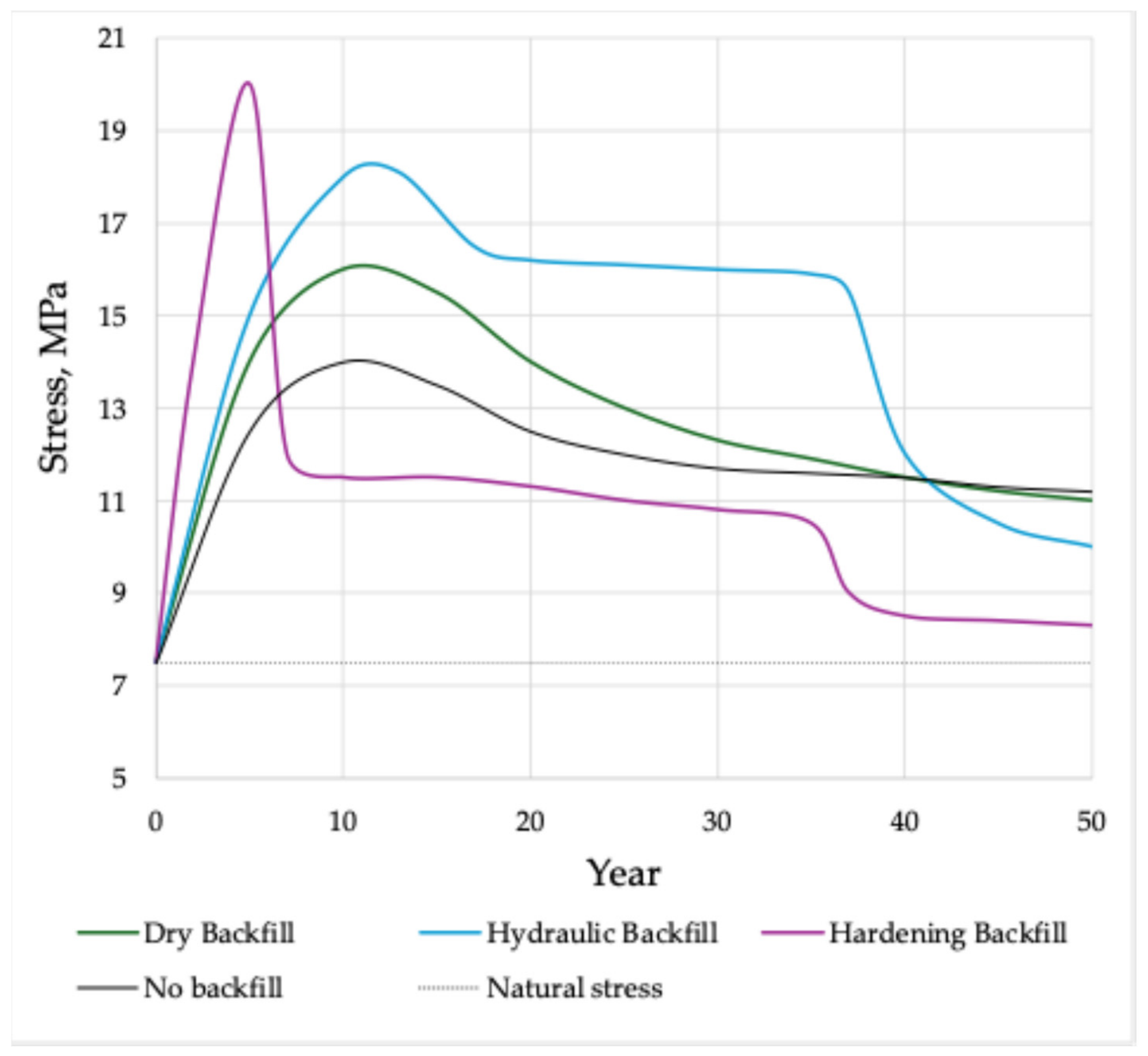
The article analyzes the influence of three types of backfill: dry, hydraulic, and hardening (Figure 4). When carrying out backfilling operations, due to the strengthening effect of the backfill mass, the stresses in the pillars reach higher values than in the variant without backfilling. However, in the years following extraction, a significant unloading of the room pillars from stresses occurs. The period of roof subsidence onto the backfill mass coincides with the period of unloading of the room pillars. The unloading period can be estimated from Figure 4. When using dry backfill, the stresses in the room pillars remain high throughout the entire modeling period (over 50 years). When using hydraulic backfill, pillar unloading begins 12 years after the start of extraction, and for hardening backfill, this period is estimated at 5 years. It should also be noted that hardening backfill not only starts to act faster but also reduces stresses in the room pillars more strongly compared to other types of backfill.
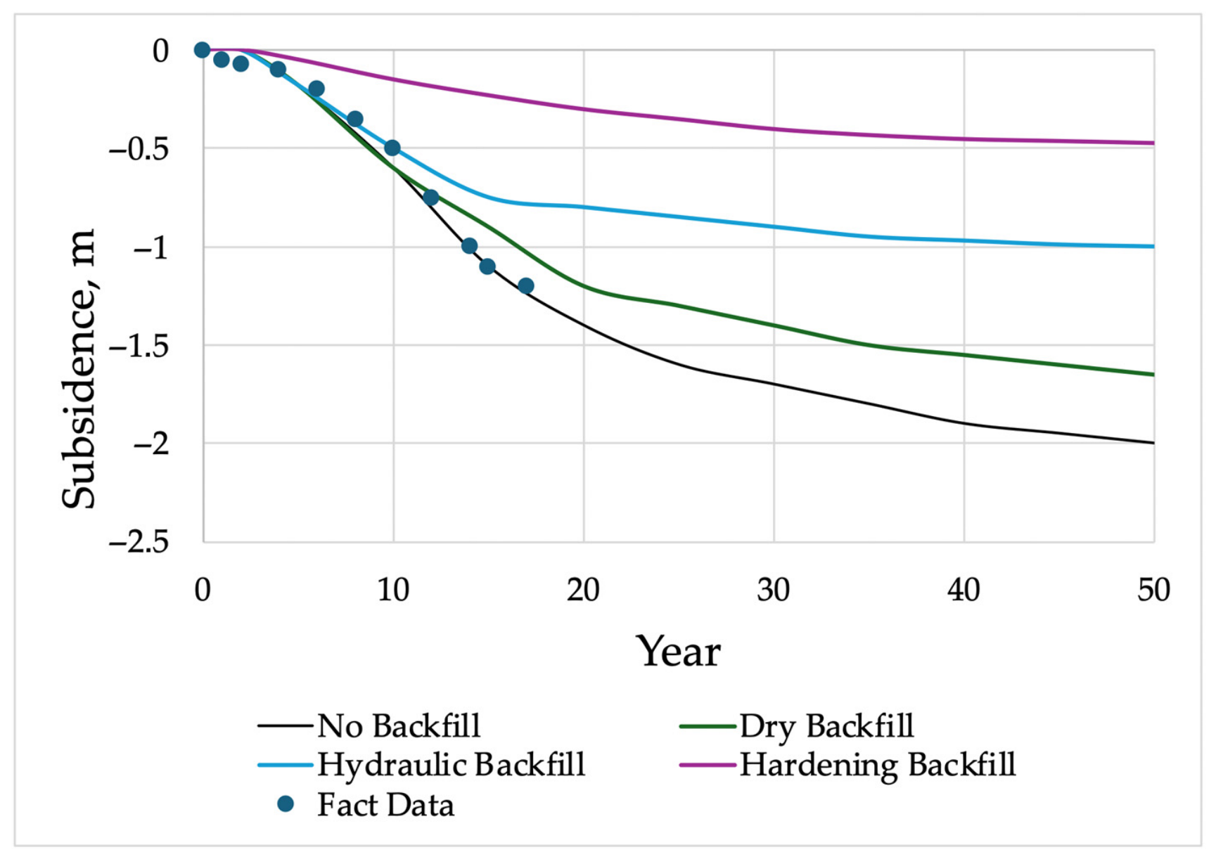
Figure 5 shows graphs of the increase in earth surface displacements obtained from modeling results for 50 years after the start of extraction. The graph also shows data on actual displacement parameters (fact data) at specific sections of the studied deposit, the conditions of which correspond to the modeling conditions without backfill.
The results show that dry backfill does have an effect on subsidence, although not a large one. Hardening backfill, as expected, showed the best results, i.e., minimal subsidence. Based on the above, it follows that to ensure mine safety from flooding, the use of hardening backfill is necessary when applying the room-and-pillar mining system.

3.2. Idea of a New Technology

In the context of increasing potash recovery and subsequent extraction of the room pillar, the safest conditions for secondary mining the seam occur when the backfill interacts with the mass, i.e., when the backfill begins to create reaction pressure.
According to the modeling results, hardening backfill allows for faster unloading of the pillar from high stresses, thereby making it possible to begin operations for its extraction.
The most obvious method seems to be extracting the supporting pillar adjacent to the backfill mass. However, the presence of unfilled voids in the rooms, insufficient knowledge of the subsidence behavior of the overlying rocks, and the fact that studies on reserve re-extraction [47,48] indicate collapses and the presence of delamination in the previously undermined mass suggest the need for additional safety measures when extracting room pillars.
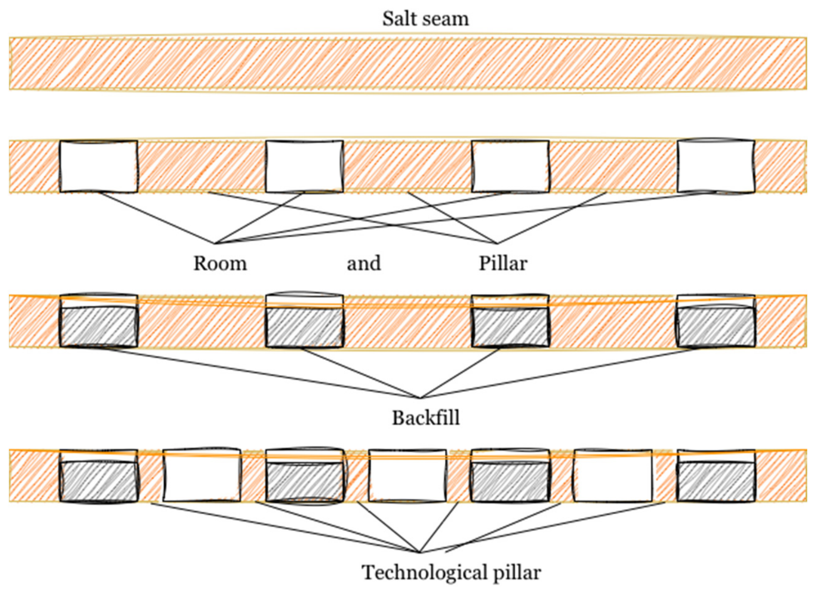
This article proposes a technology for extracting room pillars while leaving technologically necessary pillars (Figure 6).
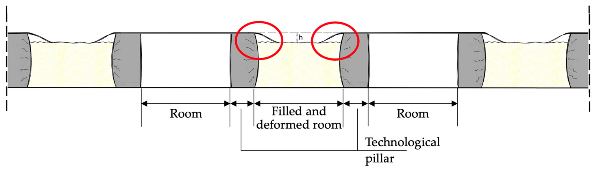
It is obvious that the technologically necessary pillars will not be intended for long-term load-bearing. However, they will prevent dangerous situations that can occur when extracting pillars adjacent to the backfill mass. The most unfavorable case is dynamic roof falls when extracting a pillar adjacent to the backfill mass (Figure 7). The technologically necessary pillars cannot serve as a long-term rigid structure for roof support. Nevertheless, this solution mitigates the problem of non-uniform subsidence of the roof and overlying rocks above the mined seam.
The sufficient width of pillars in potash deposits is determined by the degree of loading, which expresses the ratio of the applied load to their bearing capacity and is determined by the formula:
C = Q P
where Q is the specific load on the pillar, ts/m2, and P is the bearing capacity of the pillar, ts/m2.
The width of the technological pillars can be calculated based on the required period of stable pillar condition. Calculating the required time is a complex issue and requires assessment considering the mining technology, the speed of the shearer, the speed of backfilling operations, the strength gain of the backfill material, and the parameters of the extraction panel or the area under consideration. The loading degree of the technological pillar is calculated using well-known empirical dependencies:
C t e c h . p i l . = 1 β ( l n   t ) 1 / α
where t is the technologically required period of stable pillar condition, and β and α are approximation parameters ( α = 1.0; β = 6.15 × 10⁻²).
The strength of the used backfill is important for regulating the width of the technological pillar. As described above, dry and hydraulic backfill have limitations. If the room is filled with salt waste, its high shrinkage (about 30%) will lead to a high degree of seam deformation and create difficulties during secondary mining. The salt waste will simply compress, and it will be necessary to wait a long time for the roof to settle and the room pillars to unload. Hydraulic backfill is stronger with minimal shrinkage, but it creates a risk of salt dissolution. The optimal option appears to be the use of hardening backfill, whose strength can be controlled during mixture design and preparation. In addition, various additives affect the rate of strength gain of the material, making it particularly convenient for transport and placement in rooms. Thus, it can be concluded that to accelerate the transition to secondary mining, the use of hardening backfill is necessary.
Calculation of the required backfill strength to implement the scheme proposed in Figure 6 can be performed using the following developed formula:
σ з a к л = k s a f e t y × ρ g H × ( b 1 + a 1 ) k f × a 1 2 b t p × k s t r × σ o r e a 1
where k s a f e t y   is the safety factor, accounting for unforeseen conditions; ρ is the rock density, kg/m3; g is gravitational acceleration, m/s2; H is the depth, m; b 1 is the width of the room pillar; a 1 is the width of the first-stage room; k f = b 1 m is the shape factor of the room pillar; m is the extracted seam thickness, m; b t p is the width of the technological pillar, m; k s t r is the structural weakening coefficient; and σ o r e is the strength of the ore mass.
The derivation of this formula is based on accounting for the loading degree of room pillars and generalizing mathematical theories based on the hypothesis of the natural equilibrium arch.
For the simulated seam conditions and applied mining system parameters given in Table 2, the strength of the backfill mass is about 6 MPa with a technological pillar width of 1.1 m and a loading degree of 0.64.
Despite the fact that the rate of strength gain of the backfill is significantly lower than the unloading period of the pillars, it is necessary to scientifically derive a time-dependent strength gain criterion. A critical aspect of the proposed technology is the coupling between the rate of strength gain of the hardening backfill and the creep deformation of the pillar. The backfill begins to effectively unload the pillar only when its strength exceeds a certain threshold, σ b a c k f i l l t σ r e q . To ensure stability during the transition to secondary mining, the time required for the backfill to reach its required strength, t r e q , must be less than the time for the pillar to fail or for unacceptable subsidence to occur. The article proposes a simple criterion based on the pillar’s creep rate ε ˙ ( t ) from Equation (1) and the backfill’s strength evolution, which can be described by a general function σ b a c k f i l l t = σ m a x ( 1 e α t ) . The minimum required time can be found by solving σ m a x 1 e α t r e q = σ r e q . This criterion helps in designing the backfill mixture composition to ensure timely load transfer.

3.3. Difficulties in Implementing the Proposed Technology

To address the issue of increasing recovery and improving safety by introducing technology with a hardening backfill during the extraction of potassium salts, one of the main technological tasks is the transportation of the backfill mixture [49,50]. Typically, in ore deposits, hardening backfill is transported using gravity pipeline systems. To increase the transport distance, special pneumatic injectors (gravity-pneumatic transport) are used. Besides pneumatic injectors, other equipment such as special pumps or vibrating devices may be used. Certainly, all this equipment is necessary, especially if the transport distance is, for example, several kilometers. Nevertheless, the equipment parameters and the calculation of the backfill transport distance must be based on the properties of the backfill mixture that characterize its transportability. Despite the fact that hardening backfill has been used in ore deposits for quite a long time, there is no unified methodology for calculating the mixture transport distance based on the characteristics of that mixture. In this regard, it is necessary to identify criteria for assessing the transportability of the hardening mixture.
Developing methods for calculating gravity and gravity-pneumatic transport for pipeline transport of hardening mixtures and developing criteria that unambiguously characterize the transportability of these mixtures for a given composition and specific pipeline parameters is an important and urgent task. The solutions suggested below allow determining the optimal parameters and operating modes of backfill plants during their design and operation.

3.3.1. Criteria for Mixture Transportability

Only plastic mixtures obeying the laws of friction for heavy viscous fluids can be transported over significant distances through horizontal pipelines, and therefore, to accurately assess the mixture’s properties, it is necessary to establish a criterion that unambiguously determines the “liquid” or “granular” state of the mixture. This criterion is determined by the plasticity index—the coefficient of lateral earth pressure.
To calculate the possible transport distance of the mixture and the maximum allowable transport duration, it is necessary to know the specific resistance to mixture movement through the pipeline depending on its specific physical properties and the age of the hardening mixtures. In this work, the specific resistance, hereafter referred to as the mixture viscosity index, is adopted as the main calculated coefficient.
  • Plasticity Index
The hardening mixture generally represents a mechanical mixture of solid inert aggregates of various sizes with an aqueous binder suspension. Plastic mixtures obey the friction law for heavy viscous fluids, while absolutely rigid mixtures obey the friction law for granular bodies. Plastic mixtures create minimal resistance to movement. Thus, the plasticity of the backfill mixture depends on the physical properties of the components and the ratio of the liquid and solid phases, excluding dry friction. Plastic mixtures that, when moving through a pipeline at a speed close to zero, exhibit a linear dependence of pressure loss on pipeline length, are the most transportable and have the least resistance to movement. Rigid mixtures are unsuitable for pipeline transportation.
A characteristic feature of a liquid is the independence of the magnitude of hydrostatic pressure at a given point from the direction of the area on which it acts P x = P y = P z .
The ratio of the pressure on the lateral surface of the pipeline P h to the pressure in the cross-section of the pipeline P v completely characterizes the state of the material from the perspective of classifying it as a liquid or solid body. Consequently, the plasticity of the hardening mixture at a given time is well-defined by the plasticity index (coefficient of lateral earth pressure):
К p = P h P v 1.0
For plastic mixtures obeying the Shvedov–Bingham law К p = 1 .
Determination of the mixture state coefficient was carried out on a special stand consisting of a cylinder with a piston, equipped with a lateral earth pressure sensor, and a testing hydraulic press. The tested mixture is loaded into the cylinder, after which the cylinder is placed under the press, and the mixture is subjected to compression. Plasticity index К p is determined as the ratio of horizontal and vertical pressures at different mixture ages.
All plastic-viscous mixtures have a state coefficient equal to unity for a time sufficient for transportation. All rigid granular mixtures, as well as plastic-viscous hardening mixtures after the setting process begins, have К p < 1. Consequently, plastic-viscous hardening mixtures change their properties during setting from those of a heavy viscous fluid obeying the Shvedov–Bingham law to those of granular and solid bodies obeying the laws of Janssen and Coulomb–Amonton–Morin.
The magnitude of the state coefficient depends on the granulometric composition of the inerts, the binder consumption, the water consumption, and the age of the hardening mixture; it is a characteristic and unambiguously definable property that can be used to assess the ability of a mixture of a given composition to be transported through a pipeline under pressure with a filled cross-section.
  • Viscosity Index
The mobility of mixtures with different water content is characterized by the ultimate shear stress of the mixture. The following dependence is observed as an increase in water content leads to an increase in mixture mobility, and consequently, the value of the ultimate shear stress decreases. Therefore, the viscosity of the backfill mixture depends on the water content and increases with a decrease in the liquid phase—the ratio of liquid to solid (L:S).
To assess the transportability of the mixture, the value of W should be considered. This value is one of the main calculated indicators and is expressed through the shear stress τ caused by friction between layers of fluid moving at different speeds:
W = U G   τ = 4 r σ d   τ ,
where U is the weight of the mixture, and G is the surface area of the pipeline.
Since the shear stress is caused by the deceleration of substance particles, it is proportional to the dynamic pressure, meaning
4 τ = λ × v 2 2 g × γ

3.3.2. Calculation Procedure for Gravity and Gravity-Pneumatic Pipeline Transport

The technological scheme of backfilling operations consists of surface and underground parts. The surface part includes a set of equipment that allows mechanized preparation of the backfill compound. The underground part is a set of equipment for delivering the backfill from the production site to the placement site.
Currently, backfill mixtures are prepared on the surface at backfill complexes, followed by their supply to the placement site via pipeline transport. In addition, in mining and processing enterprises, pipeline systems are a significant element of the technological process for extracting, processing mineral raw materials, and preparing backfill mixtures.
In the technological schemes of mining enterprises, pipeline transport is one of the priorities due to the following factors:
Continuous/uninterrupted and timely delivery of the product to the point;
Possibility of creating the shortest route;
Low cost and quick payback of the pipeline system;
Possibility of automating the entire transport process;
Possibility of comprehensive monitoring of the pipeline system as a whole and all its elements;
Ease of operation and reliability.
The widespread construction of pipelines for liquid transport poses complex technical problems that can only be successfully solved with the help of advanced hydraulic calculations, which play a major role in determining the dimensions and design of pipelines.
Calculating the turbulent flow of a fluid in a pipeline is a rather complex task from the point of view of its theoretical analysis. In this regard, the calculation of indicators for turbulent flow is performed using derived empirical formulas. These formulas were proposed by various scientists such as Altshul, Weisbach, Mises, Blasius, and others. The problem is that the formulas proposed by scientists, which can be applied under the same conditions, often differ in their calculation results. Consequently, creating a methodology and systematizing calculation formulas for transporting backfill mixtures is an urgent task.
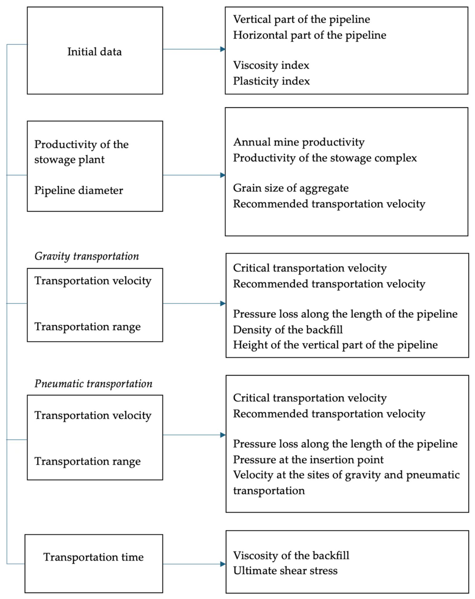
The calculation procedure is outlined below, and a diagram of the main indicators for gravity and gravity-pneumatic pipeline transport is shown (Figure 8).
The left column of the diagram (Figure 8) highlights the initial data and main transport indicators, such as velocity, transport distance, pipeline diameter, and plant capacity. The right column (Figure 8) defines the main quantities influencing these indicators. The compiled formulas for the pipeline transport calculation methodology consider both the rheological and granulometric characteristics of the backfill. The proposed calculation procedure is currently at the stage of theoretical development. The present formulas are the result of analytical derivations and generalization of known empirical dependencies for pipeline transport calculations [51,52,53,54,55].
Calculation Procedure:
  • Capacity of the backfill plant (productivity of the stowage plant)
The capacity of the backfill plant Q is a value that can be varied during calculations. However, it must be remembered that it equals the ratio of the production capacity of the backfill complex to the number of operating hours of the enterprise.
The production capacity of the backfill complex Q (m3/year) is determined by the following formula:
Q = P K t h u n K s h r ρ
where P is the annual mine productivity, t/year; ρ is the ore density, t/m3; K t h u n is the unevenness coefficient of mining ( K t h u n = 1.25–1.3); and K s h r is the shrinkage coefficient (for hardening backfill K s h r = 1.01–1.02).
2.
Pipeline diameter
The technical capacity of the backfill plant Q , the mixture movement speed v g r for gravity transport, and the pipeline diameter D are related by the following relationship:
Q = 3600 × π D 2 4 v g r .
Initially, during the first calculations, the pipeline diameter D is preliminarily assigned based on the recommended speeds for gravity transport. Based on operating experience, the optimal transport speed ensuring stable operation of the plant is set within v g r . r e c o m = 0.5–1.5 m/s.
The pipeline diameter is also recommended to be checked by the following ratio:
D 5 × δ
where δ is the size of the coarse aggregate grain, mm.
3.
Indicators of gravity transport
Transport speed
The speed of mixture movement during gravity transport is adopted based on the rheological characteristics of the mixture and the capacity of the backfill plant. The critical speed of mixture movement in the pipeline can be calculated using the following formula:
v g r . c r = 0.5 1 + C 0.36 g D E δ 4 ,
where C is the initial concentration of the mixture, %; g is gravitational acceleration, m/s2; D is the pipeline diameter, m; and E δ is the average drag coefficient, depending on the aggregate grain size.
The calculated speed of backfill movement through the pipeline:
v g r = 4 Q π D 2 3600
Based on operating experience, the optimal transport speed ensuring stable plant operation is set within v g r . r e c o m = 0.5–1.5 m/s. If the calculated speed is below the minimum allowable, it is necessary to increase the plant capacity.
Transport distance
The length of gravity transport horizontally can be calculated using the ratio N = L / H , which is approximated by the following empirical equation:
N = k f i l l × ρ λ × i
where k f i l l is the filling coefficient of the vertical pipeline section; ρ is the density of the backfill; λ is the local resistance coefficient; and i is the pressure loss along the pipeline length:
i = W 1 + C × v g r 2 E δ g D 1.4
The maximum gravity transport distance:
L g r m a x = N × H
If the calculated value L g r m a x is greater than the required transport distance L , then the condition for transport by gravity alone is confirmed. The transport time in this case is as follows:
t = L v g r
If L g r m a x < L , the condition for gravity-pneumatic transport is considered.
4.
Indicators of pneumatic transport
Transport speed
The transport speed v p n must be higher than the critical speed v c r i t . The speed of the air flow at which the particles of the transported material are in a suspended state is called the hovering speed. If a particle of material is likened to a sphere of diameter d (m), then the equilibrium equation of the sphere placed in an air medium in a pipeline can be written as follows:
π d 3 γ 6 g = γ a i r λ r e s g π d 2 4 v h 2 g
where γ is the density of the material, kg/m3; λ r e s is the resistance coefficient, depending on particle shape and surface condition; γ a i r is the air density, kg/m3 ( γ a i r = 1.2 ) ; and v h is the hovering speed, m/s, determined by the formula:
v h = v p n = 2 g d γ 3 γ a i r λ r e s
Based on operating experience, the optimal transport speed of the mixture on the pneumatic section, ensuring stable plant operation, is set within v r e c = 2–4 m/s. If the calculated speed is below the minimum allowable, it is necessary to increase the plant capacity.
Transport distance
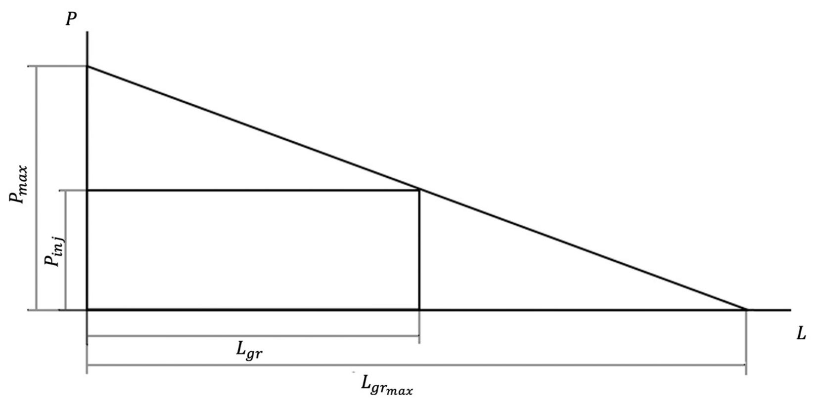
One of the most important calculated indicators is the distance from the vertical section of the pipeline to the first pneumatic injector. Since the transported mixtures have a lateral earth pressure coefficient К p = 1, the pressure loss in the pipeline obeys a linear law (Figure 9).
From the similarity of triangles:
L g r = L g r m a x 1 P i n j P m a x ,
where L g r is the desired length of the gravity section, m; L g r m a x is the maximum length of the gravity section of the horizontal pipeline, m; P i n j is the allowable pressure of the mixture at the injection point: P i n j = (0.7 ÷ 0.8)  ×  6 bar (let us take P i n j = 50,000 kg/m2); and P m a x is the maximum pressure of the mixture at the beginning of the horizontal pipeline section, kg/m2:
P m a x = r H 1 W 1 + λ × v g r 2
where r is the volumetric weight of the backfill mixture.
The maximum transport distance using one injector:
L p n = v p n v g r 1 P i n j P m a x 100
The transport time for gravity-pneumatic transport is calculated by the formula:
t = L g r v g r + n L p n v p n
where n is the number of injection points along the pipeline length.
The equations for pneumatic transport (18)–(23) are based on simplified assumptions: spherical particles, constant air density, and neglect of particle–wall friction. Therefore, these formulas are intended for preliminary estimates. For final engineering design, the calculated parameters must be validated by pilot loop tests using the actual backfill mixture. The proposed methodology is currently at the theoretical stage and awaits industrial-scale confirmation.

4. Discussion

4.1. Comparison with Published Studies

The numerical modeling carried out showed that the use of backfill in the room-and-pillar mining system of potash mines significantly changes the stress–strain state of the room pillars. The presence of the backfill mass creates additional reaction pressure, leading to higher initial stresses in the pillars but, in the long term, contributes to their unloading. However, the nature and speed of this unloading fundamentally depend on the type of backfill.
The comparison of three types of backfill (dry, hydraulic, and hardening) revealed significant differences. Dry backfill, despite its simplicity of implementation, practically does not reduce the stress in the pillars throughout the entire calculated period (over 50 years), which agrees with the known problems of shrinkage and caking of salt waste. Hydraulic backfill demonstrates more favorable behavior: pillar unloading begins 12 years after the start of extraction. This can be explained by the higher density and lower compressibility of hydraulically placed waste. This behavior is qualitatively consistent with the findings of studies [8,37,56,57,58,59] of various backfill materials based on salt waste. These same studies revealed that hardening backfill in potash mines accelerates stress redistribution and reduces the long-term load on pillars. This conclusion is supported by the present study.
The best results were obtained for hardening backfill: pillar unloading begins already after 5 years, and overlying rocks subsidence is minimal. This effect is explained by the ability of hardening backfill not only to fill the void but also to actively absorb rock pressure, acting as a bearing structural element. This finding is fundamental for ensuring the continuity of the water-protective stratum, as minimizing subsidence of the roof and the overlying water-protective rocks is the main condition for preventing flooding.
Quantitatively, the observed surface subsidence without backfill is comparable with the results reported in [45] for similar geological conditions. As in the present study, surface subsidence is approximately 40–60% of the extracted seam thickness. Moreover, the active subsidence period occurs within the first 10 years, after which the movements enter a decay stage.
The unloading of pillars due to the strength increase in the hardening backfill is supported by recent numerical studies [8,60,61,62]. The effectiveness of cemented backfill in reducing surface subsidence has been demonstrated in various mining conditions [63,64,65,66,67,68]. For instance, studies on coal mines have shown that cemented paste backfill can limit surface subsidence to levels acceptable for building protection. In the potash industry, subsequent backfilling operations have been reported to significantly reduce surface subsidence and enhance mine stability. Pilot-scale tests on consolidating backfill based on salt waste have also confirmed uniform roof subsidence and minimal shrinkage of the backfill mass. These findings are consistent with our numerical modeling results, which demonstrate a reduction of more than 50% in surface subsidence when using hardening backfill.
Concerning secondary pillar extraction, the proposal to leave narrow technological pillars is conceptually similar to the approach described in [4], which also recommended a staged extraction. However, we provide the temporary support (technological pillars) and an explicit analytical formula (Equation (5)) for calculating the required backfill strength as a function of pillar width and loading degree, which is a new contribution not presented in earlier works. The calculated strength is about 6 MPa, which is within the range of values (4–8 MPa) reported in [69,70] for hardening backfill, confirming the design feasibility.

4.2. Limitations and Applicability

Several limitations of this study should be acknowledged.
First, the numerical model assumes plane-strain conditions and an infinite regular grid of pillars and rooms. This neglects three-dimensional stress redistribution, end effects at panel boundaries, and the influence of geological heterogeneities (faults, folds, lithological variations). The adopted plane-strain model and the assumption of a conditionally infinite alternation of pillars and rooms provide an acceptable approximation for the central parts of extraction panels. In reality, however, pillars and mined-out spaces have finite dimensions along the strike, making edge effects significant. The plane-strain simplification does not account for three-dimensional stress redistribution along the strike, which may lead to either overestimation or underestimation of the actual bearing capacity of the pillars. In addition to three-dimensional effects, real conditions include geological heterogeneities and tectonic disturbances that can influence local stress distribution. To account for edge effects and achieve more accurate predictions, three-dimensional calculations are required, and 3D modeling is one of the priority directions for further research.
Second, the creep parameters were calibrated using subsidence data from a single Russian potash deposit. The general applicability of the calibrated values to other deposits with different salt compositions requires further verification on an expanded set of field data.
Third, the model does not include coupled hydro-mechanical effects, chemical degradation of the backfill over time, or thermal expansion, all of which could affect long-term stability.
Fourth, the pipeline transport equations, especially for the pneumatic section, are based on idealized assumptions and have not yet been validated with full-scale industrial tests. Therefore, the proposed transport methodology should be treated as a preliminary design tool, and final parameters must be confirmed by experimental tests. The design of pneumatic transport, including calculations of resistance losses in the pneumatic tract, compressed air consumption, and the methodology for determining the key parameters of the ejector, represents a separate complex engineering task that was beyond the scope of this study and is planned for subsequent work.
Fifth, the model accounts for the moment of contact between the backfill mass and the roof. However, a more detailed quantitative correlation over time between the strength gain rate of the backfill and the creep rate of the pillars is required [71,72]. In future research, it is necessary to develop a criterion coupling the time-dependent strength evolution equation of the backfill with the creep rate of the pillars to determine the minimum time required for the backfill to reach the necessary strength. At present, the period of roof subsidence onto the backfill mass can be estimated through the unloading period of the room pillars. According to the results of the previous study [73], hardening backfill reaches its design strength within 60–90 days, while hydraulic backfill based on salt waste requires 3 to 5 years. These periods are significantly shorter than the onset of unloading. For quantitative assessment, the empirical formula σ b a c k f i l l ( t ) , presented in Section 3.2, can be used, where α is an empirical rate constant determined from laboratory curing tests for the specific backfill composition.

4.3. Practical Implications and Remaining Challenges

Despite these limitations, the study provides a clear engineering pathway for improving potash recovery while maintaining safety. The proposed technology, if implemented with hardening backfill, can increase ore extraction by 20–30% (by extracting the previously left room pillars) [5] without jeopardizing the water-protective stratum, as the reduction in roof subsidence minimizes the risk of fracture formation. Future work should focus on:
3D numerical modeling to assess end-effects;
In situ monitoring of a pilot panel to verify the predicted pillar unloading and surface subsidence;
Investigation of the relationship between creep and backfill strength gain;
Experimental validation of the transport formulas using pilot-scale tests.
The proposed technology for extracting room pillars while leaving technological pillars represents a compromise between the desire for maximum mineral recovery and the need to ensure safety. This approach avoids dangerous dynamic roof falls characteristic of extraction adjacent to the backfill mass. This concept is analogous to “secondary mining” strategies. The technological pillars act as temporary supports.
Justification of the proposed technology is impossible without geomechanical investigations. Earlier studies on the influence of backfill on pillar loading and stress redistribution, as well as studies on roof subsidence in potash seams, employed similar numerical modeling mechanisms and show good agreement with the results presented here. Moreover, these studies indicate that with immediate backfilling of rooms, the stresses in the pillars increase only slightly compared with the level of natural stress [8,60,74], which confirms the feasibility of pillar extraction.
The derived formula for calculating the required backfill strength and the dependence on the loading degree of the technological pillar provide a basis for engineering design. However, the applicability of these relationships over a wide range of mining and geological conditions requires additional verification.
The problem of transporting hardening backfill deserves special attention. The work proposes new criteria for assessing the transportability of the backfill mixture: the plasticity index and the viscosity index. The presented calculation procedure for gravity and gravity-pneumatic transport systematically accounts for both the rheological and granulometric characteristics of the mixture for the first time. Nevertheless, the empirical formulas are based on generalized dependencies and require further experimental validation on real mixtures, serving as a basis for future industrial trials. The creation of a unified methodology for calculating the transport distance remains an urgent task.
From a practical standpoint, the implementation of hardening backfill, although technically advantageous, requires significant investment in the construction of a surface backfill plant and an extensive pipeline network. The proposed pipeline transport methodology provides a basis for designing this network; however, detailed design will require site-specific data for the given deposit. The potential increase in ore recovery must be weighed against the cost of backfill materials and operational complexity. However, the experience of potash mine development shows that savings on backfilling operations are incomparable with the financial losses incurred when a mine is flooded [2,75,76]. According to rough estimates, the lost profit from flooding a mine with approved reserves for 20 years of extraction amounts to about 60 billion rubles. According to the technogenic risk consequence assessment matrix [77], the probability of mine flooding, characterized by a frequency of 1 to 0.1 times per year and a financial loss to the enterprise of more than USD 100 million, should be classified as a very high risk that requires immediate implementation of risk-reduction measures and increased attention from the subsoil user. In view of the high flooding risks, the need to improve technologies with backfilling is undoubtedly justified.

5. Conclusions

Based on the results of the theoretical and numerical studies performed, the following main conclusions can be drawn:
  • Influence of backfill type on the stress–strain conditions of the mass. It has been established that hardening backfill provides the fastest reduction in stresses in room pillars (5 years after the start of extraction) compared to hydraulic (13 years) and dry (more than 50 years) backfill. Only hardening backfill creates a sustained reaction pressure sufficient to minimize subsidence of the water-protective stratum.
  • Increasing potash recovery. A new technology for mining room pillars is proposed, leaving technological pillars that are not intended for long-term load bearing but prevent dynamic roof falls. For the simulated conditions, it was established that a technological pillar with a width of 1.1 m and a loading degree of 0.64 is sufficient when the backfill mass strength is about 6 MPa.
  • Methodology for calculating backfill strength. An analytical dependence is derived that allows determining the required strength of the backfill mass based on the width of the technological pillar, mining depth, ore strength, and the structural weakening coefficient. This formula can be used in the design of mining systems with backfill.
  • Criteria for the transportability of hardening mixture. It is substantiated that the key indicator distinguishing a plastic (transportable) mixture from a granular one is the coefficient of lateral earth pressure К p . For plastic-viscous mixtures suitable for gravity and pneumatic transport, К p ≤ 1. The index of specific resistance (viscosity index) allows for the quantitative assessment of the resistance to mixture movement through the pipeline.
  • Engineering methodology for calculating transport. A calculation procedure for gravity and gravity-pneumatic transport has been developed, including the determination of the backfill plant capacity, pipeline diameter, critical and operating speeds, as well as the maximum transport distance for each section. The presented dependencies create a basis for subsequent implementation in regulatory documents.
  • Practical recommendation and remaining work. To ensure the safety of potash mines using a room-and-pillar mining system and to enable subsequent extraction of room pillars, hardening backfill with adjustable strength and rheological properties is recommended. Its implementation requires a dedicated surface backfill plant and a pipeline transport system. The proposed calculation procedure for gravity and gravity-pneumatic transport, although systematically derived, is presently at the theoretical stage; its parameters must be verified by large-scale tests before industrial application. Nonetheless, the presented methodology offers a rational basis for preliminary design and highlights the key parameters affecting mixture transportability.

Author Contributions

Conceptualization, D.A.S. and N.M.S.; methodology, D.A.S. and A.G.Z.; software, R.G.K.; validation, D.A.S., N.M.S. and E.E.P.; formal analysis, A.G.Z. and R.G.K.; investigation, D.A.S. and N.M.S.; resources, R.G.K. and E.E.P.; data curation, N.M.S. and A.G.Z.; writing—original draft preparation, D.A.S.; writing—review and editing, N.M.S., A.G.Z., R.G.K. and E.E.P.; visualization, R.G.K. and E.E.P.; supervision, D.A.S.; project administration, D.A.S. All authors have read and agreed to the published version of the manuscript.

Funding

This research received no external funding.

Institutional Review Board Statement

Not applicable.

Informed Consent Statement

Not applicable.

Data Availability Statement

The numerical modeling results and analytical derivations presented in this study are based on generalized parameters of typical potash deposits and can be reproduced using the methodology described in the article.

Conflicts of Interest

The authors declare no conflicts of interest.

References

  1. Prugger, F.F.; Prugger, A.F. Water problems in Saskatchewan mining—What can be learned from them? CIM Bull. 1991, 84, 58–66. [Google Scholar]
  2. Zubov, V.P.; Smychnik, A.D. The concept of reducing the risks of potash mines flooding caused by groundwater inrush into excavations. J. Min. Inst. 2015, 215, 29–37. [Google Scholar]
  3. Baryakh, A.A.; Smirnov, E.V.; Kvitkin, S.Y.; Tenison, L.O. Russian potash industry: Issues of rational and safe mining. Russ. Min. Ind. 2022, 1, 41–50. [Google Scholar] [CrossRef] [Scilit]
  4. Kovalski, E.R.; Kongar-Syuryun, C.B.; Petrov, D.N. Challenges and prospects for several-stage stoping in potash minining. Sustain. Dev. Mt. Territ. 2023, 15, 349–364. [Google Scholar] [CrossRef] [Scilit]
  5. Zubov, V.P.; Sokol, D.G. Technologies of intensive development of potash seams by longwall faces at great depths: Current problems, areas of improvement. J. Min. Inst. 2023, 264, 874–885. [Google Scholar]
  6. Lee, F.T.; Abel, J.F. Subsidence from Underground Mining: Environmental Analysis and Planning Consierations; Geological Survey circular 876; U.S. Geological Survey: Alexandria, VA, USA, 1983. [Google Scholar]
  7. Soloviev, V.A.; Sekuntsov, A.I.; Chernopazov, D.S. Development and application of sylvinite seams excavation technology with pillar-and-chamber method in Verchnekamsk potash deposit. News Ural State Min. Univ. 2013, 4, 41–46. Available online: https://iuggu.ru/index.php/archive/xxi-vek/2013/4-13/78-ru/195-4-13-07 (accessed on 8 July 2026).
  8. Kovalsky, E.R.; Kongar-Syuryun, C.B. Recovery of barrier pillar reserves during deep potash seam mining. Min. Sci. Technol. 2026, 11, 5–15. [Google Scholar] [CrossRef] [Scilit]
  9. Nyukalo, P.Y.; Ivanov, O.V. Application of a development system with a diagonal arrangement of producing stopes in the potash ore extraction. Bull. Tula State Univ. 2021, 4, 444–452. Available online: https://cyberleninka.ru/article/n/primenenie-sistemy-razrabotki-s-diagonalnym-raspolozheniem-ochistnyh-kamer-pri-dobyche-kaliynyh-rud (accessed on 8 July 2026).
  10. Belyakov, N.A.; Belikov, A.A. Prediction of the integrity of the water-protective stratum at the Verkhnekamskoye potash ore deposit. Min. Inf. Anal. Bull. 2022, 6, 33–46. [Google Scholar] [CrossRef] [Scilit]
  11. Zhang, Y.; Lapatsin, S.; Zhuravkov, M. The stability and failure of deep underground structures at potash mining deposits. Appl. Sci. 2024, 14, 9434. [Google Scholar] [CrossRef] [Scilit]
  12. Sirenko, Y.G.; Kovalsky, E.R. Improvement of selective potash extraction using shortwall mining with partial backfill. Gorn. Zhurnal 2016, 1, 24–26. [Google Scholar] [CrossRef] [Scilit]
  13. Ryl’nikova, M.V.; Berger, R.V.; Yakovlev, I.V. Backfill Technologies and designs for deep-level sylvinite mining. J. Min. Sci. 2024, 60, 332–340. [Google Scholar] [CrossRef] [Scilit]
  14. Baryakh, A.A.; Lomakin, I.S.; Samodelkina, N.A.; Tenison, L.O. Loading of rib pillars in multiple seam mining at the upper Kama salt deposit. Min. Inf. Anal. Bull. 2023, 1, 5–19. [Google Scholar] [CrossRef] [Scilit]
  15. Konstantinova, S.A.; Aptukov, V.N. Some Problems of Mechanics of Deformation and Fracture of Salt Rocks; Nauka: Novosibirsk, Russia, 2013; 191p. [Google Scholar]
  16. Gilev, M.V.; Konstantinova, S.A.; Marakov, V.E.; Chernopazov, S.A. Stowing of goaf during sylvinite seams mining as a structural element of mining system. Mine Surv. Bull. 2007, 1, 33–40. [Google Scholar]
  17. Karasev, M.A.; Petrushin, V.V.; Rysin, A.I. The hybrid finite/discrete element method in description of macrostructural behavior of salt rocks. Min. Inf. Anal. Bull. 2023, 48–66. [Google Scholar] [CrossRef] [Scilit]
  18. Kozlovskiy, E.Y.; Zhuravkov, M.A. Determination and verification of the calculated model parameters of salt rocks taking into account softening and plastic flow. J. Min. Inst. 2021, 247, 33–38. [Google Scholar] [CrossRef] [Scilit]
  19. Protosenya, A.G.; Katerov, A.M. Substantiation of rheological model parameters for salt rock mass. Min. Inf. Anal. Bull. 2023, 16–28. [Google Scholar] [CrossRef] [Scilit]
  20. Sidki-Rius, N.; Bascompta, M.; Sanmiquel, L.; Yubero, M.T. Definition of characteristic subsidence parameters. A case study in the Catalan potassium basin. Environ. Earth Sci. 2024, 83, 566. [Google Scholar] [CrossRef] [Scilit]
  21. Kovalskiy, E.R.; Kongar-Syuryun, C.B.; Sirenko, Y.G.; Mironov, N.A. Modeling of rheological deformation processes for room and pillar mining at the Verkhnekamsk potash salt deposit. Sustain. Dev. Mt. Territ. 2024, 16, 1017–1030. [Google Scholar] [CrossRef] [Scilit]
  22. Arguello, J.G.; Bean, J.E.; Stone, C.M.; Ehgartner, B.L. Geomechanical Analyses to Investigate Wellbore/Mine Interactions in the Potash Enclave of Southeastern New Mexico; Sandia National Laboratories Technical Report SAND2009-4795; Sandia National Laboratories: Albuquerque, NM, USA, 2009. [Google Scholar] [CrossRef] [Scilit]
  23. Onica, I.; Cozma, E.; Marica, D. Stability analysis of the rock salt rooms and pillars of the Ocnele Mari Saline with the aid of the 2D finite element modelling. Ann. Univ. Petroşani Min. Eng. 2011, 12, 7–17. [Google Scholar]
  24. Zhang, W. Long Term Deformation and Stability of Room and Pillar in Salt Mines; PLAXIS 2D application example; Bentley Systems Technical Note KB0045342; Seequent: Christchurch, New Zealand, 2025. [Google Scholar]
  25. Baryakh, A.; Telegina, E. Geomechanical justification of additional measures to protect potash mines from flooding. In Proceedings of the International Multidisciplinary Scientific GeoConference-SGEM, Albena, Bulgaria, 2–8 July 2018; Volume 18, pp. 443–450. [Google Scholar] [CrossRef] [Scilit]
  26. Baryakh, A.A.; Fedoseev, A.K.; Lobanov, S.Y. Deformations and fracture of rock strata during deep level potash mining. Procedia Struct. Integr. 2021, 32, 109–116. [Google Scholar] [CrossRef] [Scilit]
  27. Qu, H.; Yin, H.; Li, C.; Wang, W. Deformation characteristics and mechanism of salt structure: Research and discussion based on seismic analysis and tectonic simulation and implications for rock salt migration and mineralization in complex tectonic regions. Acta Geol. Sin. 2024, 98, 2916–2930. [Google Scholar] [CrossRef]
  28. Ilinov, M.D.; Korshunov, V.A.; Pospekhov, G.B.; Shokov, A.N. Integrated experimental research of mechanical properties of rocks: Problems and solutions. Gorn. Zhurnal 2023, 5, 11–18. [Google Scholar] [CrossRef] [Scilit]
  29. Saeed, S.; Negar, R.; Davood, Z.; Soheil, M. Mechanical behavior of salt rocks: A geomechanical model. Petroleum 2023, 9, 508–525. [Google Scholar] [CrossRef] [Scilit]
  30. Jeremic, M.L. Rock Mechanics in Salt Mining; CRC Press: Leiden, The Netherlands, 1994. [Google Scholar]
  31. Ghasemloonia, A.; Butt, S.D. Feasibility study of underground salt caverns in Western Newfoundland: Experimental and finite element investigation of creep-induced damage. J. Min. Environ. 2015, 6, 205–224. [Google Scholar] [CrossRef] [Scilit]
  32. Morozov, I.A.; Udarcev, A.A.; Pankov, I.L. Laboratory deformation testing of salt rocks from the Gremyachinsk and Upper Kama deposits. MIAB Min. Inf. Anal. Bull. 2020, 10, 16–28. [Google Scholar] [CrossRef] [Scilit]
  33. Morozov, I.A.; Pankov, I.L.; Toksarov, V.N. Stability of underground openings in salt rock masses. MIAB Min. Inf. Anal. Bull. 2021, 9, 36–47. [Google Scholar] [CrossRef] [Scilit]
  34. Ageenko, V.A. Justification of rheological test measurement parameters in incremental loading mode for rock salt. MIAB Min. Inf. Anal. Bull. 2021, 4, 113–123. [Google Scholar] [CrossRef] [Scilit]
  35. Ageenko, V.A.; Skvortsov, A.A. Rheological properties of rock salt under super long-term sustained uniaxial loading. MIAB Min. Inf. Anal. Bull. 2019, 11, 27–34. [Google Scholar] [CrossRef] [Scilit]
  36. Perevoshchikova, A.A.; Perevoshchikov, R.D.; Malyshkina, E.E.; Mitrakova, N.V. Waste management in potash mining companies. Bull. Tomsk Polytech. Univ. Geo Assets Eng. 2024, 335, 19–35. [Google Scholar] [CrossRef] [Scilit]
  37. Kovalski, E.R.; Gromtsev, K.V.; Petrov, D.N. Modeling deformation of rib pillars during backfill. MIAB Min. Inf. Anal. Bull. 2020, 8, 87–101. [Google Scholar] [CrossRef] [Scilit]
  38. Alieva, L.; Zhukov, I.A. Upgrading rotary-percussion drilling of high-strength rocks by improving the structure of a rock-crushing blade-free tool. Sustain. Dev. Mt. Territ. 2024, 16, 1681–1694. [Google Scholar] [CrossRef] [Scilit]
  39. Kovalsky, E.R.; Mironov, N.A.; Urazov, D.V.; Musinsky, N.A. Assessment of potential methods for driving main developments at deep levels of the designed Zapadno-Petrikovskoye potash mine deposit. Sustain. Dev. Mt. Territ. 2025, 17, 1033–1045. [Google Scholar] [CrossRef] [Scilit]
  40. Halabura, S.P. The Carnallitite Deposits of Saskatchewan: Resource Problem or Solution Mining Opportunity? In Proceedings of the SMRI Spring Technical Conference, Krakow, Poland, 26–28 April 2009. [Google Scholar]
  41. Kovalsky, E.R.; Mironov, N.A.; Urazov, D.V. On accounting for factors affecting the magnitude of floor heave in development workings when mining potash seams at great depths. Transp. Min. Constr. Eng. Sci. Prod. 2025, 35, 170–176. [Google Scholar] [CrossRef]
  42. Luangthip, A.; Wilalak, N.; Thongprapha, T.; Fuenkajorn, K. Effects of carnallite content on mechanical properties of Maha Sarakham rock salt. Arab. J. Geosci. 2017, 10, 149. [Google Scholar] [CrossRef] [Scilit]
  43. Cao, Z. The Bifurcation Characteristics and Dynamical Evolution Rule of Non-Isothermal Seepage Mechanical Model in Fractured Rock Mass. Processes 2026, 14, 1985. [Google Scholar] [CrossRef] [Scilit]
  44. Khayrutdinov, M.M.; Aleksakhin, A.V.; Kibuk, T.N. Technogenic waste in backfill composite is a paradigm of circular economy. Mining 2025, 5, 57. [Google Scholar] [CrossRef] [Scilit]
  45. Sidki-Rius, N.; Sanmiquel, L.; Bascompta, M.; Parcerisa, D. Subsidence Management and Prediction System: A case study in potash mining. Minerals 2022, 12, 1155. [Google Scholar] [CrossRef] [Scilit]
  46. Kratzsch, H. Bergschadenkunde; Springer: Berlin/Heidelberg, Germany, 1974; 582p. [Google Scholar]
  47. Golovaty, I.I.; Petrovskij, A.B.; Prushak, V.Y. Substantiation of the possibility of developing reserves of the Third potash horizon of the Starobin deposit, previously worked out by the chamber system. Proc. Natl. Acad. Sci. Belarus Phys.-Tech. Ser. 2019, 64, 497–510. [Google Scholar] [CrossRef] [Scilit]
  48. Toksarov, V.N.; Evseev, A.V.; Kuzmin, V.S. Determination of mechanical properties of salt rocks in the mined-out part of the mine field at the BKPRU-2 mine. Nauchnye Issled. Innov. 2011, 5, 154–156. [Google Scholar]
  49. Jin, R.; Wang, X.; Zhang, S. Slurry transportation characteristics of potash mine cemented paste backfills via loop test processing. Processes 2024, 12, 2929. [Google Scholar] [CrossRef] [Scilit]
  50. Schleinig, J.-P.; Höntzsch, S.; Barnasch, J. A new technology to increase the extraction rate in potash mining areas—An approach for a safe secondary mining concept. In New Challenges in Rock Mechanics and Rock Engineering, 1st ed.; Tomás, R., Cano, M., Riquelme, A., Pastor, J.L., Benavente, D., Ordóñez, S., Eds.; CRC Press: Boca Raton, FL, USA, 2024; pp. 772–777. [Google Scholar]
  51. Altshul, A.D. Hydraulic Resistances of Pipelines; Construction Literature Publishing House: Moscow, Russia, 1964; 168p. [Google Scholar]
  52. Ostermann, M. Bergbaumechanik; Springer: Berlin/Heidelberg, Germany, 1958; 576p. [Google Scholar]
  53. Kulikova, A.A.; Kovaleva, A.M. Use of tailings of enrichment for laying of the developed space of mines. MIAB Min. Inf. Anal. Bull. 2021, 2, 144–154. [Google Scholar] [CrossRef] [Scilit]
  54. Ermolovich, E.A.; Ermolovich, O.V. The study of rheological characteristics of stowing hydromix of «combinat kmaruda» ferruginous quartzites tailings. Sci. Bull. Belgorod State Univ. 2015, 9, 143–146. [Google Scholar]
  55. Soloviev, V.A. Methodological Guidelines for Mining Operations at the Mines of the Verkhnekamsk Potash Deposit/Ural Branch of VNIIG; Nedra Publishers: Moscow, Russia, 1992; 468p. [Google Scholar]
  56. Karasev, M.A.; Selikhov, A.A.; Bychin, A.K. Laboratory study of the backfilling material based on halite waste. Transp. Min. Constr. Eng. Sci. Prod. 2023, 23, 180–188. [Google Scholar] [CrossRef]
  57. Ilyinov, M.D.; Petrov, D.N.; Karmanskiy, D.A.; Selikhov, A.A. Physical simulation aspects of structural changes in rock samples under thermobaric conditions at great depths. Min. Sci. Technol. 2023, 8, 290–302. [Google Scholar] [CrossRef] [Scilit]
  58. Herget, G.; Munroe, S. Utilization of salt tailings backfill at Denison-Potacan Potash Company. In Innovations in Mining Backfill Technology; CRC Press: London, UK, 1989; pp. 335–342. [Google Scholar] [CrossRef] [Scilit]
  59. Verkholantseva, T.V.; Dyagilev, R.A. Influence of backfilling on seismic activity in potash mines. MIAB Min. Inf. Anal. Bull. 2016, 12, 115–123. [Google Scholar]
  60. Kovalsky, E.R.; Kongar-Syuryun, C.B. Reduction of mineral losses in the development of potash seams at great depth. Sustain. Dev. Mt. Territ. 2025, 17, 1852–1862. [Google Scholar] [CrossRef] [Scilit]
  61. Gusev, G.N.; Epin, V.V.; Tsvetkov, R.V. The results of long-term observations of uneven settlements of buildings located on the territory of the Verkhnekamskoye potash deposit in Berezniki. News Ural State Min. Univ. 2022, 3, 80–89. Available online: http://www.iuggu.ru/download/2022/3-67-2022/008.pdf (accessed on 8 July 2026).
  62. Toksarov, V.N.; Morozov, I.A.; Beltyukov, N.L.; Udartsev, A.A. Deformation of underground excavations under conditions of the Gremyachinsk potassium salt deposit. MIAB Min. Inf. Anal. Bull. 2020, 7, 113–124. [Google Scholar] [CrossRef] [Scilit]
  63. Aglyukov, K.I. Mining of Protective Pillars Using Compacted Backfill. J. Min. Sci. 2004, 3, 81–87. [Google Scholar]
  64. Sun, Q.; Zhou, N.; Song, W.; Zhao, X. Risk Assessment and Prevention of Surface Subsidence under Buildings by Cemented Paste Filling and Strip Mining Methods: A Case Study. Adv. Civ. Eng. 2021, 2021, 9965279. [Google Scholar] [CrossRef] [Scilit]
  65. Bodenstein, J.; Rauche, H.A.M.; Schreiner, W.; Eulenberger, K.-H. Reduction of Surface Subsidence and Brine Inflow Prevention in Potash Mines by Subsequent Backfilling. In Tailings and Mine Waste ‘01: Proceedings of the Eighth International Conference on Tailings and Mine Waste ‘01, Fort Collins, CO, USA, 16–19 January 2001; A.A. Balkema: Rotterdam, The Netherlands, 2001; pp. 171–178. Available online: http://www.gbv.de/dms/tib-ub-hannover/327751363.pdf (accessed on 16 February 2017).
  66. Tatarnikov, V.I.; Berger, R.V. Results of pilot-scale industrial tests on the physical and mechanical properties of consolidating backfill based on salt waste from the Gremyachinskoye deposit. Russ. Min. Ind. 2025, 5, 69–73. [Google Scholar] [CrossRef] [Scilit]
  67. Li, B.; Zhou, N.; Qi, W.; Li, A.; Cui, Z. Surface Subsidence Control during Deep Backfill Coal Mining: A Case Study. Adv. Civ. Eng. 2020, 2020, 6876453. [Google Scholar] [CrossRef] [Scilit]
  68. Zhu, C.; Zhang, J.; Taheri, A. Control effect of coal mining solid-waste backfill for ground surface movement in slice mining: A case study of the Nantun Coal Mine. Environ. Sci. Pollut. Res. 2023, 30, 27270–27288. [Google Scholar] [CrossRef] [Scilit] [PubMed]
  69. Ksenofontov, A.A.; Tronin, S.A.; Bondarenko, M.P.; Kudryashov, A.L. Development of an innovative technology for backfilling of the mined-out space using paste-like backfill mixtures and assessment of its technical, economic and environmental efficiency. Russ. Min. Ind. 2024, 5, 91–97. [Google Scholar] [CrossRef] [Scilit]
  70. Adigamov, A.E. Mathematical Method for Determining the Standard Strength of Backfill Considering Mining and Geological Factors. MIAB Min. Inf. Anal. Bull. 2008, 10, 204–206. [Google Scholar]
  71. Qi, C.; Guo, L.; Wu, Y.; Zhang, Q.; Chen, Q. Stability evaluation of layered backfill considering filling interval, backfill strength and creep behavior. Minerals 2022, 12, 271. [Google Scholar] [CrossRef] [Scilit]
  72. Minkley, W.; Mühlbauer, J.; Lüdeling, C. Dimensioning Principles in Potash and Salt: Stability and Integrity. Rock Mech. Rock Eng. 2016, 49, 4537–4555. [Google Scholar] [CrossRef] [Scilit]
  73. Kongar-Syuryun, C.B. Justification of the Technology for Flat Potash Seams Mining at Great Depths Ensuring a Reduction in Mineral Losses. Ph.D. Dissertation, Empress Catherine II Saint Petersburg Mining University, Saint Petersburg, Russia, 2026. [Google Scholar]
  74. Tien, D.L.; Trung, T.V.; Anh, S.D.; Babyr, N.V. Ground Pressure and Methods to Enhance Roof Stability in Mechanized Coal Mining. Int. J. Eng. Trans. A Basics 2026, 39, 862–869. [Google Scholar] [CrossRef] [Scilit]
  75. Korelskiy, D.; Mentsiev, A.; Dengaev, A.; Novikova, A.; Babyr, N. Land Assessment in Mining Regions Considering Ecology. Int. J. Eng. 2024, 37, 2344–2353. [Google Scholar] [CrossRef] [Scilit]
  76. Kowalewski, O.; Spiewanowski, P. Stock market response to potash mine disasters. J. Commod. Mark. 2020, 20, 100124. [Google Scholar] [CrossRef] [Scilit]
  77. Porter, M.; Lato, M.; Quinn, P. Challenges with use of risk matrices for geohazard risk management for resource development projects. In MGR 2019: Proceedings of the First International Conference on Mining Geomechanical Risk; Australian Centre for Geomechanics: Perth, Australia, 2019; pp. 71–84. [Google Scholar] [CrossRef] [Scilit]
Figure 1. Ground surface subsidence during the flooding: (a) First Berezniki potash mine. (b) “Solikamsk-2” mine [2].
Technologies 14 00505 g001
Figure 2. Room-and-pillar mining system: (a) Plan view [9] and (b) cross-section.
Technologies 14 00505 g002
Figure 3. Geometry of the studied model.
Technologies 14 00505 g003
Figure 4. Stresses in the room pillar.
Technologies 14 00505 g004
Figure 5. Graphs of subsidence of the overlying rocks for different types of backfill.
Technologies 14 00505 g005
Figure 6. Scheme of the cross-section of the seam during the extraction of room pillars (mining sequence from top to bottom).
Technologies 14 00505 g006
Figure 7. Hazardous zones formed during roof subsidence.
Technologies 14 00505 g007
Figure 8. Main indicators for calculating gravity and gravity-pneumatic pipeline transport.
Technologies 14 00505 g008
Figure 9. For calculating the length of the gravity section.
Technologies 14 00505 g009
Table 1. Strength and deformation properties of modeled rocks.
Young’s Module, MPaUltimate Tensile Strength, MPaCohesion, MPaFriction Angle, Deg.Density, kg/m3Poisson’s Ratio
Roof rocks80001.24.239.422000.35
Salt seam12,0001.34.338.822000.35
Floor rocks12,0001.24.339.722000.35
Table 2. Mining parameters.
ParameterValue
Depth of the seam, m350
Seam thickness, m5.0
Room pillar width, m8.0
Room width, m5.1
Lagging of backfilling from stopping, years1.0
Backfill rate (degree of filling)0.85
Disclaimer/Publisher’s Note: The statements, opinions and data contained in all publications are solely those of the individual author(s) and contributor(s) and not of MDPI and/or the editor(s). MDPI and/or the editor(s) disclaim responsibility for any injury to people or property resulting from any ideas, methods, instructions or products referred to in the content.