1. Introduction
The improvement of the performance properties of machine part functional surfaces is impossible without the consistent development of technological processing methods. Among the variety of technological methods, plastic deformation stands out advantageously, as it is used both for surface hardening and for forming the workpiece dimensions.
Hardening by surface plastic deformation methods is widely used in technological practice to change the structure and, consequently, the physical and mechanical properties of the surface layer material, microrelief, and surface roughness [
1]. Recently, severe plastic deformation has been used to form surface nanostructures [
2,
3,
4,
5] and to intensify diffusion processes [
6]. This improves the physical and mechanical properties [
7], wear resistance [
8,
9], contact fatigue [
10,
11], and corrosion resistance [
12] of machine parts operating under severe operating conditions. Combined hardening of machine parts is also known [
13], which forms surface layers with high wear resistance and low surface roughness, including those with coatings [
14,
15].
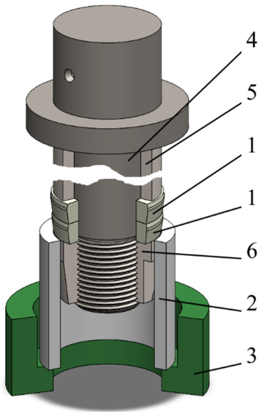
One of the forming methods is deforming broaching (DBR). DBR is a process of cold plastic deformation of holes in workpieces such as bushings and pipes, according to which the tool (deforming broach) moves along the generatrix of the machined hole (
Figure 1), following a sliding kinematic scheme [
16]. Typically, such a tool is equipped with one or several conical deforming elements made of high-hardness and high-strength tool material (for example, a tungsten carbide alloy of the WC group) [
17].
The diameters of these elements gradually increase and exceed the initial diameter of the workpiece by the interference value [
18]. During DBR, the dimensions of the part change (the hole diameter and the outer diameter of the part increase, and its axial dimension changes). Furthermore, the physical and mechanical properties of the surface layer of the hole and the workpiece core are improved, as well as the geometric characteristics of the machined surface layer [
19]. Therefore, DBR is used in both roughing and finishing operations, combining forming and strain hardening processes. DBR is applied to process parts made of plastic materials: steels, aluminum, and copper alloys with hole diameters from 5 to 200 mm; wall thicknesses reaching the hole diameter; and interferences ranging from small sizing ones to significant values, reaching up to 20% of the initial workpiece diameter during through-thickness deformation of the part. Additionally, this process is used for finishing operations of parts made of low-plastic materials: cast irons and hardened steels [
20]. When processing these materials, the surface layer of the hole is treated, i.e., finishing operations are performed with small interferences per element and minor total strains, which reduce the surface layer roughness and increase its hardness by 1.3–1.5 times the initial value [
21].
Modern approaches to the cold forming of holes in tubular workpieces are increasingly shifting the emphasis from describing the degree of deformation to a controlled relationship between technological parameters, the local stress–strain state in the deformation zone, and the final geometry after unloading. Therefore, recent studies have seen, on the one hand, the active development of statistical and optimization schemes that translate the geometric requirements of a product into a control system for technological factors, providing the engineer with rules for setting modes [
22,
23]. On the other hand, technological modifications of broaching are being actively investigated, where strains can be purposefully redistributed through tool geometry and the selected deformation scheme [
24]. A significant step was the introduction of criteria linking the choice of broaching modes and tool geometry with the level of contact stresses and the plasticity margin of the surface layer [
25]. For reliable prediction of forming, identified constitutive friction models are used, as well as experimentally confirmed assessments of the influence of tool design and the lubricant medium on the friction mode and axial force [
26,
27]. A similar methodology is demonstrated in studies of cold hole expansion, which directly lead to the prediction of elastic recovery and final diameter dimensions [
28,
29].
For technological methods of forming control to function not only as general recommendations but also to provide reproducible results in real products, it is necessary to rely on rigorous problem statements of technological mechanics, as developed in the works of Del [
30], Ogorodnikov [
31,
32], and Tsekhanov [
33]. In such problems, it is the combination of material deformability effects and the contact interaction between the tool and the part that determines the mechanics of the process. This interaction defines local contact pressure, friction conditions, sticking and slipping zones, and elastic recovery after unloading [
34,
35,
36]. This class of statements has a wide engineering spectrum of applications, ranging from shell dampers and shock absorbers to the processes of expansion and reduction of tubular workpieces, pipeline transport elements, bushings, casings, and thin-walled inserts where contact is the primary performance mechanism [
37,
38,
39,
40,
41]. At the same time, such problems are rarely simple, as they combine geometric thin-walledness, contact nonlinearity, tribological effects, significant non-uniformity of the stress–strain state, and the absence of boundary conditions [
42]. Therefore, theoretical solutions are usually possible only in idealized statements [
43]. Real cases mostly require numerical simulation and experimental verification as the final criterion of engineering reliability [
44,
45].
A group of authors, through the application of the finite element method (FEM) and process simulation, has refined the deformation zone during DBR [
46], studied the influence of operating parameters and workpiece wall thickness on the resource of used plasticity, and the associated conditions for defect-free deformation when processing steel [
47] and cast iron workpieces [
25]. It has been established that cast iron workpieces can only be processed by DBR with small interferences and minor total strains, thereby deforming only the surface layer adjacent to the hole [
25]. At the same time, workpieces made of plastic metals can be processed with significant through-thickness plastic deformations, during which the forming of the tubular workpiece dimensions occurs [
45].
Despite the importance of knowing the elements of forming, this important quality parameter that arises during workpiece deformation remains poorly studied. Therefore, an in-depth study of the plastic forming of tubular workpieces, which ensures the specification of their dimensional parameters, is relevant and timely.
Knowledge of this parameter allows for predicting the attainment of the required dimensions of the machined part and the allowance for subsequent machining, as well as utilizing this information when selecting the dimensions of the tubular workpiece.
In most early works regarding the determination of the dimensions of the machined workpiece [
17,
18,
48], only experimental models obtained by statistical processing of experiments were analyzed. This has its explanation. The history of the DBR process development shows that, initially, the issue of determining forming parameters was not relevant. This is due to the fact that the process was carried out using deforming elements made of hardened tool steels. As a result, only minor surface plastic deformations of the hole occurred, which allowed only for reducing surface roughness and increasing its hardness [
48]. The durability of such elements was low (dozens of linear meters of pipes). The capabilities of DBR were limited, and it was used only for processing with small surface plastic deformations; for example, the production of parts with simple shapes, such as bushings for agricultural machinery [
17].
With the widespread introduction of diamond tools into production [
17], the possibility of manufacturing and utilizing tungsten carbide deforming elements emerged [
17]. Improvements in their design [
16], based on experimental studies of the tool–workpiece interaction scheme and manufacturing technologies [
17], expanded the fields of DBR application. It became possible to perform significant (through-thickness) plastic deformations that substantially changed the dimensions of the machined workpieces. The processing of thick-walled parts made of difficult-to-machine materials under significant force loads began. The high wear resistance and strength of tungsten carbide deforming elements made it possible to process dozens of kilometers of pipes without noticeable wear [
49]. This significantly increased machining productivity and the precision of the processed products, while also reducing manufacturing costs [
50].
Thus, the application of roughing deforming broaching for processing tubular workpieces, accompanied by significant through-thickness strains, leads to a substantial plastic transformation of the tubular workpiece’s geometric parameters without metal removal in the form of chips [
16]. As a result, the out-of-roundness of the workpiece’s inner hole is reduced by 1–2 orders of magnitude, and the surface defect layer of metallurgical origin—including decarburized zones, pits, surface lamination, and other defects—is localized [
17]. At the same time, due to plastic deformation, the dimensions of the workpiece change, approaching the specified parameters of the finished part. The combination of these factors provides grounds for classifying this technological process as highly efficient in terms of metal saving, increased productivity, and the energy efficiency of production [
51].
The use of DBR for the roughing of deep holes in long parts—such as hydraulic and pneumatic cylinders, shock absorber and oil pump cylinders, mine props, drive shafts, special-purpose chambers, submersible pump housings, etc.—is hindered not only by increased requirements for the precision of the machined hole shape but also by the lack of capability to determine and control forming parameters during deforming broaching [
52].
Several approaches to determining workpiece forming parameters are known in the literature. According to the data provided in [
16], V.P. Monchenko suggests that the change in workpiece dimensions is determined by the part design, the processing scheme, and the degree of hole deformation. He recommends formulas for calculating the reduction in wall thickness and the workpiece shortening [
16]. However, the structure of the formulas in this approach only accounts for the degree of deformation and neglects the influence of the angle,
, and friction conditions, which limits their scope of application.
Results obtained using the known relationships proposed by E.A. Popov [
53] do not account for contact friction conditions and the processing scheme. Therefore, their analysis differs from the experimental results presented in [
17].
The analytical relationship for calculating workpiece shortening proposed by Yu.G. Proskuryakov [
18] provides satisfactory agreement with experimental data obtained during the deformation of thick-walled workpieces. At the same time, a comparison by the authors of [
17] between the calculation results using this relationship and experimental data for the deformation of thin-walled workpieces shows unsatisfactory results.
V.D. Shalaev [
54], when deriving analytical relationships, does not take into account the presence of non-contact zones in the deformation zone, and the calculation results obtained using these relationships differ from the experimental ones [
17].
Therefore, the authors of the study [
17] proposed using experimentally obtained relationships to calculate the workpiece dimensions after DBR to determine its forming. However, these relationships were obtained using the angle
recommended in most works and reflect the following nature of dimensional changes in the deformed workpiece: a decrease in wall thickness, an increase in outer and inner diameters, and a shortening of its length.
At the same time, data provided in other works [
55,
56] indicate a significant influence of the angle,
, on the dimensional changes of the deformed workpiece. It particularly affects the changes in axial dimensions. For instance, according to [
55], using angles
causes workpiece elongation instead of the generally accepted shortening.
The presented facts indicate that the plastic forming of workpieces during DBR not only determines the workpiece dimensions after broaching with significant through-thickness plastic deformations but can also ensure the control of obtaining the required dimensions through broaching modes and tool geometry. Furthermore, it can be used to select a tubular workpiece for further deformation processing. These dimensions, as noted above, are characterized by an increase in the inner and outer diameters and a decrease in the wall thickness of the machined workpiece. Regarding the axial dimension of the workpiece—namely, the axial strain component—most authors [
16,
17,
18] believe that shortening of the part occurs, i.e., a decrease in its initial length. However, as noted above, the authors of [
55,
56] have experimentally shown that in certain cases elongation of the part may occur.
The aforementioned contradictions do not allow for a clear formulation of the workpiece forming control scheme, i.e., achieving the required inner and outer diameters and the axial dimension of the part after its deformation. For a detailed study of this issue, it is necessary to analyze the processes occurring in the deformation zone and to examine the DBR deformation zone more profoundly.
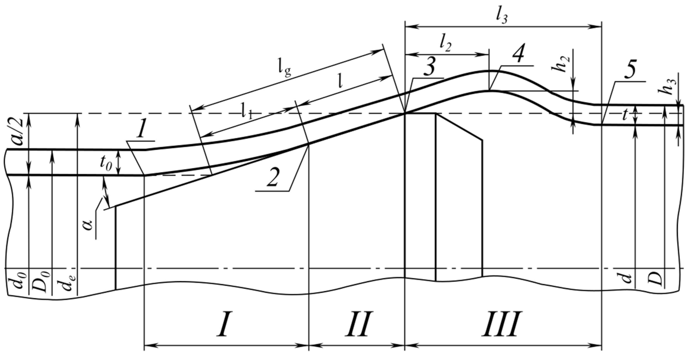
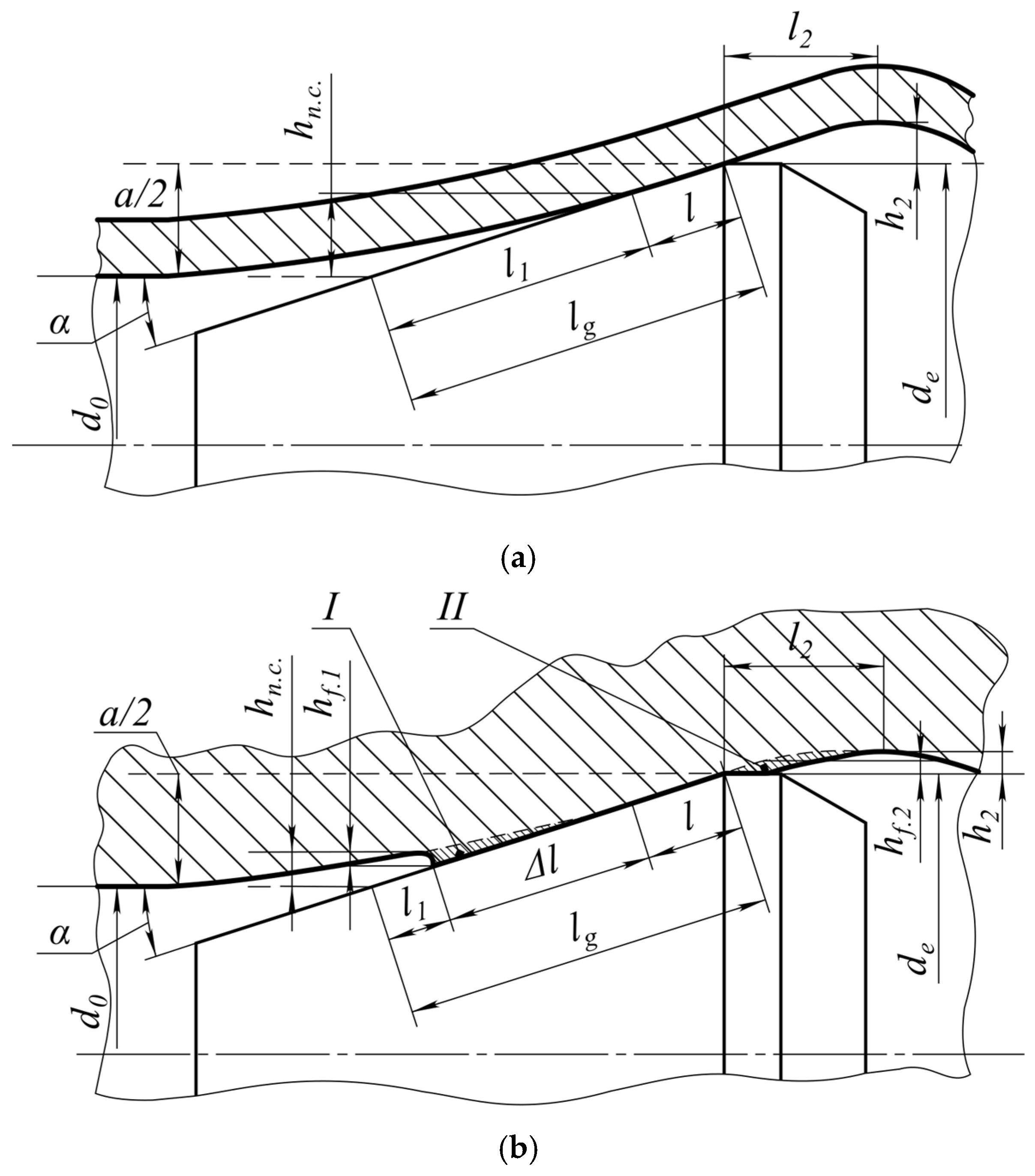
Our preliminary analysis to refine the deformation zone has shown that the most objective scheme of the deformation zone during DBR is one in which the zone consists of a contact area and two associated non-contact zones (
Figure 2) [
17]. The deformation zone comprises non-contact zone I, contact area II, and the subsequent non-contact zone III. It should be noted that the sections of the deformation zone are interconnected, depend on each other, and form a unified workpiece forming process; in other words, all dimensions of the machined part are formed within the deformation zone.
Furthermore,
Figure 2 indicates the initial dimensions of the workpiece:
represent the diameters of the hole, the outer surface, and the wall thickness, respectively; the interference per element is defined as the difference between the diameter of the cylindrical land of the deforming element,
, and the diameter of the initial hole of the workpiece.
The geometric contact length, , and the total contact zone length, , are also shown. The difference between them, , is due to the presence of the non-contact zone ahead of the contact area.
Regarding the non-contact zone following the contact area, its axial dimensions are designated as (the distance to its maximum height ) and (its total length). Furthermore, the elastic recovery of the part hole after machining, , is shown as the difference between the deforming element diameter, , and the hole diameter after machining, .
Therefore, establishing the deformation conditions within the deformation zone provides the opportunity to influence the attainment of the required dimensions through broaching modes and tool geometry. Previously, the authors of the studies [
16,
17] developed experimental methodologies for determining the dimensions of the deformation zone: contact length and non-contact zone parameters. The authors [
17] also proposed a classification of workpieces into three groups based on their wall thickness. The first group consists of shell-type workpieces with a wall thickness ratio
; the second group includes workpieces with finite wall thickness:
; and the third group comprises workpieces with infinite wall thickness:
. The stress states of each group have certain differences, but quantifying them without determining the stress–strain state (SSS) for each group is not possible. Based on experiments conducted on various materials, the authors of [
17] drew an important conclusion: the workpiece material has practically no effect on the length of the contact and non-contact zones.
Further refinement of the deformation zone was carried out computationally by the authors of [
57], who proposed a theoretical model of the deformation zone for the expansion of thin-walled shell-type workpieces. This model, constructed using variational principles [
58], allowed for the theoretical calculation of the geometric parameters of the deformation zone. However, a comparison of the obtained calculated values with experimental data showed good agreement for the contact area length and the height of the non-contact zone depending on the workpiece wall thickness only within the range of thin-walled workpieces. As the wall thickness increased, their values fundamentally differed from the experimental ones, meaning the theoretical model cannot be used for thicker-walled workpieces. The wall thickness beyond which the model becomes inapplicable is referred to by the authors of [
17] as the critical thickness, and it ensures the appearance of critical contact pressure in the contact zone. The authors of [
17] claim that the change in the monotonicity of the function
, where
is the contact length, is associated with the emergence of critical contact pressure in the contact zone, which causes an axial flow of material from the contact zone into the preceding non-contact zone in the form of a “bulge” (inflow). This increases the extent of the contact area and reduces the length of the non-contact zone ahead of it. Regarding the height of the non-contact zone following the contact area,
, experiments conducted by the authors of [
17] indicate that it also exhibits an extremal behavior depending on the wall thickness, but the reason for its appearance has not been determined by them. The presence of such discrepancies prevents the use of this theoretical model for analyzing processes occurring in the deformation zone over a wide range of workpiece wall thickness variations. Therefore, the strain calculations obtained using the theoretical model for the deformation of parts with finite wall thickness will be unreliable, and this model cannot be used for such cases.
Regarding the determination of axial strains, the presence of contradictions necessitates a more detailed study of the processes occurring in the deformation zone.
The presented data on the methods of controlling workpiece forming [
52,
55,
56] concern only specific processing cases, requiring further development and the establishment of their relationship with the technological factors of the DBR process.
The analysis of existing research indicates that the issue of plastic forming of workpieces during DBR is relevant and has attracted the attention of many authors. However, ideas regarding the deformation zone scheme remain contradictory: the theoretical model built on variational principles describes the deformation of thin-walled workpieces well but shows significant discrepancies with experimental data in the case of thick-walled ones. There is also uncertainty regarding the change in axial strain: some authors record the shortening of the part, while others note the possibility of its elongation.
Therefore, it is advisable to address forming problems during the through-thickness plastic deformation of workpieces with finite wall thickness based on an in-depth analysis of the mechanics of their plastic deformation. The complexity of the mathematical description of the volumetric plastic deformation process of thick-walled workpieces currently prevents the development of a theoretical model [
14,
15]. The successful use of the finite element method (FEM) to study the stress–strain state in technological processes similar to DBR [
41,
59], as well as during the deformation of parts made of gray cast iron Grade 200 [
25], indicates the possibility of its application for investigating the SSS during the deformation of the aforementioned workpieces across a wide range of modes, tool geometries, and wall thicknesses. The obtained results will provide a basis for the technological control of the workpiece’s plastic forming during DBR.
Therefore, the aim of the work is the technological control of workpiece dimensional changes by establishing a quantitative relationship between forming and the technological factors of the process: broaching modes, tool geometry, and workpiece wall thickness.
To achieve this goal, the work involves solving the following scientific and technical tasks:
Improving the existing methodology for studying the stress–strain state using the finite element method, and, based on it, determining and analyzing the SSS parameters of the workpiece on the inner and outer surfaces;
Identifying the characteristic features of the deformation mechanics of workpieces with a specified finite wall thickness on the inner and outer surfaces;
Establishing the regularities of the influence of operating parameters on the changes in the geometric dimensions of the inner and outer surfaces of the machined workpieces;
Analyzing the deformed state of the workpieces after machining and identifying the factor that determines the change in their axial dimension;
Developing a methodology for the technological control of the workpiece plastic forming process which will ensure the determination of rational broaching modes and tool geometric parameters to obtain the required dimensions of the machined workpieces.
2. Materials and Methods
Investigation of the SSS parameters of cylindrical tubular workpieces made of plastic material during DBR was performed using FEM based on the improvement of the methodology presented in [
47,
60], utilizing the DEFORM 2D/3D™ version V 11.0 software package (Company Scientific Forming Technologies Corporation (SFTC), headquarters in Columbus, OH, USA) [
61]. The effectiveness of using this software package for solving similar problems has been convincingly demonstrated in [
44,
45] and other studies.
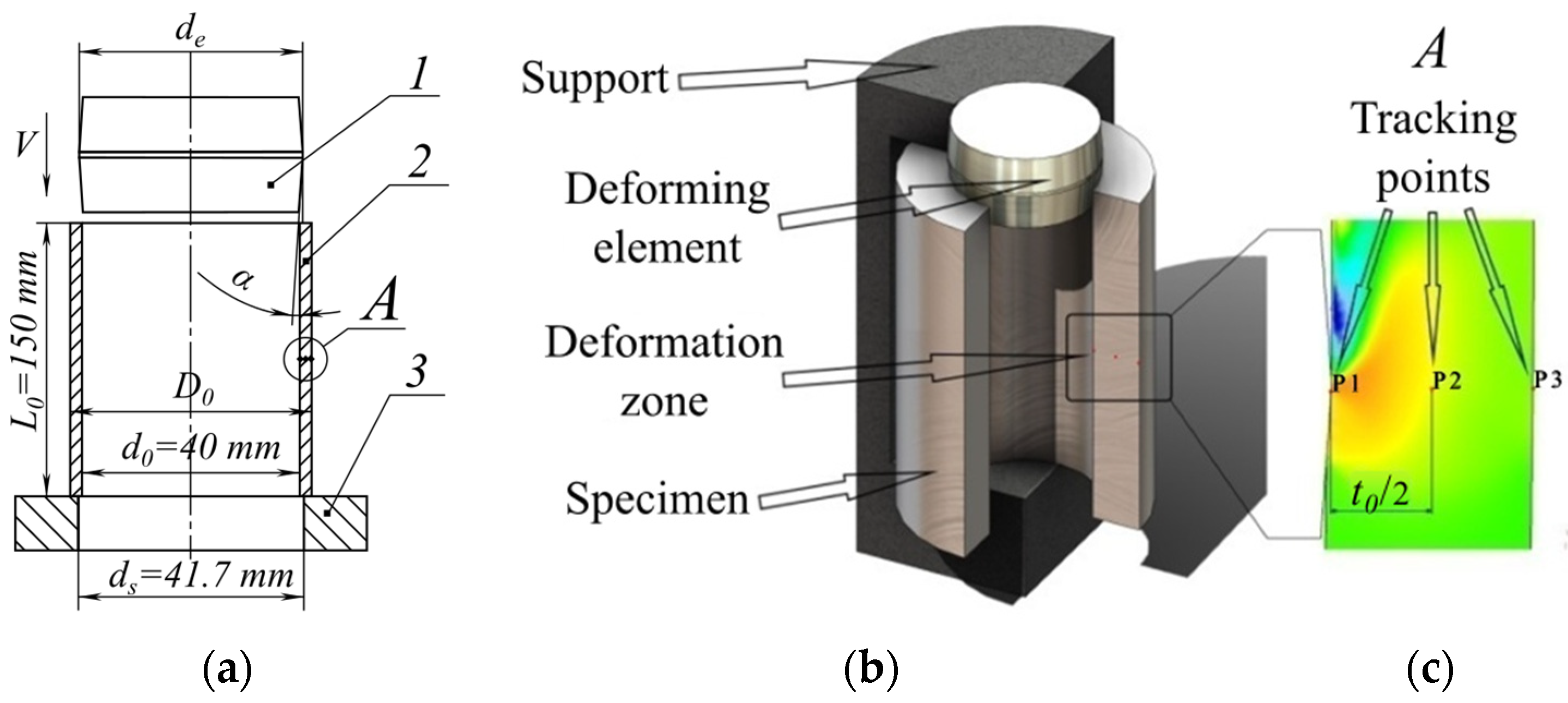
First, finite element simulation models were constructed according to the scheme shown in
Figure 3. The simulation of processing workpieces with various dimensions, which are processed by deforming elements with various angles, α, and broaching modes, was considered. The data for simulation are presented in
Table 1.
The deforming element is designed as two cones with a cylindrical land between them. The front cone is the working one with a generatrix inclination angle,
. The width of the cylindrical land is 0.9–1.1 mm. According to the recommendations in [
17], the deforming element is made of WC15 cemented carbide. The displacement speed of the deforming element was
mm/s.
Indeed, it would have been better to perform the deformation simulation using the data for 12ChN3A steel; however, the chemical composition and mechanical properties—the Brinell hardness, tensile strength, Poisson’s ratio, and Young’s modulus, as follows from
Table 2—are close to each other, which practically does not affect the magnitude of the critical contact pressure. Moreover, the experimental verification of the simulation model was performed by comparing the axial strains obtained during the simulation of the deformation process of workpieces made of DIN 14NiCr14 steel from the software library with the experimental results obtained during the deformation of workpieces made of 12ChN3A steel to determine axial strains under various modes, tool geometries, and workpiece wall thicknesses, showed the adequacy of the obtained results. Also, the results of comparing the contact zone length,
, obtained during the deformation process simulation with the contact zone length,
, obtained experimentally showed the adequacy of the obtained model. A comparison of the results obtained from simulating the process using a simulation model with experimental results is presented in
Section 3.
Steels 12ChN3A and 14NiCr14 were chosen as the material for the investigated part; its chemical composition and mechanical properties are presented in
Table 2.
Based on similar mechanical characteristics, the analogous DIN 14NiCr14 steel was selected from the DEFORM 2D/3D™ V 11.0 material library and was subsequently used for SSS modeling. The model of the constitutive properties of this material was also taken from the DEFORM library in the form of a table, the data of which are given in
Table 3 and describe the flow curve of this material. It was used in the DEFORM 2D/3D™ V 11.0 software to simulate the process. It should be noted that, according to the methodology in [
47], the SSS analysis was performed at the midpoint of the workpiece length at three points: P1—on the hole surface, P2—at the mid-wall thickness, and P3—on the outer wall surface (
Figure 3c).
A certain decrease in stresses after a strain of 0.4 is possible due to the well-known fact noted in works [
62,
63,
64], which are dedicated to the study of material deformation regularities during cutting and the description of material models in machining. This fact is characteristic of steels that contain impurities of other elements in their composition. In the initial state, these impurities move toward dislocations, forming the so-called Cottrell cloud. Upon the application of an external load, the specimen passes through the elastic region and transitions into the plastic one, thereby reaching the yield strength of the material. With further plastic deformation, a dislocation breakaway from these clouds occurs, meaning that dislocations are released from the vicinity of impurity atoms, and subsequent plastic deformation requires lower energy consumption, which is reflected by a slight decrease in load on the flow curve. We did not investigate this physical process but used the flow curve as a phenomenological factor for conducting the simulation.
The mesh was generated such that there were at least 10 finite elements per 1 mm on the outer surfaces of the workpiece. Thus, with a specified broaching speed of 0.5 mm/s and a time step of 0.25 s/step, the deforming element covers a distance slightly larger than the size of a single finite element in one step. The sizes of the finite elements gradually increased towards the core of the workpiece, with the largest elements being 3–4 times larger than the surface ones.
At each point, the hydrostatic pressure, ; stress intensity, ; strain intensity, ; axial stress, ; stress state stiffness coefficient, ; axial strain, ; circumferential strain, ; and radial strain, , were determined.
The height of the non-contact zone following the contact area was determined based on modeling results by tracking the displacement of pre-defined points [
46], specifically point 1 on the inner surface of the workpiece. The radial displacement of the points from their initial position (before processing) determined the height of the non-contact zone behind the deforming element.
The stress state stiffness coefficient,
, of the processed material was calculated according to the following formula [
65]:
where
is the hydrostatic pressure. The value of the hydrostatic pressure was determined by the following formula:
is the stress intensity, which is determined by the following formula:
The strain intensity,
, was determined by the formula presented in [
66]:
where
is the strain intensity and
are the radial, circumferential, and axial components of the strain tensor, respectively.
Wear, elasticity of the deforming element, and the temperature of the process, which belongs to cold plastic deformation, were not taken into account in the process simulation for studying the SSS. Therefore, the object type was chosen as elastic–plastic, while the deforming element and the support were chosen as absolutely rigid. Another constraint is the movement of the deforming element through the workpiece with an interference. In our case, shear friction conditions within the workpiece material itself are absent during the deformation of even thick-walled workpieces. This was confirmed by the conducted experiments when broaching workpieces with various wall thicknesses using sulfofrezol lubrication. The process proceeded without any adhesion of the workpiece material to the tool surface, and traces of material adhesion on the tool surface were absent. Therefore, the Coulomb friction model can be used. In the presence of a lubricating medium, the friction coefficient is
. Among other settings is the movement speed of the deforming element,
mm/s; according to the data of the authors [
17], the movement speed of the deforming element in the range from 0.03 m/min to 5 m/min does not significantly affect the deformation process. The established conditions allowed for the generation of a database and the initiation of the DBR simulation process.
To confirm the validity of the simulation models and results obtained during the numerical simulation, a comparison was made with experimental research data. Specifically, the axial strain values of the workpiece during the deformation of thin-walled and thick-walled samples were compared with the corresponding experimental results.
To experimentally verify the obtained results, an experimental methodology for determining the axial strain of processed workpieces using the visioplasticity method [
65] was employed. To conduct an experimental verification of the simulation models by comparing the calculated data of the workpiece length change with the experiment (
Table 4,
Table 5 and
Table 6), we analyzed the data obtained during the deformation of tubular workpieces with an inner diameter of
mm and various wall thicknesses,
: 0.05, 0.2, and 0.35. Data with
were used once, those with
were used seven times, and data with a wall thickness of
were used once. Each experiment was repeated 3 times, meaning that 3 workpieces with
, 21 workpieces with a wall thickness of
, and 3 workpieces with a wall thickness of
were manufactured. A total of 27 bushings (steel 12ChN3A) were manufactured from seamless hot-deformed pipe (DSTU 8938:2019) [
67].
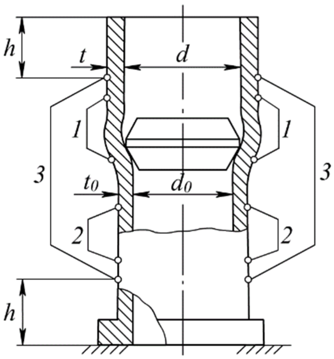
Boring and turning of the workpieces were performed on a 16K20 lathe with a cutting speed of 80–100 m/min and a feed rate of 0.19 mm/rev. The hole shape deviation of the workpiece did not exceed 0.025 μm, and the roughness of the batch of workpieces was approximately uniform (the height parameter, Ra, was in the range of 4–8 μm). Prior to deforming broaching, three pairs of marks (1, 2, and 3) were applied to the outer surface of the workpiece along its generatrix using a cemented carbide indenter at various distances from each other (
Figure 4). To avoid the influence of deforming element misalignment during bushing expansion on the measured distance, the marks were applied diametrically opposite each other; the distance between these marks was determined as the arithmetic mean of the distances measured between the diametrically applied corresponding marks. The marks were located at a distance,
, from the ends of the workpiece, ensuring the absence of the edge effect during workpiece deformation.
Based on the change in the distance between the diametrically placed corresponding marks after the bushing expansion, the relative axial strain of the investigated workpiece was determined as
, where
(
is the change in the initial axial dimension
to
after the workpiece deformation). The measurement of mark coordinates was performed using a BMI-1 toolmaker’s microscope (LOMA, Leningrad, USSR) with an accuracy of
. The length of the investigated workpiece was at least 150 mm. In accordance with the recommendations in [
16], the distance, h, from the outer marks to the ends of the workpiece exceeded the hole diameter, which excluded the influence of the edge effect on the experimental results.
Furthermore, the axial strain of the workpiece was determined experimentally based on the constant volume principle after deformation:
where
is the initial length of the workpiece and
is the length of the workpiece after deformation.
Then, . When comparing the calculated results with the experimental ones, the values obtained by two methods were taken into account: the visioplasticity method and the method based on the constant volume of the workpiece after deformation.
To reduce the number of simulations, the theory of similarity and dimensional analysis was used, which has found wide application in various research fields today [
60,
68,
69]. Below is an example of applying the theory of similarity and dimensional analysis to determine the axial strains of workpieces.
According to the data in [
17], the DBR process can be considered static, and the low temperatures in the contact zone (not exceeding
) allow it to be classified as cold plastic deformation. As shown by experiments in study [
17], the kinematics of the deformation process for workpieces with a finite wall thickness is practically independent of the material, which is confirmed by the independence of the tool–workpiece contact length from the material. Therefore, the geometric parameters of the machined workpiece should depend on the following initial geometric parameters: length,
; hole diameter,
; wall thickness,
; and technological parameters: interference,
, and total interference,
, as well as the angle,
, of the deforming element. Thus, the length of the workpiece after expansion is
If the length of the zones where the edge effect occurs is insignificant compared to the initial length of the workpiece,
, the deformation process will be stationary, and the length of the workpiece after deformation,
, will be proportional to
. In this case, function (2) changes and takes the following form:
The hole diameter,
, was chosen as the governing parameter, through which all other geometric parameters were expressed in dimensionless form. Then, function
changes to function
and takes the following form:
Given the above, the axial strain
will be
where
is the change in function
after the performed transformations.
The relationship (5) provides the grounds for conducting simulations of workpiece deformation using only one diameter with different relative geometric parameters and angles, , of the deforming element.
In addition, to verify the accuracy of the results obtained through the simulation of the simulation model, an experimental determination of the contact zone length was used, followed by its comparison with the contact zone length obtained from the simulation results. For verification, a method was used that consists in applying diamond-containing spots to the inner surface of the workpiece. Next, the workpiece is deformed, and the contact traces left by the diamond-containing spots on the surface of the deforming element are measured.
3. Results and Discussion
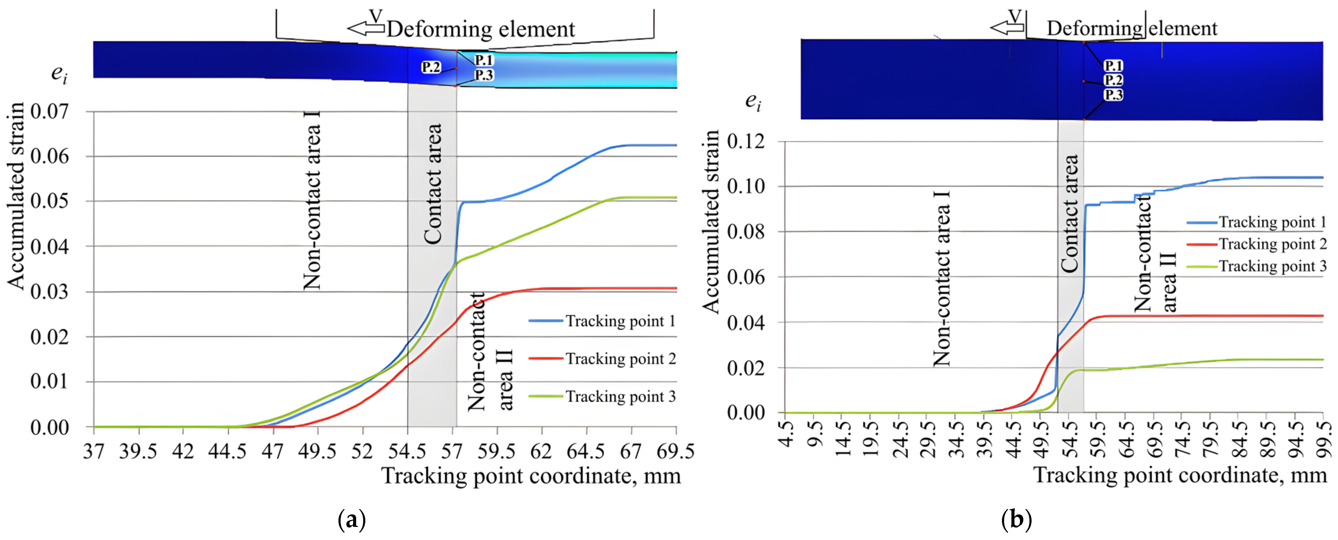
To study the SSS in the deformation zone during the simulation of the workpiece deformation process, let us consider the accumulated strain in the deformation zones of thick-walled and thin-walled workpieces, followed by an analysis of the simulation results.
Figure 5 illustrates the nature of the accumulated strain change during the deformation simulation of thin-walled and thick-walled workpieces.
The deformation process begins with the entry of the deforming element into the workpiece hole at the inlet end. At the same time, the axial broaching force begins to increase. It varies in the area adjacent to the inlet end, meaning that the deformation zone begins to form there (
Figure 2). After the deformation zone is fully formed, a steady-state deformation process begins, which continues until the deforming element approaches the support end. The process simulation and experimental study were performed in the presence of a steady-state deformation process, that is, at some distance from the inlet and support ends of the workpiece. In this case, the deformation zone presented in
Figure 2 was investigated. Similarly, the deformation of the simulation model began, reflecting changes in the stress–strain state of the processed workpiece. This allowed for the determination of the following SSS characteristics of the workpiece at the macro level: hydrostatic pressure,
; stress intensity,
; strain intensity,
; axial stresses,
; stress state stiffness coefficient,
; axial strain,
; circumferential strain,
; and radial strain,
.
An analysis of the data presented in
Figure 5 shows that the accumulated strain process begins in the non-contact zone I, followed by the realization of the main part of plastic deformation in the contact zone II, while the formation of the deformed state within the deformation zone is completed in the non-contact zone III. It is worth noting that the values of accumulated strain in the non-contact zones I and III are close to each other. A comparison of the results shown in
Figure 5a,b indicates a similar nature of the accumulated strain change for both thin-walled and thick-walled workpieces, although certain differences can be observed between them.
It has been established that in both investigated cases, the maximum values of accumulated strain are recorded on the inner surface of the workpiece. As the workpiece radius increases, the level of accumulated strain naturally decreases. The deformation process of thin-walled workpieces is characterized by certain specific features (
Figure 5a): on their outer surface (tracking point 3), the accumulated strain exceeds the corresponding values on the mid-wall surface (tracking point 2). For thick-walled workpieces, this pattern is not observed—in this case, the strain gradually decreases with increasing wall thickness, reaching minimum values on the outer surface of the workpiece (tracking point 3). At the same time, in thin-walled workpieces, the strain distribution throughout the wall thickness is practically through-thickness and close to uniform. In addition, the axial dimensions of the deformation zone during the deformation of workpieces with various wall thicknesses differ from each other; moreover, for thick-walled workpieces, they are significantly larger than for thin-walled ones. The difference in the axial dimensions of the deformation zone can be observed in
Figure 5,
Figure 6 and
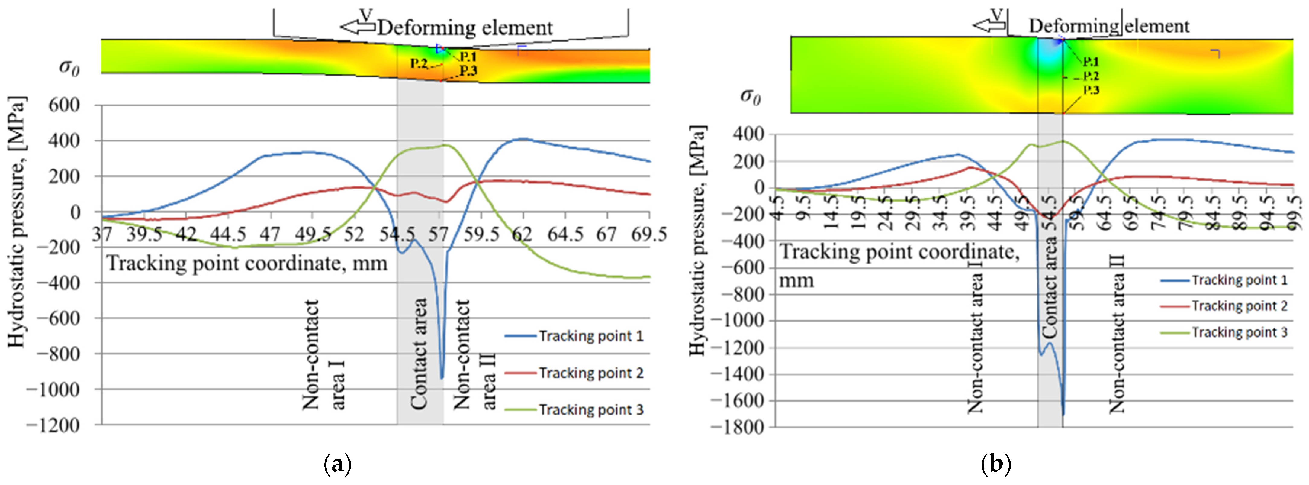
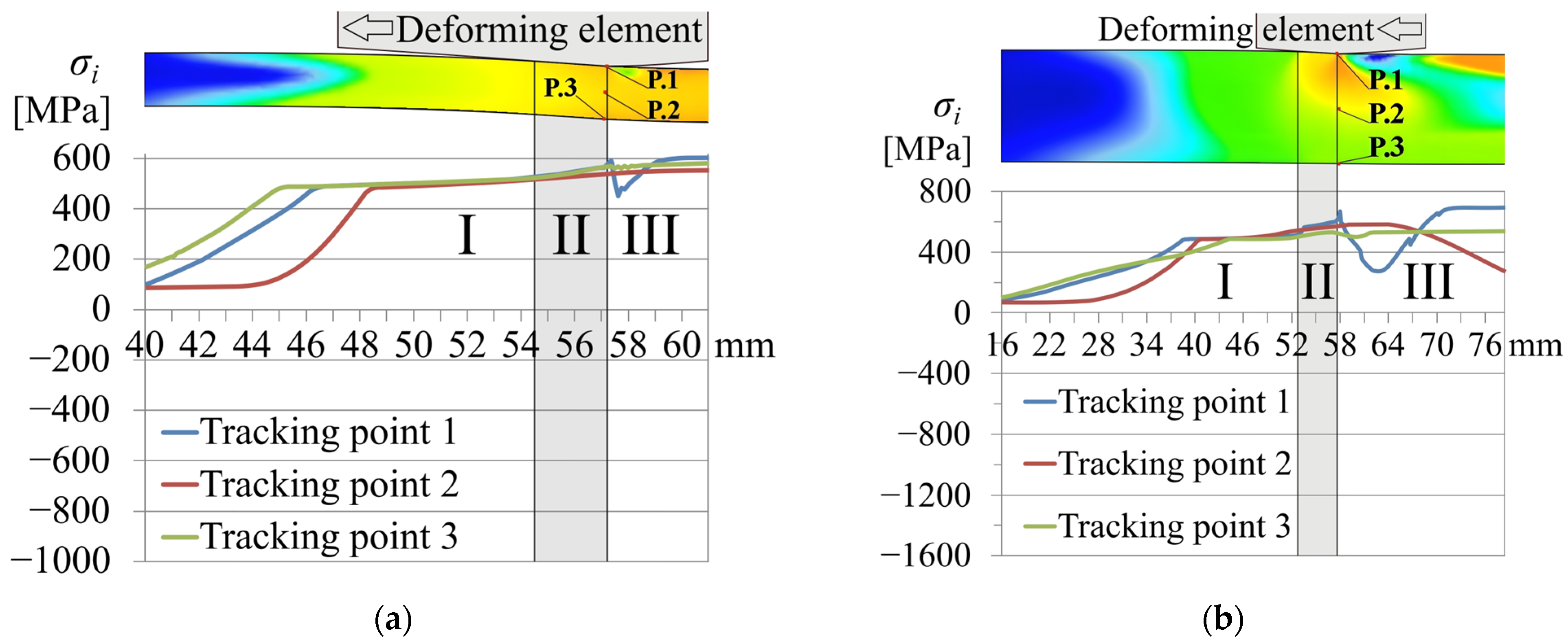
Figure 7. Analysis of the hydrostatic pressure (
Figure 6) shows that for thin-walled workpieces, its values vary from −1000 MPa in the contact zone to 400 MPa in the non-contact zones, while for thick-walled workpieces, the corresponding range is from −1600 MPa to 400 MPa, which is due to the increase in contact pressure as wall thickness increases.
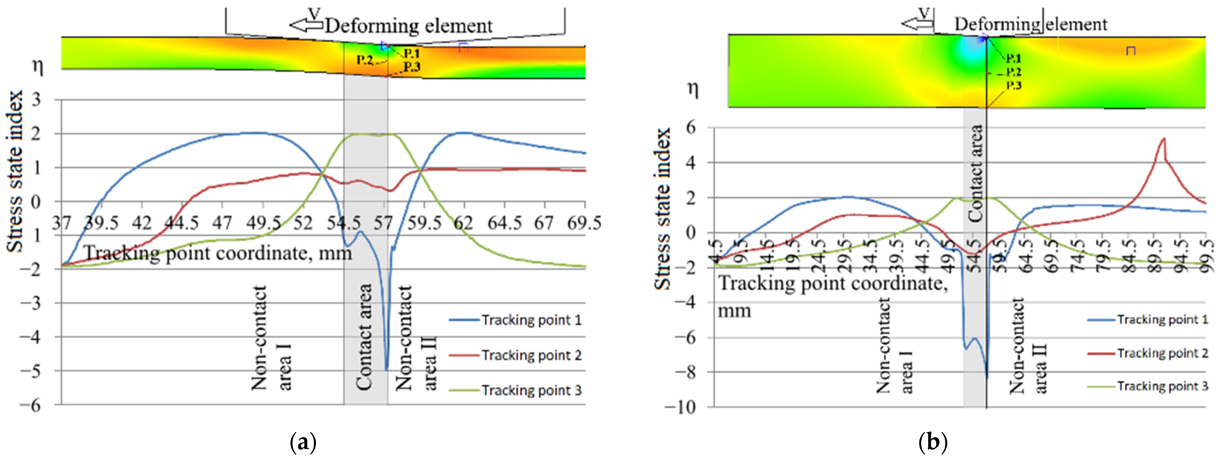
The stress state indicator in both cases (
Figure 7) on the outer surface of the workpiece, which corresponds to the contact zone, is
, while on the inner surface, where the maximum hole deformation occurs,
(
Figure 7a) and
(
Figure 7b).
In the thick-walled part, on the mid-wall surface (tracking point 2), the hydrostatic pressure value is close to zero; accordingly, the stress state indicator also approaches zero, while the accumulated strain at this point exceeds its value on the outer surface (tracking point 3). In contrast, for the thin-walled workpiece, a positive hydrostatic pressure can be observed at points 2 and 3, which is due to a more uniform through-thickness strain distribution. At the same time, at point 3, the hydrostatic pressure value is higher, leading to the formation of a stress state close to biaxial tension, which is confirmed by the value of the stress state indicator .
Having considered certain aspects of the deformed state, let us determine which technological factors influence its change, that is, which factors can be used to control the plastic deformation process. To do this, let us consider the influence of operating parameters, tool geometry, and workpiece wall thickness on the components of the strain tensor. These data are presented in
Table 4,
Table 5 and
Table 6.
As follows from
Table 4, with an increase in the workpiece wall thickness, a difference can be observed in the values of the strain tensor components, as well as in the strain intensity itself. Moreover, the data in
Table 4 indicate that increasing the wall thickness leads to a change in the deformed state. For instance, during the processing of thin-walled workpieces, two compression strain components,
and
, and one tension component,
, occur. Furthermore, while the processing of thin-walled workpieces results in workpiece shortening, an increase in wall thickness initially leads to the absence of axial strain change (zero axial strain), which subsequently shifts to elongation as the wall thickness continues to grow.
As follows from
Table 5, the angle,
, which defines the tool geometry, also influences the deformed state of the workpiece. Thus, when processing a workpiece with the same wall thickness, interference, and an angle
, a slight shortening of the workpiece is observed, characterized by two compression components,
and
, and one tension component,
. With an increase in the angle to
, axial strain is absent, and the strained state is characterized only by two equal values with opposite signs:
(tension) and
(compression). Subsequently, with an increase in the angle to
, elongation of the part occurs, characterized by two tension strain components,
and
, and one compression component,
.
The data in
Table 6 also indicate that the deformed state depends on the interference per element. Specifically, applying an interference of
leads to the appearance of two tension components,
and
, and one compression component,
. The presence of such components results in axial elongation strain. With an increase in the interference per element to
, the elongation decreases, and a zero change in length is observed; that is, the deformed state is characterized only by two equal values with opposite signs:
(tension) and
(compression). Increasing the interference to
leads to the shortening of the part, characterized by two compression components,
and
, and one tension component,
.
The provided data indicate that the specified technological factors significantly influence the SSS of the workpiece. In addition to these, according to our research [
47], the SSS of the processed workpiece is influenced by the total strain,
, i.e., the number of deformation cycles, which are determined according to the following relationship:
Similar relationships are applied to determine each of the components of the stress and strain tensors. For example, if a required axial strain is specified and during the first cycle of deformation with an interference it has a value of , then to meet the necessary technical requirements for this operation, it is necessary to broach three deforming elements with an interference of each, resulting in a total strain of .
Such a significant influence of each of the three identified technological factors is explained by their impact on the level of contact loads. As shown by our research [
46], during the deformation of thin-walled parts, the contact pressure is insignificant and less than the critical value; in this case, the deformation zone (
Figure 8a) represents a smooth transition of the non-contact zones with the contact area. The height of the non-contact zone ahead of the contact area is
, the height of the non-contact zone behind the contact area is
, and its length is
. Below is a geometric interpretation of the deformation zone parameters (
Figure 8). According to
Figure 8a, the contact length,
, is equal to
where
is the geometric contact length, equal to
.
As noted above, with an increase in the wall thickness,
, and the angle,
, and a decrease in the interference,
, the contact pressure increases according to the data in [
17]. When it reaches its critical value, the contact length,
, begins to increase due to the material flow into the non-contact zone ahead of the contact area (
Figure 8b). In this case, the contact length is determined according to
Figure 8b:
where
is an additional component of the increased contact length, which accounts for the height of the inflow and simultaneously reduces the length of the non-contact zone,
, and its height,
.
The height of the non-contact zone behind the contact area,
, for this case (
Figure 8b) also changes, decreasing due to the material flow from the contact zone onto the cylindrical land of the deforming element. Therefore:
where
is the height of the material flow from the contact area into the non-contact zone behind it. It should be noted that the length to the maximum of this non-contact zone does not change in this case.
As the authors of [
17] claim, the value of the critical contact pressure depends on the processed material in addition to the aforementioned technological factors. This means that a specific value of critical contact pressure corresponds to each material. According to [
17], this value corresponds to the hardness of the material in the neck of a specimen of the investigated material fractured during uniaxial tension. Moreover, according to their claims, the critical contact pressure is a physical constant of the processed material. Therefore, reaching the critical contact pressure in the contact zone, as shown by simulation results and experimental studies [
46], causes axial material flow from the contact area into the non-contact zones, as shown in
Figure 8b. At the same time, as shown above, the length of the non-contact zone ahead of the contact area decreases due to the material flow,
, and the height of the non-contact zone behind the contact area also decreases due to the material flow,
.
In turn, the contact pressure is directly related to the hydrostatic pressure, which has a high negative value in the contact zone:
MPa for thin-walled parts (
Figure 6a) and
MPa for thick-walled parts (
Figure 6b), as well as with the stress state indicator
for thin-walled parts (
Figure 7a) and
for thick-walled parts (
Figure 7b). This indicates that, in the contact zone, the material is under conditions close to all-around compression. Therefore, as the material leaves the contact zone, the high negative values of hydrostatic pressure and the stress state indicator decrease sharply and even become positive (
Figure 6 and
Figure 7). This change in these parameters leads to a change in the stress–strain state, the appearance of local plastic deformation zones at the junctions of the non-contact zones with the contact area, which are formed due to the material flow from the contact area into the non-contact zones.
Experimental verification of the simulation model was conducted in our work by comparing the results of axial strains determined during the simulation of the deformation process of workpieces with various wall thicknesses, processed under various modes and tool geometries, with the experimentally determined values of the corresponding axial strains (
Table 4,
Table 5 and
Table 6). The results obtained during the simulation and the experiment coincided, which indicates the adequacy of the simulation model. In addition, the experimental verification of the simulation model was performed in our work [
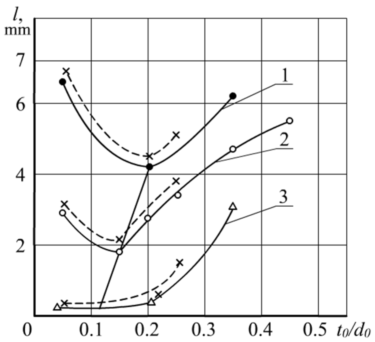
46] by comparing the contact zone length values obtained during the deformation process simulation with the experimentally obtained contact zone length values when using the method of diamond-containing spots applied to the inner surface of the workpiece. The calculated and experimental results almost coincided; a certain deviation of the experiments from the calculation is due to the slight protrusion of diamond grains above the hole surface. The graph of the contact length dependency on the wall thickness is presented in
Figure 9. The calculated character of the contact zone length change depending on the wall thickness coincides with the experimental one. The minor discrepancy between the calculated and experimental values of the contact zone length is due to the protrusion of diamond powder grains above the inner surface of the workpiece.
As noted above, the plastic forming of workpieces processed by DBR consists in changing the dimensions of the workpiece after its deformation. In the case of through-thickness strain, this involves changes in the dimensions of the outer and inner diameters, and accordingly, the wall thickness and the axial dimension of the workpiece.
Managing the forming process of the workpiece consists in establishing the influence of technological factors, namely, broaching modes and tool geometry, on the change in workpiece dimensions. That is, establishing such an influence provides the ability to assign the interference per element, total interference, and tool geometry that ensure the required dimensions of the processed workpiece.
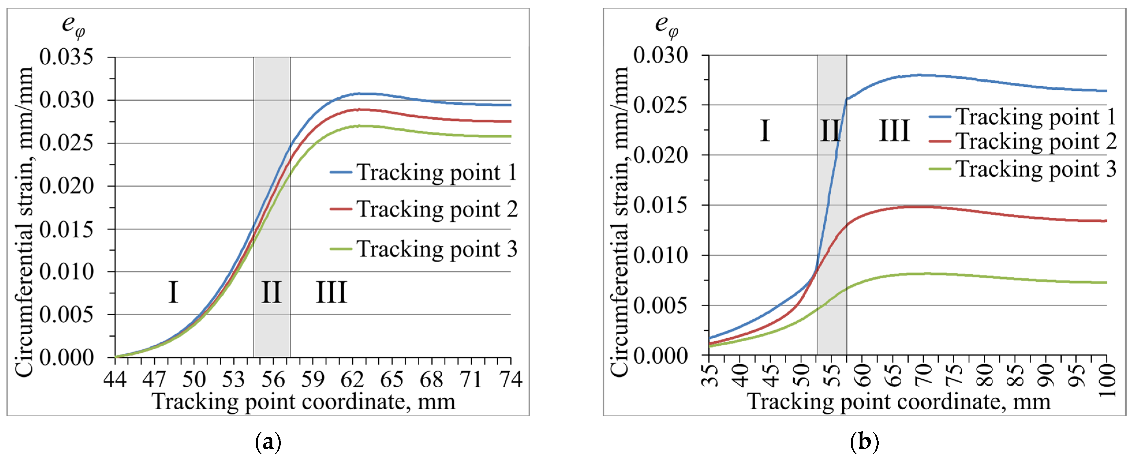
To this end, let us analyze the change in the dimensions of the outer surface of the processed material under the influence of technological factors. First, we will consider the variation in the circumferential strain component of the strain tensor, which determines the increase in the outer diameter of the workpiece.
Figure 10 presents the results of simulating the deformation process of thin-walled and thick-walled workpieces. It shows the deformation zone and its components, which are labeled as follows: II—the contact area (also shown in gray shading), and the non-contact zones I and III connected to it. The deformation zone and its components are shown in this way in several other figures.
It has been established that the overall nature of the change in the specified parameter does not depend on the workpiece wall thickness. At the same time, for thin-walled workpieces, the difference between the
values at tracking points 1, 2, and 3 is insignificant, which indicates a through-thickness uniform nature of deformation (
Figure 10a). For thick-walled workpieces, a significant difference between these values can be observed: the maximum
value corresponds to the inner surface, while the minimum corresponds to the outer surface (
Figure 10b). The largest values of circumferential strain are recorded in the contact zone, while in the non-contact zones the
is insignificant.
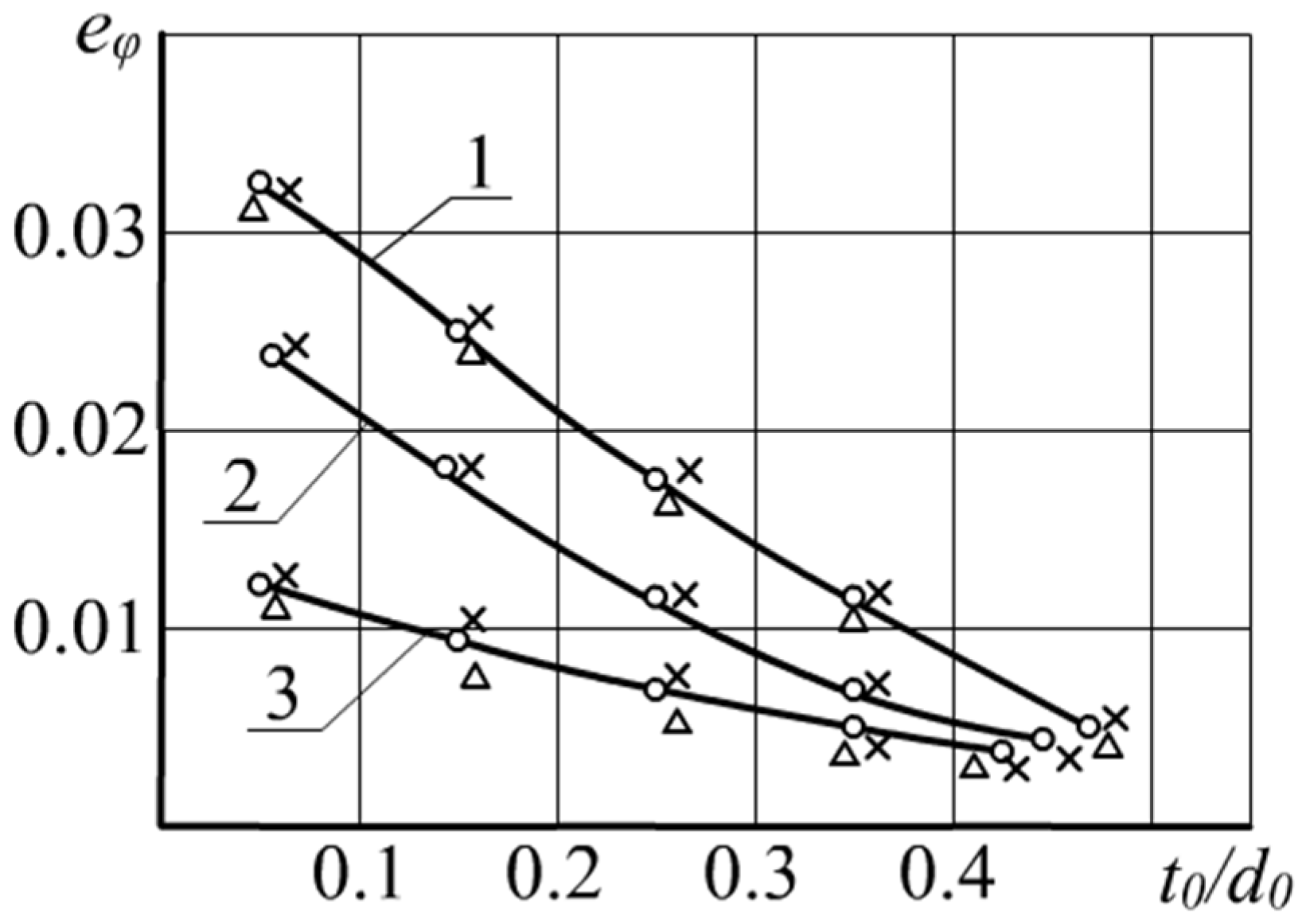
The influence of the technological process parameters and the geometric characteristics of the tool on the value of the circumferential strain of the outer surface is illustrated in
Figure 11. From the analysis of the provided data, it follows that the circumferential strain of the outer surface practically does not depend on the value of the angle,
, but is primarily determined by the wall thickness of the workpiece and the value of the interference per element. Additionally, according to relationship (6), the value of the circumferential strain is also influenced by the total interference.
Approximation of the calculated data presented in
Figure 11 made it possible to obtain an analytical relationship, the accuracy of which is up to 8%. Using it, the required interference can be determined depending on the given value of the circumferential strain:
The required total strain of the inner surface, which ensures the necessary deformation of the outer surface, is determined from Equation (7):
During the development of the technological process for workpiece processing or the restoration of worn parts, the value of the circumferential strain, which forms the allowance for further machining, is first determined [
16]. After that, using relationship (8), the required total interference is calculated to ensure the specified circumferential strain for a specific workpiece. If several deformation cycles are required, the total interference is distributed among individual cycles according to the following relationship:
As a rule, deforming broaching with through-thickness strains is used as a roughing operation, during which a significant exhaustion of the resource of used plasticity of the material occurs. According to the results presented in [
70], in the case of subsequent thermal or thermochemical treatment after DBR, it is necessary to limit the resource of used plasticity accumulated at the previous stages. According to the recommendations in [
47], the limit value of the resource of used plasticity for the outer and inner surfaces of the part is determined by the following formula:
where
and
is the limit strain of the workpiece, corresponding to a specific stress state indicator during its deformation.
Exceeding this value leads to a sharp deterioration in the mechanical properties of the part material after thermal treatment, which is explained by the author of [
70] as being due to the growth of the material’s grain size. This complicates diffusion processes during thermal and thermochemical treatment operations.
Therefore, after the hole expansion operation, it is necessary to check the hole deformation for the resource of used plasticity according to the methodology in [
47].
Let us consider the issue of determining the size of the processed hole after its plastic expansion. To do this, let us analyze the interaction scheme between the tool and the workpiece (
Figure 2). It follows from the figure that the non-contact zone behind the contact area increases the diameter of the deforming element by twice the value of its height. After the completion of plastic deformation, elastic recovery of the processed hole occurs. Based on this scheme, the authors of [
16,
17] propose a geometric relationship for determining the diameter of the processed hole in parts with a finite wall thickness:
where
is the doubled height of the non-contact zone behind the deforming element, mm, and
is the elastic recovery of the processed hole, mm.
During the deformation of workpieces made of plastic materials with significant through-thickness strains, the height of the non-contact zone, according to the data in [
17], is measured in tenths of a millimeter and has a significant impact on the size of the processed hole. Depending on its magnitude and the value of elastic recovery, the hole diameter may turn out to be smaller (hole shrinkage) or larger (hole oversizing) than the diameter of the deforming element [
17]. As follows from
Figure 10, the change in the generatrix of the hole material particle within the deformation zone, which replicates the change in the values of the circumferential strain component of the strain tensor, clearly indicates the presence of a non-contact zone behind the deforming element and elastic recovery. However, using these data to determine elastic recovery is not possible because they correspond only to the circumferential strain component, whereas the intensity of accumulated strains, which corresponds to the stress intensity, consists of three strain components: circumferential,
; radial,
; and axial,
. Therefore, to obtain a reliable result for determining elastic recovery, the well-known methodology proposed by the authors of [
17] was refined.
A.M. Rosenberg and O.A. Rosenberg (1991) [
17] proposed the following relationship for calculating the elastic recovery of a processed hole after its plastic deformation:
where
is the stress determined from the flow curve obtained during the tension testing of a specimen of the investigated material, corresponding to the total strain of the bushing
at the average diameter;
is the Young’s modulus of the processed material,
N/mm
2;
is Poisson’s ratio; and
is the ratio of the inner and outer diameters of the workpiece,
.
where
and
are the initial hole diameter and wall thickness, respectively, and
and
are the hole diameter and wall thickness after deformation, respectively.
Equation (11) has certain drawbacks and limitations during its use. First, to determine , it is necessary to know the strain at the average diameter of the processed workpiece; that is, to determine , which is subsequently used to determine elastic recovery, it is necessary to deform the bushing, which introduces certain difficulties. Furthermore, determining the strain at the average diameter involves certain errors, which in turn introduce inaccuracies when determining . To obtain the flow curve of the processed material of the workpiece, it is necessary to perform tension testing operations on a test specimen made of the processed material (steel).
Therefore, this methodology was improved by using the simulation results of the workpiece deforming broaching process. Knowing the stress intensity (
Figure 12), we determine
MPa for thin-walled workpieces and
MPa for thick-walled workpieces and substitute the required value into relationship (11) to calculate the elastic recovery.
Using the similarity theory [
65,
69], we obtain a dimensionless relationship of elastic recovery based on the process factors and workpiece dimensions:
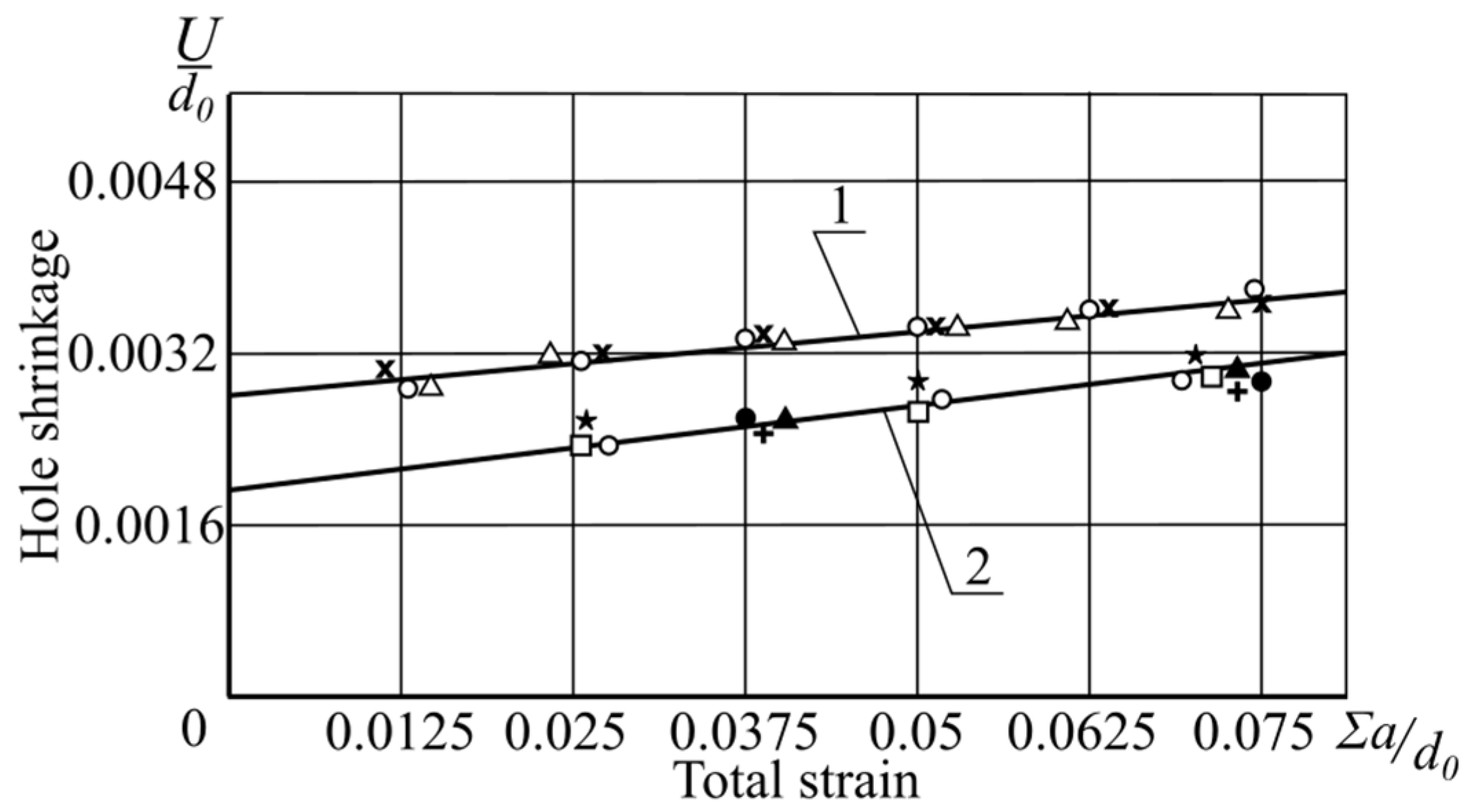
Figure 13 presents the results of determining the elastic recovery depending on the total strain when performed by a different number of deforming elements with various interferences.
Statistical processing of the simulation results shown in
Figure 13 made it possible to obtain interpolation relationships for calculating the elastic recovery: (13) for graphical dependency line 1 and (14) for graphical dependency line 2 (
Figure 13):
As follows from
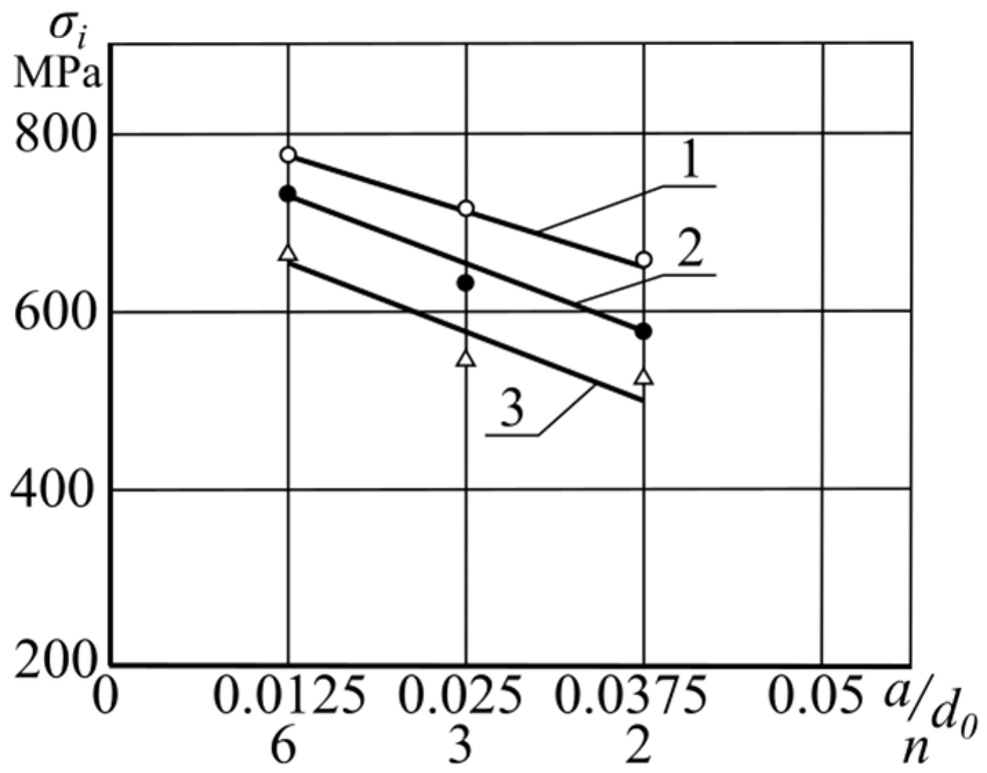
Figure 13, the elastic recovery increases proportionally with the growth of the total interference, which is explained by the work hardening of the processed material as the hole deformation increases. Moreover, when performing the same total strain with a larger number of deforming elements by reducing the interference per element, the stress intensity value,
, also increases proportionally, regardless of the workpiece wall thickness (
Figure 14).
The highest stress intensity value corresponds to a higher wall thickness, i.e., .
With an increase in the interference per element, i.e., with a decrease in the number of elements performing the total strain, the smallest value of
corresponds to an interference per element of
. This is reflected in the
calculations, where the elastic recovery corresponding to the case when the total strain is performed by the maximum number of elements (
Figure 13, curve 1) is higher than the elastic recovery corresponding to interferences of
and
(
Figure 13, curve 2).
Statistical processing of the
calculation results shown in
Figure 14 made it possible to obtain relationship (15), according to which the
value for a specific interference and workpiece wall thickness can be calculated:
The next component included in relationship (10) required to find the diameter of the processed hole is
—the doubled height of the non-contact zone behind the deforming element. The determination of this component was carried out according to an improved methodology for determining the change in the generatrix within the deformation zone and recording the excess height of the non-contact zone over the diameter of the deforming element.
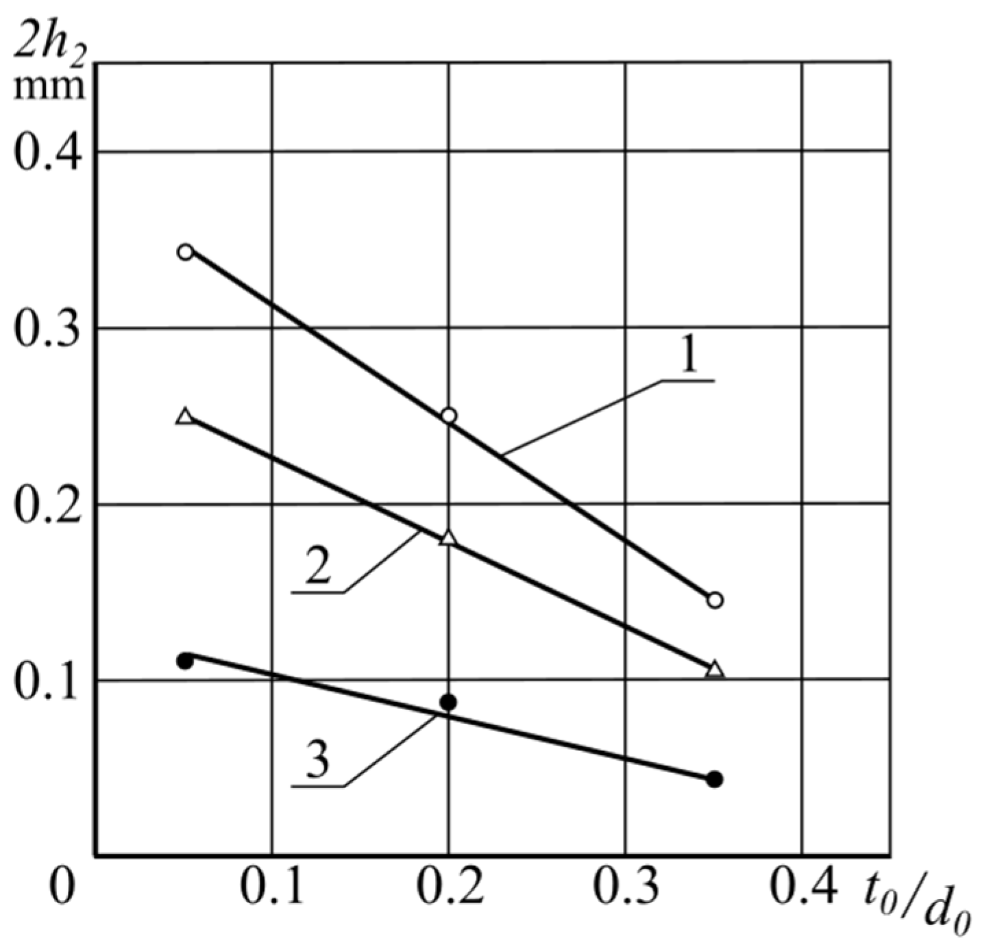
Figure 15 presents the dependency of the parameter
on the workpiece wall thickness. It follows from this that with an increase in the workpiece wall thickness, the parameter
decreases proportionally. This is also confirmed by the calculated data presented in [
46] and the experimental data presented in [
17], where the graphical dependency of this factor on the wall thickness is non-monotonic. However, the data shown in
Figure 15 are characteristic of wall thicknesses starting from
and increasing accordingly. In this wall thickness range, the data from [
17,
46] and the data shown in
Figure 15 coincide.
Statistical processing of the results shown in
Figure 15 made it possible to obtain a relationship for determining the parameter
:
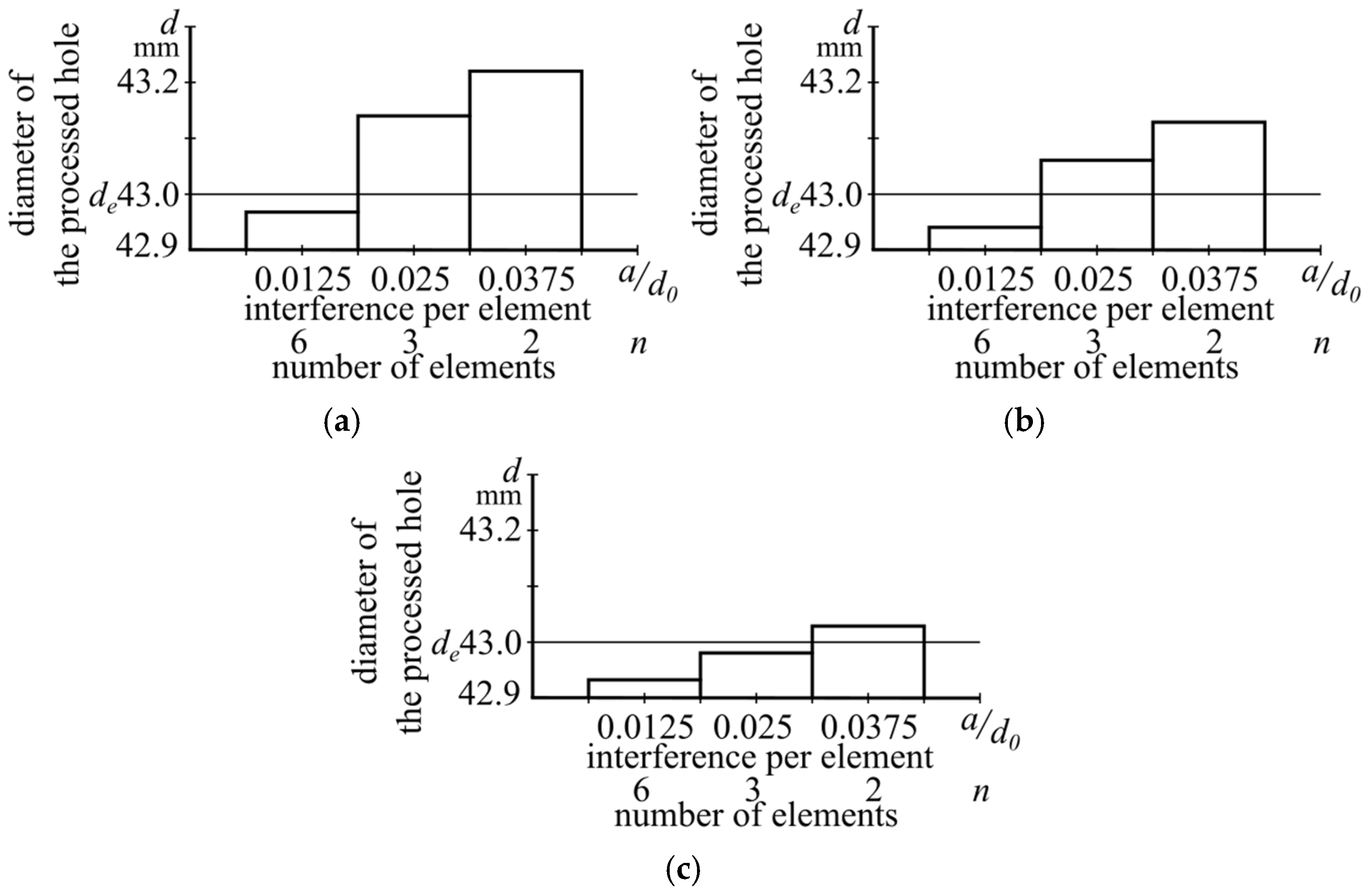
Let us consider the data in
Figure 16, which presents the results of calculating the inner diameter of the processed hole during the simulation of the processing with a total strain
at various workpiece wall thicknesses.
During the processing of a thin-walled workpiece with significant interferences per deforming element (
Figure 16a), hole oversizing occurs; that is, the diameter of the processed hole is larger than the diameter of the deforming element. However, in this case, deforming such a workpiece with an interference
and the same total strain results in hole shrinkage; that is, the diameter of the processed hole is smaller than the diameter of the deforming element. Shrinkage is also observed in almost all cases of processing with a workpiece wall thickness
(
Figure 16c), except for the case where deformation is performed with a significant interference
. In the latter, slight hole oversizing occurs. As for the deformation of a workpiece with a wall thickness
(
Figure 16b), depending on the interference per deforming element, hole shrinkage occurs when using an interference
, while using interferences
and
results in slight hole oversizing. This is explained by the significant influence of the workpiece wall thickness on the height of the non-contact zone. For thin-walled workpieces, during expansion with significant interferences per element, the height of the non-contact zone is substantial and exceeds the value of elastic recovery. As the workpiece wall thickness increases, the height of the non-contact zone decreases proportionally (
Figure 15) and the elastic recovery begins to exceed its value, leading to hole shrinkage.
The presented results establish the conditions for predicting the required hole diameter through the rational selection of broaching modes and workpiece wall thickness.
After determining the number of deforming elements and their interference values and taking into account the significant influence of the number of deforming elements on the level of accumulated strain [
47], a check of the resource of used plasticity on the inner surface of the formed hole is performed. After refining the number of elements and interference values, the appropriate deformation scheme is selected. Possible options include compression, tension, or deformation schemes with a change in the supporting end face [
16].
The obtained results provided the opportunity to manage the process of plastic forming for both the outer and inner surfaces of the workpiece. Next, we will consider the issue of obtaining a specified axial dimension for the deformed workpiece.
As follows from the data in
Table 4,
Table 5 and
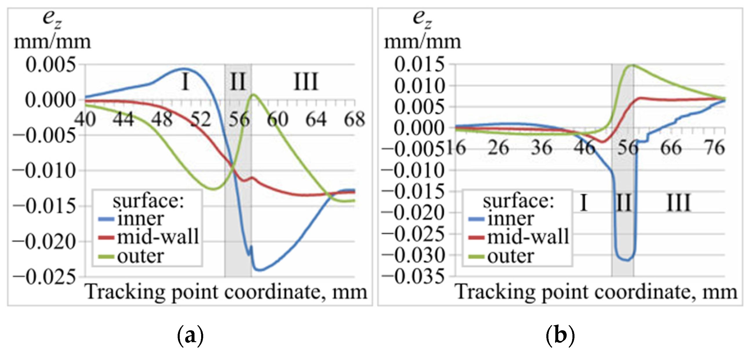
Table 6, the change in the deformed state is significantly influenced by the workpiece wall thickness, the geometric parameters of the tool, and the interference per element. This is confirmed by the results of numerical simulation of the deformation process of a 12ChN3A steel workpiece when determining its axial dimensions for thin-walled (
Figure 17a) and thick-walled (
Figure 17b) workpieces.
In order to establish the influence of the deforming element angle,
, on the axial component of the strain tensor, simulation of the process was performed over a wide range of workpiece wall thicknesses; interferences per element; and values of the angle,
.
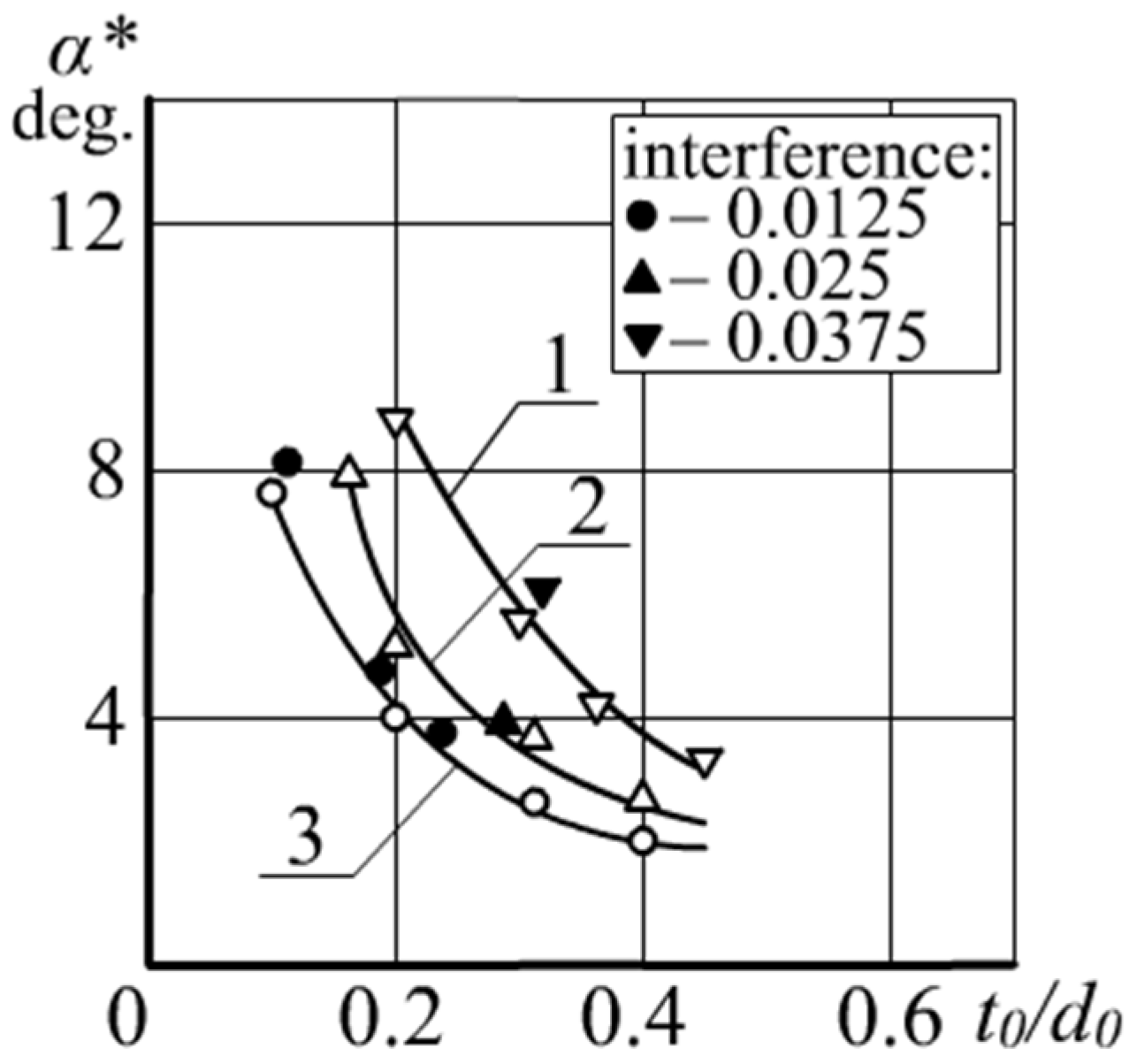
Figure 18 shows the values of the angle,
, at which the absence of axial deformations of the workpiece is ensured for various combinations of wall thickness and interference.
To compare the calculated results with the experimental ones, the experimental data obtained by the visioplasticity method are plotted as markers on the curves (
Figure 18) obtained through computer simulation.
Processing and approximation of the results presented in
Figure 18 made it possible to obtain an analytical relationship for determining the angle,
, which guarantees the absence of axial deformation depending on the workpiece wall thickness and the value of the interference per element:
After obtaining relationships (7), (8), (10), (13), and (14)–(17), which allow calculation of the values of the inner diameter, outer diameter, and axial dimension of the workpiece, we present the control scheme for the plastic forming of workpieces processed by DBR. For workpieces with a given wall thickness, the plastic forming process is managed in the following sequence:
In the first stage, the value of the circumferential strain required to provide the allowance for manufacturing a new part or to compensate for wear and provide the allowance for further machining to restore a worn part is determined;
Next, using relationship (7) obtained through numerical simulation, the required total interference per element, , is determined by Equation (8);
If the part undergoes thermal or thermochemical treatment during processing, a check of the resource of used plasticity on the outer surface of the new or restored part must be performed according to the recommendations in [
47];
In the next stage, according to relationship (10) and taking into account relationships (13)–(16), the diameter of the processed hole is calculated, followed by a check of the resource of used plasticity on its inner surface according to the recommendations in [
47];
Then, based on the given workpiece wall thickness and the determined interference value that ensures the required outer diameter, the angle, , at which axial deformations are absent (i.e., ) is determined using relationship (17);
Subsequently, depending on the operational requirements of the part, conditions are implemented under which the workpiece elongates (), shortens (), or maintains a constant axial dimension ().
The developed scheme for forming the technological process of processing or restoring hollow axisymmetric parts using plastic deformation can be used when designing technological processes for manufacturing new or restoring worn parts.
Elements of the presented scheme can be used during the roughing deformation of tube workpieces according to DSTU EN 10216-1:2019 [
71] standards, the processing of which by DBR ensures obtaining a part with a minimum allowance for subsequent machining.
In the discussion, it should be noted that the presented manuscript is a continuation and development of the authors’ previous publications [
46,
47]; however, it has a different main objective and a different set of practical results. In [
46], the authors refined the scheme of the deformation zone, and in [
47] the key evaluation criterion was the resource of used plasticity and the associated conditions for defect-free forming. In the presented material, the central result is the prediction and technological assurance of the dimensional forming of the workpiece after deforming broaching, primarily the diameter of the processed hole and the axial dimension of the workpiece. For this purpose, a real scheme of the deformation zone and the results of numerical simulation were used to determine the key factor influencing the axial strain of the workpiece. Based on the simulation results, the method for determining the hole diameter was refined, taking into account the real course of strains in the contact and non-contact zones. Additionally, the paper formulates and approximates the dependencies of the hole elastic recovery, which are necessary for the correct prediction of the final hole dimensions. The criterion of the resource of used plasticity, which was the main result of the study in [
47], is applied in this manuscript as an evaluation of the constraint on the suitability of the obtained broaching modes and tool geometry.
As for the definition of critical contact pressure, Rosenberg A.M. and Rosenberg O.A. introduced this concept in [
17], when considering the experimentally obtained dependency
, where
is the length of the contact area, which exhibited an extreme character. The authors explain its extreme character by the presence of critical contact pressure, which causes the processed material to flow out from the contact area into the non-contact zone ahead of it. The authors of that work also present the experimental dependency
, where
is the height of the non-contact zone behind the contact area, which also has an extreme character. However, the authors do not explain the reasons for the extreme nature of this function. The results of our SSS studies allowed us to detect a high level of negative hydrostatic pressure values in the contact area, which creates opportunities for the material to flow from the contact area into two non-contact zones connected to it and to explain the reasons for the simultaneous appearance of the extreme nature of the dependencies
and
. Moreover, we found that the presence of critical contact pressure is a key factor in influencing the axial dimension of the processed workpiece. This was used to determine the technological factors—namely, the interference per element; the workpiece wall thickness; and the angle,
—that affect its achievement. In turn, this enabled the management of the workpiece’s axial dimensions.
It follows from the above materials that the management of the plastic forming scheme is one of the key factors in the development of technological processes for manufacturing both new and restored worn machine parts using deforming broaching. This approach provides the ability to predict and purposefully obtain specified geometric dimensions of parts after plastic deformation. In the presented work, an applied methodology for the technological management of the plastic forming of tubular cylindrical workpieces during deforming broaching is proposed and verified. The methodology is focused on predicting and managing axial deformation, changes in the inner diameter, and its elastic recovery after the passage of the deforming tool. The novelty of the approach lies in the systematic combination of numerical simulation of the stress–strain state within the workpiece deformation zone and its experimental verification by comparing calculated values with experimental data. On this basis, engineering recommendations have been developed for selecting the necessary technological operating parameters and the geometry of the deforming tool.
Based on the performed research, a technological process was developed for manufacturing a “bushing” type part used in the rod joints of the rear boom hydraulic cylinder of JCB backhoe loader models (J.C. Bamford Excavators Ltd., Rocester, UK). The bushing had the following overall dimensions: inner diameter—50 mm, outer diameter—60 mm, length—30 mm. The main critical working surfaces are the inner cylindrical surface of the hole and the outer seating surface of the bushing.
The implementation of this technological process allows for reducing metal consumption by up to 30% for workpiece manufacturing due to replacing the pipe workpiece with dimensions of 63.5 × 9 (DSTU EN 10216-1:2019) [
71], which was processed by cutting in the existing technological process, with a pipe workpiece with dimensions of 60.3 × 6.3 (DSTU EN 10216-1:2019) in the new technological process using DBR. The weight of one meter of the old pipe workpiece is 12.1 kg, while that of the new one is 8.3 kg. In addition, the manufacturing cost of this part is reduced due to savings on the consumption of carbide cutting tools for boring the hole, considering the immense tool life (over 10 km) of carbide deforming elements [
51]. The relevance of improving the mechanical performance, wear resistance, and service life of mining equipment components is also confirmed by recent studies on dissipative steels, hardfacing alloys, TiN-based coatings, and stress–strain analysis of reinforced engineering systems [
72,
73,
74,
75].
The creation of new designs for deforming elements made of superhard composite materials [
76,
77,
78,
79,
80], the use of effective designs of combined (deforming–cutting) broaches [
51], and the application of effective plant-based cooling media that improve the environmental friendliness of the process represent a significant reserve for enhancing its efficiency [
51].




 ,
,