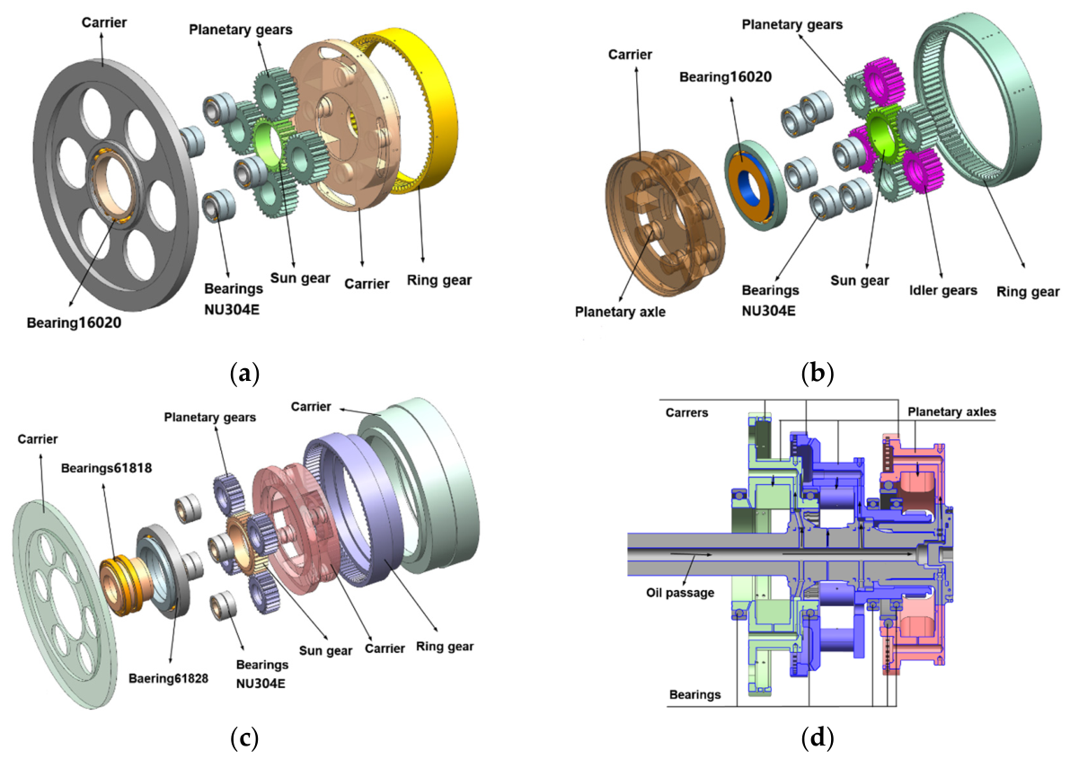
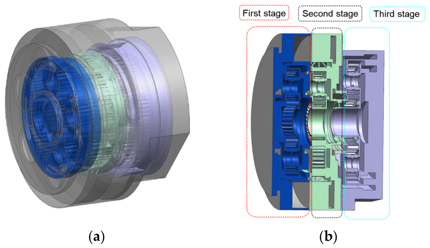
Figure 1.
Oil supply passage and simplified model of the three-stage planetary gear sets ((a) the first-stage planetary gear set; (b) the second-stage planetary gear set; (c) the third-stage planetary gear set; (d) planetary carriers and oil supply passage).
Figure 1.
Oil supply passage and simplified model of the three-stage planetary gear sets ((a) the first-stage planetary gear set; (b) the second-stage planetary gear set; (c) the third-stage planetary gear set; (d) planetary carriers and oil supply passage).
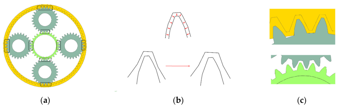
Figure 2.
Gear meshing clearance control ((a) planetary gear set model; (b) tooth surface shifting method; (c) meshing tooth surfaces).
Figure 2.
Gear meshing clearance control ((a) planetary gear set model; (b) tooth surface shifting method; (c) meshing tooth surfaces).
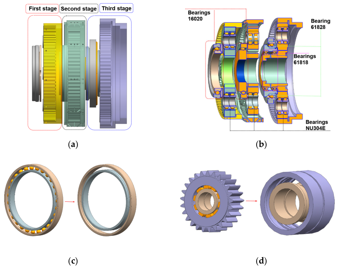
Figure 3.
Bearing locations and model simplification of the multi-stage planetary transmission system ((a) three-stage planetary gear set model; (b) cross-section of the model; (c) simplification of planetary carrier bearings; (d) simplification of planetary gear bearings).
Figure 3.
Bearing locations and model simplification of the multi-stage planetary transmission system ((a) three-stage planetary gear set model; (b) cross-section of the model; (c) simplification of planetary carrier bearings; (d) simplification of planetary gear bearings).
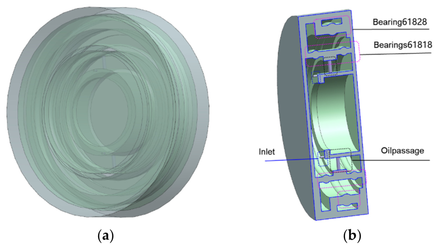
Figure 4.
Fluid domain extracted from a three-stage planetary transmission system. ((a) Overall fluid model; (b) cross-section fluid model).
Figure 4.
Fluid domain extracted from a three-stage planetary transmission system. ((a) Overall fluid model; (b) cross-section fluid model).
Figure 5.
Bearing fluid domain model. ((a) Overall fluid model; (b) cross-section fluid model).
Figure 5.
Bearing fluid domain model. ((a) Overall fluid model; (b) cross-section fluid model).
Figure 6.
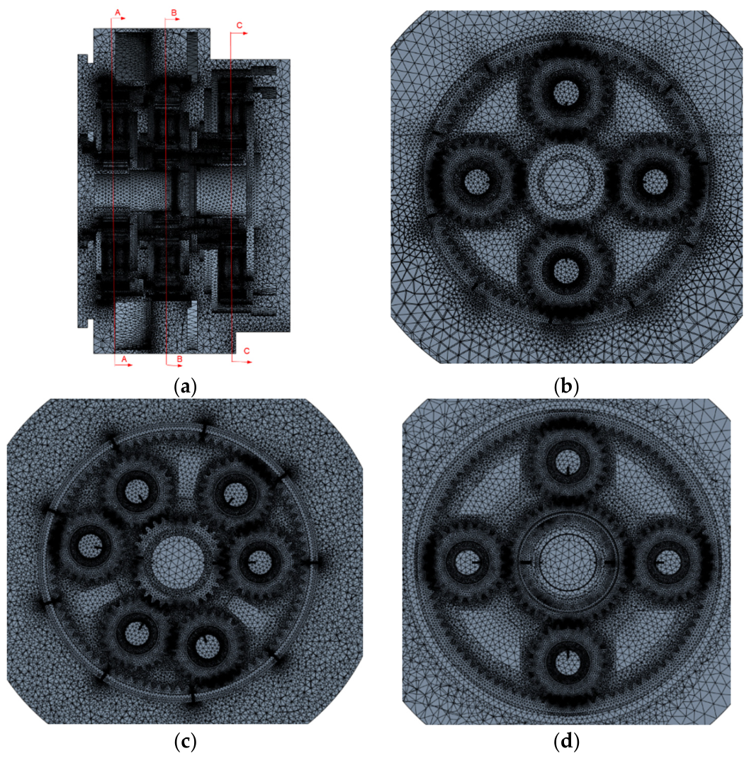
Fluid mesh of the multi-stage planetary transmission system. ((a) Overall mesh model; (b) section A-A; (c) s section B-B; (d) section C-C).
Figure 6.
Fluid mesh of the multi-stage planetary transmission system. ((a) Overall mesh model; (b) section A-A; (c) s section B-B; (d) section C-C).
Figure 7.
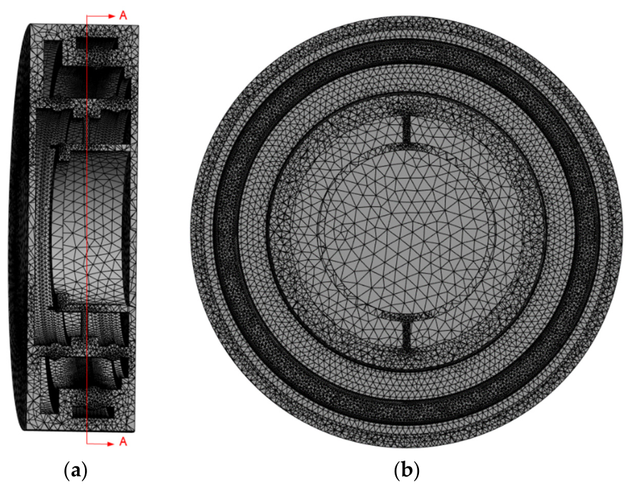
Bearing fluid domain mesh. ((a) Overall mesh model; (b) section A-A).
Figure 7.
Bearing fluid domain mesh. ((a) Overall mesh model; (b) section A-A).
Figure 8.
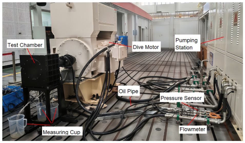
Test bench of the three-stage planetary system.
Figure 8.
Test bench of the three-stage planetary system.
Figure 9.
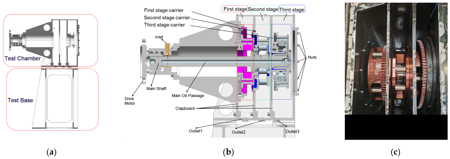
Three stage planetary gearbox for experiments. ((a) Experimental test chamber; (b) test chamber layout diagram; (c) internal assembly).
Figure 9.
Three stage planetary gearbox for experiments. ((a) Experimental test chamber; (b) test chamber layout diagram; (c) internal assembly).
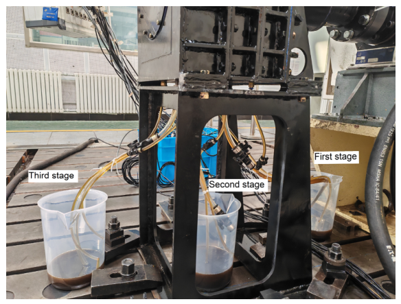
Figure 10.
Oil collection cups for the three-stage planetary gear sets.
Figure 10.
Oil collection cups for the three-stage planetary gear sets.
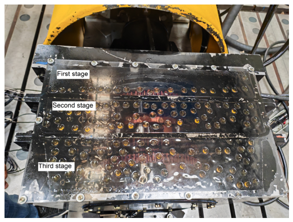
Figure 11.
Oil-splash behavior on the transparent top cover.
Figure 11.
Oil-splash behavior on the transparent top cover.
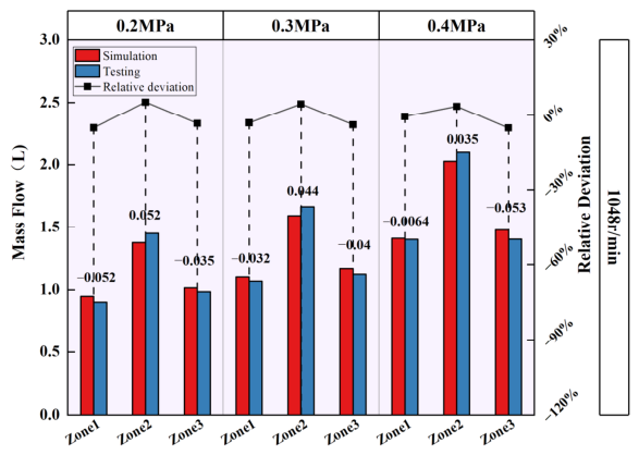
Figure 12.
Comparison of oil discharge volume obtained tests and simulations.
Figure 12.
Comparison of oil discharge volume obtained tests and simulations.
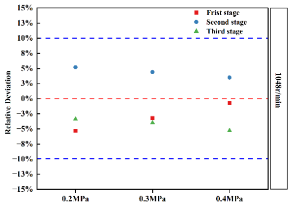
Figure 13.
Relative deviations of oil discharge volume obtained tests and simulations.
Figure 13.
Relative deviations of oil discharge volume obtained tests and simulations.
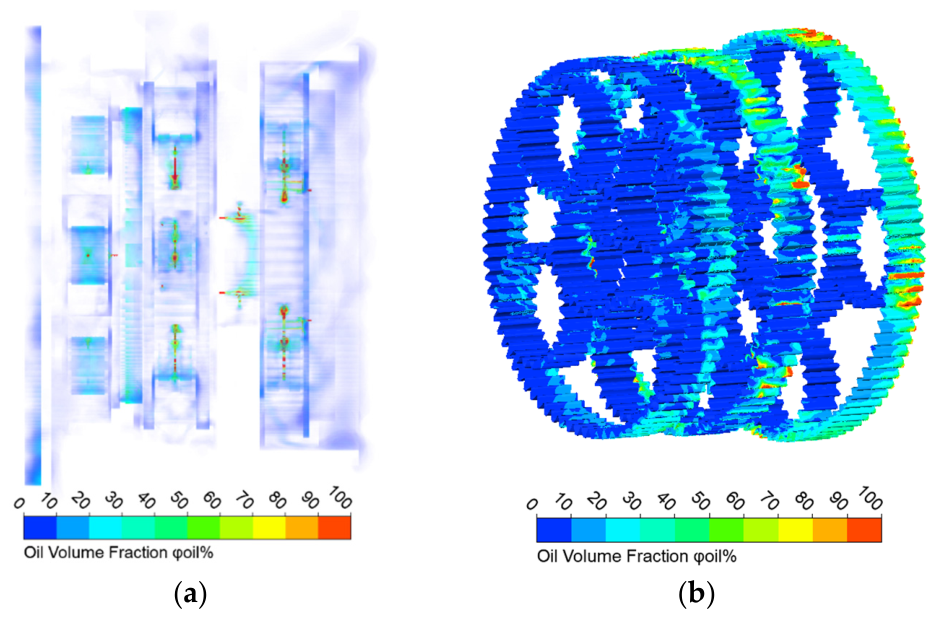
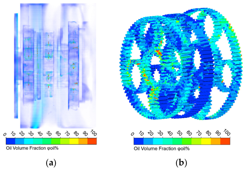
Figure 14.
Oil distribution of the three-stage planetary transmission system. ((a) Overall oil distribution; (b) oil distribution of gears and ring gears).
Figure 14.
Oil distribution of the three-stage planetary transmission system. ((a) Overall oil distribution; (b) oil distribution of gears and ring gears).
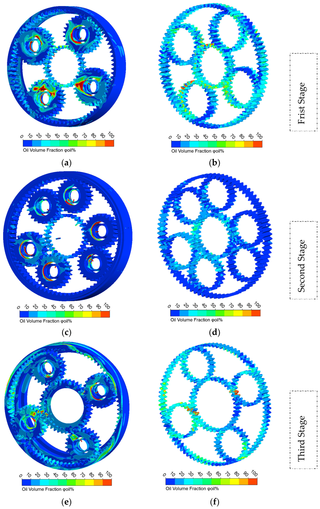
Figure 15.
Oil distribution in each planetary stage under first gear condition. ((a) Overall oil distribution in the first planetary stage; (b) oil distribution in the gears and ring gear of the first planetary stage; (c) overall oil distribution in the second planetary stage; (d) oil distribution in the gears and ring gear of the second planetary stage; (e) overall oil distribution in the third planetary stage; (f) oil distribution in the gears and ring gear of the third planetary stage).
Figure 15.
Oil distribution in each planetary stage under first gear condition. ((a) Overall oil distribution in the first planetary stage; (b) oil distribution in the gears and ring gear of the first planetary stage; (c) overall oil distribution in the second planetary stage; (d) oil distribution in the gears and ring gear of the second planetary stage; (e) overall oil distribution in the third planetary stage; (f) oil distribution in the gears and ring gear of the third planetary stage).
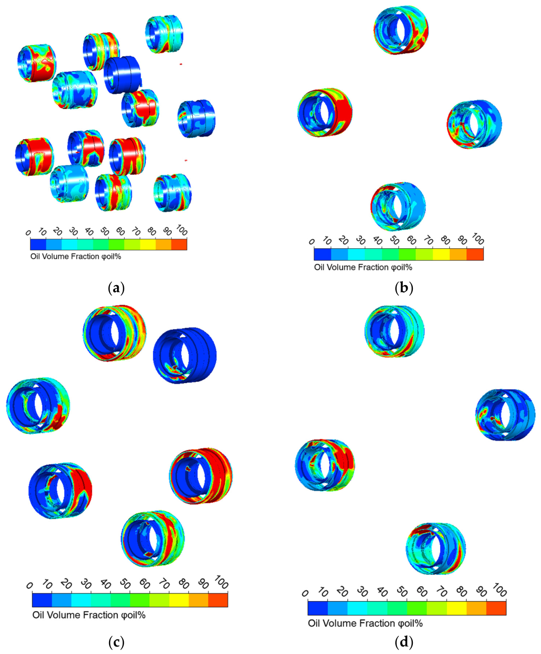
Figure 16.
Oil distribution of NU304E bearings in the multi-stage planetary transmission system under first gear condition. ((a) Oil distribution in planetary gear bearings of all planetary stages; (b) oil distribution in planetary gear bearings of the first planetary stage; (c) oil distribution in planetary gear bearings of the second planetary stage; (d) oil distribution in planetary gear bearings of the third planetary stage).
Figure 16.
Oil distribution of NU304E bearings in the multi-stage planetary transmission system under first gear condition. ((a) Oil distribution in planetary gear bearings of all planetary stages; (b) oil distribution in planetary gear bearings of the first planetary stage; (c) oil distribution in planetary gear bearings of the second planetary stage; (d) oil distribution in planetary gear bearings of the third planetary stage).
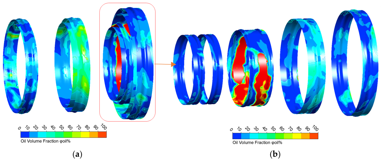
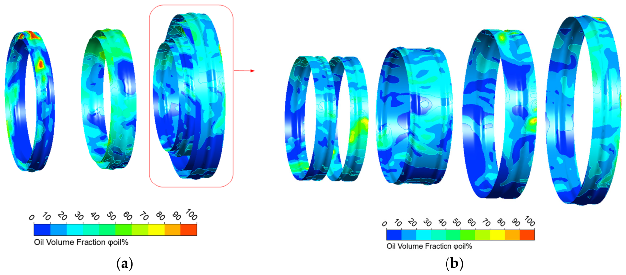
Figure 17.
Oil distribution in deep-groove ball bearings of multi-stage planetary carriers under first gear condition. ((a) Oil distribution in support bearings of three-stage planetary carriers; (b) oil distribution in support bearings of the third-stage planetary carrier).
Figure 17.
Oil distribution in deep-groove ball bearings of multi-stage planetary carriers under first gear condition. ((a) Oil distribution in support bearings of three-stage planetary carriers; (b) oil distribution in support bearings of the third-stage planetary carrier).
Figure 18.
Oil distribution in the multi-stage planetary transmission system. ((a) Overall oil distribution; (b) oil distribution of gears and ring gears).
Figure 18.
Oil distribution in the multi-stage planetary transmission system. ((a) Overall oil distribution; (b) oil distribution of gears and ring gears).
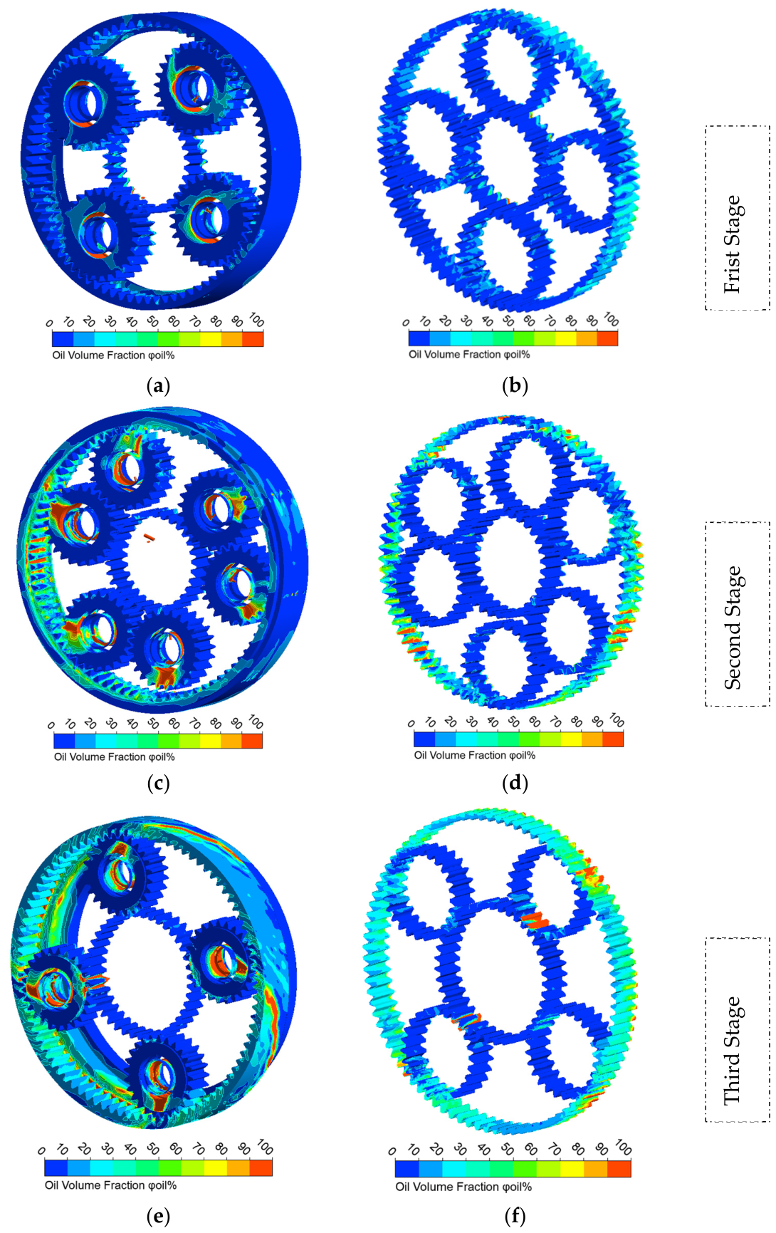
Figure 19.
Oil distribution in each planetary stage under second gear condition. ((a) Overall oil distribution in the first planetary stage; (b) oil distribution in the gears and ring gear of the first planetary stage; (c) overall oil distribution in the second planetary stage; (d) oil distribution in the gears and ring gear of the second planetary stage; (e) overall oil distribution in the third planetary stage; (f) oil distribution in the gears and ring gear of the third planetary stage).
Figure 19.
Oil distribution in each planetary stage under second gear condition. ((a) Overall oil distribution in the first planetary stage; (b) oil distribution in the gears and ring gear of the first planetary stage; (c) overall oil distribution in the second planetary stage; (d) oil distribution in the gears and ring gear of the second planetary stage; (e) overall oil distribution in the third planetary stage; (f) oil distribution in the gears and ring gear of the third planetary stage).
Figure 20.
Oil distribution of NU304E bearings in the multi-stage planetary transmission system under second gear condition. ((a) Oil distribution in planetary gear bearings of all planetary stages; (b) oil distribution in planetary gear bearings of the first planetary stage; (c) oil distribution in planetary gear bearings of the second planetary stage; (d) oil distribution in planetary gear bearings of the third planetary stage).
Figure 20.
Oil distribution of NU304E bearings in the multi-stage planetary transmission system under second gear condition. ((a) Oil distribution in planetary gear bearings of all planetary stages; (b) oil distribution in planetary gear bearings of the first planetary stage; (c) oil distribution in planetary gear bearings of the second planetary stage; (d) oil distribution in planetary gear bearings of the third planetary stage).
Figure 21.
Oil distribution in deep-groove ball bearings of multi-stage planetary carriers under second gear condition. ((a) Oil distribution in support bearings of three-stage planetary carriers; (b) oil distribution in support bearings of the third-stage planetary carrier).
Figure 21.
Oil distribution in deep-groove ball bearings of multi-stage planetary carriers under second gear condition. ((a) Oil distribution in support bearings of three-stage planetary carriers; (b) oil distribution in support bearings of the third-stage planetary carrier).
Figure 22.
Bearing structural model. ((a) Bearing cross-section and model description; (b) overall fluid domain model of the bearing structure).
Figure 22.
Bearing structural model. ((a) Bearing cross-section and model description; (b) overall fluid domain model of the bearing structure).
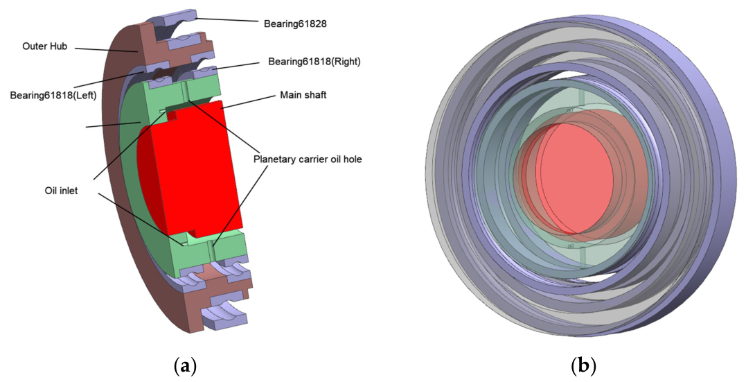
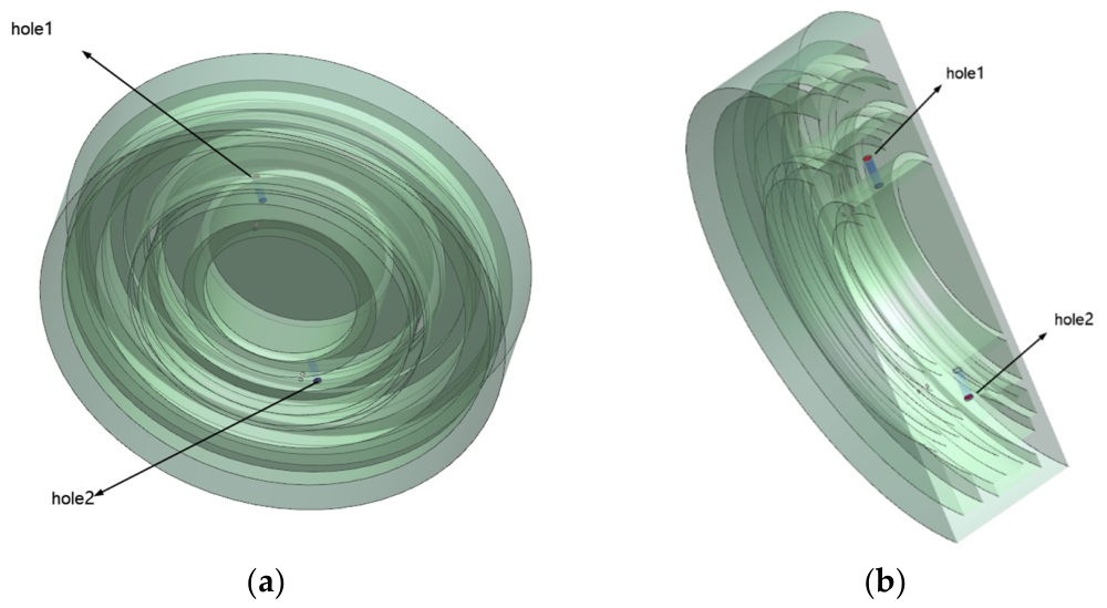
Figure 23.
Location of the monitoring surfaces. ((a) Full model with detection surfaces; (b) cross-section of the model).
Figure 23.
Location of the monitoring surfaces. ((a) Full model with detection surfaces; (b) cross-section of the model).
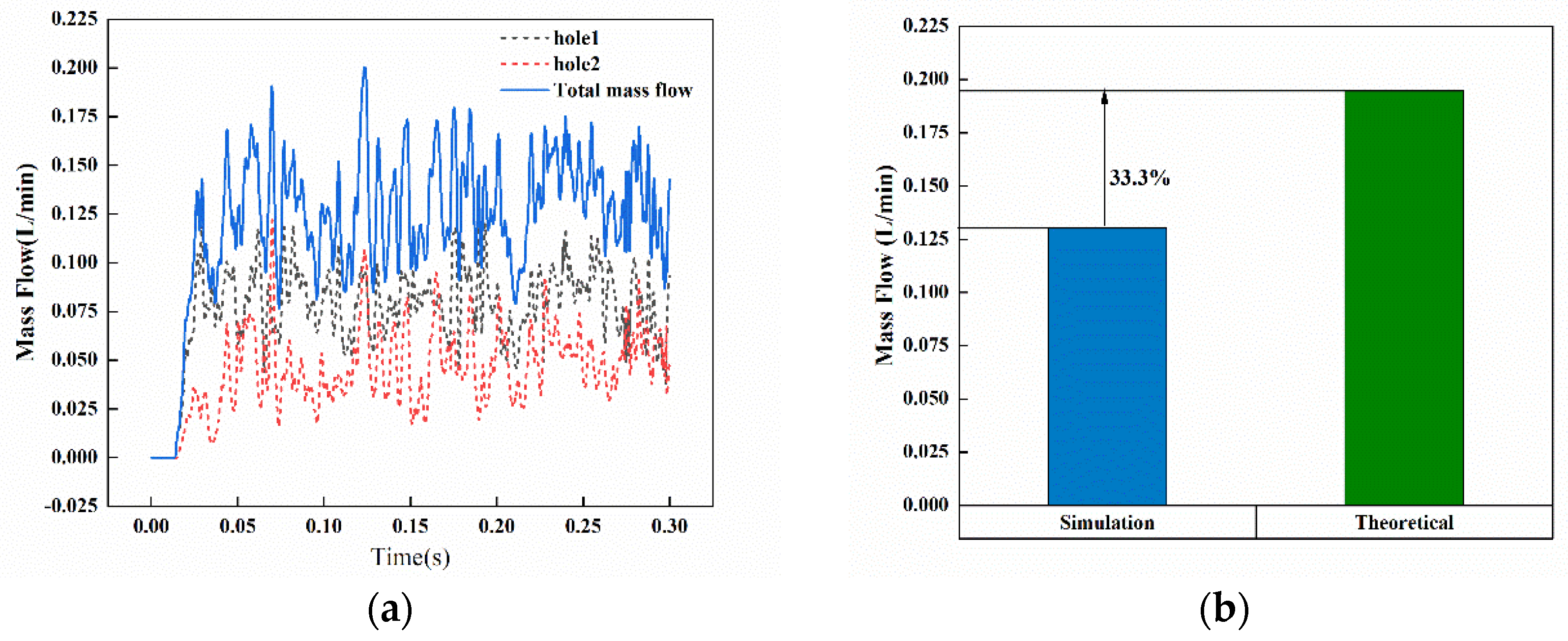
Figure 24.
Flow rate variation and data comparison at monitoring surfaces. ((a) Flow rate variation curves at monitoring surfaces; (b) deviation of flow rate data).
Figure 24.
Flow rate variation and data comparison at monitoring surfaces. ((a) Flow rate variation curves at monitoring surfaces; (b) deviation of flow rate data).
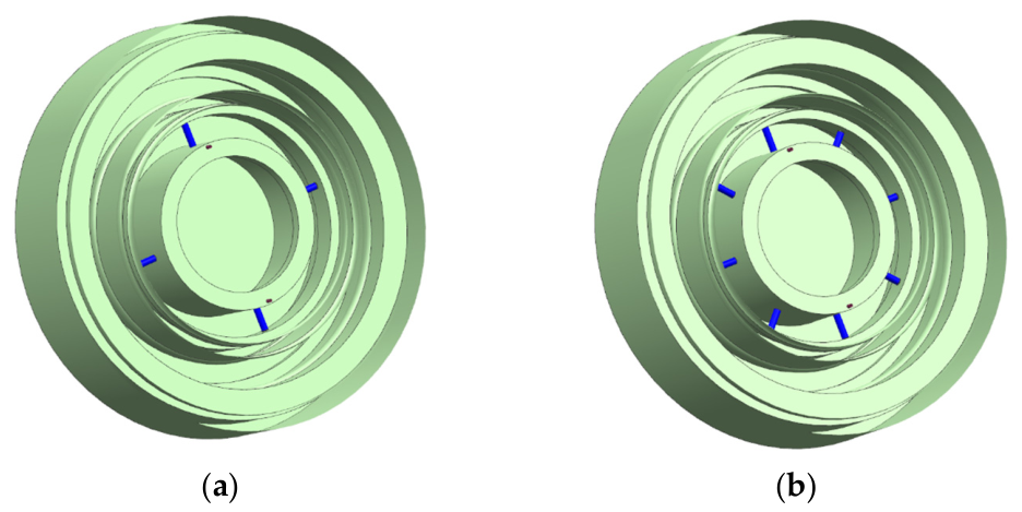
Figure 25.
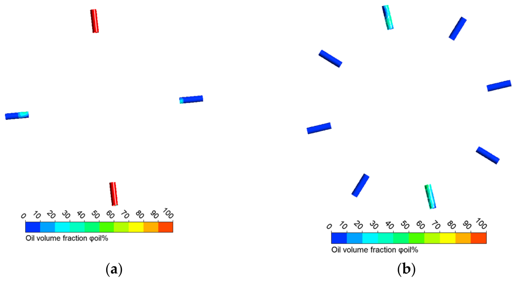
Fluid domain with different numbers of oil holes. ((a) Fluid domain with four oil holes; (b) fluid domain with eight oil holes).
Figure 25.
Fluid domain with different numbers of oil holes. ((a) Fluid domain with four oil holes; (b) fluid domain with eight oil holes).
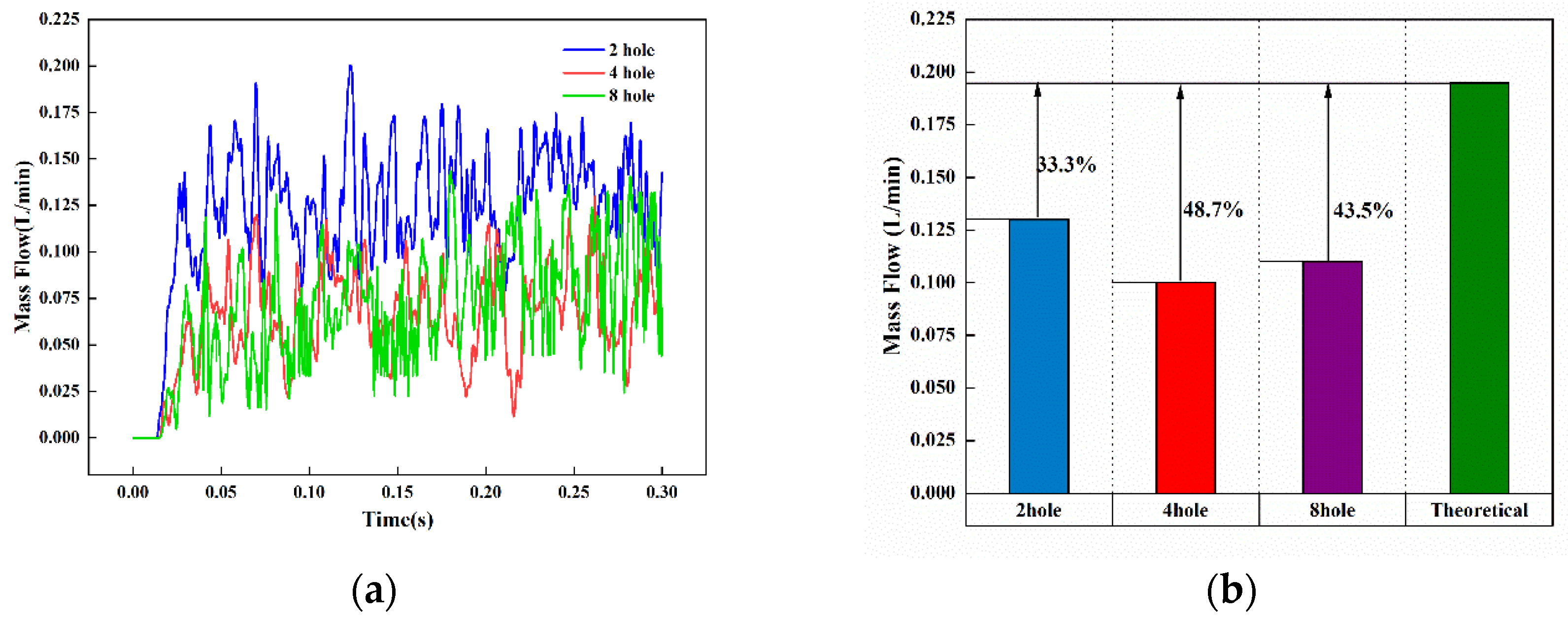
Figure 26.
Flow monitoring and data analysis of structures with different numbers of oil holes. ((a) Flow rate variation curves at monitoring surfaces; (b) deviation of flow rate data).
Figure 26.
Flow monitoring and data analysis of structures with different numbers of oil holes. ((a) Flow rate variation curves at monitoring surfaces; (b) deviation of flow rate data).
Figure 27.
Oil volume fraction distribution contours of oil holes. ((a) Oil volume fraction distribution of the four oil holes; (b) oil volume fraction distribution of the eight oil holes).
Figure 27.
Oil volume fraction distribution contours of oil holes. ((a) Oil volume fraction distribution of the four oil holes; (b) oil volume fraction distribution of the eight oil holes).
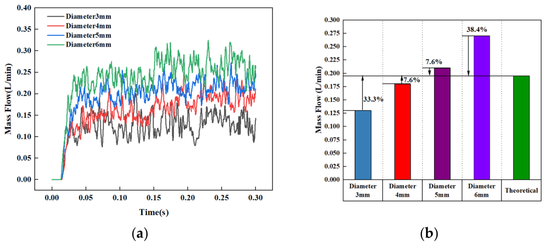
Figure 28.
Flow monitoring and data analysis of structures with different oil hole diameters. ((a) Flow rate variation curves at monitoring surfaces; (b) deviation of flow rate data).
Figure 28.
Flow monitoring and data analysis of structures with different oil hole diameters. ((a) Flow rate variation curves at monitoring surfaces; (b) deviation of flow rate data).
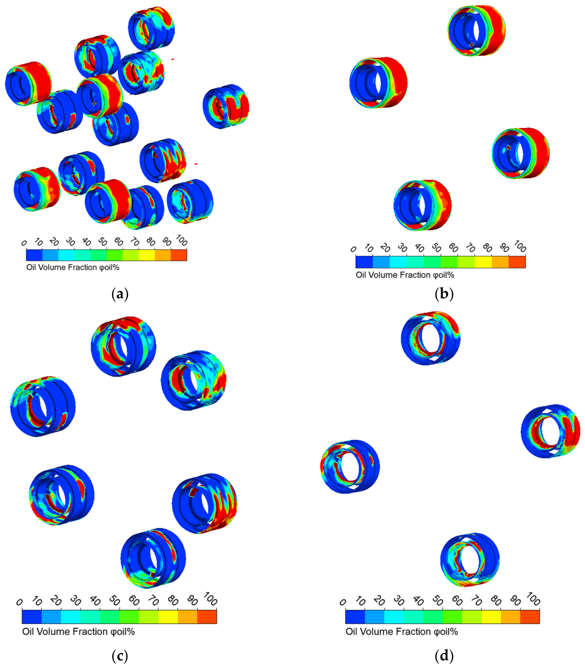
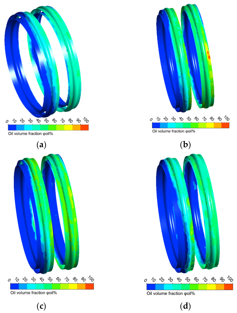
Figure 29.
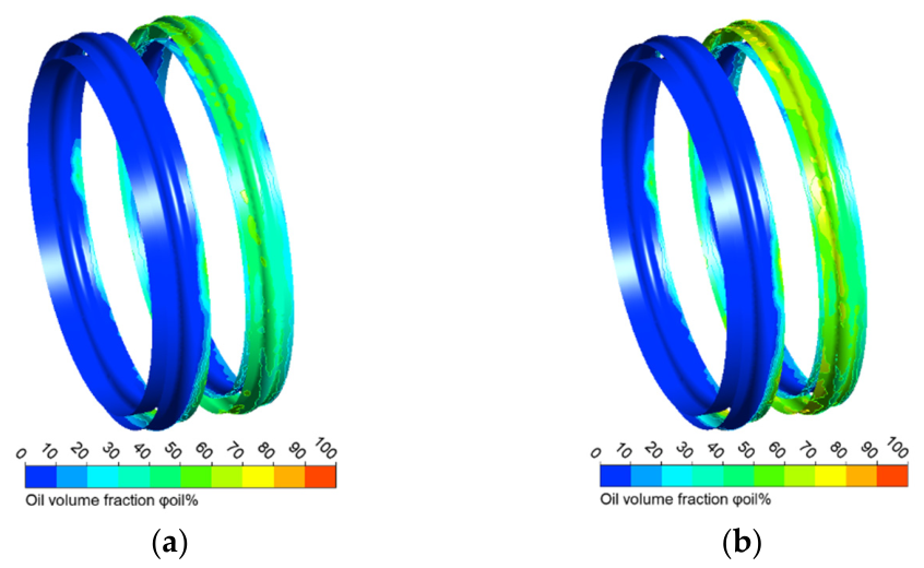
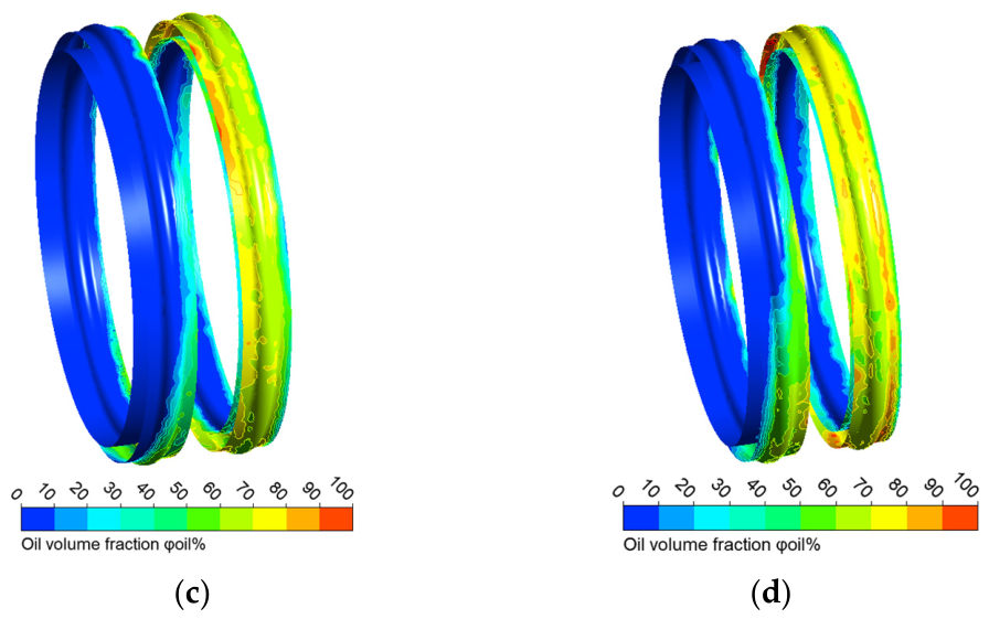
Oil distribution on both bearings. ((a) Oil distribution on bearings with oil hole diameter of 3 mm; (b) oil distribution on bearings with oil hole diameter of 4 mm; (c) oil distribution on bearings with oil hole diameter of 5 mm; (d) oil distribution on bearings with oil hole diameter of 6 mm).
Figure 29.
Oil distribution on both bearings. ((a) Oil distribution on bearings with oil hole diameter of 3 mm; (b) oil distribution on bearings with oil hole diameter of 4 mm; (c) oil distribution on bearings with oil hole diameter of 5 mm; (d) oil distribution on bearings with oil hole diameter of 6 mm).
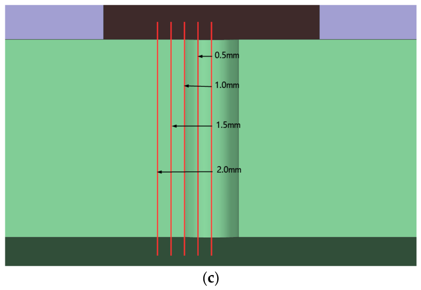
Figure 30.
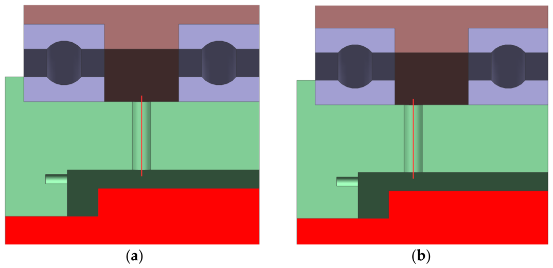
Description of oil hole offset structures. ((a) Original position of the oil hole; (b) offset position of the oil hole; (c) all oil hole offset structures).
Figure 30.
Description of oil hole offset structures. ((a) Original position of the oil hole; (b) offset position of the oil hole; (c) all oil hole offset structures).
Figure 31.
Oil distribution on left and right bearing raceways. ((a) Oil distribution with a 0.5 mm leftward offset; (b) oil distribution with a 1 mm leftward offset; (c) oil distribution with a 1.5 mm leftward offset; (d) oil distribution with a 2 mm leftward offset).
Figure 31.
Oil distribution on left and right bearing raceways. ((a) Oil distribution with a 0.5 mm leftward offset; (b) oil distribution with a 1 mm leftward offset; (c) oil distribution with a 1.5 mm leftward offset; (d) oil distribution with a 2 mm leftward offset).
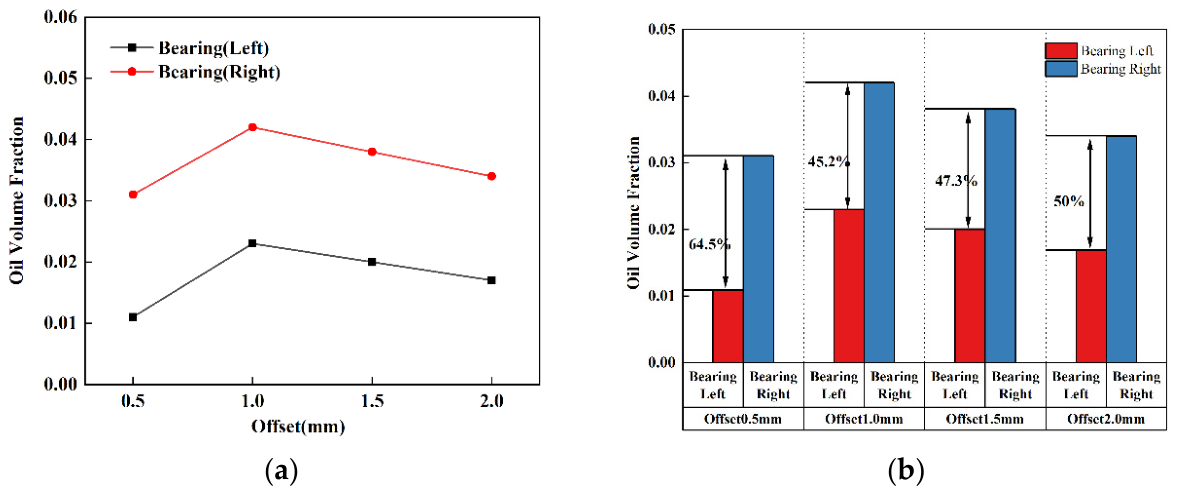
Figure 32.
Average oil volume fraction on bearing surfaces with oil hole offset distance. ((a) Oil volume fraction distribution under different structures; (b) oil volume fraction deviation distribution under different structures).
Figure 32.
Average oil volume fraction on bearing surfaces with oil hole offset distance. ((a) Oil volume fraction distribution under different structures; (b) oil volume fraction deviation distribution under different structures).
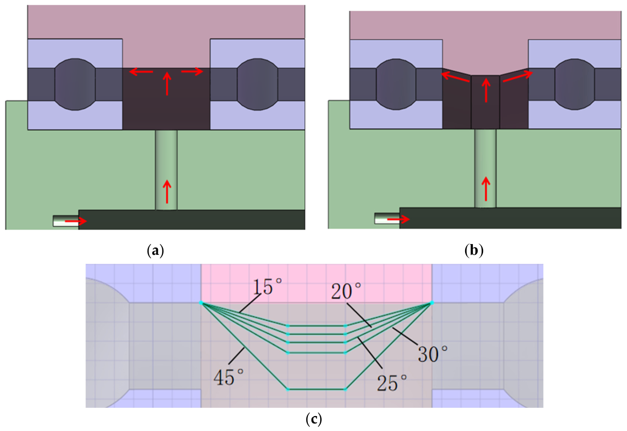
Figure 33.
Outer hub structures with different oil-guiding inclination angles. ((a) Original outer hub structure; (b) outer hub structure with oil-guiding inclination angle; (c) outer hub structures with all oil-guiding inclination angles).
Figure 33.
Outer hub structures with different oil-guiding inclination angles. ((a) Original outer hub structure; (b) outer hub structure with oil-guiding inclination angle; (c) outer hub structures with all oil-guiding inclination angles).
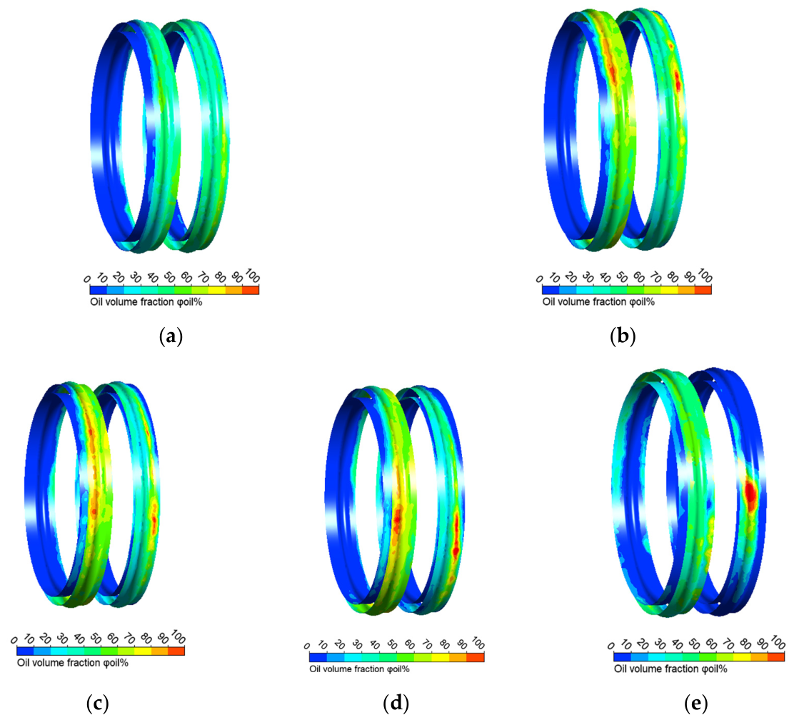
Figure 34.
Oil volume fraction distribution on bearing surfaces under different oil-guiding inclination angles ((a) oil volume fraction distribution under a 15° inclination angle; (b) oil volume fraction distribution under a 20° inclination angle; (c) oil volume fraction distribution under a 25° inclination angle; (d) oil volume fraction distribution under a 30° inclination angle; (e) oil volume fraction distribution under a 45° inclination angle).
Figure 34.
Oil volume fraction distribution on bearing surfaces under different oil-guiding inclination angles ((a) oil volume fraction distribution under a 15° inclination angle; (b) oil volume fraction distribution under a 20° inclination angle; (c) oil volume fraction distribution under a 25° inclination angle; (d) oil volume fraction distribution under a 30° inclination angle; (e) oil volume fraction distribution under a 45° inclination angle).
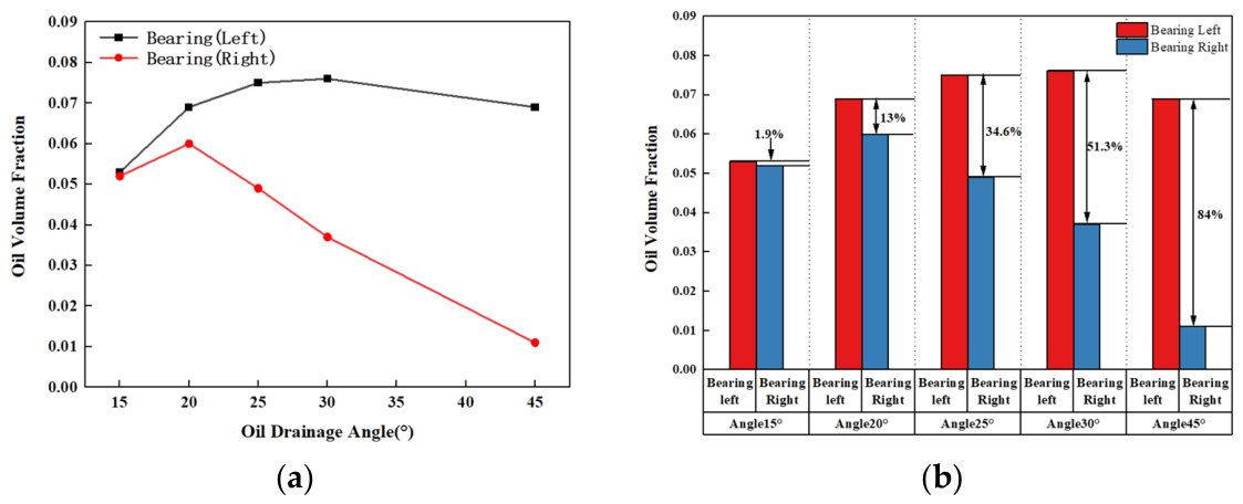
Figure 35.
Average oil volume fraction on bearing surfaces as oil-guiding inclination angle. ((a) Oil volume fraction distribution curves under different oil-guiding inclination angles; (b) deviation of oil volume fraction under different oil-guiding inclination angles).
Figure 35.
Average oil volume fraction on bearing surfaces as oil-guiding inclination angle. ((a) Oil volume fraction distribution curves under different oil-guiding inclination angles; (b) deviation of oil volume fraction under different oil-guiding inclination angles).
Table 1.
Gear parameters in a three-stage planetary transmission system.
Table 1.
Gear parameters in a three-stage planetary transmission system.
| Stages | Components | Number of Teeth/z | Module m/mm | Pressure Angle | Face Width/mm |
|---|
| First stage | Sun gear | 31 | 3 | 20 | 32 |
| Planetary gear | 81 |
| Ring gear | 25 |
| Second stage | Sun gear | 31 | 3 | 20 | 32 |
| Idler gear | 23 |
| Planetary gear | 23 |
| Ring gear | 81 |
| Third stage | Planetary gear | 25 | 3 | 20 | 27 |
| Ring gear | 89 |
| Sun gear | 39 |
Table 2.
Parameters of bearings.
Table 2.
Parameters of bearings.
| Name | Bearing Width/mm | Bearing Bore Diameter/mm | Bearing Outside Diameter/mm |
|---|
| Bearing 16020 | 16 | 100 | 150 |
| Bearing 61818 | 13 | 90 | 115 |
| Bearing 61828 | 18 | 140 | 175 |
| Bearing NU304E | 15 | 20 | 52 |
Table 3.
Rotational speeds of components in the three-stage planetary transmission (first gear condition).
Table 3.
Rotational speeds of components in the three-stage planetary transmission (first gear condition).
| Components | Speed of First Stage (r/min) | Speed of Second Stage (r/min) | Speed of Third Stage (r/min) |
|---|
| Sun gear | 3000 | 573 | 354 |
| Planetary gear | 3009 | 1251 | 0 |
| Ring gear | 354 | 0 | 354 |
| Planetary carrier | 573 | 354 | 354 |
Table 4.
Rotational speeds of components in the three-stage planetary transmission (second gear condition).
Table 4.
Rotational speeds of components in the three-stage planetary transmission (second gear condition).
| Components | Speed of First Stage (r/min) | Speed of Second Stage (r/min) | Speed of Third Stage (r/min) |
|---|
| Sun gear | 3000 | 0 | 1149 |
| Planetary gear | 3720 | 1547 | 0 |
| Ring gear | 1140 | 708 | 1149 |
| Planetary carrier | 0 | 1149 | 1149 |
Table 5.
Physical parameters of simulations.
Table 5.
Physical parameters of simulations.
| Parameter | Value |
|---|
| Input rotational speed n [r/min] | See Table 3 and Table 4 |
| Inlet pressure P1 [MPa] | 0.2 |
| Inlet mass m1 [Kg/s] | 0.207925 |
| Oil density at 25 °C [Kg/m3] | 870 |
| Air density at 25 °C [Kg/m3] | 1.128 |
| Oil dynamic viscosity at 25 °C μ1 [Kg/m·s] | 1.74 × 10⁻¹ |
| Air dynamic viscosity at 25 °C μ2 [Kg/m·s] | 1.907 × 10⁻⁵ |
| Oil specific heat Capacity 25 °C CP [J/kg·°C] | 1870 |
| version of the software | ANSYS Fluent 2022 |
Table 6.
Physical parameters of the validation tests.
Table 6.
Physical parameters of the validation tests.
| Parameter | Value |
|---|
| Input rotational speed n [r/min] | 1048 |
| Inlet pressure P1 [MPa] | 0.2, 0.3, 0.4 |
| Oil density at 25 °C [Kg/m3] | 870 |
| Oil dynamic viscosity at 25 °C μ1 [Kg/m·s] | 1.74 × 10⁻¹ |
| Air density at 25 °C [Kg/m3] | 1.128 |
| Air dynamic viscosity at 25 °C μ2 [Kg/m·s] | 1.907 × 10⁻⁵ |
Table 7.
Grid independence verification.
Table 7.
Grid independence verification.
| Sizes of Mesh | The Number of Mesh | The Flow Rate Deviation |
|---|
| 0.8 [mm] | 3,038,901 | 0.08% |
| 1.2 [mm] | 2,787,983 | 0.11% |
| 1.6 [mm] | 2,440,692 | 0.23% |
Table 8.
Oil flow rates under different numbers of oil holes.
Table 8.
Oil flow rates under different numbers of oil holes.
| Parameters | Scheme 1 | Scheme 2 | Scheme 3 |
|---|
| Number of oil hole | 2 | 4 | 8 |
| Flow rate (L/min) | 0.13 | 0.10 | 0.11 |
Table 9.
Oil flow rates under different diameters of oil hole.
Table 9.
Oil flow rates under different diameters of oil hole.
| Parameters | Scheme 1 | Scheme 2 | Scheme 3 | Scheme 4 |
|---|
| Diameter of oil hole (mm) | 3 | 4 | 5 | 6 |
| Flow rate (L/min) | 0.13 | 0.18 | 0.21 | 0.27 |