Article

Distributed Online Voltage Control with Feedback Delays Under Coupled Constraints for Distribution Networks

1
School of Electronic and Information Engineering, Changsha University of Science & Technology, Changsha 410114, China
2
State Grid Hunan Electric Power Co., Ltd., Power Supply Service Center, Changsha 410114, China
3
State Grid Hunan Electric Power Company Research Institute, Changsha 410007, China
4
Xiangtan Power Supply Company, State Grid Hunan Electric Power Company Limited, Xiangtan 411100, China
*
Author to whom correspondence should be addressed.
Technologies 2025, 13(8), 327; https://doi.org/10.3390/technologies13080327
Submission received: 18 June 2025 / Revised: 18 July 2025 / Accepted: 25 July 2025 / Published: 31 July 2025

Abstract

High penetration of photovoltaic (PV) generation presents new challenges for voltage regulation in distribution networks (DNs), primarily due to output intermittency and constrained reactive power capabilities. This paper introduces a distributed voltage control method leveraging reactive power compensation from PV inverters. Instead of relying on centralized computation, the proposed method allows each inverter to make local decisions using real-time voltage measurements and delayed communication with neighboring PV nodes. To account for practical asynchronous communication and feedback delay, a Distributed Online Primal–Dual Push–Sum (DOPP) algorithm that integrates a fixed-step delay model into the push–sum coordination framework is developed. Through extensive case studies on a modified IEEE 123-bus system, it has been demonstrated that the proposed method maintains robust performance under both static and dynamic scenarios, even in the presence of fixed feedback delays. Specifically, in static scenarios, the proposed strategy rapidly eliminates voltage violations within 50–100 iterations, effectively regulating all nodal voltages into the acceptable range of [0.95, 1.05] p.u. even under feedback delays with a delay step of 10. In dynamic scenarios, the proposed strategy ensures 100% voltage compliance across all nodes, demonstrating superior voltage regulation and reactive power coordination performance over conventional droop and incremental control approaches.

1. Introduction

In recent years, the penetration of PV generation in DNs has increased markedly. The high penetration of renewable energy sources has introduced new technical challenges [1]. The strong intermittency and stochasticity of PV generation have made the operating conditions of DNs increasingly complex, leading to more prominent issues such as voltage fluctuations, voltage exceeding limits, and degradation of power quality [2]. Therefore, how to achieve reactive power optimization and voltage dynamic regulation in DNs with high PV penetration is critical for ensuring the safe, efficient, and stable operation of DNs. At present, a large number of researchers have proposed various reactive power and voltage optimization control methods to address the integration of large-scale distributed generation, achieving significant results. These methods are primarily categorized into two types: centralized and distributed reactive power optimization approaches.
Centralized reactive power optimization methods typically rely on a central control center, which collects data from the entire network and uses optimization algorithms to compute the optimal reactive power distribution. To address voltage fluctuations caused by the integration of distributed generation, researchers have developed various centralized reactive power optimization and control approaches. Reference [3] introduces a convex relaxation-based centralized optimal power flow method using the branch flow model, offering a theoretical foundation for implementing Volt–var control in DNs. In reference [4], comparative studies validated the effectiveness of centralized Volt–var control in maintaining voltage stability and meeting relevant constraints. A linear programming method based on sensitivity coefficients was proposed in [5], enabling rapid real-time dispatch without the need for specific network parameters. Additionally, genetic algorithms, HGPSO, and MPC have been widely applied to centralized reactive power optimization [6,7,8,9]. For instance, to achieve multi-objective coordinated control, fuzzy sets and genetic algorithms were introduced in [10] to design a centralized reactive power optimization model that simultaneously accounts for voltage deviation, power loss, and compensation costs, demonstrating strong adaptability and convergence performance. However, while centralized reactive power optimization methods are capable of achieving the global optimum, they require the continuous collection of measurement data from the entire network to perform centralized calculations. This leads to a significant reliance on communication infrastructure, with high demands for communication bandwidth, delay tolerance, and data integrity [11]. In situations where communication quality is unstable or faults arise, the real-time performance and execution effectiveness of control strategies can be severely impacted. Moreover, as DNs grow in scale, the number of nodes and their state dimensions increase, causing a sharp rise in computational complexity for centralized approaches. Particularly when tackling non-convex optimal power flow problems in dynamic environments, these methods face challenges in adapting to scenarios characterized by high-frequency changes [12,13]. Therefore, the limitations of centralized approaches are particularly evident in rural distribution networks with high PV penetration, such as those in China. These systems often suffer from weak communication infrastructure, complex topologies, and frequent voltage fluctuations caused by intermittent PV output. To address the shortcomings of the centralized control, distributed reactive power optimization control methods have gradually become a research hotspot. Recent studies highlight the practical value of distributed coordination in such contexts. For instance, in Thailand’s Mae Sa Riang microgrid, distributed BESS optimization reduced voltage deviation by 46% using only local data and neighbor communication [14]. Meanwhile, in European energy communities, day-ahead optimization incorporating distributed PV, storage, and flexible loads has shown potential for improving cost-effectiveness and adaptability to local demand patterns [15]. These cases confirm that distributed strategies effectively resolve voltage violations and operational challenges in PV-dense networks with constrained communication, which is critical for energy communities, rural grids, and non-interconnected island systems.
These methods no longer rely on a central controller for the unified collection and centralized computation of entire network information. Instead, reactive power control decisions are made through multi-agent collaboration, with each node relying solely on local measurement data and limited communication with neighboring PV nodes. This ensures power quality while improving the scalability and control robustness of DNs [16]. Various typical distributed reactive power control strategies have been proposed to date, one of which is the traditional droop control advocated by the IEEE 1547-2018 standard [17,18,19]. It is a static feedback method based on local voltage measurements, where the local bus voltage is monitored and reactive power injection is adjusted accordingly. However, ref. [20] shows that under certain conditions, droop controllers may fail to maintain a feasible voltage distribution. Since these static feedback rules can lead to oscillatory behavior, incremental control strategies have been proposed. This class of methods introduces historical reactive power set-point feedback based on traditional static control. Nodes adjust power injection according to voltage magnitude and past reactive power set-points [21,22]. In addition, new methods based on distributed primal–dual algorithms and push–sum algorithms have been proposed [23,24,25]. For example, ref. [25] investigates the general constraints of distributed online optimization, specifically coupled inequality constraints. A distributed primal–dual algorithm for online optimization was proposed, and it was proven that this method can achieve sublinear static regret, which indicates the algorithm’s capability of maintaining long-term optimization performance and gradually converging to near-optimal solutions. However, most existing distributed online voltage control methods fail to adequately account for real-world operating conditions in DNs, such as severe voltage fluctuations and the stochastic fluctuations of loads and distributed generation. Additionally, they neglect comprehensive research on voltage quality optimization.
In practical applications such as federated learning and wireless sensor networks, terminal devices are often subject to delays when executing computational tasks and transmitting data over networks [26]. These factors collectively induce information delays. Thus, extensive literature has thoroughly investigated the impact of information delays on the performance of various optimization algorithms [27,28,29,30,31,32,33,34]. For example, ref. [27] explores the feasibility of employing a dual averaging algorithm and mirror descent algorithm to handle delayed information in the context of distributed delayed stochastic optimization. In [28], a distributed mirror descent algorithm with subgradient delay is presented for distributed convex optimization. The effect of delays to the consensus algorithm over a distributed system of agents having time-varying network graphs is studied in [30]. Meanwhile, the feedback delay apparently existed in online optimization as well. To address unattainable real-time feedback, ref. [31] proposes the online optimization algorithm utilizing delayed feedback information. Asynchronous online learning with nonlinear network constraints in multi-agent systems is explored in [32,33], wherein primal and dual variables are updated via delayed gradient information, respectively.
To address the aforementioned issues, this paper proposes a distributed online reactive power–voltage optimization control method for voltage regulation in DNs. Building on this foundation, distributed online optimization problems with time-varying constraints are further investigated. To align with practical communication environments where state feedback suffers from delays, a delayed feedback mechanism is introduced. Specifically, during each decision-making round, each node cannot immediately access accurate feedback from its current neighboring PV nodes but only receives time-lagged historical information. The paper focuses on analyzing the impact of delayed feedback on the performance and robustness of the proposed DOPP algorithm under asynchronous communications and limited feedback conditions.
Specifically, this paper first formulates an optimization model that aims to minimize voltage deviation in DNs. The model is subject to the upper and lower limits of node voltages and the reactive power output limits of distributed PV inverters. To overcome the challenges of high communication volume and computational burden associated with traditional centralized solving approaches, a DOPP method is introduced. This method coordinates limited neighbor-to-neighbor communication, incorporating a push–sum strategy to enable rapid consensus and global convergence of Lagrange multipliers under unbalanced grid topologies. Each PV inverter node can independently and concurrently update its reactive power decisions online using only local measurements and neighbor communication data, significantly reducing both communication overhead and computational complexity at individual nodes. At the same time, the method enables real-time tracking of load and PV output fluctuations, dynamically optimizing voltage levels and line losses. Particularly, with the integration of a delayed feedback mechanism, the DOPP method maintains effective and stable reactive power control even when each PV node operates under realistic communication conditions where only delayed feedback from local measurements and neighbors is available. This demonstrates enhanced robustness to delays and excellent dynamic adaptability.
To better illustrate the novelty of our method in comparison with related approaches, Table 1 provides a structured comparison of representative algorithms, focusing on five dimensions: voltage constraint handling, reactive power constraint consideration, communication requirements, delay treatment, and handling of feedback delays. Unlike existing methods, the proposed strategy jointly considers strict voltage and reactive power limits, fixed feedback delays, and realistic unbalanced communication, which enhances its adaptability and robustness under practical distribution network conditions.

2. Distributed Voltage Control Framework Based on DOPP Algorithm with Feedback Delays

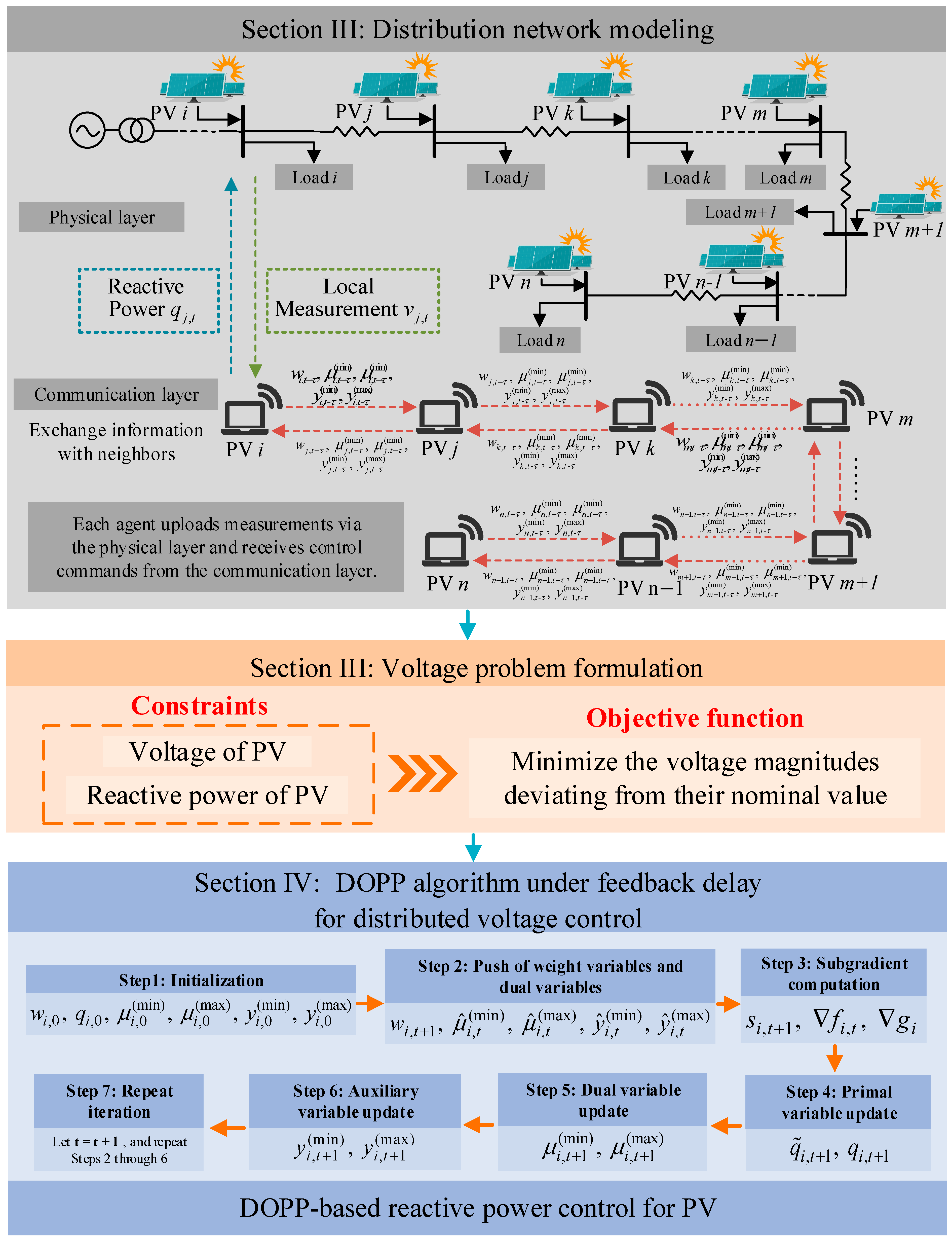
Figure 1 illustrates the overall framework of the proposed distributed voltage control strategy for distribution networks with high PV penetration. The framework integrates physical-layer modeling of the power system with a communication layer structure based on local information exchange. In particular, the communication layer only allows data exchange between neighboring PV nodes that are directly connected without any intermediate PV nodes. This framework reflects the overall approach and idea of this study, which aims to develop a distributed optimization and control strategy that explicitly accounts for communication delays and local information exchange among neighboring PV nodes.
Each PV unit is associated with a local agent responsible for measuring the voltage magnitude and reactive power at its bus and executing the distributed voltage control algorithm. A voltage optimization model is formulated to minimize voltage deviations across all PV nodes while satisfying the reactive power capacity limits of PV inverters and the acceptable voltage bounds at each node.
The proposed control architecture consists of two layers: the physical layer, which represents the basic electrical structure of the DN with PV integration, and the communication layer, which characterizes localized information exchange among agents through a neighbor-to-neighbor communication topology represented by a column-stochastic adjacency matrix.
To solve the optimization problem in a distributed manner, each agent implements a DOPP algorithm with feedback delays. At each iteration, delayed state information is exchanged between neighboring PV nodes, enabling each agent to update its local reactive power decisions based on local measurements and delayed feedback from neighboring PV nodes. This architecture ensures robust and stable voltage regulation even under communication constraints and asynchronous update conditions.
Specifically, the following sections detail the system modeling, the voltage optimization problem formulation, the algorithm design with communication delays, and the performance evaluation under multiple scenarios.

3. System Modeling and Problem Formulation

3.1. Physical and Communication Modeling of Distribution Networks

The topology and communication architecture of DNs comprise physical and cyber layers. The physical layer consists of grid infrastructure including PV inverters, distribution lines, transformers, and various loads. PV generation units are distributed across different branches or nodes, integrated into the DN to form radial or meshed topologies. The cyber layer deploys communication devices exclusively at PV-integrated nodes, establishing a distributed peer-to-peer communication network. Communication links are exclusively formed between neighboring PV nodes, without traversing non-PV load nodes or transformer nodes, defined as follows.
Let i M be a PV node. The set of neighboring PV nodes of i, denoted as Ni, is the subset of M, defined as
N i = j M |   π Ρ i j , π M = i , j
where Pij is the set of paths going from PV node i to PV node j. For each PV node jNi, the path that connects i to j does not include any other PV nodes.
This communication paradigm constructs a local-awareness and distributed-coordination communication architecture, facilitating information exchange and control command interaction among PV units.

3.1.1. Power Flow Model for Distribution Networks

DNs are typically modeled as radial systems. Accordingly, the topology of DNs is modeled using a tree graph T = N , E . Let N = 0 , 1 , 2 , n denote the set of all nodes in the network. The substation node is indexed by 0 and is modeled as the slack node. The remaining nodes are modeled as PQ buses, which primarily include PV nodes and load nodes. At each PQ bus, the active and reactive power injections are specified, while the voltage magnitude remains to be determined. The set P = 1 , 2 , n is used to represent the set of all PQ buses. For each bus i P , let v i be its voltage magnitude, p i its real power, and q i its reactive power.
To simplify the relationship between nodal voltages and power injections and render the optimization problem convex, the Linearized DistFlow (LinDistFlow) model is adopted, which approximates the nonlinear power flow equations by neglecting line losses and quadratic terms. Based on this approximation, the voltage model can be compactly denoted by
v = 1 + R p + X q
where 1 is the column vector of all ones, and R and X are the aggregated resistance and reactance of the distribution lines, respectively. They also characterize the impact of active and reactive power injections on voltage deviations.
When considering the voltage regulation problem in DNs, the voltage deviation δ v at each bus as follows:
δ v = v 1
Assuming that only PV inverters are equipped with measurement, computation, and communication capabilities, consequently only PV inverters are able to measure their local bus voltages, execute distributed control algorithms, and regulate the reactive power injected into the DN. Therefore, the voltage control at the subset of buses is equipped with PV inverters. The set of PV nodes is defined as M ( M = m ) , and the set of load nodes as U ( U = n m ) . The voltages of PV nodes and load nodes are represented as
v = v G v L
where v G is the voltages at PV nodes and v L corresponds to the voltages at load nodes. The slack bus voltage v 1 is defined as a fixed reference and used throughout the modeling and derivation process.
The corresponding resistance and reactance matrices are partitioned as follows:
R = R G G R G L R L G R L L
X = X G G X G L X L G X L L
By substituting (4)–(6) into (2), the voltage magnitudes at the PV nodes can be obtained:
v G = 1 + R G G p G + R G L p L + X G G q G + X G L q L
where p G ,   q G represent the active and reactive power injections from the PV nodes, respectively, and p L ,   q L denote the active and reactive power injections from the load nodes.
In DN control problems, voltage regulation is primarily achieved by flexibly adjusting the reactive power of PV inverters q G . In contrast, the active power of PV units p G and the active power of loads p L are typically constrained by PV generation and load profiles, making them difficult to adjust in real time. Moreover, p L is either uncontrollable or varies slowly. Assuming that p G ,   p L ,   q L are fixed constants, and (7) can be rewritten as
v G = 1 + X G G q G + b b = R G G p G + R G L p L + X G L q L
therefore, based on (3), the voltage deviation at the PV nodes can be expressed as
δ v G = X G G q G + b
Since X G G is positive definite, the following equation can be obtained:
( X G G ) 1 δ v G q G = ( X G G ) 1 b
where ( X G G ) 1 is a positive definite matrix. Based on this, the result from [35] can be used to show that for any given b, (9) has a unique solution in δ v . Since the linear approximation is valid only locally, the above result holds only when both b and δ v are close to zero.

3.1.2. Communication Framework with Delay in Distribution Networks

In practical DNs, each PV inverter node corresponds to an intelligent agent whose internal structure is divided into three functional modules: measurement, computation, and communication:
  • Measurement Module: Continuously monitors the local voltage and power at the node, supplying real-time data to the computation module.
  • Computation Module: Performs distributed online optimization based on local measurements and feedback from neighboring PV nodes, updates the decision variable, and generates new local control actions.
  • Communication Module: Exchanges information with neighboring PV nodes and performs state normalization under the given communication topology.
Specifically, each PV inverter node acquires real-time voltage states through local measurements at the physical layer and updates its decision variable q i and dual variable μ i by incorporating information received from neighboring PV nodes via the communication layer. A new reactive power control command q G is then generated. The interaction between the physical and communication layers is primarily realized through the downward dispatch of reactive power control signals q G and the upward transmission of local voltage measurements v i . Other processes, such as optimization computations and push–sum updates, are executed entirely within the communication layer.
To facilitate the modeling of communication among agents, a weighted directed graph G t = ( M , E , A t ) is introduced, where the node set M consists of all PV inverter nodes and the edge set E M × M represents the direction of information exchange between nodes. The adjacency matrix A t = ( a i j , t ) m × m is also defined, which characterizes the communication weights between nodes, where a i j , t represents the weight of the information sent from node j to node i at time t. If   ( j , i ) E , then a i j , t > 0 ; otherwise, a i j , t = 0 .
At present, most studies on distributed online optimization commonly assume that the communication network is balanced and the adopted adjacency matrices are doubly stochastic. To address the limitation that many existing algorithms rely heavily on doubly stochastic weight matrices, researchers have investigated distributed convex optimization over unbalanced graphs [36,37], including the use of row-stochastic and column-stochastic weight matrices. The motivation for developing optimization algorithms over unbalanced communication networks can be summarized in two aspects. On the one hand, communication topologies are not always balanced, and doubly stochastic matrices may not be well-suited to real-world transmission settings, such as scenarios with feedback delays among intelligent agents. On the other hand, constructing a doubly stochastic weight matrix in practice is challenging and imposes constraints on the applicability of such algorithms.
In practical DNs, the communication network formed by neighborhood interactions among PV nodes is often unbalanced. That is, the total weight of information received by a node may differ from the total weight of information it sends, meaning that the in-degree and out-degree of nodes are not equal. This asymmetry in the communication topology leads to non-uniform influence among nodes within the network, which may cause amplification or attenuation of weights during information exchange and iterative updates, thereby significantly affecting the stability and convergence performance of distributed optimization and control.
Therefore, studying distributed online control strategies under unbalanced communication networks is of great significance for ensuring the secure and stable operation of DNs with high-penetration distributed PV integration. To address the aforementioned practical challenges, assuming that the communication adjacency matrix A t satisfies the following condition:
For any t Τ = 1 , 2 , , T , the adjacency matrix A t satisfies the column-stochastic condition, but is not required to be row-stochastic:
i M a i j = 1 ,   j M
More precisely, the sum of the weights of information sent by each node equals 1, while the sum of the weights of information received by each node may not equal 1. In this case, the adjacency matrix is column-stochastic rather than row-stochastic.

3.2. Problem Formulation

In this work, an optimization control model based on a linear power flow model is developed to minimize voltage deviations of the DNs. The goal is to achieve effective voltage regulation in the DNs by adjusting the reactive power outputs of PV inverters.
Under the small perturbation assumption and linear approximation, the voltage of a node in the DNs is represented by v G = 1 + X G G q G + b , and the corresponding voltage deviation is denoted by δ v G = X G G q G + b . Therefore, to drive the voltages of nodes as close as possible to the nominal value of 1 p.u., a quadratic objective function that captures the influence of the reactive power injections q G from PV inverter nodes on voltage regulation is developed. The core coefficient matrix of this objective is the voltage sensitivity matrix at the PV nodes, resulting in the following objective function:
f ( q G ) = 1 2 δ v G 2 = 1 2 X G G q G + b 2
where b represents the impact of uncontrollable power injections p G ,   p L ,   q L on nodal voltages and can be treated as a fixed constant vector.
Given that the adopted linearized model is only valid within a local region, b is assumed to be close to zero. As a result, the objective function can be further simplified as
f ( q G )   =   1 2 q G T X G G q G
The power flow constraints of the network are implicitly captured by the linearized voltage–reactive power model. Therefore, only the voltage and reactive power constraints are imposed at the PV inverter nodes. Since distributed generators in DNs are typically small in scale, PV inverters can provide only limited reactive support. The decision variable q G must satisfy
q min q G q max
where q max = [ q 1 , max , , q m , max ] T and q min = [ q 1 , min , , q m , min ] T are the upper and lower limits of the reactive power output of the PV inverters, respectively. PV reactive power output constraints are usually limited by the inverter output active power and inverter capacity or depend on the power factor.
To regulate the voltage profile of the DN, the voltage magnitude v   ( q G ) is subject to the following constraint:
v min v   ( q G ) v max
where v max = [ v 1 , max , , v m , max ] T and v min = [ v 1 , min , , v m , min ] T are the upper and lower limits of the voltage magnitudes, respectively.
Therefore, by combining (13)–(15), the distributed voltage control problem in the DN can be formulated as follows:
minimize q G   f ( q G   ) = 1 2 q G T X G G q G subject   to   v i , min v i ( q G ) v i , max                                           q i , m i n q i q i , m a x
To solve (16) in a distributed manner across all PV nodes, each node i only has access to its local variable q i and can coordinate with others through limited message exchange with its neighbors. In this case, the voltage coupling appears as a set of inequality constraints, which can be decomposed into individual constraints and expressed in the following form:
i = 1 m g i ( q i ) 0
where g i ( ) represents the inequality constraint assigned to node i, so that each node only needs to enforce a single local constraint g i ( q i ) 0 .
Accordingly, by combining (16) and (17), the distributed voltage control problem in the DN can be further developed as follows:
minimize q G   f ( q G ) = 1 2 q G T X G G I q G subject   to   g ( q ) : = i = 1 m g i ( q i ) 0
To decouple the coupled voltage inequality constraints in (17), a primal–dual approach is adopted to construct the Lagrangian function for (18):
L ( q G , μ ) = 1 2 q G T X G G I q G + μ T i = 1 m g i ( q i )
where μ is the dual multiplier, with μ = ( μ max , μ min ) T corresponding to the upper and lower voltage constraints, respectively. For each node i, the Lagrangian function is defined as L i ( q G , μ ) = f i ( q G ) + μ T g i ( q i ) .
It is important to note that only the voltage inequality constraints are incorporated into the dual construction. Although the reactive power constraints in (14) are present, they are not included in the dual formulation and are instead enforced by projecting the decision variable onto the feasible set at each iteration.
q i t = q ^ i t q i , min q i , max
where q i , min q i , max represents the projection of the decision variable onto the defined feasible set q i , min , q i , max .
Assuming that Slater’s condition holds, meaning there exists a strictly feasible point q ˜ G such that i = 1 m g i ( q ˜ i ) < 0 , ensuring the strong duality condition, under this case, there exists an optimal dual variable such that the saddle-point condition is satisfied. To facilitate the application of distributed online optimization methods, the dual function d ( μ ) = min L ( q G , μ ) is constructed and maximized, thereby transforming the original problem into its dual form max min L ( q G , μ ) . Since the strong duality condition holds, the optimal values of the primal and dual problems are equal, allowing the optimal solution of the original problem to be obtained indirectly by solving the dual problem.

4. Distributed Online Voltage Control Framework Under Feedback Delay

4.1. Push–Sum Algorithm for Unbalanced Communication

The imbalance in communication weights challenges traditional distributed consensus algorithms, which fail to accurately normalize dual and state variables during distributed optimization. To address this issue, various strategies have been proposed in the literature, including the push–sum method [38,39,40], the surplus-based adjustment method [41], the row-stochastic matrix correction method [42], and the epigraph method [43]. In this work, the push–sum method is used to compensate for the normalization bias caused by unbalanced communication.
Specifically, the push–sum method introduces an additional weight variable combined with a normalization operation to achieve consensus updates of all state variables. The update process of the variables can be expressed as follows:
w i , t + 1 = j = 1 N a i j , t w j , t μ ^ i , t = j = 1 N a i j , t μ j , t y ^ i , t = j = 1 N a i j , t y j , t
where w i , t is the normalization weight variable initialized to 1, which serves to eliminate the normalization bias caused by unbalanced communication and mitigate the asymmetry of the communication topology. μ i , t and y i , t represent the dual variable and auxiliary variable of node i, respectively, where μ i , t quantifies the degree of voltage violation with respect to the upper and lower bounds at node i, and y i , t dynamically tracks the voltage violation behavior.
For PV inverters, although they can be connected to wireless communication networks at low cost, feedback delays are inevitable. Such delays may arise from various factors including network congestion, bandwidth limitations, limited computational capacity of agents, and data transmission latency. To better reflect the delay characteristics observed in practical DNs, a fixed-step feedback delay model is developed in the communication layer to simulate asynchronous interactions among PV inverter nodes. Specifically, there exists a fixed time lag in the exchange of information between PV nodes, meaning that each node can only access delayed historical feedback from its neighbors rather than real-time state information. In contrast, each node has immediate access to its own state variables (e.g., local voltage and reactive power output), which ensures the real-time responsiveness of the local control strategy.
Therefore, based on the push–sum method for unbalanced communication, a distributed online optimization algorithm is developed that can handle feedback delays in voltage and reactive power control of DNs. Specifically, based on the state update mechanism in (21), a fixed-step delay τ is introduced to construct a new state update mechanism:
w i , t + 1 = j N i a i j , t w j , t τ + a i i w i , t ,   w i , 0 = 1 μ ^ i , t = j N i a i j , t μ j , t τ + a i i μ i , t y ^ i , t = j N i a i j , t y j , t τ + a i i y i , t

4.2. Framework of the DOPP Algorithm Under Feedback Delay

To address voltage violations in DNs with high PV penetration, especially under realistic conditions with inherent feedback delays, this paper proposes a DOPP algorithm incorporating a fixed-step delay model. The approach is developed based on the primal–dual method and the push–sum communication strategy. The main framework of the proposed DOPP algorithm is structured as follows:
  • A convex optimization model is formulated, aiming to minimize the voltage deviation at DN nodes while incorporating both the voltage bounds and reactive power capacity constraints of distributed PV inverters. Based on this model, each PV inverter node initializes local decision variables, dual variables, and auxiliary variables. The communication weight matrix is defined as column-stochastic, rather than row-stochastic, to accommodate unbalanced communication and employ the push–sum method to ensure accurate normalization of state variables under this asymmetric setting.
  • To address the commonly observed feedback delays in practical communication processes, a fixed-step delay model is introduced and embedded into the push–sum communication mechanism. The weight variable, dual variable, and auxiliary variable are updated using delayed push operations. This push mechanism adheres to the principles of asynchronous communication, where the communication weights depend on the out-degree of the transmitting nodes. Notably, each node consistently employs its most recent local state variables during the push process, thereby ensuring the timeliness of local information.
  • At each iteration t, upon receiving the delayed dual variable feedback from neighboring PV nodes, the composite gradient at node i is formed by combining the gradient of the objective function and the gradient of the coupled voltage inequality constraints, i.e., s i , t + 1 f i , t x i , t + g i x i , t μ ^ i , t / w i , t + 1 , where w i , t is a weight variable introduced to eliminate the imbalance of the communication graph. This composite gradient reflects the influence of both the optimization objective and the constraint penalty terms on the primal variable q i . Meanwhile, the primal variable is updated using the gradient descent method and projection operation, enabling the online optimization of reactive power injection at PV inverter nodes.
  • Based on the constructed Lagrangian function L ( q G , μ ) , the DOPP algorithm iteratively performs weight and dual variable push (considering delayed neighbor feedback), gradient computation, and updates of the primal, dual, and auxiliary variables. These steps collectively enable the online cooperative optimization of voltage violation problem in DNs.

4.3. Online Solution Procedure of the DOPP Algorithm for Distributed Voltage Control

  • Step 1: Initialization (t = 0):
For all nodes i = 1 ,   ,   m , initialize w i , 0 = 1 , q i , 0 [ q min , i , q max , i ] , μ i , 0 ( min ) = 0 , μ i , 0 ( max ) = 0 , y i , 0 ( min ) = g i ( min ) ( q i , 0 ) , y i , 0 ( max ) = g i ( max ) ( q i , 0 ) .
  • Step 2: Push of Weight Variables and Dual Variables:
At any iteration t 0 , each node i receives delayed state information from its neighboring PV nodes j N i (with a fixed delay τ ), and the weight variables are updated first as follows:
w i , t + 1 = j N i a i j , t w j , t τ + a i i w i , t ,   w i , 0 = 1
Then, the dual variables and auxiliary variables are pushed and summed separately, both affected by the feedback delay τ , as follows:
μ ^ i , t ( min ) = j N i a i j , t μ j , t τ ( min ) + a i i μ i , t ( min ) μ ^ i , t ( max ) = j N i a i j , t μ j , t τ ( max ) + a i i μ i , t ( max )
y ^ i , t ( min ) = j N i a i j , t y j , t τ ( min ) + a i i y i , t ( min ) y ^ i , t ( max ) = j N i a i j , t y j , t τ ( max ) + a i i y i , t ( max )
where a i j represents the communication weight from neighboring PV node j to node i, which depends only on the out-degree of the transmitting node j, ensuring the consistency of the push–sum method under unbalanced communication. It is worth emphasizing that for local variables such as w i , μ i and y i , which do not involve communication, the most recent state values are always used and are not affected by delays.
  • Step 3: Subgradient Computation:
Each node computes its composite gradient based on the current gradient direction and the delayed dual feedback. Specifically, the subgradient at node i is given by
s i , t + 1 = f i , t ( q i , t ) + g i ( min ) ( q i , t ) T μ ^ i , t ( min ) w i , t + 1 + g i ( max ) ( q i , t ) T μ ^ i , t ( max ) w i , t + 1
where f i , t ( q i , t ) is the value of 1 2 q G T X G G I q G associated with node i, and g i ( min ) ( q i , t ) and g i ( max ) ( q i , t ) correspond to the gradients of v i ( q i ) v min 0 and v max v i ( q i ) 0 , respectively, each scaled by μ ^ i , t ( min ) / w i , t + 1 and μ ^ i , t ( max ) / w i , t + 1 , and then added to the subgradient.
  • Step 4: Primal Variable Update:
It is worth noting that to reduce computational complexity, the reactive power variable is incorporated into the projection step, where the computed reactive power is projected onto the interval [ q m i n , i , q m a x , i ] . Specifically,
q ˜ i , t + 1 = q i , t α t s i , t + 1
q i , t + 1 = P [ q m i n , i , q m a x , i ] ( q ˜ i , t + 1 )
where α t denotes the step size, and the projection ensures that the reactive power q i remains within the interval [ q m i n , i , q m a x , i ] .
  • Step 5: Dual Variable Update:
The dual variable associated with the lower and upper voltage limits, μ ( min ) and μ ( max ) , are updated, respectively, as follows:
μ i , t + 1 ( min ) = μ ^ i , t ( min ) + α t y ^ i , t ( min ) w i , t + 1 β t μ ^ i , t ( min ) +
μ i , t + 1 ( max ) = μ ^ i , t ( max ) + α t y ^ i , t ( max ) w i , t + 1 β t μ ^ i , t ( max ) +
where β t = 1 / ( t + 1 ) κ ,   κ ( 0 , 0.5 ) , and β t is a parameter primarily used to suppress unbounded growth; [·]+ represents the component-wise non-negative projection, ensuring that the dual variable μ ≥ 0.
  • Step 6: Auxiliary Variable Update:
y i , t + 1 ( min ) = y ^ i , t ( min ) + g i ( min ) ( q i , t + 1 ) g i ( min ) ( q i , t )
y i , t + 1 ( max ) = y ^ i , t ( max ) + g i ( max ) ( q i , t + 1 ) g i ( max ) ( q i , t )
The above two equations are used to track the variations of the lower inequality constraints v i ( q i ) v min 0 and upper voltage inequality constraints v max v i ( q i ) 0 , respectively.
  • Step 7: Repeat Iteration:
Let t = t + 1 , and repeat steps 2 through 6 until convergence is achieved or the maximum number of iterations is reached. Upon termination, the result obtained in Step 4 corresponds to the reactive power output of the PV inverter node i.

5. Case Study

In this section, all simulations are implemented in MATLAB version R2022a using the MATPOWER toolbox, which provides a convenient environment for modeling distribution networks and solving optimal power flow problems. As shown in Figure 2, the modified IEEE 123-bus DNis adopted to numerically evaluate the proposed distributed online voltage control algorithm, with a system base power of 1 MVA and a nominal voltage of 4.16 kV. Ten PV units, named PV1 to PV10, are installed at buses 24, 31, 38, 49, 56, 62, 73, 82, 95, and 102, respectively. To ensure a fair comparison of voltage regulation performance under different control methods, all PV units are assigned fixed upper limits for reactive power regulation throughout the simulation. Specifically, PV1 to PV6 are limited to a maximum reactive power of 0.5 Mvar, while PV7 to PV10 are limited to 0.25 Mvar. It is assumed that each PV node is equipped with a smart meter, enabling the measurement of active power, reactive power, and voltage magnitude at each node. Meanwhile, the acceptable voltage range across all nodes is set to [0.95, 1.05] p.u. to ensure compliance with voltage standards. The entire model is formulated in MATPOWER format and simulated in MATLAB, and can be fully reconstructed from the provided configuration and code.

5.1. Static Scenario Analysis

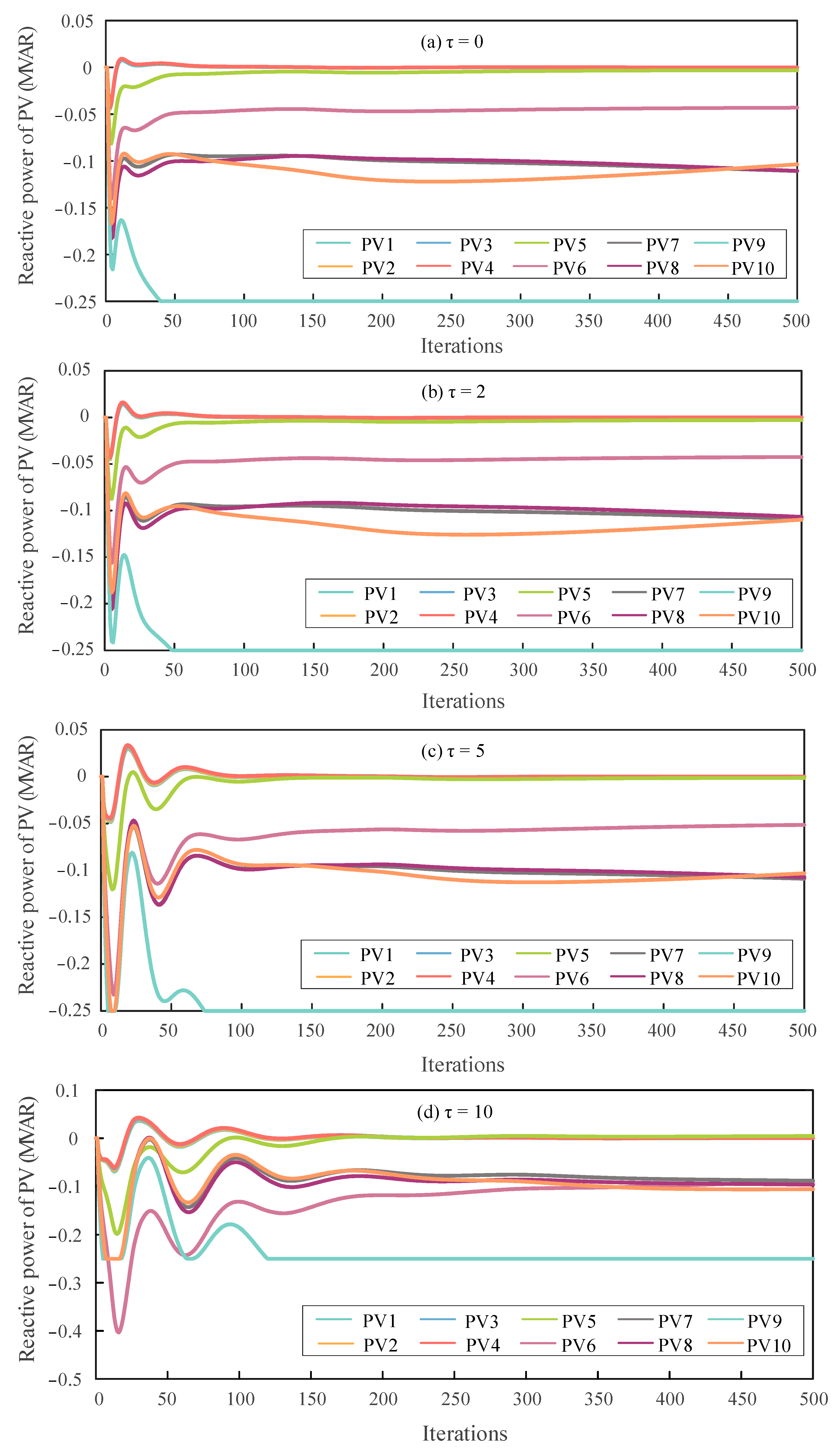
The paper investigates the impact of feedback delay length on the performance of the proposed voltage control method. Figure 3 and Figure 4, respectively, illustrate the node voltage profiles and reactive power outputs of the DN under feedback delays of 0, 2, 5, and 10 time steps. It is worth noting that the acceptable voltage range in this study is set to [0.95, 1.05] p.u., which is suitable for distributed implementation as it does not rely on global average voltage information.
As shown in Figure 3, increasing the number of feedback delay steps leads to larger initial fluctuations in node voltages and a slower convergence rate. This performance degradation arises because longer delays cause nodes to update their states based on outdated information, increasing the estimation error and weakening the responsiveness of the controller to voltage deviations. Nevertheless, as the algorithm gradually converges, the proposed method effectively regulates voltages within the acceptable range [0.95, 1.05] p.u., achieving noticeable reductions in steady-state voltage deviation.
Similarly, Figure 4 illustrates the variation trends of reactive power outputs at different nodes under various feedback delay settings. As the delay step increases, the magnitude of initial fluctuations becomes larger, and more iterations are required for the system to reach the final reactive power outputs. However, as the algorithm gradually converges, the reactive power outputs of all nodes eventually stabilize within their feasible ranges, effectively reducing the voltage deviations across the network.
Therefore, it can be concluded that under fixed feedback delays, the DOPP algorithm is still capable of effectively achieving voltage regulation and optimization. The reactive power outputs at all nodes can stably converge to feasible solutions, demonstrating good convergence and feasibility of the proposed method.

5.2. Dynamic Scenario Analysis

To evaluate the effectiveness of the proposed DOPP voltage control method under feedback delays in a dynamic environment, a time-varying distribution system is considered. The simulation is conducted on the IEEE 123-bus test system with high PV penetration. The daily load profile and PV generation curve are shown in Figure 5 and Figure 6, respectively. Notably, to test the regulation performance and robustness of the proposed algorithm under dynamic load disturbances, a non-standard load curve, as shown in Figure 5, was designed to simulate load fluctuation and disturbance conditions.
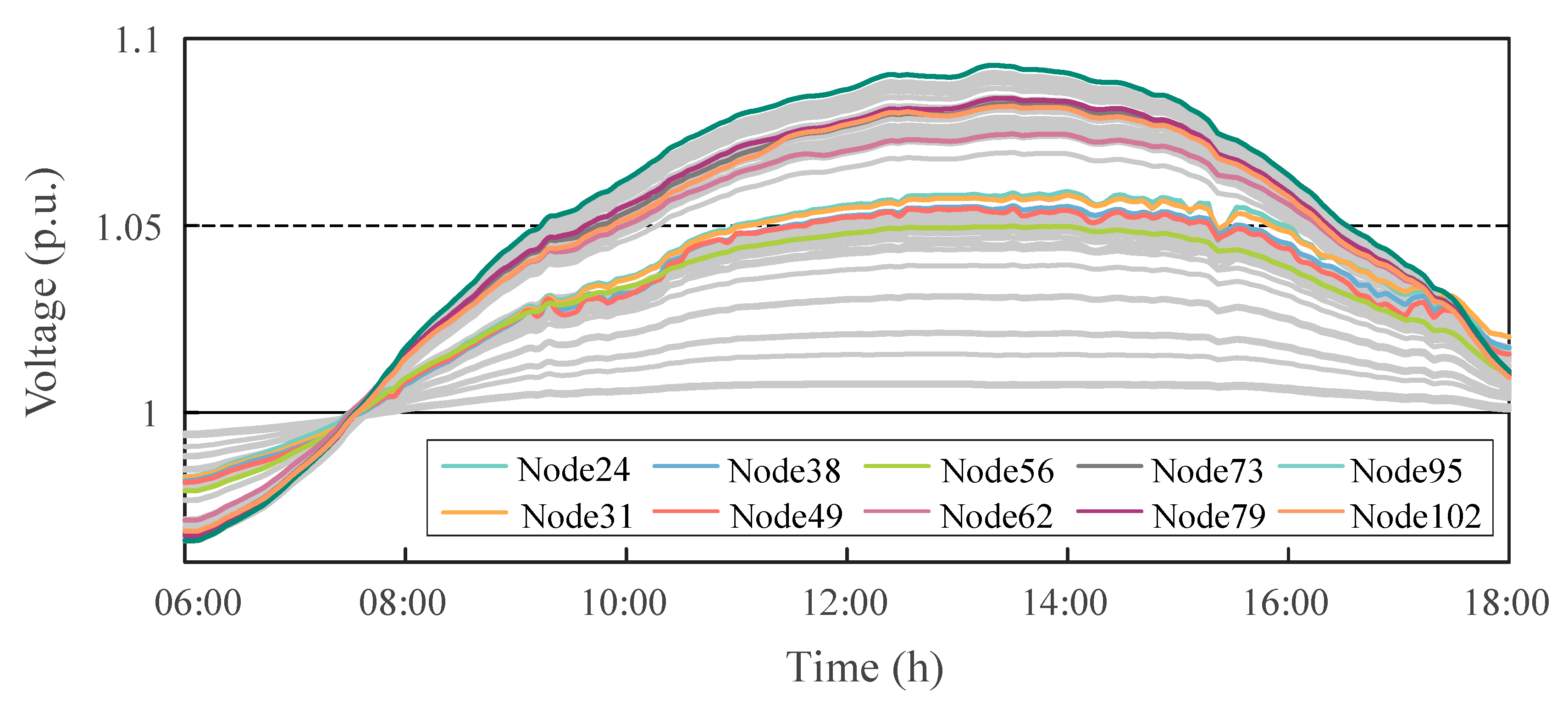
Figure 7 illustrates the voltage variations at typical PV nodes from 6:00 to 18:00 without any voltage control strategy applied. When the load is low but PV generation is high, some node voltages exceed 1.09 p.u. due to the lack of effective reactive power regulation, which is far above the allowable upper voltage limit of 1.05 p.u. In contrast, during early morning and evening hours, when the distribution system is heavily loaded and PV generation is unavailable, some nodes’ minimum voltages drop to around 0.96 p.u., near the acceptable lower bound of 0.95 p.u. This indicates that without any voltage control measures, the system suffers from significant voltage fluctuations and potential overvoltage or undervoltage risks. Therefore, it is necessary to coordinate the reactive power output of distributed PV inverters to dynamically compensate for local voltage, thereby alleviating voltage violations and enhancing the system’s voltage stability and operational reliability.
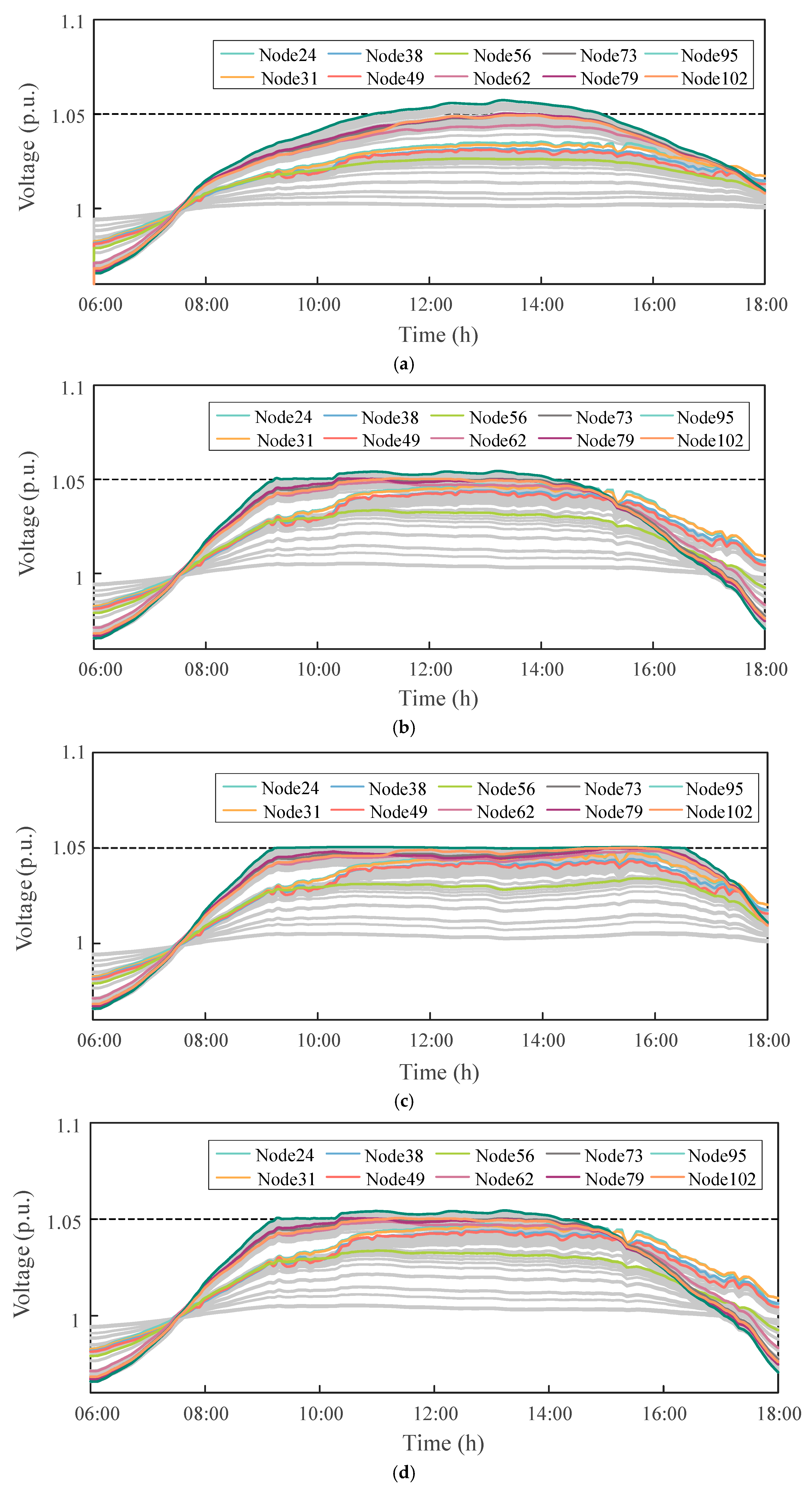
To further validate the regulation performance and robustness of the proposed distributed optimization control method under dynamic operating conditions, simulations were conducted based on the previously defined daily load and PV generation profiles. The authors selected droop control and incremental control for comparison and conducted a comparative analysis of the voltage regulation performance of different control strategies under dynamic conditions. Moreover, the performance of the DOPP algorithm was compared under both delay-free and fixed feedback delay scenarios (with a delay τ   =   2 ), in order to assess its robustness and adaptability in the presence of communication disturbances. The dynamic voltage profiles of key nodes under four control strategies are shown in Figure 8, including droop control, incremental control, DOPP algorithm without delay, and DOPP algorithm with fixed feedback delay.
From Figure 8, it can be observed that all four control scenarios are able to mitigate the voltage violation issues caused by PV output fluctuations to a certain extent, thereby achieving dynamic voltage regulation. Droop control performs local regulation based on a predefined linear voltage–reactive power (V–Q) characteristic. Although this method is simple and easy to implement, its flexibility is limited, resulting in noticeable voltage violations at certain nodes. Incremental control iteratively adjusts reactive power injections to progressively suppress voltage deviations. This improves control accuracy compared to droop control, yet the response speed remains insufficient when facing rapid changes in load or PV generation.
Compared with other strategies, the proposed DOPP control approach, which relies on a distributed optimization mechanism based on neighboring information, achieves faster and more accurate responses to system disturbances, exhibiting superior dynamic regulation capability and steady-state performance. Under zero feedback delay, the DOPP algorithm provides the best voltage control performance, with node voltages quickly converging and stably maintained within the acceptable range of [0.95, 1.05] p.u. When fixed feedback delay τ   =   2 is introduced, the initial response speed of the algorithm slightly decreases, and the voltage fluctuations slightly increase. However, the system still achieves stable convergence within a limited number of iterations, and the final control outcome remains close to the no-delay scenario, demonstrating strong robustness.
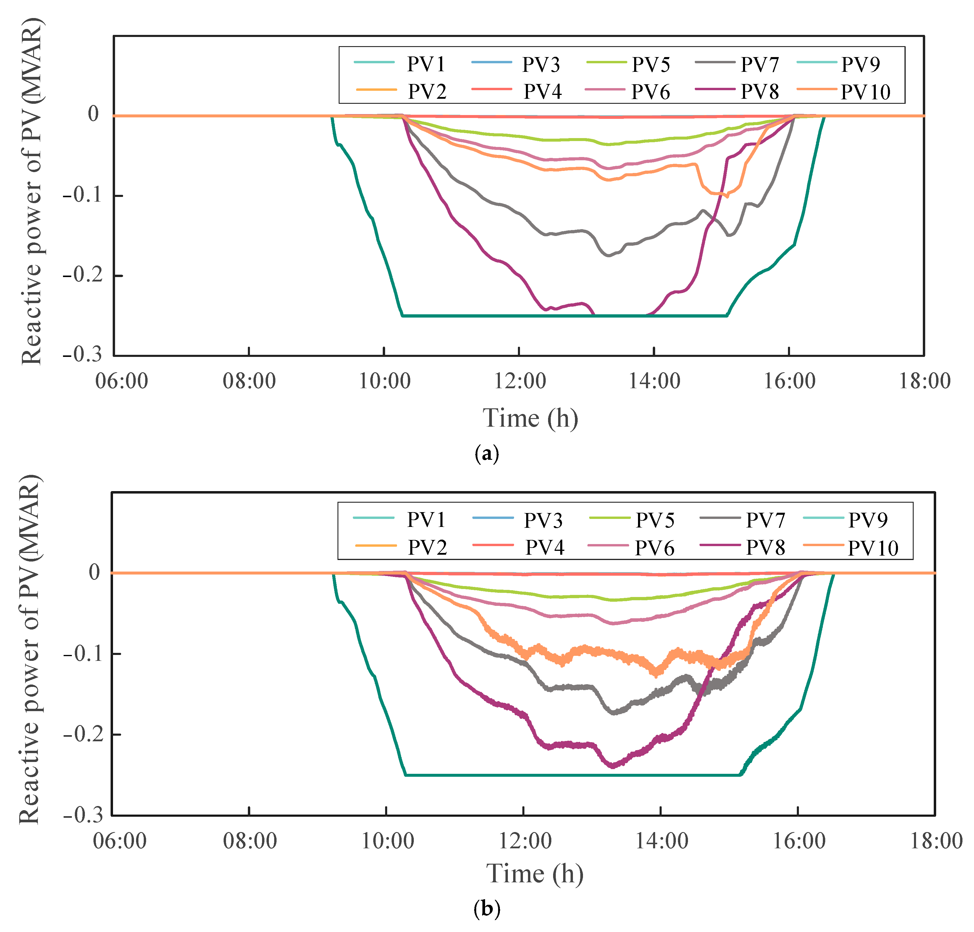
Figure 9 shows the time evolution of reactive power outputs at PV nodes under the DOPP algorithm, with and without feedback delay. It can be observed that there are noticeable differences in the reactive power trajectories among PV nodes. The primary reason for these differences lies in the DOPP algorithm’s reliance on local voltage measurements and neighbor-based communication, rather than global system information. The varying electrical locations and local voltage fluctuations within the IEEE 123-bus system also result in varying reactive power responses across PV units. Meanwhile, a clear discrepancy is observed between the two cases, indicating that feedback delay impacts the reactive power regulation process.
Under the DOPP control without feedback delay, each PV node is able to quickly respond to local voltage deviations through distributed computation and coordination with neighboring PV nodes, enabling fast adjustment and dynamic optimization of reactive power. The reactive power output curves exhibit smooth transitions with good synchronization and convergence, indicating effective coordination capability of the system. In contrast, when fixed feedback delays are introduced, PV nodes can only obtain outdated neighboring state information during updates, resulting in short-term prediction errors and delayed responses in local control.
As shown in Figure 9, some nodes experience short-term oscillations and overshoot during the regulation process due to state estimation errors caused by asynchronous information under feedback delays. Nevertheless, as time progresses, the DOPP algorithm with fixed feedback delays still achieves coordinated convergence of the reactive power outputs across all nodes, eventually stabilizing within their feasible control regions. These results demonstrate that the proposed method possesses strong adaptability and robustness, and is capable of effectively supporting the coordinated reactive power control of PV nodes in DNs.
Therefore, it can be concluded that although feedback delays may cause short-term lags and fluctuations in reactive power response, the DOPP algorithm still exhibits good long-term stability and convergence performance. It enables a more rational distribution of reactive power and enhances the dynamic coordination capability among nodes.

6. Conclusions

This paper proposes a distributed online reactive power optimization and control method for voltage regulation in DNs, and introduces a fixed-step feedback delay model to construct a more realistic asynchronous communication control scheme.
In terms of model formulation, based on a linearized power flow model, this paper formulates a quadratic objective to minimize voltage deviations by adjusting PV reactive power, subject to voltage and reactive power constraints.
Regarding communication topology modeling, and algorithm design, to address communication asymmetry in DNs, a column-stochastic matrix is used to form an asymmetric topology, and the push–sum method is applied for state normalization. Furthermore, a fixed-step feedback delay mechanism is introduced into the communication layer, enabling the design of a distributed online optimization algorithm that accommodates delayed information exchange.
Numerical simulations conducted on the modified IEEE 123-bus test system validate the effectiveness of the proposed method. Results show that (1) under static conditions, the DOPP algorithm with feedback delays exhibits stable convergence and effectively mitigates voltage violations within 50–100 iterations, regulating all nodal voltages into the permissible range of [0.95, 1.05] p.u.; (2) under dynamic conditions, the proposed method ensures effective voltage regulation and coordinated reactive power control, achieving 100% voltage compliance across all nodes throughout the simulation horizon. Compared with traditional droop and incremental control strategies, the proposed algorithm maintains all nodal voltages strictly within the permissible range of [0.95, 1.05] p.u., thereby improving voltage stability and demonstrating strong responsiveness and robustness under time-varying operating scenarios.
Considering the potential risk of communication interruptions in practical DN operations, future research will focus on analyzing and enhancing the adaptability and robustness of the proposed algorithm under partial communication failure scenarios, thereby improving its feasibility for real-world engineering applications.
Author Contributions

Software, X.Z.; data curation, X.Z., Z.N., and D.F.; writing—original draft, J.L.; writing—review and editing, Y.P. All authors have read and agreed to the published version of the manuscript.

Funding

This research was funded by the National Natural Science Foundation of China (NSFC) under Grant 52207093 and in part by Hunan Provincial Natural Science Foundation under Grant 2023JJ40150.

Institutional Review Board Statement

Not applicable.

Informed Consent Statement

Not applicable.

Data Availability Statement

Dataset available on request from the authors.

Conflicts of Interest

Yanjian Peng and Dingzhong Fan were employed by the company State Grid Hunan Electric Power Co., Ltd., Power Supply Service Center and Xiangtan Power Supply Company, State Grid Hunan Electric Power Company Limited. The remaining authors declare that the research was conducted in the absence of any commercial or financial relationships that could be construed as a potential conflict of interest.

References

  1. Xie, W.; Xiao, F.; Zheng, Y.; Kuang, G.; Tu, C.; Long, L.; Guo, Q. Analysis of the safe operation region of grid-connected converters under time-varying operating point conditions. Int. J. Electr. Power Energy Syst. 2025, 169, 110739. [Google Scholar] [CrossRef]
  2. Peng, X.; Xiao, F.; Tu, C.; Wang, L. A Fault-Tolerant Control for Hybrid Active Neutral-Point-Clamped Converters With Shared Redundant Unit Under Multiswitch Open-Circuit Fault. IEEE Trans. Ind. Electron. 2025, 72, 8550–8560. [Google Scholar] [CrossRef]
  3. Farivar, M.; Low, S.H. Branch Flow Model: Relaxations and Convexification—Part I. IEEE Trans. Power Syst. 2013, 28, 2554–2564. [Google Scholar] [CrossRef]
  4. McCornack, B.K.; Haider, R.; Majumder, S.; Pannala, S.; Schulz, N.N.; Annaswamy, A.; Srivastava, A.K. A Comparative Study of Centralized, Distributed and Local Volt-Var Control Algorithms on a Practical Distribution System. In Proceedings of the 2024 IEEE Power & Energy Society General Meeting (PESGM), Seattle, WA, USA, 19–22 February 2024; pp. 1–5. [Google Scholar]
  5. da Silva, E.L.; Lima, A.M.N.; Corrêa, M.B.R.; Vitorino, M.A.; Barbosa, L. A new centralized active and reactive power control strategy for voltage regulation in power distribution networks with high penetration of photovoltaic generation. In Proceedings of the 2016 17th International Conference on Harmonics and Quality of Power (ICHQP), Belo Horizonte, Brazil, 16–19 October 2016; pp. 823–828. [Google Scholar]
  6. Ibrahim, A.-W.; Xu, J.; Al-Shamma’a, A.A.; Farh, H.M.H.; Aboudrar, I.; Oubail, Y.; Alaql, F.; Alfraidi, W. Optimized Energy Management Strategy for an Autonomous DC Microgrid Integrating PV/Wind/Battery/Diesel-Based Hybrid PSO-GA-LADRC Through SAPF. Technologies 2024, 12, 226. [Google Scholar] [CrossRef]
  7. Nimpitiwan, N.; Chaiyabut, C. Centralized Control of System Voltage/Reactive Power Using Genetic Algorithm. In Proceedings of the 2007 International Conference on Intelligent Systems Applications to Power Systems, Kaohsiung, Taiwan, 5–8 November 2007; pp. 1–6. [Google Scholar]
  8. Hao, W.; Liu, B.; Yao, S.; Guo, W.; Huang, W. Reactive power optimisation of distribution network with distributed generation based on genetic and immune algorithm. J. Eng. 2019, 2019, 1280–1284. Available online: https://ietresearch.onlinelibrary.wiley.com/doi/10.1049/joe.2018.8859 (accessed on 8 June 2025). [CrossRef]
  9. Nguyen, H.M.; Torres, J.L.R.; Lekić, A.; Pham, H.V. MPC Based Centralized Voltage and Reactive Power Control for Active Distribution Networks. IEEE Trans. Energy Convers. 2021, 36, 1537–1547. [Google Scholar] [CrossRef]
  10. Lin, H.; Yu, T.; Zhang, G.; Zhang, X. Multi-Objective Reactive Power Optimization for Distribution Networks with High-Penetration of New Energy. In Proceedings of the 2023 International Conference on Smart Electrical Grid and Renewable Energy (SEGRE), Changsha, China, 16–19 June 2023; pp. 140–145. [Google Scholar]
  11. Patari, N.; Venkataramanan, V.; Srivastava, A.; Molzahn, D.K.; Li, N.; Annaswamy, A. Distributed Optimization in Distribution Systems: Use Cases, Limitations, and Research Needs. IEEE Trans. Power Syst. 2022, 37, 3469–3481. [Google Scholar] [CrossRef]
  12. Molzahn, D.K.; Dörfler, F.; Sandberg, H.; Low, S.H.; Chakrabarti, S.; Baldick, R.; Lavaei, J. A Survey of Distributed Optimization and Control Algorithms for Electric Power Systems. IEEE Trans. Smart Grid 2017, 8, 2941–2962. [Google Scholar] [CrossRef]
  13. Liu, H.J.; Shi, W.; Zhu, H. Hybrid Voltage Control in Distribution Networks Under Limited Communication Rates. IEEE Trans. Smart Grid 2019, 10, 2416–2427. [Google Scholar] [CrossRef]
  14. Tantrapon, K.; Jirapong, P.; Thararak, P. Mitigating microgrid voltage fluctuation using battery energy storage system with improved particle swarm optimization. Energy Rep. 2020, 6, 724–730. [Google Scholar] [CrossRef]
  15. Fotopoulou, M.; Tsekouras, G.J.; Vlachos, A.; Rakopoulos, D.; Chatzigeorgiou, I.M.; Kanellos, F.D.; Kontargyri, V. Day Ahead Operation Cost Optimization for Energy Communities. Energies 2025, 18, 1101. [Google Scholar] [CrossRef]
  16. Fusco, G.; Russo, M.; De Santis, M. Decentralized Voltage Control in Active Distribution Systems: Features and Open Issues. Energies 2021, 14, 2563. [Google Scholar] [CrossRef]
  17. IEEE Std 1547-2018 (Revision of IEEE Std 1547-2003)—Redline IEEE Standard for Interconnection and Interoperability of Distributed Energy Resources with Associated Electric Power Systems Interfaces-Redline; IEEE: Los Alamitos, CA, USA, 2018.
  18. Farivar, M.; Chen, L.; Low, S. Equilibrium and dynamics of local voltage control in distribution systems. In Proceedings of the 52nd IEEE Conference on Decision and Control, Firenze, Italy, 10–13 December 2013; pp. 4329–4334. [Google Scholar]
  19. Jahangiri, P.; Aliprantis, D.C. Distributed Volt/VAr Control by PV Inverters. IEEE Trans. Power Syst. 2013, 28, 3429–3439. [Google Scholar] [CrossRef]
  20. Li, N.; Qu, G.; Dahleh, M. Real-time decentralized voltage control in distribution networks. In Proceedings of the 2014 52nd Annual Allerton Conference on Communication, Control, and Computing (Allerton), Monticello, IL, USA, 30 September–3 October 2014; pp. 582–588. [Google Scholar]
  21. Cavraro, G.; Carli, R. Local and Distributed Voltage Control Algorithms in Distribution Networks. IEEE Trans. Power Syst. 2018, 33, 1420–1430. [Google Scholar] [CrossRef]
  22. Farivar, M.; Zho, X.; Chen, L. Local voltage control in distribution systems: An incremental control algorithm. In Proceedings of the 2015 IEEE International Conference on Smart Grid Communications (SmartGridComm), Miami, FL, USA, 2–5 November 2015; pp. 732–737. [Google Scholar]
  23. Lee, S.; Nedić, A.; Raginsky, M. Stochastic Dual Averaging for Decentralized Online Optimization on Time-Varying Communication Graphs. IEEE Trans. Autom. Control 2017, 62, 6407–6414. [Google Scholar] [CrossRef]
  24. Akbari, M.; Gharesifard, B.; Linder, T. Distributed Online Convex Optimization on Time-Varying Directed Graphs. IEEE Trans. Control Netw. Syst. 2017, 4, 417–428. [Google Scholar] [CrossRef]
  25. Lee, S.; Zavlanos, M.M. On the Sublinear Regret of Distributed Primal-Dual Algorithms for Online Constrained Optimization. arXiv 2017. [Google Scholar] [CrossRef]
  26. Abrahamsen, F.E.; Ai, Y.; Cheffena, M. Communication Technologies for Smart Grid: A Comprehensive Survey. Sensors 2021, 21, 8087. [Google Scholar] [CrossRef]
  27. Agarwal, A.; Duchi, J.C. Distributed delayed stochastic optimization. In Proceedings of the 2012 IEEE 51st IEEE Conference on Decision and Control (CDC), Maui, HI, USA, 10–13 December 2012; pp. 5451–5452. [Google Scholar]
  28. Li, J.; Chen, G.; Dong, Z.; Wu, Z. Distributed mirror descent method for multi-agent optimization with delay. Neurocomputing 2016, 177, 643–650. [Google Scholar] [CrossRef]
  29. Wang, H.; Liao, X.; Huang, T.; Li, C. Cooperative Distributed Optimization in Multiagent Networks With Delays. IEEE Trans. Syst. Man Cybern. Syst. 2015, 45, 363–369. [Google Scholar] [CrossRef]
  30. Bliman, P.-A.; Nedic, A.; Ozdaglar, A. Rate of Convergence for Consensus with Delays. In Proceedings of the 2008 47th IEEE Conference on Decision and Control, Cancun, Mexico, 9–11 December 2008; pp. 4849–4854. [Google Scholar]
  31. Cao, X.; Zhang, J.; Poor, H.V. Constrained Online Convex Optimization With Feedback Delays. IEEE Trans. Autom. Control 2021, 66, 5049–5064. [Google Scholar] [CrossRef]
  32. Bedi, A.S.; Koppel, A.; Rajawat, K. Beyond consensus and synchrony in decentralized online optimization using saddle point method. In Proceedings of the 2017 51st Asilomar Conference on Signals, Systems, and Computers, Pacific Grove, CA, USA, 29 October–1 November 2017; pp. 293–297. [Google Scholar]
  33. Bedi, A.S.; Koppel, A.; Rajawat, K. Asynchronous Online Learning in Multi-Agent Systems With Proximity Constraints. IEEE Trans. Signal Inf. Process. Netw. 2019, 5, 479–494. [Google Scholar] [CrossRef]
  34. Zhao, J.; Yao, M.; Yu, H.; Song, G.; Ji, H.; Li, P. Decentralized Voltage Control Strategy of Soft Open Points in Active Distribution Networks Based on Sensitivity Analysis. Electronics 2020, 9, 295. [Google Scholar] [CrossRef]
  35. Sandberg, I.W.; Willson, A.N. Some theorems on properties of DC equations of nonlinear networks. Bell Syst. Tech. J. 1969, 48, 1–34. [Google Scholar] [CrossRef]
  36. Mai, V.S.; Abed, E.H. Distributed optimization over weighted directed graphs using row stochastic matrix. In Proceedings of the 2016 American Control Conference (ACC), Boston, MA, USA, 6–8 July 2016; pp. 7165–7170. [Google Scholar]
  37. Li, H.; Wang, Z.; Xia, D.; Han, Q. Random Sleep Scheme-Based Distributed Optimization Algorithm Over Unbalanced Time-Varying Networks. IEEE Trans. Syst. Man Cybern. Syst. 2021, 51, 5244–5253. [Google Scholar] [CrossRef]
  38. Kempe, D.; Dobra, A.; Gehrke, J. Gossip-based computation of aggregate information. In Proceedings of the 44th Annual IEEE Symposium on Foundations of Computer Science, 2003. Proceedings., Cambridge, MA, USA, 11–14 October 2003; pp. 482–491. [Google Scholar]
  39. Nedić, A.; Olshevsky, A. Distributed Optimization Over Time-Varying Directed Graphs. IEEE Trans. Autom. Control 2015, 60, 601–615. [Google Scholar] [CrossRef]
  40. Xi, C.; Khan, U.A. DEXTRA: A Fast Algorithm for Optimization Over Directed Graphs. IEEE Trans. Autom. Control. 2017, 62, 4980–4993. Available online: https://ieeexplore.ieee.org/document/7862143 (accessed on 8 June 2025). [CrossRef]
  41. Xi, C.; Khan, U.A. Distributed Subgradient Projection Algorithm Over Directed Graphs. IEEE Trans. Autom. Control. 2017, 62, 3986–3992. [Google Scholar] [CrossRef]
  42. Xi, C.; Mai, V.S.; Xin, R.; Abed, E.H.; Khan, U.A. Linear Convergence in Optimization Over Directed Graphs With Row-Stochastic Matrices. IEEE Trans. Autom. Control. 2018, 63, 3558–3565. [Google Scholar] [CrossRef]
  43. Xie, P.; You, K.; Tempo, R.; Song, S.; Wu, C. Distributed Convex Optimization with Inequality Constraints over Time-Varying Unbalanced Digraphs. IEEE Trans. Autom. Control. 2018, 63, 4331–4337. [Google Scholar] [CrossRef]
Figure 1. Framework of the proposed distributed voltage control for DNs based on the DOPP algorithm with feedback delays.
Technologies 13 00327 g001
Figure 2. The modified IEEE 123-bus standard test system.
Technologies 13 00327 g002
Figure 3. Voltage profiles across all PV nodes under different feedback delay steps.
Technologies 13 00327 g003
Figure 4. Reactive power outputs of PV nodes under different feedback delay steps.
Technologies 13 00327 g004
Figure 5. Active power curve of the load.
Technologies 13 00327 g005
Figure 6. Active power curve of the PV.
Technologies 13 00327 g006
Figure 7. Voltage profiles of critical nodes without control.
Technologies 13 00327 g007
Figure 8. Dynamic voltage profiles of critical nodes in the IEEE 123-bus system under four different control strategies: (a) Droop control; (b) Incremental control; (c) DOPP control; (d) DOPP control with delay.
Technologies 13 00327 g008
Figure 9. Reactive power output curves of PV nodes under DOPP control: (a) DOPP control without delay; (b) DOPP control with fixed delay ( τ   =   2 ).
Technologies 13 00327 g009
Table 1. Comparison of related methods and the proposed approach.
AlgorithmUnderlying
Methodology
Voltage ConstraintReactive Power ConstraintFeedback DelayCommunicationUnbalanced
Communication
[1]Centralized OPFPenalization in costNot consideredNot consideredNot neededNot considered
[15,16,17]Droop controlSatisfiedNot consideredNot consideredNot neededNot considered
[19,20]Incremental controlSatisfiedConsideredNot consideredNot neededNot considered
[23]Primal–dualPenalization in costConsideredNot consideredLocal commNot considered
[25]Delayed optimizationPenalization in costNot consideredConsideredLocal commNot considered
[29]Online optimizationPenalization in costNot consideredConsideredLocal commNot considered
Our workDOPPSatisfiedConsideredConsideredLocal commConsidered
Disclaimer/Publisher’s Note: The statements, opinions and data contained in all publications are solely those of the individual author(s) and contributor(s) and not of MDPI and/or the editor(s). MDPI and/or the editor(s) disclaim responsibility for any injury to people or property resulting from any ideas, methods, instructions or products referred to in the content.