Abstract
There are numerous methods available for evaluating leg length discrepancy (LLD), ranging from classic clinical techniques to advanced systems based on sophisticated and expensive equipment, as well as rudimentary manual adjustment mechanisms for the prosthesis by specialists. However, unilateral amputee patients often face difficulties in accessing these solutions. They either lack the necessary equipment or do not have a medical specialist available to assist them in preventing postural imbalances. This study proposes the first smartphone-based computer vision system that evaluates and automatically compensates for leg length discrepancy in transtibial prostheses, offering a low-cost, accessible, and fully autonomous alternative to existing solutions. The method was tested using complex metrological systems. The application of the proposed method demonstrated its effectiveness in correcting simulated LLD for various values. Experimental validation demonstrated the system’s ability to restore symmetry in simulated LLD cases within the 1–10 mm range, achieving a relative compensation error of 2.44%. The proposed method for correcting LLD, based on computer vision and integrated into a smartphone, represents a significant advancement in restoring symmetry for unilaterally amputated patients. This technology could provide an accessible, efficient solution, thereby reducing the need for frequent prosthetist visits and enhancing user autonomy.
1. Introduction
Prosthetic devices are essential for individuals with limb amputations [1], helping restore mobility and independence. While upper limb amputees face challenges with grasping [2] and biosignal-based control [3], individuals with lower limb prostheses also face significant limitations—and one that is often overlooked is leg length discrepancy (LLD). This condition arises from inequality between the lower limbs, resulting in biomechanical imbalances. Extensive research has been dedicated to investigating this subject, resulting in the identification of adverse alterations in the subject’s body, including pathological changes in gait, spinal issues, and other complications [4,5].
The severity of these effects is determined by the magnitude of the discrepancy and the underlying etiology. The magnitude of LLD has been classified into three categories: mild LLD (0–30 mm), moderate LLD (30–60 mm), and severe LLD (greater than 60 mm) [6]. Recent research findings have indicated significant variations in the thresholds at which LLD becomes problematic for the human body. For instance, studies have demonstrated that an LLD of up to 5 mm can result in long-term physical complications [7], while an LLD ranging from 5 to 10 mm has been observed to affect the user [4,8]. It is posited by other research that an LLD of 20 mm may be tolerated [8,9], although such a condition may still result in frequent dysfunctions.
1.1. Current Methods for Assessing Limb Length Discrepancy
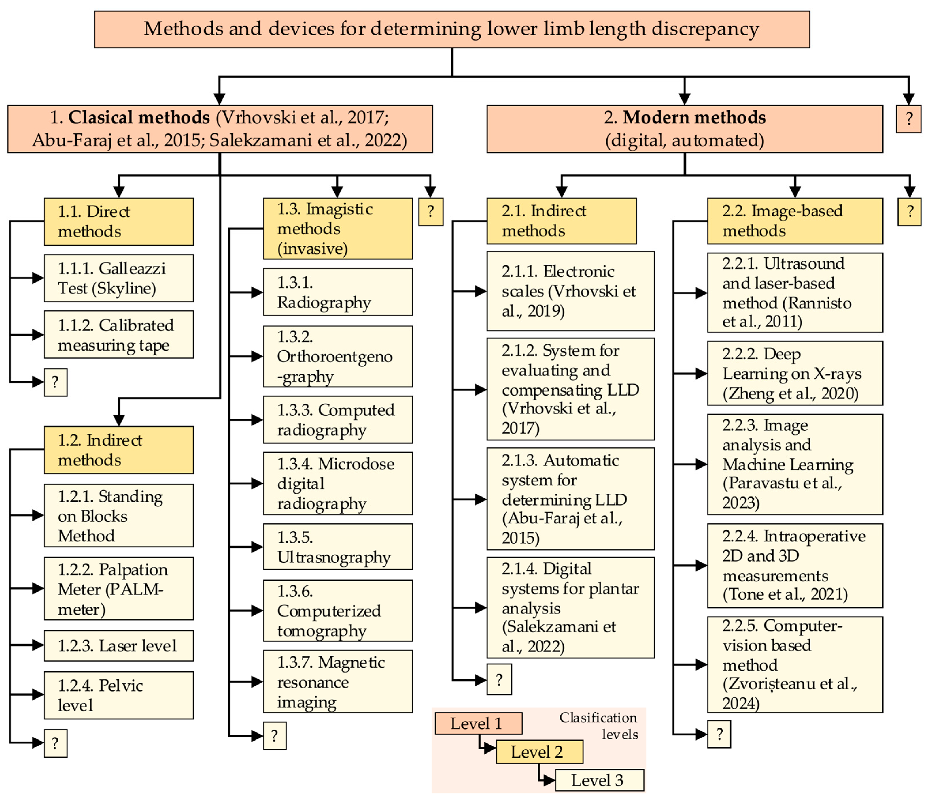
In order to receive appropriate compensation, it is essential to accurately quantify LLD. The quantification of LLD is carried out through functional measurements [8] and several static methods described in the specialized literature. These solutions have been visually classified and hierarchized in this paper in order to provide an overview of the methods and devices used for LLD quantification. A limited selection of these solutions has been previously documented in [10,11]. To critically track the current state of the techniques for LLD assessment, the idea diagram method [12] was used, which allowed for systematic classification and visualization of the methods and representative devices for determining leg length discrepancy found in the specialized literature on the subject.
As illustrated in Figure 1, the methods and devices are categorized into two primary subdomains.
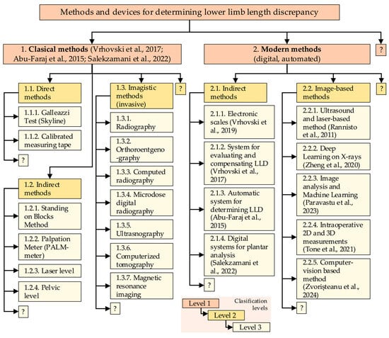
Figure 1.
Three-level classification of methods and devices used in LLD evaluation [11,13,14,15,16,17,18,19,20].
These subdomains are not confined to the following examples (as indicated by the use of “?”): (1) classical clinical methods (direct, indirect, and imaging-based), which are well-known and not emphasized in this paper, and (2) modern, automated solutions that are applied through indirect procedures with biomechatronic, electronic devices, or image-based solutions using specialized digital programs, sometimes combined with clinical imaging methods. The authors’ primary focus is on the second category, a subject of particular relevance in the context of this paper.
Contemporary indirect methods involve the implementation of electronic systems positioned beneath the subject’s feet during analysis. These devices include both classical instruments, such as electronic scales, which find primary application in experimental settings, and advanced mechatronic systems capable of detecting changes in the center of mass (CoM) triggered by a shorter limb [11]. These systems are designed to compensate for the difference in weight, thereby restoring the subject’s body to a state of symmetry. The value by which these systems re-balance the body is equivalent to the LLD value. A similar principle underlies plantar analysis, a functional assessment of LLD [13,14,15].
In the pursuit of non-invasive methods, alternative approaches have been developed, employing ultrasound or a combination of ultrasound and lasers. One such example is the utilization of an ultrasound probe affixed to a rod, accompanied by a laser system to measure the distance from the ground to the rod. This rod is then automatically maneuvered by a linear actuator, based on ultrasound images, to identify the highest point of the femoral head [16]. Other systems involve the loading of radiograms into machine learning or deep learning systems, which are then compared and classified to determine LLD [17,18]. Intraoperative methods are also employed in specific surgical procedures [19].
Another LLD assessment method is based on computer vision, utilizing the video camera of a smartphone to detect a series of strategically placed markers on the subject. This method enables the rapid, non-invasive, and cost-effective quantification of LLD [20].
Regular evaluation of LLD is imperative for prosthetic patients. These individuals require periodic visits to medical specialists to ensure congruence between the prosthetic limb and the biological limb, thereby averting the onset of LLD and the ensuing complications. This is particularly salient in the case of pediatric patients undergoing growth, as their biological processes are subject to variability [8,21,22]. Special attention must be given to post-amputation patients when they begin using a definitive prosthesis, which no longer resembles the biological limb that was amputated. In such cases, patients initially use a temporary prosthesis until the residual limb’s final shape is defined. These patients undergo regular adjustments to the length of the prosthesis, for reasons including preventing the occurrence of LLD [23].
1.2. Current Adjustable Lower Limb Prostheses
Prosthetic systems developed to ensure periodic length adjustments are described in [24] and further elaborated upon in this paper. To provide a clearer visual presentation, the prosthetic systems have been hierarchically organized in this study, using the idea diagram in Figure 2. This emphasizes the fact that they represent manual technical solutions. Following a clinical evaluation employing various methods, manual length adjustments to the prosthesis may be undertaken. It is important to note that these systems lack automation and, as such, are prone to errors.
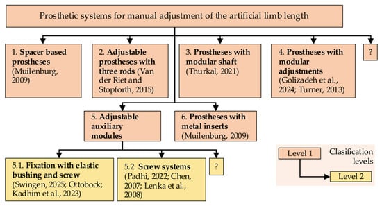
Figure 2.
Two-level classification of prosthetic systems for manual adjustment of the artificial limb [22,23,25,26,27,28,29,30,31,32,33].
Another prosthetic system, developed to automatically equalize leg length discrepancies in growing children, utilizes a Master–Slave mechanism. This system utilizes the inclination measurement of the lower limbs in unilateral prosthetic patients, with a specialized system regulating an extensible prosthetic module that compensates for the LLD [24]. While this system is operational and offers tangible benefits to the user, it does not satisfy the criterion of being an accessible, everyday home device, as it is specialized equipment requiring dedicated hardware.
1.3. Bridging the Gap: Accessible Automation for LLD Compensation
Currently, there is a notable absence of cost-effective, automated solutions capable of evaluating and compensating for leg length discrepancy (LLD) in real time. Specifically, there is no functional system that provides a closed-loop connection between LLD evaluation and compensation using an accessible, non-dedicated device, such as a smartphone. This is especially relevant for patients with unilateral amputations who require frequent adjustments due to growth and for patients undergoing rehabilitation after amputation, as changes to the residual limb necessitate regular prosthetic adjustment. In children, the prosthesis can function as a long-term adaptive tool throughout the growth and development period, thereby helping to maintain body symmetry. Developing such a system would allow for real-time image capture and automatic prosthesis alignment relative to the intact limb. This would eliminate the need for clinical supervision and offer a patient-centered solution.
The proposed system is characterized by its originality, functionality, and autonomy. It integrates real-time evaluation of LLD with mechanical compensation, a feat made possible by the utilization of a smartphone. The proposed methodology entails the detection of LLD through image processing, underpinned by a novel implementation of a newly designed algorithm, and involves the incremental adjustment of prosthesis length via closed-loop control. This innovative solution has the potential to effectively replace a set of prostheses of different lengths. It is particularly advantageous for transtibial amputees in developing regions, as it does not require clinical supervision and utilizes low-cost, accessible hardware.
The initial step in addressing LLD in amputee patients is a clinical evaluation of LLD using a standardized method. The evaluation is conducted by a medical specialist equipped with a proper device to determine the LLD. Following this evaluation, the prosthetist undertakes a manual adjustment of the prosthesis length, or, in instances where modification is unfeasible, replaces it with an appropriately sized prosthesis.
The present study has developed a prosthesis that utilizes computer vision to address LLD, with a focus on the transtibial aspect. This prosthesis is designed to be adaptable, and its design is based on smartphone technology, which is a technology that the user typically already possesses. The prosthesis’s development encompassed multiple stages, including the creation of a computer vision-based application for LLD compensation and the establishment of an experimental setup for laboratory testing of the prototype. The results obtained demonstrate the functionality of the first automated LLD compensation method, based on computer vision, managed through a smartphone and integrated into a transtibial prosthesis. The present study makes a novel contribution by introducing the first integrated method that combines computer vision-based assessment and real-time compensation of leg length discrepancy directly within a transtibial prosthesis. In contrast to prevailing methodologies that depend on specialized equipment or manual interventions, the proposed solution uses a standard smartphone and an adaptive prosthetic module to automatically restore limb symmetry. Extensive experimental validation was conducted, and the system demonstrated high accuracy and repeatability. It is a low-cost, accessible alternative to existing methods and demonstrates strong potential for home use, particularly among children or patients in remote areas.
2. Materials and Methods
The primary objective of this study was to develop and evaluate an application integrated into a smartphone. This application was designed to assist unilateral amputee patients with a transtibial prosthesis during the post-amputation recovery period or during the growth phase.
The prosthesis was designed to automatically adjust its length, thereby preventing the occurrence of limb length discrepancies during the post-amputation recovery period. At this stage, the residual limb undergoes dimensional changes and does not yet have a stabilized shape. At present, prosthetic patients require periodic adjustments of the prosthesis length to maintain an optimal fit and ensure body symmetry, thus preventing the onset of secondary degenerative conditions.
2.1. General Architecture of the Self-Adaptive Temporary Transtibial Prosthesis
The prosthetic system was designed to utilize a smartphone as a key component to assist the entire process, from evaluating the limb length discrepancy (LLD) to compensating for this issue faced by prosthetic users.
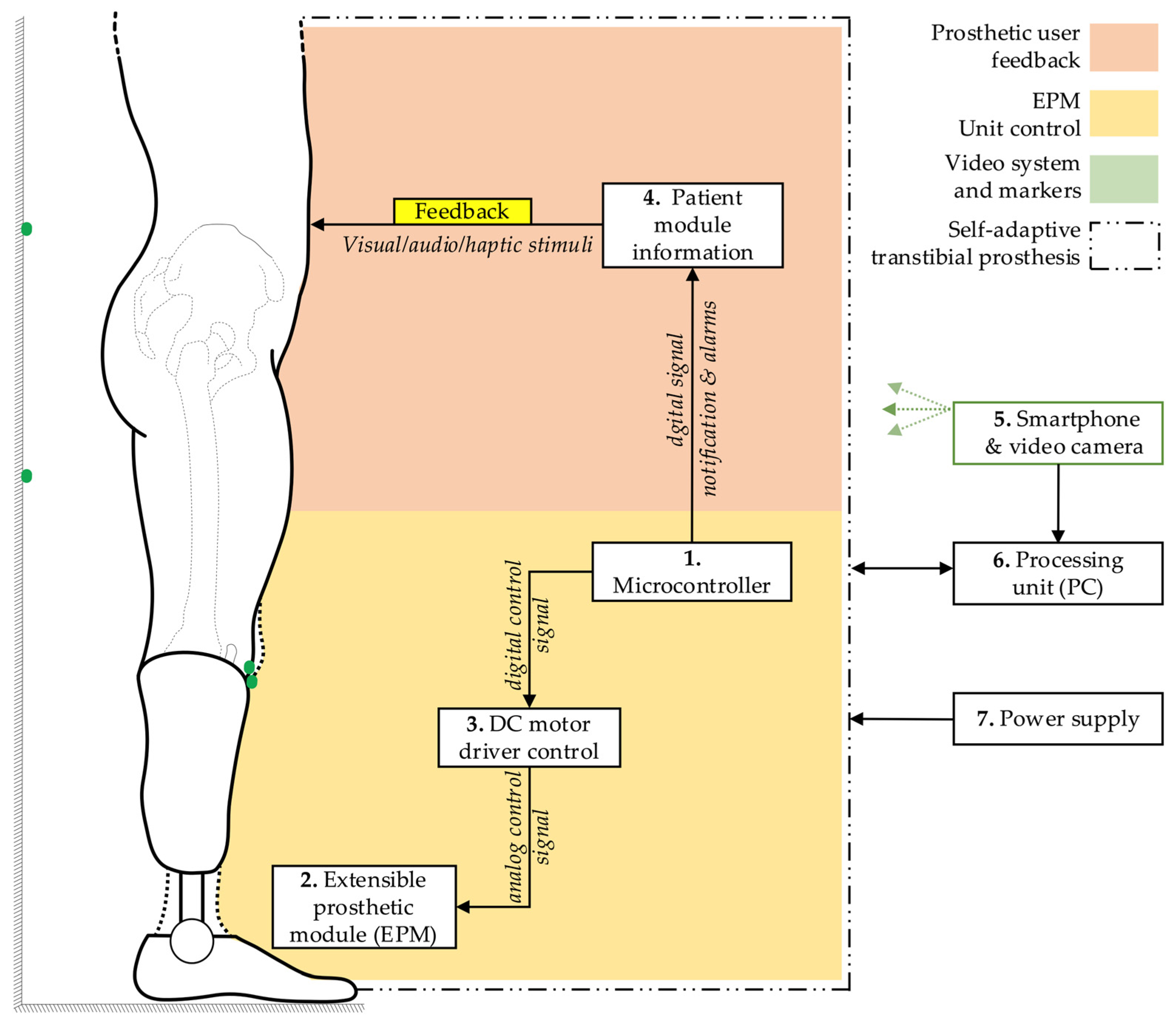
The fundamental block diagram of the system for detecting and correcting the simulated limb length discrepancy is presented in Figure 3. The architecture encompasses a microcontroller (1), which orchestrates the functional connections and control processes of the extensible prosthetic module (3) (EPM). The microcontroller is responsible for orchestrating the interaction with the integrated actuator in the EPM via a control driver. This ensures the operation of the EPM’s DC motor.
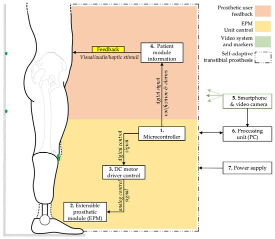
Figure 3.
General block diagram of the prosthetic system.
The block diagram also incorporates a user-prototype feedback loop facilitated by the functional link between the microcontroller and a notification module (4). This module provides real-time information to the user regarding the operations of the prosthetic system, thus enabling monitoring and adjustment of ongoing processes.
The detection of LLD is facilitated by a smartphone equipped with a video camera (5). The smartphone can be placed on a tripod or held manually by the user. It captures the necessary data, including a series of reference markers strategically placed on the prosthetic user and on the wall behind the user, and transmits this data wirelessly to a signal processing unit (6), which can be an interface connected to a PC. Subsequent to this, an image processing algorithm is applied, relevant data is extracted, and based on this, commands are sent to the electric actuator within the EPM.
As a result of these functional connections, the EPM is capable of adjusting the prosthesis length, thereby compensating for the existing lower limb length discrepancy. The entire prosthetic system is powered by an external power source (7) to avoid increasing the weight of the portable system. The displacement performed by the EPM is subsequently measured using instruments to evaluate the accuracy of the adjustments.
2.2. Flowchart of the Control Mechanism for Leg Length Discrepancy Compensation
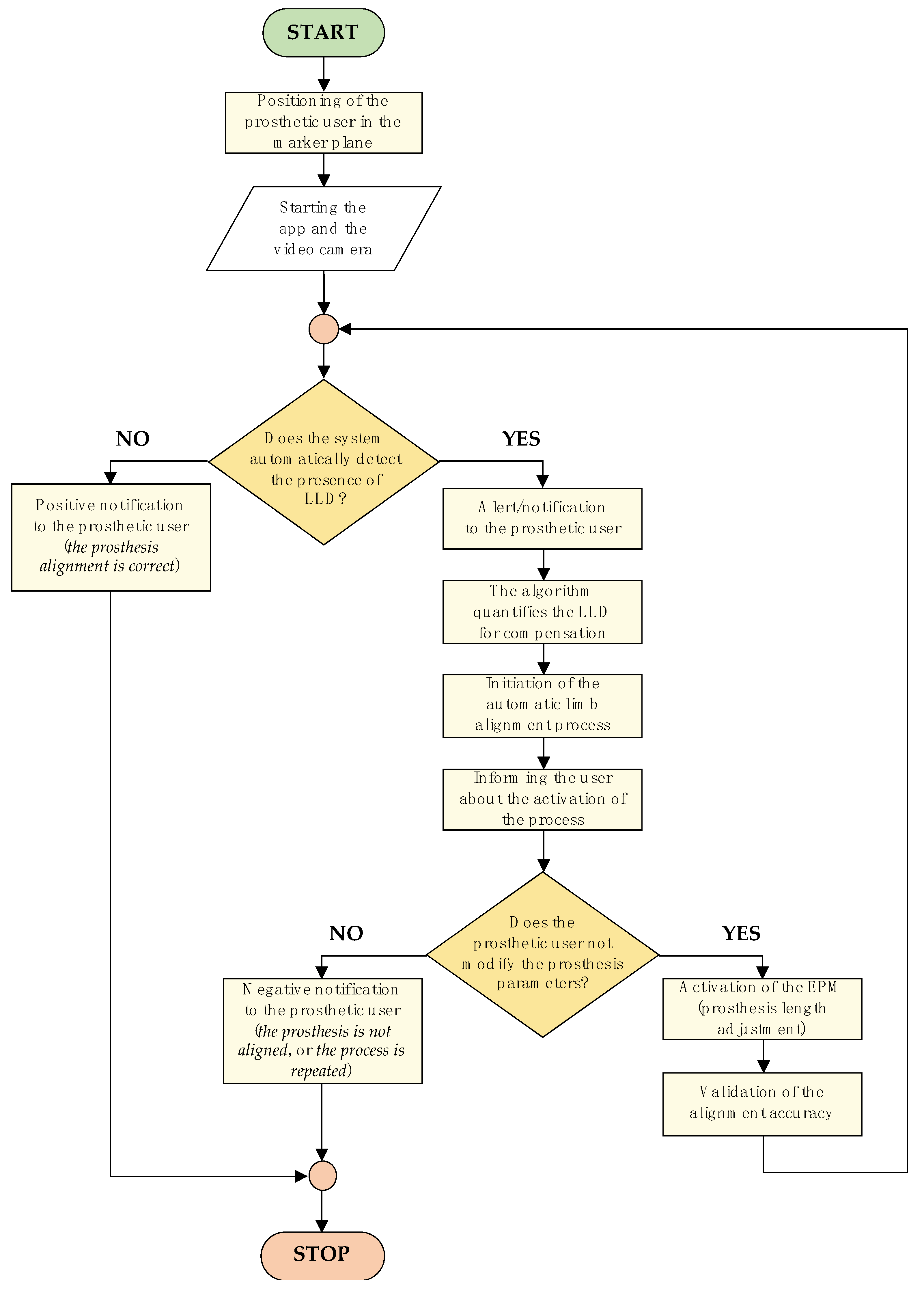
The control logic diagram of the LLD compensation mechanism, detailing the entire algorithm—from patient positioning in front of the marker-equipped plane to completion of the artificial limb alignment process—is illustrated in Figure 4.
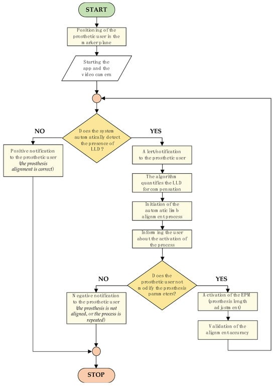
Figure 4.
Flowchart of the control mechanism for LLD compensation.
The algorithm commences with the positioning of the prosthetic user, who must assume a predefined stance. The process entails the utilization of markers positioned on the residual limb, the intact limb, and the background surface behind the subject. These markers are subsequently detected by the smartphone camera, facilitating the assessment of LLD.
The subsequent stage involves the LLD detection process, which is performed by processing the collected data using specially developed algorithms. Once LLD has been identified, the algorithm activates an automated prosthetic length adjustment system to compensate for the discrepancy and restore proper alignment of the artificial limb relative to the contralateral limb.
The LLD compensation is performed in real time based on feedback from the detection system, while the user receives continuous updates on the process status through a simple and accessible interface. Throughout this process, the user maintains active control over the device, with the ability to manually intervene for additional adjustments or to halt the compensation process if necessary.
This methodological approach facilitates extensive prosthetic customization, ensuring not only the correction of limb length asymmetries but also the prevention of secondary complications such as joint pain or muscular imbalances, which may arise from misaligned prosthetic devices.
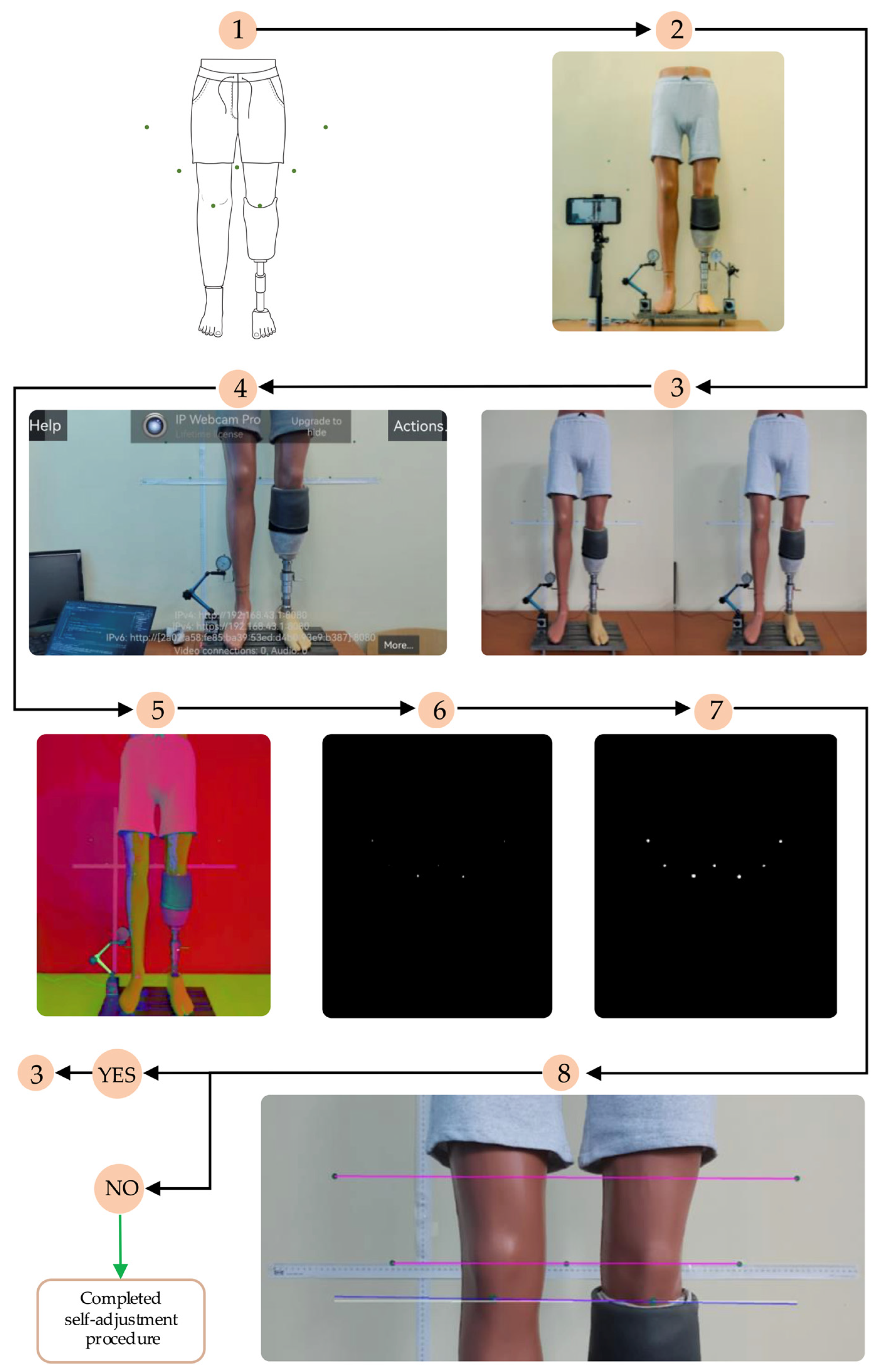
The subsequent paragraph delineates the image processing steps employed to detect markers and evaluate alignment prior to each compensation step. The smartphone is positioned in front of the mannequin at a distance of approximately 1.5 m and captures real-time images using the IP Webcam Pro© application. A leg length discrepancy is then simulated. The system is capable of detecting circular green markers, which are isolated from the background through the application of a segmentation threshold in the HSV (Hue, Saturation, Value) color space. A binary mask is generated to highlight only the green markers. Following the detection stage, morphological dilation operations are applied to enhance the contours. These are followed by the reconstruction of any interrupted regions within the marked area.
The centers of the detected markers are then connected with virtual lines. A comparison of the initial and final positions of these lines, prior to and following EPM activation, respectively, enables the system to assess the symmetry of the prosthetic user’s posture. In the event that the lines are found to be parallel and do not intersect, the adjustment process is halted, as symmetry is deemed to have been achieved. In the event that the lines intersect or are non-parallel, the algorithm identifies the discrepancy as persisting and repeats the compensation step. Each adjustment is followed by a brief delay, allowing for the capture of a new frame and re-evaluation.
2.3. Summary of the Computer Vision Algorithm for LLD Assessment
The image processing algorithm for detecting the visual markers and computing leg alignment is based on the approach presented in our previous work [20], where a non-invasive, HSV color space-based segmentation technique was employed to detect green-colored markers on the subject and background wall. First, RGB images are converted to HSV space, and a binary mask is created using empirically defined threshold ranges for hue, saturation, and value. Morphological operations, specifically dilation, are applied to close gaps between segmented regions.
Once the markers are isolated, their centroids are computed using first-order spatial image moments. Marker pairs are used to define lines for alignment: the prosthetic leg (knee line), the middle wall markers (middle line), and upper wall markers (upper line). The angle of each line relative to the image’s X-axis is computed using the atan2 function.
The alignment is assessed by comparing the knee line to the middle and upper wall lines. During calibration, baseline angles (θ_middle, θ_upper) are computed, and each new frame’s alignment is checked against these baselines using computed tolerances (tol_middle, tol_upper). Further details, including the full algorithm flow and marker configuration, are available in [20].
2.4. Calibration and Tolerance Derivation
A calibration procedure was performed using 60 frames captured in a known aligned pose. The angle between the prosthetic line and each wall reference line was computed, and the mean angle was stored as the nominal reference: θ_middle = 161.2°, θ_upper = 108.2°. For each set of frames, the standard deviation was computed, and tolerances were set as twice the standard deviation to cover 95% of natural variation. This yielded tol_middle = ±0.073°, tol_upper = ±0.90°. These tolerances were used as thresholds for detecting alignment in real-time operation.
3. Results
3.1. Technical Components of the Experimental Setup
The materials and devices utilized in the experimental research for developing the test stand dedicated to compensating for leg length discrepancy (LLD) using the computer vision-based application are presented in detail. The selection of these materials and equipment was based on performance criteria in relation to acquisition costs, compatibility with the technical requirements of the prototypes, and the accuracy necessary to obtain reliable results. The specifications of each component involved in constructing the test stand and prosthetic device prototypes are detailed, along with their role in achieving the established objectives.
The study further demonstrates the integration of these components into various functional devices or prototypes, enclosed in protective casings to ensure the safeguarding of electronic equipment and the overall efficiency of the system.
The implementation and testing of the LLD compensation method using computer vision involved the use of an extensible prosthetic module (EPM), as previously described in [24]. The EPM was adapted and integrated into a new experimental configuration, allowing it to be attached via standardized prosthetic pyramidal adapters. This adaptation was driven by the objective of optimizing a novel testing protocol, with the aim of ensuring conditions that closely resembled real-world usage. The final configuration of the setup is illustrated in Figure 5.
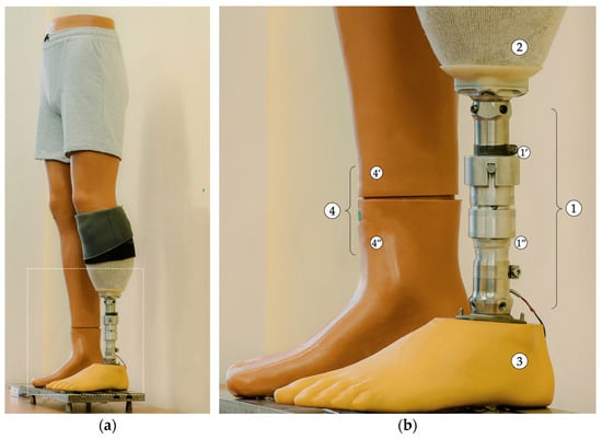
Figure 5.
Anterolateral view of the EPM attached to the mannequin’s residual limb. (a) Overall view. (b) Zoomed-in detail (1—EPM: 1’—mobile assembly; 1”—fixed assembly; 2—prosthetic socket; 3—prosthetic foot; 4—right lower limb growth simulation mechanism: 4’—fixed component; 4”—movable/adjustable component).
A mannequin with anatomical shaping was selected for the procedure, and a transtibial residual limb was created by sectioning the lower leg and modelling it to simulate the appearance and consistency of such a residual limb. The resulting residual limb was then covered with a 3 mm-thick silicone liner (Icecross Dermo® Cushion, Össur, Reykjavík, Iceland) and a custom-made prosthetic socket composed of a deformable material containing a standardized pyramidal adapter. In order to guarantee effective fixation and adequate suspension during testing, under conditions as close to real-life scenarios as possible, an ALPS Flex Sleeve prosthetic knee sleeve (ALPS® South, LLC, St. Petersburg, FL, USA) was also utilized. Finally, the EPM was attached to the prosthetic socket along with a SACH (solid-ankle cushion-heel) prosthetic foot using standardized prosthetic adapters.
The EPM was actuated by a CHR-GM25-370 12 V DC motor (TT Motor (HK) Industrial Co., Ltd., Hong Kong, China). A selection of the electrical parameters is highlighted in Table 1.

Table 1.
Selection of key technical parameters of the CHR-GM25-370-12 V DC motor [24,34].
The parameters listed in Table 1 are based on the manufacturer’s technical datasheet [34] and were used as selection criteria during the design of the EPM.
3.2. Architecture of the EPM Control Unit
To facilitate the functional connections of the direct-current motor that drives the EPM with the microcontroller contained in the development board, an L298N module with a double “H” bridge was utilized. As illustrated in Figure 6, the module integrates an L298 circuit and a 78M05 voltage regulator to 5 V.
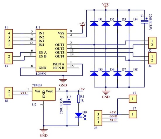
Figure 6.
Schematic diagram of the L298N module with a double H bridge [35].
A selection of technical features of interest for the driver controlling the DC motor is detailed in Table 2.
Table 2.
Main technical characteristics of the L298N motor driver [35,36].
To manage the control of the EPM, an ATmega328P microcontroller was utilized and integrated into the Arduino Nano development board, a cost-effective platform yet sufficiently performant to manage the control of the prosthetic module. The technical specifications pertinent to this board are enumerated in Table 3.
Table 3.
Technical parameters of the development board used [37].
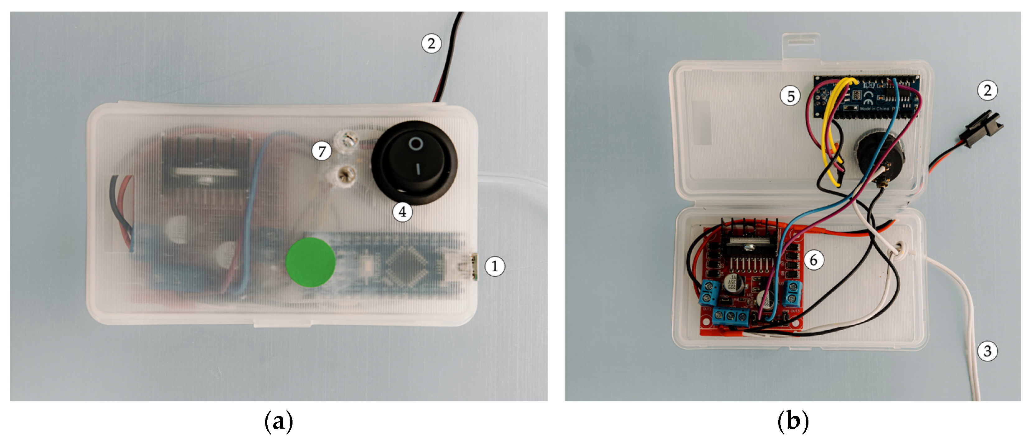
These electrical components were integrated into the prototype of the control unit (CU) of the EPM (see Figure 7). The prototype has the capacity to establish a connection with a PC interface via a USB connection. The following presentation will outline the primary electronic components of the system: the development board, which integrates the microcontroller; the motor driver, which is responsible for controlling the EPM; and the LED feedback module, which is used for visual feedback during operation.
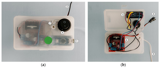
Figure 7.
Views of the EPM control unit (CU) (1—USB connection; 2—dedicated EPM connection; 3—12 V power supply circuit; 4—On/Off switch; 5—development board; 6—DC motor driver; 7—LED indicator module). (a) Exterior view. (b) Interior view.
Communication with the EPM is facilitated by a dedicated connection, ensuring synchronization and precise control of the prosthetic module. The device’s power supply is derived from a 12 V source, which is connected through a stabilized power circuit. The configuration of this circuit was meticulously designed to satisfy the energy requirements of the system, thereby facilitating uninterrupted operational continuity. The on/off power control is facilitated by a dedicated switch.
3.3. Final Test Configuration
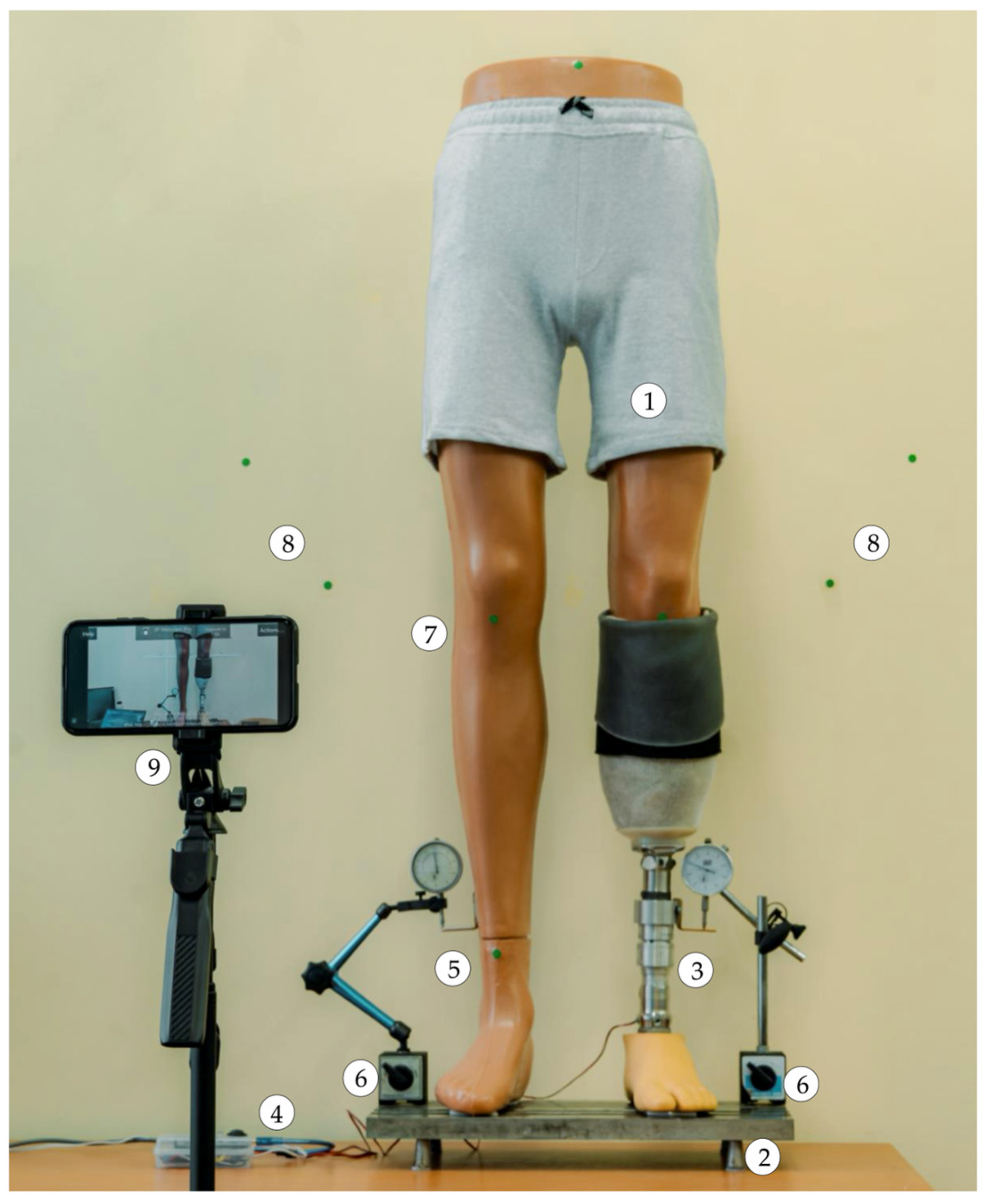
As illustrated in Figure 8, the final experimental setup was designed for simulating, detecting, and compensating for lower limb length discrepancies through image processing.
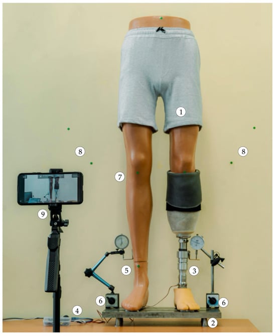
Figure 8.
Front view, overall, of the developed experimental setup (1—anatomical mannequin; 2—base plate; 3—EPM; 4—EPM control unit; 5—right lower limb growth simulation mechanism; 6—dial comparator; 7—markers on the mannequin; 8—pairs of markers on the surface behind the mannequin; 9—smartphone).
This configuration comprises an anatomical mannequin with a transtibial amputation affixed to a base plate, which is utilized for mechanical experimental testing. The left lower limb of the mannequin is attached to the EPM, which was meticulously aligned to ensure a precise fit with the mannequin’s anatomical structure.
The right lower limb is equipped with a mechanical system for simulating limb length growth. This system is based on a screw–nut mechanism that converts rotational motion into linear motion. The mechanism is manually operated by rotating a crank located at the posterior aspect of the right lower limb’s calf. To ensure continuous observation of the limb’s movements, two dial indicators were employed.
3.4. Experimental Testing of the Prosthetic System for LLD Correction
3.4.1. Incorporation of the LLD Detection Method into the Correction Algorithm
A methodology for evaluating limb length discrepancy (LLD) was previously validated in a separate publication [20]. In the present study, a novel component of the algorithm was evaluated, specifically for the automatic correction of LLD with the self-adjusting transtibial prosthesis. The adapted algorithm is illustrated in Figure 9.

Figure 9.
The algorithm for detecting and compensating for LLD (1—strategic placement of markers; 2—positioning the video camera in front of the mannequin; 3—simulating LLD: 3 mm and 5 mm; 4—using the IP Webcam Pro© application and managing the elongation or shortening of the EPM; 5—detecting the markers using the HUE method—Hue, Saturation, Value; 6—applying a binary mask for visualizing the markers; 7—morphological operations of dilation on the markers; 8—detecting LLD by comparing the initial position with the final position of the markers after activating the EPM (adapted from [20]).
In order to achieve a comprehensive understanding of the detection process, Figure 9 provides a concise overview of the requisite steps for determining LLD and the manner in which they are incorporated into the novel algorithm for correcting LLD using the transtibial prosthesis.
It is imperative to analyze the alignment errors between the detected markers on the two limbs to compensate for the leg length discrepancy. These discrepancies must be sufficiently minimal to guarantee the adequate adjustment of the prosthesis length. In this regard, the lines generated by the software must be nearly parallel, and the differences between them must be kept below a preset value, chosen according to the system tolerances. This alignment process is carried out by processing data regarding the positioning of the markers placed on both limbs and evaluating the errors against an acceptable tolerance, which guarantees the accuracy of the adjustment.
The prosthetic system under development operates through the implementation of a meticulously designed algorithm. Following the establishment of the reference positioning, the algorithm undertakes a comparison between the position of the blue line, which represents the alignment of the prosthesis, and the reference position. This is achieved by ensuring that both limbs (the intact and the artificial) are aligned. During this process, the algorithm calculates the angles formed between the two lines, and if the difference between them exceeds a predefined threshold, the EPM actuator is activated to align the artificial limb with the intact one [20].
Subsequent to this adjustment, the system performs a re-evaluation of the marker positions (returning to Step 3 in Figure 9) to ascertain if LLD persists. If the alignment errors, calculated based on the angle differences, are below a predefined limit, the EPM automatically stops the movement, concluding that the prosthesis position is correct and that the adjustment has been made according to the system’s requirements.
Consequently, the EPM functions in a continuous manner until the alignment discrepancies become sufficiently minimal, thereby enabling the prosthesis to attain an optimal position. Subsequent to the fulfilment of this condition (after Step 8 in Figure 9), the motor ceases operation automatically. This signifies that the process of leg length discrepancy compensation has been completed and that the prosthesis is correctly aligned.
3.4.2. Experimental Testing of the Prosthetic System
In the initial phase of the testing process, which entailed less complex measurements of EPM displacement, an alternative, more accessible equipment configuration based on direct contact was utilized.
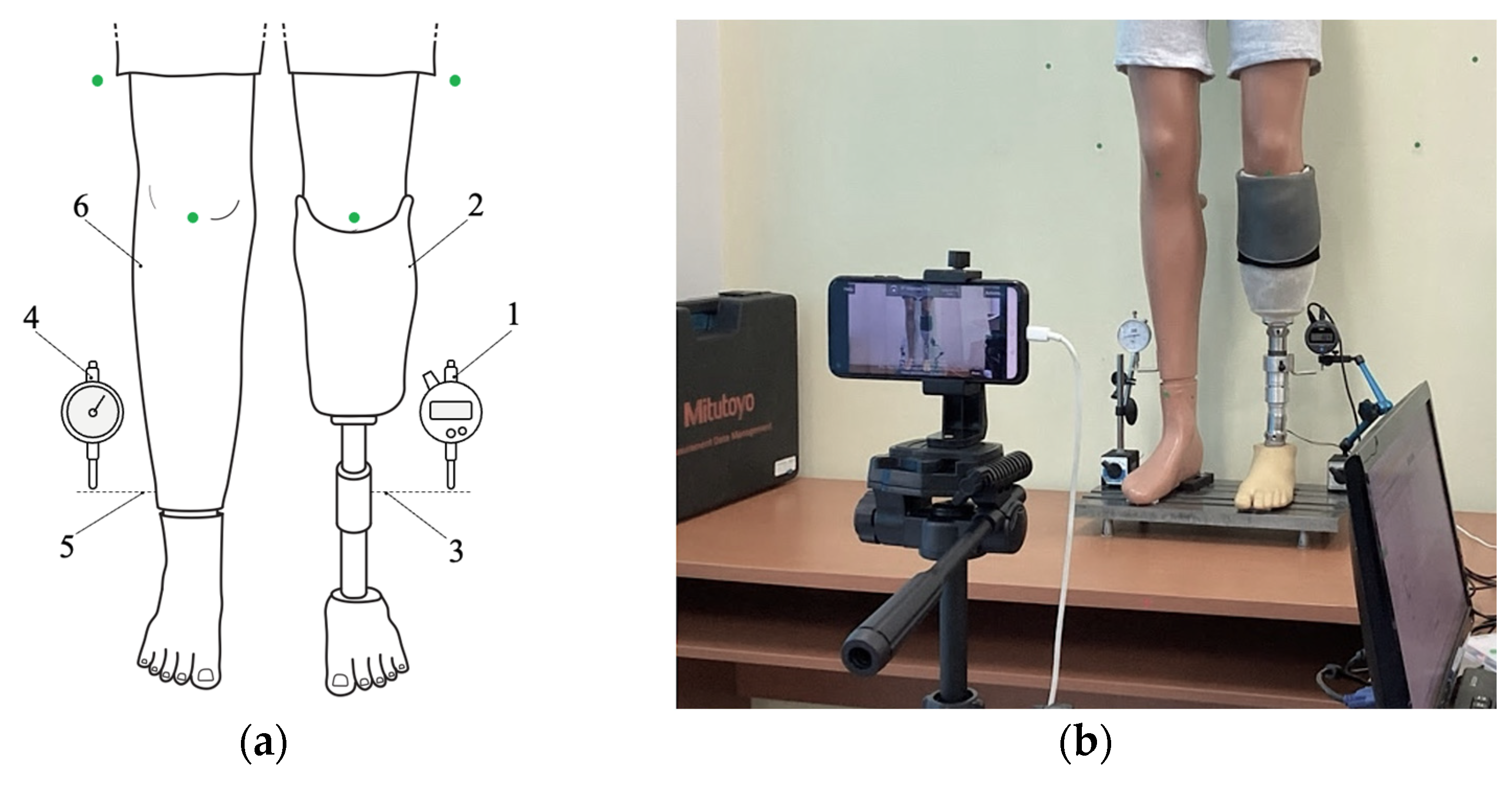
The capacity to compensate for LLD was the focus of this study, which employed a direct contact measurement technique to evaluate this capacity. The responses of the SATP and the automatic length adjustments of the extensible prosthetic module mounted on the test mannequin were monitored, as illustrated in Figure 10.
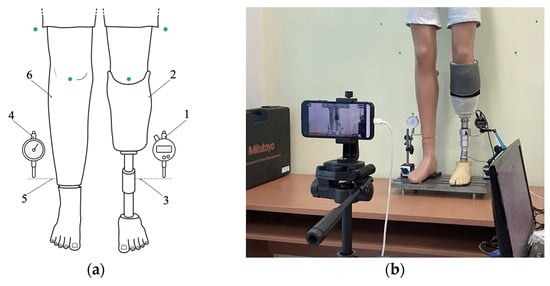
Figure 10.
Positioning of the devices used in the prosthesis behavior study: (a) schematic representation (1—digital dial gauge; 2—artificial limb; 3—temporary support blade; 4—classic dial gauge; 5—temporary support blade; 6—intact contralateral limb equipped with a mechanism for simulating LLD). (b) overview of the experimental setup, with the dial gauges in their operating positions.
The measurements were conducted using a digital comparator (1)—Mitutoyo Corporation, Kawasaki, Japan—that was placed in direct contact with the movable component of the EPM (2), which was attached to the residual limb (3). This attachment was facilitated by a temporary support blade (3) that was designed to extend the contact surface and facilitate direct interaction between the comparator’s probe and the displaceable element.
The experimental setup was designed to enable controlled simulation of body imbalance in the mannequin through a mechanism that mimics lower limb length discrepancy. The discrepancy, induced by the simulated difference in limb length, was addressed by employing a crank integrated within the mannequin and meticulously monitored with a dial comparator (4) attached to the movable portion of the intact contralateral limb (6) via a temporary support blade (5).
An Absolute Solar Digimatic Indicator, model ID-S1012SB (Mitutoyo Corporation, Kawasaki, Japan), was utilized and connected to a PC interface. The experimental data acquisition was performed using the dedicated software, MeasureLink USB-ITPAK, version 2.000 (Mitutoyo, MiCAT—Mitutoyo Intelligent Computer Aided Technology, Kanagawa, Japan) [38]. The software facilitated a reliable connection with the data acquisition device, the digital comparator, whose technical specifications are presented in Table 4.
Table 4.
Technical parameters of the Absolute Solar Digimatic Indicator [39].
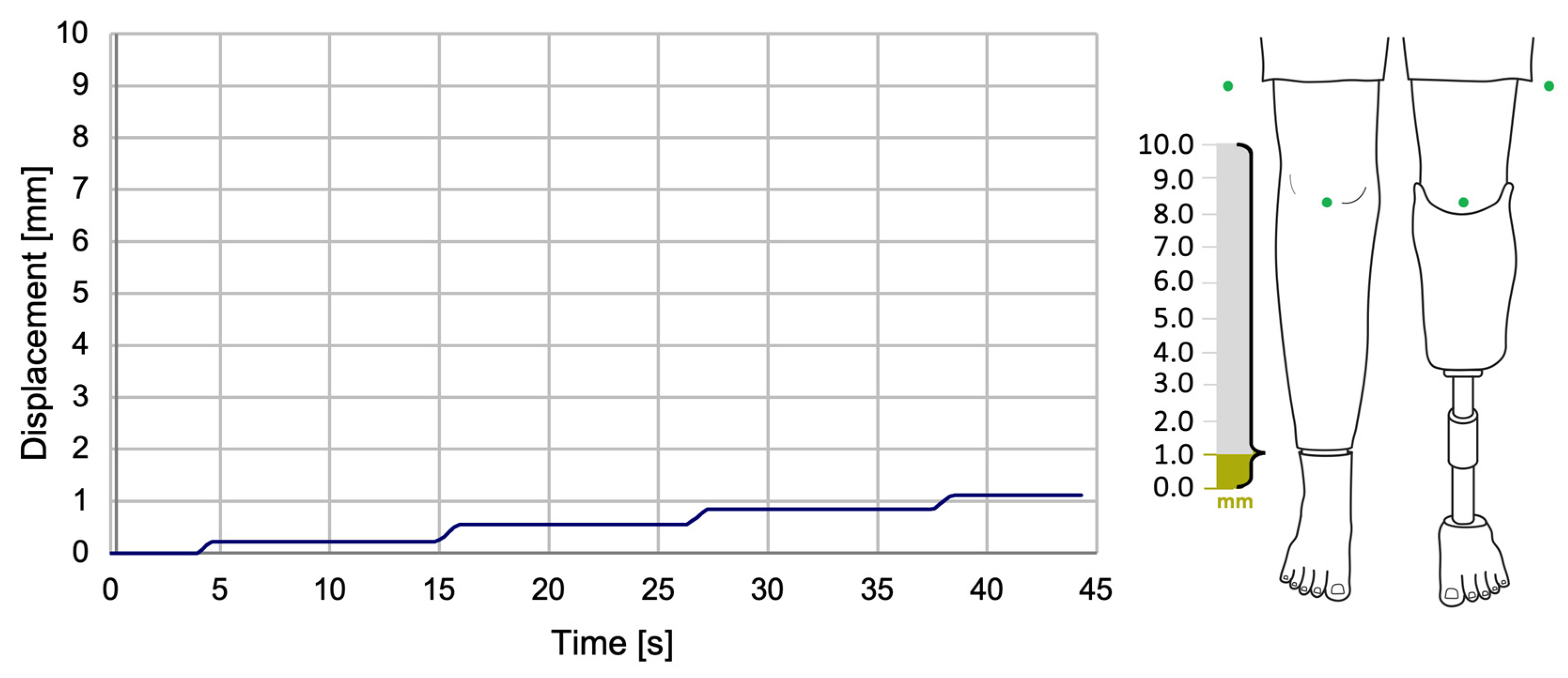
In the course of the experiments, a series of LLD values were systematically simulated. This was made possible by utilizing the LLD simulation mechanism integrated into the right limb of the test mannequin. The simulated LLD values ranged from 1 to 10 mm, with 1 mm increments. A selection of the experimental data obtained is presented in Figure 11.
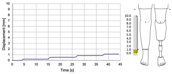
Figure 11.
The variation of SATP displacement during the compensation of a 1 mm LLD.
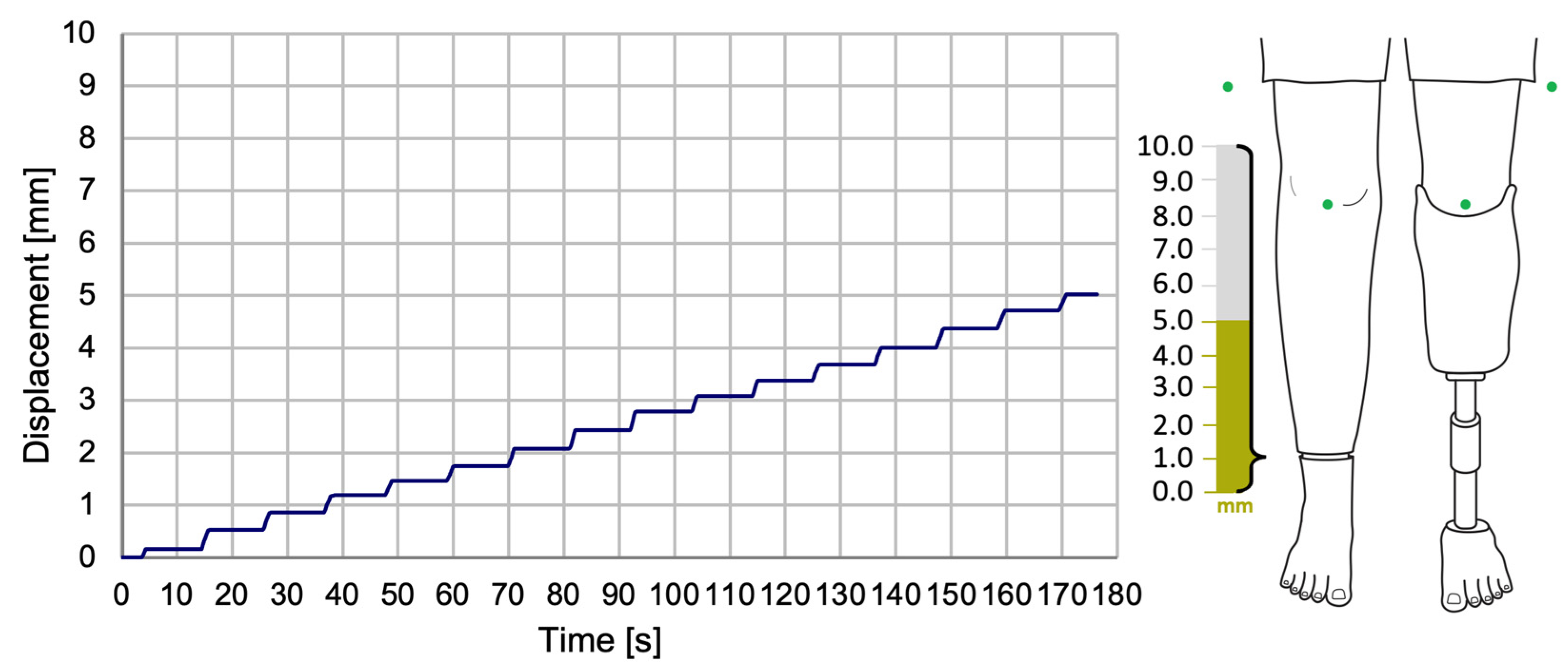
The displacement data demonstrated a gradual approach to the target value (simulated LLD) through a series of incremental steps, with each step corresponding to an approximate displacement of 0.4–0.5 mm, as illustrated in Figure 12.

Figure 12.
The variation of SATP displacement during the compensation of a 5 mm LLD.
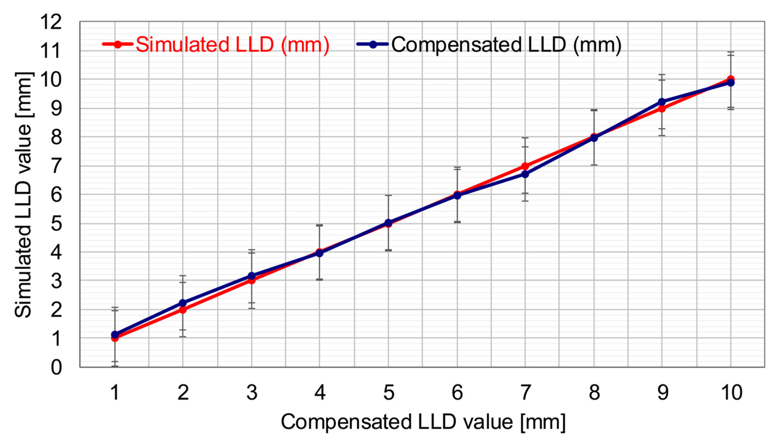
In Figure 13, the red curve depicts the variation of simulated lower limb length discrepancy values within the 1–10 mm range. This figure is a centralized graphical representation.
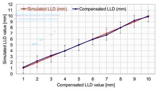
Figure 13.
SATP’s ability to compensate for different LLD values via computer vision.
The duration of the compensation procedure was found to be approximately 45 s for a 1 mm discrepancy (see Figure 11) and 180 s for a 5 mm discrepancy (see Figure 12). These findings serve to highlight the dependence on the magnitude of the LLD.
The second curve, illustrated in blue, demonstrates the SATP’s automated compensation for the simulated LLD values, utilizing the computer vision-based method. This facilitates a direct visual comparison between the manually induced LLD at the experimental stand and the adaptive prosthesis’s ability to restore symmetry to the anatomically shaped mannequin by automatically compensating for the LLD. The relative error associated with the SATP’s correction of this imbalance is 2.44%, corresponding to a mean absolute error of 0.134 mm based on the set of test cases.
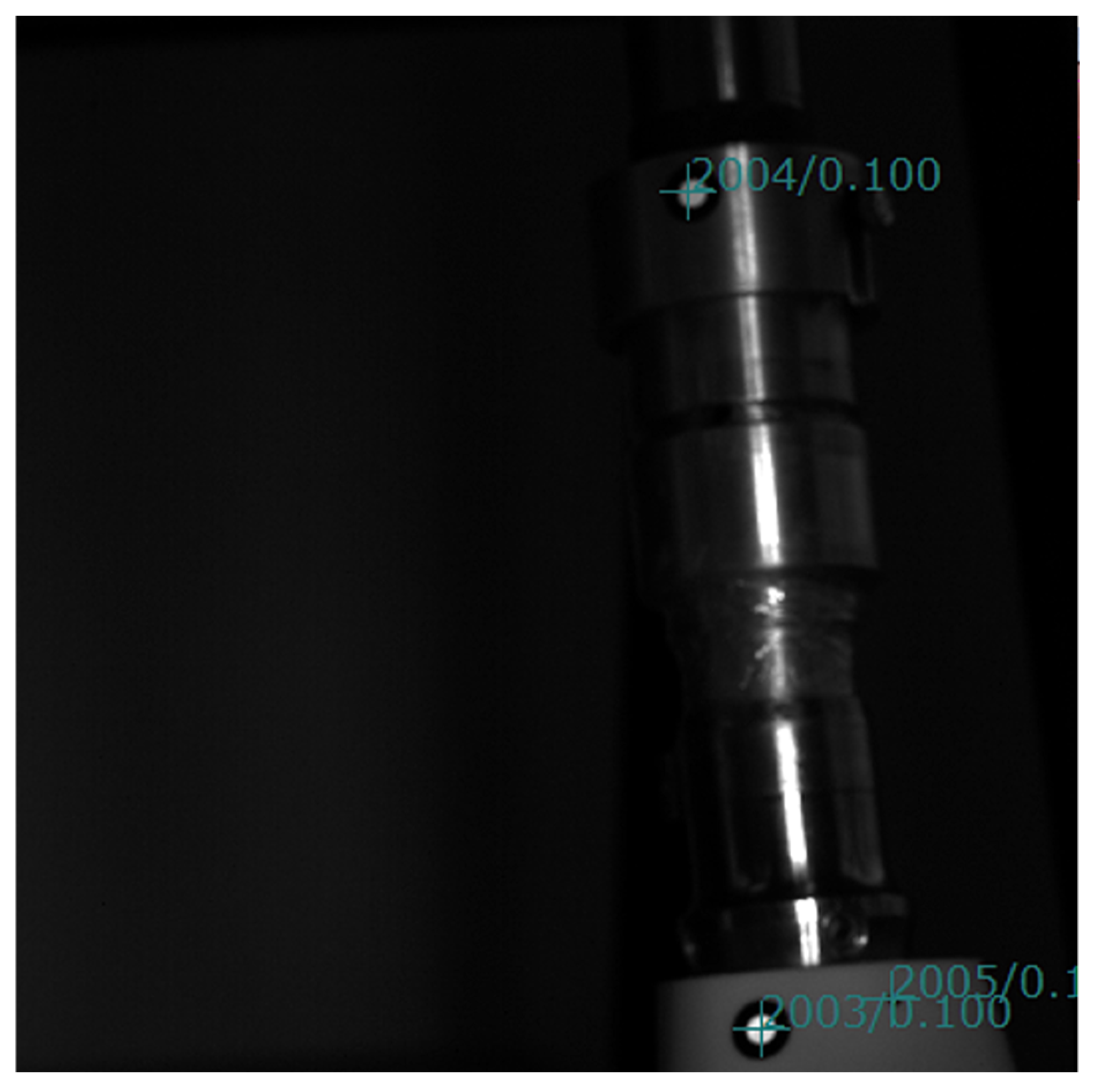
For the complex measurements requiring high precision and detailed analysis of the EPM movements, a high-performance system based on Digital Image Correlation (DIC)—the ARAMIS 3D DIC System, Teledyne Dalsa 12M (Carl Zeiss, Jena, Germany), managed by the PONTOS software, version 6.3.1-1 (PONTOS Software GmbH, Jena, Germany)—was utilized. Following calibration of the experimental setup using this system, the 3D coordinates of two reflective markers monitored by a set of high-performance cameras were obtained. The first marker was positioned on the movable assembly of the EPM, and the second on the prosthetic foot, as illustrated in Figure 14.

Figure 14.
View during EPM testing in the PONTOS software v. 6.3.1-1 (the upper marker: P1).
Subsequent to receiving the command from the control unit (CU), the EPM underwent a modification in length, thereby inducing a change in the prosthetic lower limb’s initial state. The displacement was monitored by calculating the initial 3D coordinates and comparing them with the final 3D coordinates after the EPM movement had been completed.
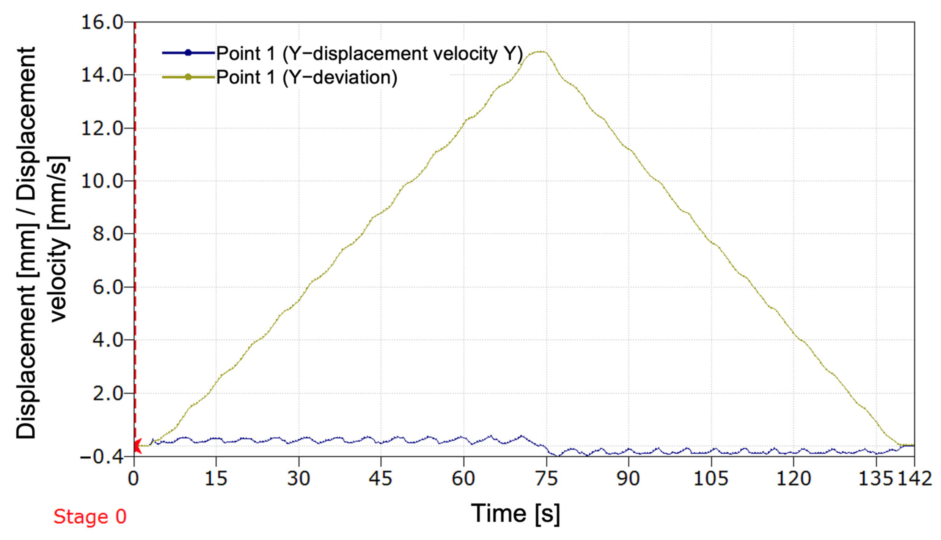
In Figure 15, the graph illustrates the variation in displacement and velocity along the Y-axis for point 1 (P1) during one prosthesis cycle. Initially, the prosthesis is in the reference position, without any displacement (Stage 0). Subsequent activation of the compensation mechanism, executed in a meticulous manner, instigates an incremental rise in displacement, culminating at a maximum value of approximately 15 mm. This marks the prosthesis’s attainment of the predetermined stroke limit. Subsequently, the displacement undergoes a gradual decrease, and the prosthesis reverts to its initial position, thereby completing a full movement cycle.
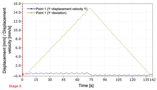
Figure 15.
Variation of displacement and velocity along the Y-axis for P1 during a programmed stroke with return to the initial position.
The displacement velocity, illustrated by the blue curve in Figure 15, maintains a proximity to zero for the majority of the movement, thereby indicating a controlled dynamic. At the initiation of the stroke, the velocity undergoes a gradual increase, reaching a maximum that corresponds to the acceleration phase. As the prosthesis approaches its maximum displacement, a gradual decrease in speed is observed. During the return phase, the speed displays symmetrical behavior, thereby confirming that the prosthesis movement is balanced and stable.
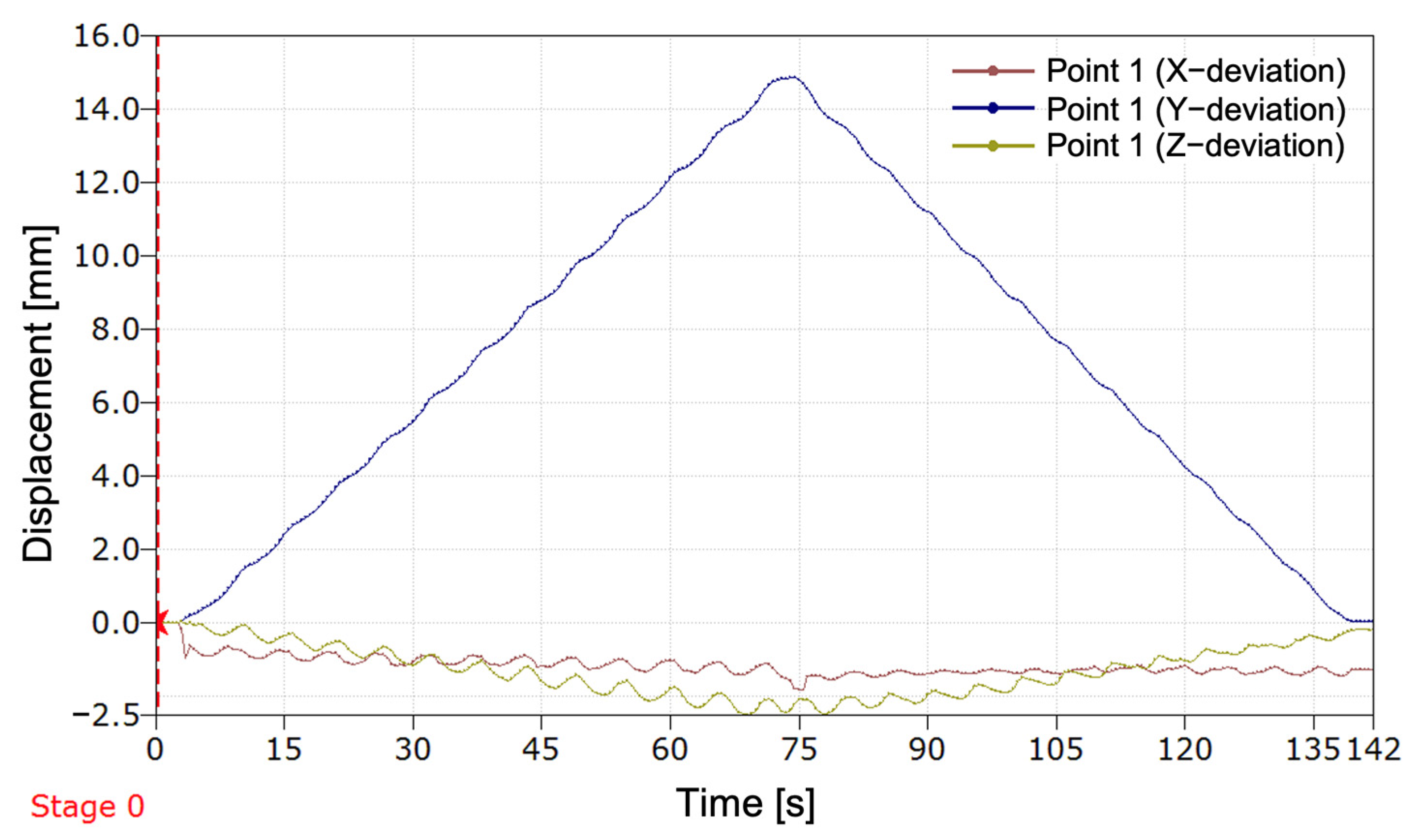
As illustrated in Figure 16, the displacement of P1 was measured during the tests on the three axes: X, Y, and Z. The curve for the Y-axis illustrates the movements performed by the EPM for adapting the prosthesis length (advancing and retracting/increasing and decreasing the length for the programmed stroke). The X-axis indicates a minor misalignment of the movable component relative to the fixed component of the EPM, while the Z-axis highlights any play in the mechanism caused by the shock of coupling the actuator to the rotation, particularly in the area of the elastic bushing that facilitates the connection with the EPM axis.
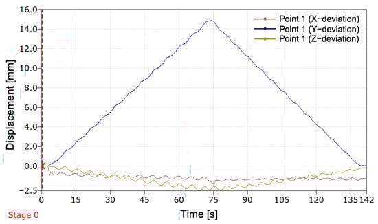
Figure 16.
Variation of displacement along the X-, Y-, and Z-axes for P1 during a programmed stroke with return to the initial position.
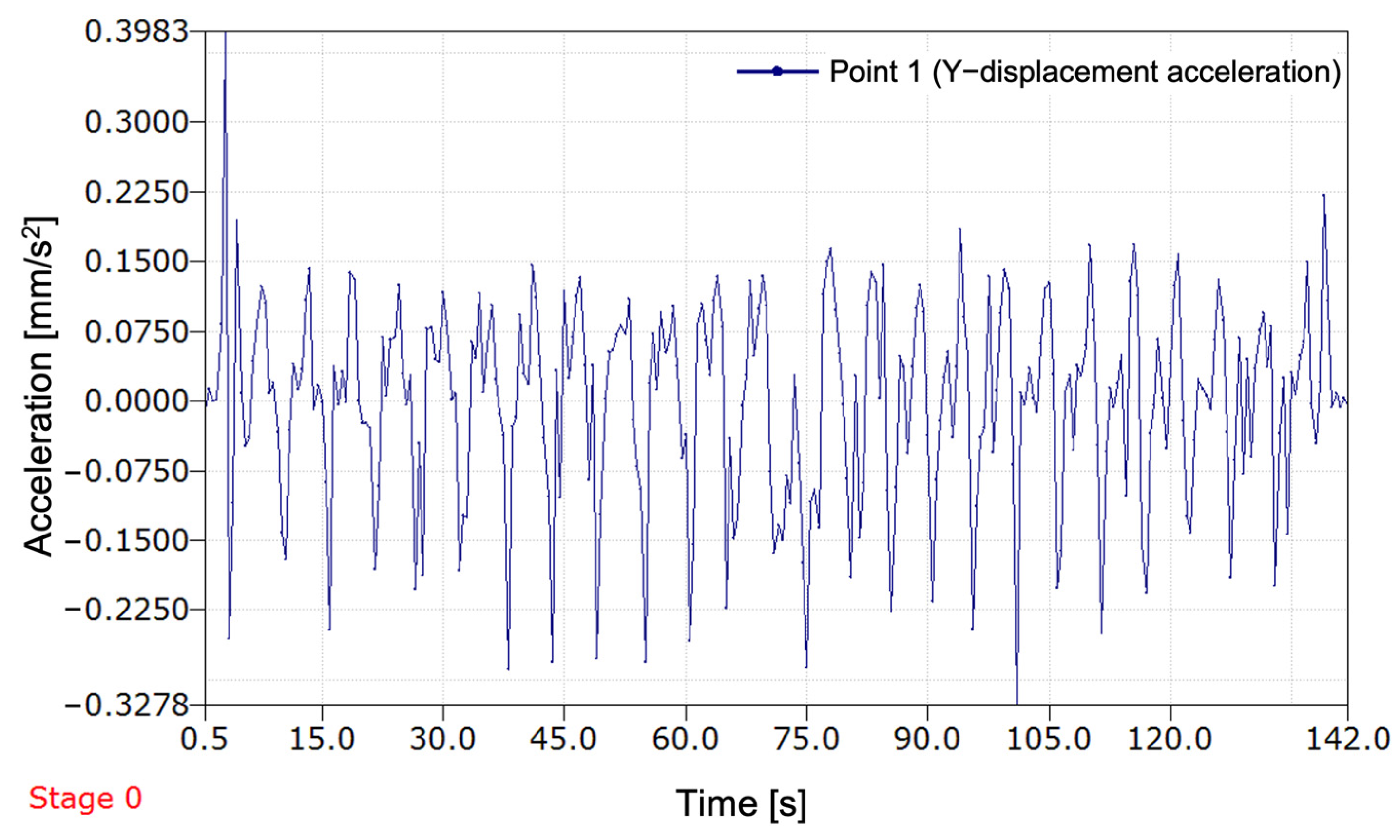
As illustrated in Figure 17, the displacement–acceleration on the Y-axis of P1 from the EPM during the prosthesis’s advance cycle (extension) and retraction cycle (shortening) is demonstrated. Upon initiation of the recording, a significant peak in acceleration is observed, indicative of the system’s startup effect. This is followed by relatively stable oscillation. Throughout the entire measured period, the acceleration oscillates frequently between positive and negative values, corresponding to the rotation of the threaded axis driven by the actuator. The acceleration values remain relatively modest, falling below 0.4 mm/s2, suggesting precise control over the movement. The oscillations are not perfectly uniform, with both their frequency and amplitude varying over time. This phenomenon can be attributed to the active adaptation of the system.
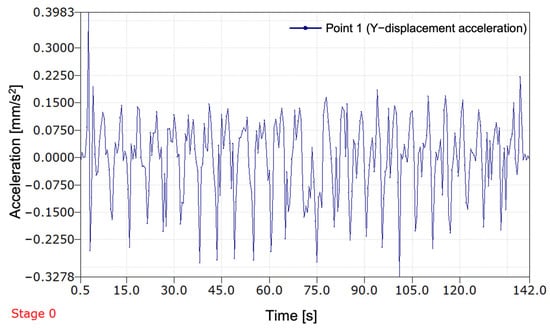
Figure 17.
Evolution of the EPM acceleration along the Y-axis during a programmed stroke (advance and retreat).
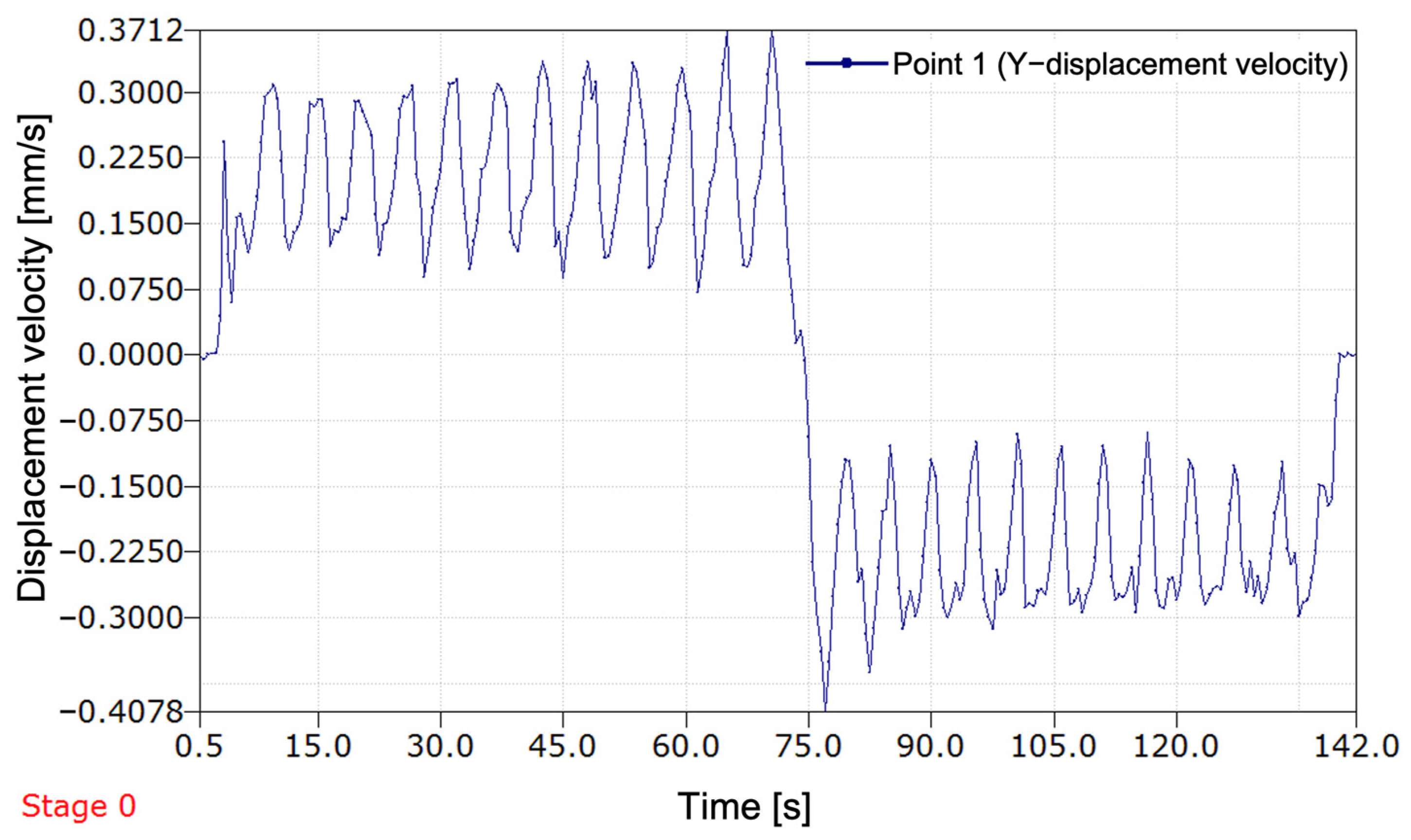
As illustrated in Figure 18, the displacement speed of P1 mounted on the EPM is represented. The recording was performed during a programmed stroke of the actuator, highlighting two distinct stages: first, the advance (extension of the prosthesis), followed by retraction (shortening of the prosthesis). As illustrated by the initial segment of the graph, there is a progressive increase in speed, which ultimately attains a stable oscillatory regime at approximately 0.3 mm per second. These oscillations are attributed to the rotation of the threaded axis driven by the actuator, thereby reflecting the controlled movement of the prosthesis. At approximately 75 s, a sudden transition is observed, marked by a rapid decrease in speed, followed by a reversal of the direction of displacement.

Figure 18.
Evolution of the displacement speed of P1 during a programmed stroke (advance and retreat).
In the subsequent segment of the graph, the velocity assumes a negative value, denoting the initiation of the retraction phase of the prosthesis. The oscillations persist, though their amplitude differs from that of the initial phase, suggesting potential variations in the forces exerted on the system during this phase.
As the graph approaches its conclusion, a renewed increase in speed is observed, indicating the prosthesis’s cessation of movement. This, in turn, signifies the return of the EPM to its original position. This increase is attributed to the progressive deceleration of the mechanism prior to the complete stop, a standard occurrence in the operation of electrically driven devices. The prosthesis follows a controlled motion cycle; however, the speed oscillations during a full stroke could affect the accuracy and stability of the system.
4. Discussion
The findings derived from the implementation of the initial method for compensating for leg length discrepancy (LLD) employing computer vision integrated into a smartphone, with a transtibial prosthesis serving as the effector, substantiate the viability of the adopted approach in restoring the user’s body symmetry. The method’s applicability extends to two distinct patient populations: those who have undergone unilateral amputation and are initially using a temporary transtibial prosthesis, and those in the growth phase.
In comparison with conventional LLD assessment methods that depend on medical imaging (most often X-rays or ultrasound) [8,9,16], functional evaluations (e.g., plantar analysis using baropodometric platforms) performed by specialists [11,13], or automated assessments utilizing a dedicated Master–Slave system [24], our proposed solution is based on a rapid, non-invasive method with a brief patient preparation time. It is both financially and technically accessible, as nearly everyone today owns a smartphone. These considerations ensure a high potential for at-home implementation of the developed and tested method. The primary advantage of this approach lies in its use of a common device—a smartphone—thereby eliminating the need for expensive equipment.
It has been demonstrated by preceding studies that contemporary clinical methodologies are accurate. Nevertheless, these methodologies necessitate specialized equipment and access to qualified medical personnel.
Moreover, extant LLD compensation solutions are passive, lacking automation, and requiring regular manual adjustments [22,25,26,27,28,29,30,31,32,33]. For instance, certain prosthetic rods are engineered to permit length modification with an extension of up to 50 mm, in 1 mm increments, secured with a counter nut [31]. Another variant of an artificial lower limb enables length adjustment from 12.7 cm to 20.3 cm [28]. Additionally, Ottobock offers an adjustable prosthetic rod that allows for manual modification of prosthesis length [29]. As documented in the scientific literature, the extant solutions offer a range of length adjustment capabilities. However, these devices do not incorporate automated or semi-automated adjustment methods and necessitate the presence of a medical specialist to perform the modifications. Despite the substantial advancements in lower limb prostheses in recent years, from conventional systems to intelligent prosthetic systems managed by artificial intelligence (AI), allowing adaptability to various user interactions or environments, such as joint control through AI algorithms [40] or prostheses that can interpret electromyographic (EMG) signals from the patient to facilitate control during gait phases [41], AI remains underutilized for control of lower limb prostheses. However, the extant literature mentions applications of machine learning for fall detection in amputees and for managing the temperature within the prosthetic socket [42]. Recently, advanced methods for human gait pattern recognition have been proposed, with applications in sports and clinical contexts [43]. However, such complex systems do not provide a dedicated technical solution for correcting LLD in children with unilateral transtibial amputation, where a practical, adaptable, and accessible approach is required. Furthermore, a review of the specialized literature reveals a paucity of reports on lower limb prostheses that exhibit the capacity for automatic adaptation to the amputee’s body conformation. This approach, in comparison to the previously described solutions, is characterized by its simplicity, feasibility at low cost, and the ability to maintain body symmetry without necessitating frequent visits to the prosthetist. The proposed system integrates the benefits of image-based digital methods [11,13,14,15,16,17,18,19,20,21] with the ease of use of a smartphone, which is connected to a transtibial prosthesis. This innovative and accessible approach to automatic LLD compensation represents a substantial advancement in the field.
The experimental results revealed the progression of the SATP process for automatic compensation of simulated LLD. It was observed that the SATP exhibited an incremental compensation pattern, reflecting the prosthesis’s response to the detection of leg length discrepancy. The consistent compensation rate indicates a stable automatic control system, allowing for rapid assessment of LLD and gradual restoration of body alignment, without inducing abrupt variations, unwanted oscillations, or significant overcompensation.
The results obtained from the present study demonstrate that the implementation of this compensation method has the potential to ensure the maintenance of an appropriately sized prosthesis over an extended period, particularly in cases involving growing children. Additionally, its application in patients utilizing temporary prostheses following amputation could facilitate adjustment to a prosthesis of the correct size. It is imperative to acknowledge the significance of this aspect in the prevention of limb length discrepancies and the subsequent secondary conditions that may arise.
The system was evaluated using 1000 frames recorded under strictly controlled laboratory conditions, with constant indoor lighting and fixed camera placement. In this environment, the system correctly identified alignment in 94.6% of frames. The maximum observed angular deviations from the calibrated baselines were: Δθ_middle = 2.814°, Δθ_upper = 1.888°
Frames exceeding the calibrated tolerances (±0.073° for the middle line, ±0.90° for the upper line) were flagged as misaligned, indicating a leg length discrepancy (LLD).
Preliminary occlusion tests showed that the system remained functional with up to 50% of a marker partially blocked, but alignment detection failed when occlusion exceeded this threshold. These results demonstrate the algorithm’s reliability and accuracy under stable, repeatable laboratory conditions.
This study introduced a self-adaptive prosthetic control system that incorporates a vision-based mechanism for detecting and correcting leg length discrepancies (LLD) in real time. The system employs a calibrated, marker-based computer vision algorithm operating on high-resolution video input (3840 × 2160), utilizing HSV color segmentation and centroid-based geometric analysis to extract and evaluate angular relationships between the prosthesis and fixed wall reference markers.
Calibration trials conducted under controlled laboratory conditions established baseline angular references of θ_middle = 161.2° and θ_upper = 108.2°, with corresponding tolerances of ±0.073° and ±0.90°, determined through statistical analysis of 60 aligned frames. The algorithm achieved a correct alignment detection rate of 94.6% across 1000 test frames, with maximum observed deviations of 2.81° and 1.88° for the middle and upper lines, respectively. Additional tests confirmed stable performance while occlusion resistance was maintained up to 50% marker coverage.
In the present study, the proposed SATP correction system achieved a mean absolute error of 0.134 mm, calculated based on the test case set, with a maximum individual error of 0.28 mm. These values are significantly below the lowest clinically relevant threshold for LLD (i.e., 5 mm), which is generally considered the lower limit at which long-term complications may begin to appear [4,7,8]. Consequently, the correction accuracy achieved by the SATP system demonstrates high precision and remains well within the clinically acceptable range, even for mild discrepancies. These results support the feasibility of integrating SATP into clinical practice as a preventive and compensatory solution for LLD.
Furthermore, the system has the potential to reduce the frequency of visits to the prosthetist, as minor adjustments can be made automatically, thereby eliminating the need for frequent professional intervention.
Despite the system’s notable advantages, it is imperative to acknowledge potential limitations that must be taken into account. The precision of LLD evaluation is contingent upon the quality of the captured image, which is susceptible to external factors such as lighting conditions or the resolution of the smartphone camera. A further limitation is that the current solution is optimized for users with transtibial amputations and would require adaptations for other types of prostheses. In future research, we aim to address the impact of lighting conditions on the algorithm and extend the correction method to other amputated anatomical segments.
Future research will address the impact of lighting conditions on the algorithm and extend the correction method to other amputated anatomical segments. The goal is to simplify the system by reducing the number of markers and minimize environmental errors to reduce error accumulation over time. Additionally, we will evaluate the adjustment frequency during clinical trials in collaboration with medical specialists.
At this experimental stage, validation was carried out on a mannequin in a static and controlled environment. The aim was to demonstrate the technical feasibility of the proposed method for correcting a simulated LLD. While this approach does not fully replicate the biomechanical complexity of a real human user, it enabled an initial evaluation of the system’s accuracy and the operating principle of the SATP. However, this approach falls short in fully capturing the intricate biomechanical nuances inherent in real-world applications. The limitations of static testing will be addressed in subsequent research phases, which will include clinical studies and dynamic testing on human users.
The proposed method in this study offers a novel approach to the assessment of and compensation for LLD in transtibial amputee patients by leveraging accessible technologies. Notwithstanding the challenges associated with optimization for enhanced accuracy, the proposed solution offers considerable potential for clinical implementation, with the potential to reduce the necessity for manual adjustments and contribute to an enhancement in the quality of life of patients.
5. Conclusions
The present study constitutes an investigation into the development of a methodology for the correction of leg length discrepancy (LLD). The method was grounded in the field of computer vision and integrated into a self-adaptive temporary transtibial prosthesis. The system was developed for patients who have undergone transtibial amputation and are undergoing medical rehabilitation. During this process, the residual limb is shaped to adapt to the needs of the individual patient. It is also suitable for children whose limb length discrepancies may change frequently over time.
These results demonstrate that the proposed approach offers reliable, precise, and computationally efficient alignment monitoring, supporting its integration into closed-loop control for prosthetic systems in structured clinical or home environments.
The proposed system utilizes a smartphone application, an accessible and familiar device for most users, which also ensures a very short preparation time. The development process entailed the creation of a computer vision-based LLD compensation application and the construction of an experimental setup for laboratory testing of the prototype.
The experimental results obtained from this study confirm the feasibility and functionality of the initial computer vision-based automatic LLD compensation method, which is managed via a smartphone and integrated into a transtibial prosthesis.
Subsequent research will concentrate on clinical trials, encompassing transtibial amputees and a range of cases, with a view to evaluating the efficacy and long-term usability of the system. Furthermore, the expansion of the adaptability of the system to other types of prostheses, in addition to the optimization of the algorithm for real-time performance, will increase the practical applicability of this method.
6. Patents
Patent applications no. A00055—16 February 2024, and no. A00381—28 June 2024, State Office for Inventions and Trademarks, Romania.
Author Contributions
Conceptualization, D.C.F. and N.E.S.; methodology, D.C.F., O.Z., N.E.S. and V.I.M.; software, O.Z., V.I.M., Ș.D.A. and D.C.F.; validation, N.E.S. and V.I.M.; formal analysis, O.Z. and D.C.F.; investigation, O.Z. and D.C.F.; writing—original draft preparation, D.C.F. and O.Z.; writing—review and editing, O.Z., N.E.S., V.I.M., D.C.F., D.F.C. and A.M.; visualization, N.E.S., V.I.M. and O.Z.; supervision, N.E.S. and V.I.M.; project administration, D.C.F., O.Z., A.M., D.F.C. and N.E.S. All authors have read and agreed to the published version of the manuscript.
Funding
This work was supported by the “National Research Grants—ARUT” program of the Technical University “Gheorghe Asachi” of Iasi, Romania, founding number GnaC2023_269, Founder: Technical University “Gheorghe Asachi” of Iasi, Romania.
Institutional Review Board Statement
Not applicable.
Informed Consent Statement
Not applicable.
Data Availability Statement
The data presented in this study are available on request from the corresponding author. The data are not publicly available due to privacy restrictions.
Acknowledgments
This research paper was supported by Boosting Ingenium for Excellence (BI4E) project, funded by the European Union’s HORIZON-WIDERA-2021-ACCESS-05-01-European Excellence Initiative under the Grant Agreement No. 101071321.

Conflicts of Interest
The authors declare no conflicts of interest.
Abbreviations
The following abbreviations are used in this manuscript:
| CoM | Center of mass |
| CV | Computer vision |
| ECU | Electronic control unit |
| EPM | Extensible prosthetic module |
| IMM | Idea mapping method |
| LLD | Leg length discrepancy |
| SATP | Self-adaptive transtibial prosthesis |
References
- Shi, Q.-Q.; Yick, K.-L.; Li, C.-H.; Tse, C.-Y.; Hui, C.-H. Biomechanical Evaluation of Elliptical Leaf Spring Prosthetics for Unilateral Transtibial Amputees During Dynamic Activities. Technologies 2025, 13, 129. [Google Scholar] [CrossRef]
- Yurova, V.A.; Velikoborets, G.; Vladyko, A. Design and Implementation of an Anthropomorphic Robotic Arm Prosthesis. Technologies 2022, 10, 103. [Google Scholar] [CrossRef]
- Ayvali, M.; Wickenkamp, I.; Ehrmann, A. Design, Construction and Tests of a Low-Cost Myoelectric Thumb. Technologies 2021, 9, 63. [Google Scholar] [CrossRef]
- Applebaum, A.; Nessim, A.; Cho, W. Overview and Spinal Implications of Leg Length Discrepancy: Narrative Review. Clin. Orthop. Surg. 2021, 13, 127. [Google Scholar] [CrossRef] [PubMed]
- Khamis, S.; Danino, B.; Springer, S.; Ovadia, D.; Carmeli, E. Detecting Anatomical Leg Length Discrepancy Using the Plug-in-Gait Model. Appl. Sci. 2017, 7, 926. [Google Scholar] [CrossRef]
- Woerman, A.L.; Binder-Macleod, S.A. Leg Length Discrepancy Assessment: Accuracy and Precision in Five Clinical Methods of Evaluation. J. Orthop. Sports Phys. Ther. 1984, 5, 230–239. [Google Scholar] [CrossRef] [PubMed]
- Gordon, J.E.; Davis, L.E. Leg Length Discrepancy: The Natural History (And What Do We Really Know). J. Pediatr. Orthop. 2019, 39, S10–S13. [Google Scholar] [CrossRef] [PubMed]
- Khamis, S.; Danino, B.; Ovadia, D.; Carmeli, E. Correlation between Gait Asymmetry and Leg Length Discrepancy—What Is the Role of Clinical Abnormalities? Appl. Sci. 2018, 8, 1979. [Google Scholar] [CrossRef]
- Lee, R.Y.; Turner-Smith, A. The influence of the length of lower-limb prosthesis on spinal kinematics. Arch. Phys. Med. Rehabil. 2003, 84, 1357–1362. [Google Scholar] [CrossRef] [PubMed]
- Sabharwal, S.; Kumar, A. Methods for Assessing Leg Length Discrepancy. Clin. Orthop. Relat. Res. 2008, 466, 2910–2922. [Google Scholar] [CrossRef] [PubMed]
- Vrhovski, Z.; Obrovac, K.; Nižetić, J.; Mutka, A.; Klobučar, H.; Bogdan, S. System for Evaluation and Compensation of Leg Length Discrepancy for Human Body Balancing. Appl. Sci. 2019, 9, 2504. [Google Scholar] [CrossRef]
- Fodor, D.C.; Chitariu, D.F.; Seghedin, N.E. Testing a New Concept of a Self-Adaptive Transtibial Prosthesis. Bull. Polytech. Inst. Iași. Mach. Constr. Sect. 2023, 69, 123–131. [Google Scholar] [CrossRef]
- Vrhovski, Z.; Obrovac, K.; Mutka, A.; Bogdan, S. Design, modeling and control of a system for dynamic measuring of leg length discrepancy. In Proceedings of the 2017 21st International Conference on System Theory, Control and Computing ICSTCC, Sinaia, Romania, 19–21 October 2017; IEEE: Piscataway, NY, USA, 2017. [Google Scholar] [CrossRef]
- Abu-Faraj, Z.O.; Abdul-Al, M.M.; Al-Deeb, R.A. Leg length discrepancy: A study on in-shoe plantar pressure distribution. In Proceedings of the 2015 8th International Conference on Biomedical Engineering and Informatics BMEI, Shenyang, China, 14–16 October 2015; IEEE: Piscataway, NY, USA, 2015. [Google Scholar] [CrossRef]
- Salekzamani, Y.; Abolghassemi Fakhree, N.; Ebrahimi, A.; Heravi, H.; Dolatkhah, N. Motorized Leg Length Discrepancy Measure: A New Device for Clinical Use—A Cross-sectional Study. Crescent J. Med. Biol. Sci. 2022, 9, 161–167. [Google Scholar] [CrossRef]
- Rannisto, S.; Paalanne, N.; Rannisto, P.-H.; Haapanen, A.; Oksaoja, S.; Uitti, J.; Karppinen, J. Measurement of leg-length discrepancy using laser-based ultrasound method. Acta Radiol. 2011, 52, 1143–1146. [Google Scholar] [CrossRef] [PubMed]
- Zheng, Q.; Shellikeri, S.; Huang, H.; Hwang, M.; Sze, R.W. Deep Learning Measurement of Leg Length Discrepancy in Children Based on Radiographs. Radiology 2020, 296, 152–158. [Google Scholar] [CrossRef] [PubMed]
- Paravastu, S.; Paravastu, R.S.; Srivatsan, K.H. System, Device, and Method of Determining Anisomelia or Leg Length Discrepancy (LLD) of a Subject by Using Image Analysis and Machine Learning. U.S. Patent US2023080723A1, 16 March 2023. [Google Scholar]
- Tone, S.; Hasegawa, M.; Naito, Y.; Wakabayashi, H.; Sudo, A. Accuracy of image-free navigation in intraoperative leg length change from total hip arthroplasty using evaluations from 2D and 3D measurements. BMC Musculoskelet. Disord. 2021, 22, 1021. [Google Scholar] [CrossRef] [PubMed]
- Zvorişteanu, O.; Fodor, D.C.; Manta, V.I.; Seghedin, N.E.; Achirei, Ş.D.; Chitariu, D.F. A Computer Vision-Based Solution for Assessing Prosthetic Leg Length Discrepancy. In Proceedings of the 2024 E-Health and Bioengineering Conference (EHB), IASI, Romania, 14–15 November 2024; IEEE: Piscataway, NY, USA, 2024; pp. 1–4. [Google Scholar] [CrossRef]
- Griffet, J. Amputation and prosthesis fitting in paediatric patients. Orthop. Traumatol. Surg. Res. 2016, 102, S161–S175. [Google Scholar] [CrossRef] [PubMed]
- Muilenburg, T.B. Prosthetics for Pediatric and Adolescent Amputees. In Cancer Treatment and Research; Springer: Boston, MA, USA, 2009; pp. 395–420. [Google Scholar] [CrossRef]
- Gholizadeh, H.; Baddour, N.; Dudek, N.; Lemaire, E.D. A New Temporary Training Prosthesis for People with Transtibial Amputation: A Technical Note. Can. Prosthet. Orthot. J. 2024, 7, 43034. [Google Scholar] [CrossRef] [PubMed]
- Fodor, D.C.; Chitariu, D.F.; Aghion, C.; Seghedin, N.E. Self-Adaptive Transtibial Prosthesis: Automatic Detection and Compensation of Leg Length Discrepancy. Appl. Sci. 2025, 15, 3247. [Google Scholar] [CrossRef]
- Van der Riet, D.; Stopforth, R. A low cost, extendable prosthetic leg for trans-fermoral amputees. In Mechatronics: Principles, Technologies and Applications; Nova Science Publishers: Hauppauge, NY, USA, 2015; Chapter 6. [Google Scholar]
- Thurkal, C. This Prosthetic Leg Grows with Your Child! 2021. Available online: https://www.yankodesign.com/2021/01/21/this-prosthetic-leg-grows-with-your-child/ (accessed on 2 April 2025).
- Turner, T. Fit for Everyone, Yanko Design. 2013. Available online: https://www.yankodesign.com/2013/07/17/fit-for-everyone/ (accessed on 2 April 2025).
- Swingen, M.L. CU Boulder Students Design Adjustable Leg Prosthetic for Growing Kids. Available online: https://www.colorado.edu/mechanical/2023/05/01/cu-boulder-students-design-adjustable-leg-prosthetic-growing-kids (accessed on 2 April 2025).
- Ottobock. Tube Adapter, Short, Length Adjustable. Available online: https://shop.ottobock.ca/en/Prosthetics/Lower-Limb-Prosthetics/Adapters-Structural-Components/Tube-Adapter%2C-short%2C-length-adjustable/p/2R45%7E534 (accessed on 2 April 2025).
- Kadhim, F.M.; Jaber Jweeg, M.; Yousuf Al-Kkow, R.N.; Al-Din Tahir, M.S. Design of adjustable prosthetic pylon for children amputees: Numerical analysis case study. Int. Rev. Appl. Sci. Eng. 2023, 14, 349–357. [Google Scholar] [CrossRef]
- Padhi, J.K.; Swain, P.; Madhusmita Das, C. Development of an Adjustable Pylon for Lower Limb Prosthesis: A Prototype. Int. J. Health Sci. Res. 2022, 12, 120–123. [Google Scholar] [CrossRef]
- Chen, G. Artificial Limb with Adjustable Height. CN201085704Y, 21 October 2007. [Google Scholar]
- Lenka, P.K.; Chowdhury, A.R.; Kumar, R. Design Development of Lower Extremity Paediatric Prosthesis, a Requirement in Developing Countries. Int. J. Pharm. Med. Res. 2008, 19, 8–12. [Google Scholar]
- TTMotor. G.M.2.5.-3.7.0.C.A. Available online: https://p.globalsources.com/IMAGES/PDT/SPEC/301/K1123392301.pdf (accessed on 26 March 2025).
- Handson Technology. L298N Dual H-Bridge Motor Driver. Available online: http://www.handsontec.com/dataspecs/L298N%20Motor%20Driver.pdf (accessed on 26 March 2025).
- User Manual for L298N Motor Driver Board (ST1112). Available online: https://asset.conrad.com/media10/add/160267/c1/-/en/001525437ML01/upute-za-rukovanje-1525437-iduino-st-1112-pogon-za-motor-1-st.pdf (accessed on 26 March 2025).
- Arduino. Arduino Nano. Available online: https://store.arduino.cc/products/arduino-nano (accessed on 26 March 2025).
- Mitutoyo. User’s Manual USB-ITPAK. MiCAT—Mitutoyo Intelligent Computer Aided Technology Measurelink. No. 99MAM024A. Ver. 2.000. First Edition, March 2013. Available online: http://www.mitutoyo.co.jp/global.html (accessed on 14 May 2025).
- Mitutoyo. Absolute Solar Digimatic Indicator ID-S—Datasheet. Available online: https://docs.rs-online.com/79a1/0900766b81365676.pdf (accessed on 14 May 2025).
- Chopra, S.; Emran, T.B. Advances in AI-based prosthetics development: Editorial. Int. J. Surg. 2024, 110, 4538–4542. [Google Scholar] [CrossRef] [PubMed]
- Geethanjana, H.K.A.; Hettige, B. Application of Artificial Intelligence in Prosthetics: A Review. Conference Paper. Available online: https://ir.kdu.ac.lk/bitstream/handle/345/7432/FOC_IRC2023_Proceeding-Book-343-348.pdf?sequence=1&isAllowed=y (accessed on 10 July 2025).
- Choo, Y.J.; Chang, M.C. Use of machine learning in the field of prosthetics and orthotics: A systematic narrative review. Prosthet. Orthot. Int. 2023, 47, 226–240. [Google Scholar] [CrossRef] [PubMed]
- Xu, D.; Zhou, H.; Quan, W.; Jiang, X.; Liang, M.; Li, S.; Ugbolue, U.C.; Baker, J.S.; Gusztav, F.; Ma, X.; et al. A new method proposed for realizing human gait pattern recognition: Inspirations for the application of sports and clinical gait analysis. Gait Posture 2024, 107, 293–305. [Google Scholar] [CrossRef] [PubMed]


Disclaimer/Publisher’s Note: The statements, opinions and data contained in all publications are solely those of the individual author(s) and contributor(s) and not of MDPI and/or the editor(s). MDPI and/or the editor(s) disclaim responsibility for any injury to people or property resulting from any ideas, methods, instructions or products referred to in the content. |
© 2025 by the authors. Licensee MDPI, Basel, Switzerland. This article is an open access article distributed under the terms and conditions of the Creative Commons Attribution (CC BY) license (https://creativecommons.org/licenses/by/4.0/).