Article

Modeling and Efficiency Analysis of an Immersed Heat Exchanger for Solar-Powered Industrial Heat Processes: A Case Study on Wool Washing

1
Centre de Développement des Energies Renouvelables, BP. 62 Route de l’Observatoire Bouzareah, Alger 16340, Algeria
2
Département de Génie Mécanique, Laboratoire de Biomécanique Appliquée et Biomatériaux (LABAB), Ecole Nationale Polytechnique d’Oran—Maurice Audin, BP 1523 El Mnaour, Oran 31000, Algeria
3
University MARITIMA of Constanta, 900663 Constanta, Romania
*
Author to whom correspondence should be addressed.
Technologies 2025, 13(7), 308; https://doi.org/10.3390/technologies13070308
Submission received: 10 April 2025 / Revised: 20 June 2025 / Accepted: 14 July 2025 / Published: 17 July 2025

Abstract

Efficient water heating is essential for wool-washing processes, which demand temperatures above 70 °C. To meet this requirement sustainably, a parabolic trough solar concentrator system is proposed in this paper as an alternative to conventional natural gas systems. The design centers on a water pool constructed from bricks reinforced with an internal steel layer, enhancing heat exchange efficiency. Also, various synthetic oils were analyzed as heat transfer fluids (HTFs) within an immersed heat exchanger, such as Thermia B oil, Heat Transfer Oil 32, biphasic oil, and Therminol vp1 oil. Numerical simulations were performed using ANSYS CFX v19.2 software with the k-ε turbulence model to evaluate the thermal performance and temperature distribution. The results demonstrate the superior efficiency of the solar-powered system, with the steel-reinforced pool achieving optimal water temperatures between 78 °C and 85 °C, exceeding the required threshold for industrial wool washing. Among the various synthetic oils analyzed, Thermia B emerged as the most effective heat transfer fluid, maintaining water temperatures in the range of 75 °C to 85 °C. This superior thermal performance is attributed to its high thermal conductivity and reduced heat loss, ensuring consistent and optimal heat distribution for the wool-washing process.

1. Introduction

The textile industry, particularly in the context of wool transformation, holds a critical place in light manufacturing. Wool processing involves several key stages, with washing representing one of the most decisive phases. The quality of the final wool product is determined during this stage. Among the prevalent methods employed, water pool-based washing is widely used. However, this method is highly resource-intensive, especially in terms of water consumption and thermal energy demand. The environmental impact is further amplified by effluents—primarily organic in origin—that contribute significantly to the pollution load in industrial wastewater. Additionally, the dependence on fossil fuels for heating renders the process both energy-inefficient and environmentally unsustainable. As a result, European environmental regulations enforce strict controls on facilities processing more than 500 kg of wool daily [1].
In response to these challenges, the wool industry is increasingly focused on integrating sustainable practices. One critical area of focus is reducing the carbon emissions associated with wet processing. Vade. A et al. performed a life cycle-based analysis and reported that this stage contributes roughly 0.031 t CO2e per unit of production, with coal as the largest emitter at 0.066 t CO2e/product. Conversely, cleaner energy inputs like biomass and pressurized natural gas were found to have substantially lower emissions. Their findings underscore the urgency of adopting low-emission energy systems to reduce the sector’s environmental footprint. Efforts to make wool a more sustainable material throughout its life cycle are also underway [1]. Popescu. C et al. presented a comprehensive review positioning wool as a biodegradable and functional alternative to synthetic polymers. The study explored modern innovations such as enzyme-based treatments and natural dyeing while emphasizing the need for environmentally responsible sheep husbandry and broader regulatory support within the EU [2]. Russell M.I et al. offer a comprehensive review of wool as a modern textile fiber, focusing on its structural complexity, environmental performance, and evolving role in sustainable textile systems. Using a life cycle assessment (LCA), the study analyzed three Australian Merino wool supply chain scenarios, revealing that biogenic methane from sheep is the primary source of carbon emissions, while garment laundering dominates water and energy use. Although wool is natural and renewable, the paper emphasizes that sustainability must be critically assessed. It highlights the urgent need for better environmental data, especially for textile processing in Asia, and stresses the importance of transparent assumptions in the LCA methodology for guiding meaningful environmental improvements across the wool supply chain. Innovative scouring technologies are central to sustainable wool processing [3]. Czaplicki. Z et al. developed a modified method combining low-energy detergents and ultrasound-assisted scouring. This two-stage process shortened the cleaning time significantly and reduced energy consumption while preserving fiber integrity [4]. Similarly, Iglesias. M.S et al. proposed a biosurfactant–enzyme system that reduces wool felting by 41% without using toxic chemicals. Their approach aligns with organic standards and introduces biosurfactants into wool processing for the first time [5]. Matlhoko. K.S et al. also demonstrated the value of accessible detergent-based scouring methods for small-scale farmers, suggesting practical alternatives where high-tech infrastructure is lacking. Energy use in wool washing has drawn substantial interest, particularly from the standpoint of integrating renewable sources [6]. Further contributions to eco-friendly scouring methods include that of Bhavsar. P et al., who explored two sustainable approaches for wool grease removal: solvent-based extraction using cyclopentyl methyl ether (CPME) and wool protein hydrolysate (WPH) as a biosurfactant. CPME outperformed conventional solvents like hexane and diethyl ether by achieving a 11.95% grease yield while maintaining fiber structure, as confirmed by SEM and FTIR analyses. WPH matched the efficiency of commercial surfactants, reducing residual grease in Sopravissana wool from 22.29% to 0.30% without damaging fiber morphology [7]. Kunik. A et al. proposed a two-stage wool scouring method based on high-energy discrete processing (HDP), followed by cleaning with a customized surfactant (Sulside). This process significantly improved the fiber quality and increased wool grease recovery rate to 96%. The HDP treatment not only enhanced the scouring effect but also reduced felting, offering a robust, scalable solution for industrial wool purification [8]. Dragović. N et al. emphasized that solar, wind, geothermal, and biomass systems can significantly reduce energy consumption and environmental impact across the textile industry. Their analysis identified six key drivers for the successful adoption of renewable energy systems (RESs), including policy incentives and technological innovation [9]. Mokhtar. G et al. validated the thermal efficiency of a Linear Fresnel Reflector (LFR) system designed for water heating in Blida, Algeria. Their simulations matched experimental outcomes and demonstrated efficiencies exceeding 29%, with outlet temperatures suitable for wool scouring [10]. Likewise, Famiglietti. A et al. introduced a solar air heater capable of providing industrial-grade heat in the 300–400 °C range. This system bypasses traditional heat transfer fluids, reducing both maintenance and installation costs [11]. On the commercial scale, Nunayon S.S et al. evaluated a thermosyphon solar water heating system in Nigeria. With efficiency levels reaching 81.5% and with water temperatures up to 78 °C, the study affirmed the economic viability of solar systems for clean water heating in small businesses, with potential applications in the textile and wool industries [12]. Li. D et al. proposed a hybrid solar–ground source heat pump system incorporating latent heat storage. Their solution achieved an overall efficiency of 51.25%, reduced gas use by over 80%, and lowered CO2 emissions by more than 1100 tons per year—marking a significant advancement for fossil-free heat delivery in industrial applications. The optimization of renewable heating technologies continues to evolve [13]. Zhang. T et al. used the Hooke–Jeeves algorithm to optimize a solar-air source heat pump for cold, high-altitude regions. Their multi-objective approach reduced heating costs and energy use while preserving thermal comfort, demonstrating potential adaptability to wool scouring processes under diverse climatic conditions. In parallel, detailed thermal analyses are informing system design [14]. Sekine. M et al. investigated thermal stratification in water pools heated by a vertical rod. Their PIV measurements and CFD models revealed flow dynamics and mixing behavior at various power levels, offering insights for energy-efficient tank designs [15]. Similarly, Singh. S et al. analyzed heat and mass transfer under low-pressure vaporization, showing how vacuum level, superheat, and water depth influence heat transfer coefficients. Their findings support the design of efficient, low-temperature thermal systems in industrial applications [16]. Material design also plays a supporting role. Kazmi. S.M.S et al. studied bricks incorporating sugarcane bagasse ash and rice husk ash, finding that such bricks have excellent insulating properties and reduce thermal conductivity by up to 31%, without compromising structural performance. These materials may be utilized to improve the thermal retention of wool-washing systems and reduce heating losses [17].
This research paper is part of a socio-economic project commissioned by a wool-washing factory, aiming to address the factory’s critical need for hot water at 70 °C, which is essential for its operations. Currently, the factory relies on a conventional boiler to heat water, but the high cost of gas consumption prevents it from reaching the required temperature for a large water pool. The primary objective of this study is to explore the use of a small parabolic trough solar concentrator system, installed on factory rooftops, to generate industrial heat for wool processing. This system is designed to support key operations, including washing wool at approximately 70 °C, by harnessing concentrated solar energy, the project seeks to meet the factory’s thermal needs while reducing its dependence on fossil fuels. Additionally, a storage power system can be integrated using a dedicated tank, accompanied by an electric system to heat the heat transfer fluid. This system includes a circulation pump, valves for switching between charging and discharging modes, and a solenoid valve to optimize and regulate the circulation of the heat transfer fluid. Such a storage solution ensures continuous operation, even during the night or in adverse weather conditions, thereby guaranteeing stable and reliable performance.
This study emphasizes the potential of solar concentrators to improve energy efficiency, contribute to minimizing environmental impacts, and promote sustainability in the wool processing industry. Traditional wool scouring processes, typically involving hot aqueous detergent solutions at 60–65 °C, stand to benefit significantly from this approach, offering a sustainable solution without compromising operational effectiveness. By integrating renewable energy technologies, this research aims to set a benchmark for innovative and eco-friendly practices in the wool processing sector, ensuring reduced CO2 emissions and the preservation of fossil resources for future generations.

2. Materials and Methods

The Materials and Methods Section provides a comprehensive description of the solar-powered system implemented for the wool-washing process, detailing the structural components, operational principles, and thermal management strategies. The focus is on the integration of cylindrical parabolic mirrors, absorber tubes, and a closed-loop heat transfer system designed to achieve optimal temperature control and energy efficiency, ensuring the sustainability of the process.

2.1. The Structure of the Solar System for the Wool-Washing Process

The system consists of a solar field responsible for generating heat via cylindrical parabolic mirrors and absorber tubes designed to capture the maximum radiation [18,19]. A heat transfer fluid circulates through these tubes, heating up to approximately 146 °C before being centralized and transported to the water pool. The solar field contains five cylindrical parabolic modules, each designed with a length of 3 m and a width of 65 cm, and includes a mirror/receiver assembly that follows the Sun’s movement for optimal energy capture. A variable-speed pump is used to control the maximum and minimum temperatures based on the water temperature required for wool washing. The heat transfer fluid, with a mass flow rate of 0.1 kg/s, heats the water in the pool to a temperature between 69 °C and 85 °C. The oil circulates in a closed loop, transferring the heat received from the solar field to the water pool and returning to the field at a temperature between 74 °C and 88 °C. A large water tank was used to fill the brick-constructed water pool, which includes a drainage valve to be emptied after each wool-washing cycle. Figure 1 illustrates the operating principle of the system.

2.2. Heating System Design

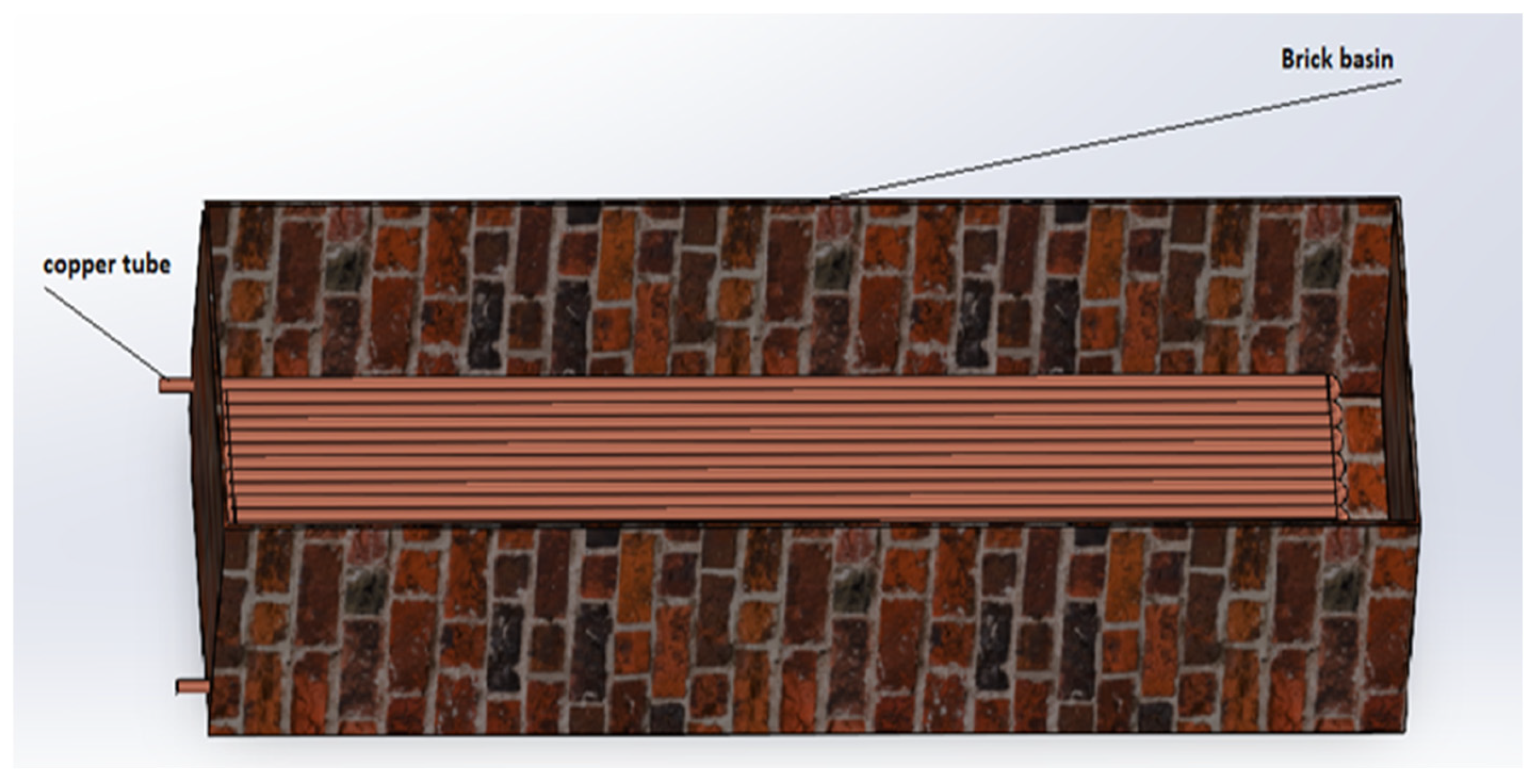
To ensure a large quantity of wool washing per day in an industrial factory, the project is primarily linked to a socio-economic solution. The system is designed with a pool based on the practical requirements of the factory, with dimensions of 5 m in length, 1.4 m in width, and 0.8 m in height, resulting in a total volume of 5.6 m3. The heat transfer fluid tube, made of copper to ensure efficient heat exchange, has a serpentine shape with a diameter of 40 mm and a thickness of 2 mm. Figure 2 illustrates the design of the pool and the heat transfer fluid tubes.

2.3. Thermodynamic Properties of Used Oils

To find the perfect heat transfer fluid to reaches our goal, a set of fluids were chosen and tested in the solar heating system proposed. These fluids recommended in the literature that have the characteristics mentioned in Table 1, are as follows:
(a)
Thermia B is designed to resist thermal decomposition when used within its recommended temperature range. Beyond this range, degradation, carbonization, or deposit formation may occur. The thermodynamic properties of Thermia B are provided in [18].
Thermia B is a mineral oil specially formulated for use as a heat transfer fluid in medium-temperature thermal systems. It is characterized by good thermal stability, low vapor pressure, and excellent oxidation resistance.
(b)
Heat Transfer Oil 32 has extended thermal stability for bulk oil temperatures of up to 300 °C in closed heat transfer systems. However, when exposed to air in open systems, its operating temperature should not exceed 180 °C. The thermodynamic properties of Heat Transfer Oil 32 are provided in [18].
(c)
Therminol vp1 is a popular heat transfer fluid used in various industrial applications, particularly in high-temperature heat transfer systems. The thermodynamic properties of Therminol vp1 are provided in [19].
(d)
Biphasic oil (Syltherm 800 manufactured by Dow Chemical Company, Midland, MI, USA) is a highly stable and durable silicone-based fluid designed for high-temperature operation in the liquid phase. It has a low fouling potential and can often remain in service for 10 years or more. The thermodynamic properties of Syltherm 800 are provided in [20].

3. Meshing and Mathematical Modeling

Firstly, to perform the simulation, the parameter range for this study includes conditions imposed at the inlet, outlet, solid domain, and fluid domain, along with the interface between the fluid and solid regions (Figure 3). At the entrance of the computational domain of the fluid (oils), a mass flow rate of 0.1 kg/s, a solar flux of 0.8 kW/m2 imposed by the cylindrical parabolic collector opening on the receiver, a turbulence intensity of 5%, a turbulent viscosity ratio of 10%, and a water temperature equal to the ambient temperature of 25 °C are specified. The temperature of the heat transfer fluid at the solar field outlet varies between 123 °C and 146 °C. At the outlet, ANSYS-CFX calculates the static pressure and imposes a zero-pressure gradient. The solid domain comprises a tube with a diameter of 40 mm and a thickness of 2 mm. The internal surface temperature of the pool is set to ambient temperature, with the heating surface of the absorber tube delivering a solar flux of 0.8 kW/m2. The absorber tube is made of copper, while the pool is built with bricks and features an inner steel layer. In the fluid domain, the heat transfer fluids considered include Thermia B, Heat Transfer Oil 32, biphasic oil (Syltherm 800), and Therminol vp1, while water is used as the pool fluid. At the interface between the fluid and solid regions, heat is transferred by conduction. The heated fluid in the coil transmits thermal energy to the water in the pool. The efficiency of this heat exchange depends on the thermal conductivities of the materials and the flow conditions of the fluid. Additionally, convective heat transfer occurs within the fluids themselves, between the moving particles of oil and water. At standard ambient conditions (25 °C and 1 atm), the thermophysical properties of water were taken as follows: a density of 997 kg/m3, specific heat capacity of 4.186 J/kg·K, thermal conductivity of 0.6 W/m·K, dynamic viscosity of 0.89 × 10⁻³ Pa·s, and 2260 kJ/kg of latent heat of vaporization. The heat transfer fluid circulating through copper tubes will heat the water used for washing the wool.
By leveraging Computational Fluid Dynamics (CFD) tools, which are increasingly integral to the design and optimization of industrial applications due to their high accuracy and robustness, this study employed a second-order discretization method, commonly adopted in both commercial and open-source CFD software, as the dominant approach. Several mesh configurations, including mini elements and Taylor–Hood elements, were evaluated to balance computational efficiency and accuracy. In our case, the final adopted mesh configuration consists of 3,578,908 nodes (Figure 4), selected after comparing alternative configurations of 882,000 nodes, 1,172,000 nodes, and 2,488,604 nodes. The temperature results stabilized with this mesh configuration, even when the number of nodes was increased to 3,868,964 (Figure 4). This confirms that the chosen mesh offers a good balance between accuracy and computational cost.
The problem was solved using CFD based on a mathematical model that integrates the conservation of mass, momentum, and energy, expressed in time-averaged tensor notation, which is presented below:
  • Continuity equation [21]:
u i ¯ x i = 0
  • Momentum equation [22]:
ρ u j ¯ u i ¯ x i = p ¯ x i + x j μ u i ¯ x j ρ u i ´ u j ´ ¯ ¯ + ρ g i
  • Energy equation [22]:
ρ u j ¯ T ¯ x j = 1 c p x j k T ¯ x j ρ c p T ´ ¯ u j ´ ¯
The change in the flow’s direction after it exits the pipe generates turbulence in the oil flow, significantly impacting heat transfer. Therefore, turbulence modeling plays a crucial role. In this context, the k-ε turbulence model is used, with the standard wall function for near-wall analysis. The boundary layer problem is not resolved on the mesh. A detailed description of this model and its implementation in ANSYS CFX is provided by Launder and Spalding (1972) and ANSYS (2009) [22,23].
The turbulent kinetic energy (Kt) and the dissipation rate of turbulent kinetic energy (ε) are defined as follows:
  • Turbulent kinetic energy (Kt) [22,23]:
ρ u j ¯ k t ¯ x t = x j μ + μ t σ k t k t ¯ x j + P k t + G k t + ρ ε t
  • Turbulent kinetic energy dissipation (ε) [22,23]:
ρ u j ε t x j = x j μ + μ t σ ε t ε t ¯ x j + c 1 ε t ε t k P k t + c 3 ε t G k t c 2 ε t ρ ε t 2 k t
The mean Nusselt number is defined as follows [21]:
N u m = d λ q T w T f
The Reynolds number is given by the following [22,23]:
R e = ρ υ D μ
  • The volume V of a rectangular pool is given by the following:
V = L W H
L, W, and H are the pool’s length, width, and height, respectively.
  • The energy required to heat the water is as follows:
Q = m C p Δ T
ΔT presents the temperature increase, Cp is the specific heat capacity of water, and m is the mass of water, calculated as follows:
m = V ρ
ρ presents the density of water.
  • Power supplied by solar concentrators:
The available rate of heat depends on the total surface area of the concentrators:
S t o t a l = N S u n i t
N is the number of concentrators.
In which the unit area of the concentrator module is as follows:
S u n i t = L c o n s e n t r a t o r H c o n s e n t r a t o r
P s o l a r = S t o t a l I
I is the heat flux imposed.
P e f f = P s o l a r η
η is the efficiency of the system.
  • The rate of heat transferred to the oil:
This equals the effective power Peff; it is calculated as follows:
P = m C p Δ T o i l
m presents the mass flow rate of the oil, Cp is the specific heat capacity, and ΔToil is the temperature increase of the oil. The energy transferred to the water is calculated as follows:
Q t r a n s = P e f f t
t presents the time.

4. Boundary Conditions

The boundary conditions used in ANSYS CFX were defined to accurately represent the system’s thermal and fluid dynamic behavior. At the inlet, a mass flow rate of 0.1 kg/s was specified, with a solar flux of 0.8 kW/m2 applied to the receiver through the parabolic trough collector. The heat transfer fluid entered the system at an initial temperature of 25 °C (ambient temperature), with turbulence conditions defined by a turbulence intensity of 5% and a turbulent viscosity ratio of 10. At the outlet, ANSYS CFX computed the static pressure while applying a zero-pressure gradient. The fluid domain included various heat transfer fluids flowing through the coil, such as Thermia B, Heat Transfer Oil 32, biphasic oil (Syltherm 800), and Therminol vp1, while the basin contained water. The solid domain consisted of a copper absorber tube with a diameter of 40 mm and a thickness of 2 mm, subjected to a heated surface flux of 0.8 kW/m2. The basin was constructed from brick with an inner steel lining, maintaining an inner surface temperature equal to ambient conditions. Fluid–solid interaction occurred, which involved heat conduction through the tube wall from the hot fluid inside the coil to the water in the basin. The effectiveness of this thermal exchange was primarily influenced by the thermal conductivity of the materials and the turbulent flow characteristics of the heat transfer fluid.

5. Results and Discussion

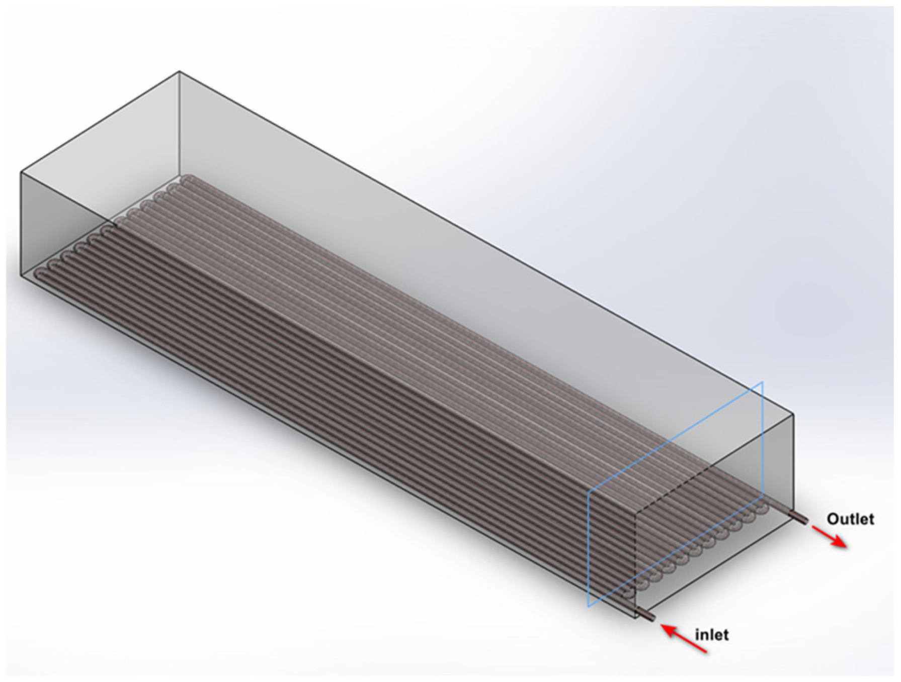
The CFD results obtained by the ANSYS CFX simulation generally show that the parabolic trough solar micro-plant outperforms natural gas systems. Also, the use of synthetic oils had an effective effect on the temperature values and distribution. The new design of washing pool in which a steel layer reinforces the pool provides the best thermal conductivity. Figure 5 presents the cross-sectional plane chosen for extracting the simulation results. This plane was carefully selected to provide a representative view of the thermal behavior within the system. It allows for capturing the temperature distribution across the entire flow domain of the heat transfer fluid and offers a detailed insight into the thermal variations near the oil inlet and outlet within the serpentine tubes. This positioning ensures that both the global and localized thermal performances can be accurately assessed.

5.1. The Effect of Water Pool Design on Temperature

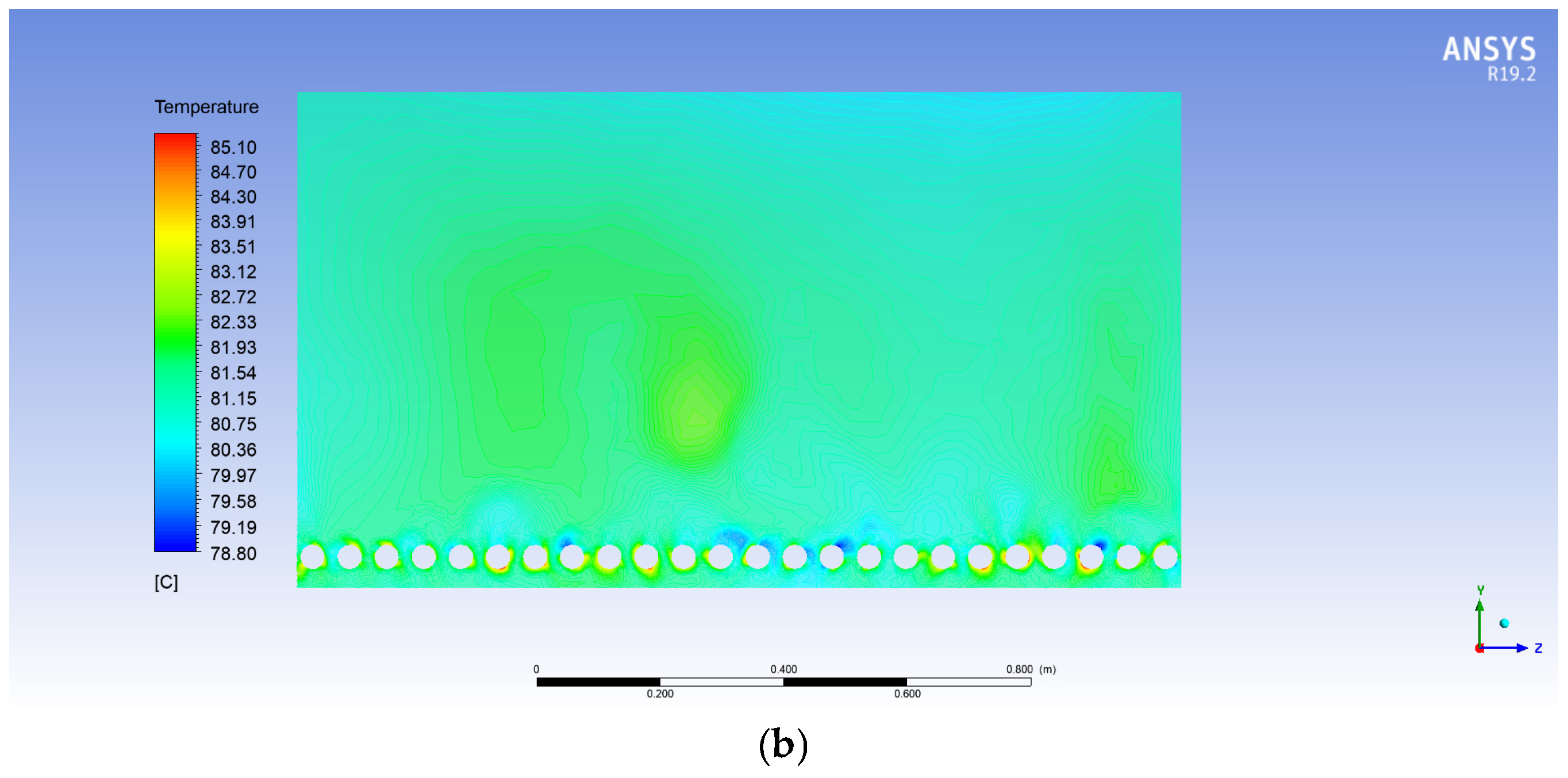
In Figure 6a, the water temperature in the pool with an internal steel layer appears slightly more uniform, with smaller variations; the water temperature varies from approximately 78.57 °C to 84.84 °C. Also, the brick pool without the steel layer shows a slightly different distribution; it varies from 78.80 °C to 85.10 °C, as shown in Figure 6b, with clearer distributions, especially in the central and lower regions. The heat is distributed more evenly in the steel-reinforced pool due to steel’s higher thermal conductivity than brick. This likely explains why temperatures are more consistent in the steel-lined pool. It seems to offer better thermal distribution, with more uniform temperatures and more efficient heat distribution. But the pool constructed from brick, with its lower thermal conductivity, exhibits greater temperature gradients, which means the heat diffuses less efficiently, creating areas with either higher or lower temperatures. This may indicate that while brick insulates better, it does not distribute heat as effectively as steel. This could lead to more pronounced temperature differences in the water over time. In summary, the use of steel appears to outperform that of brick in terms of thermal conductivity and uniform heat distribution, while brick, despite being more insulating, may cause localized heat accumulation.

5.2. The Temperature of Different Oils Inside the Copper Tubes

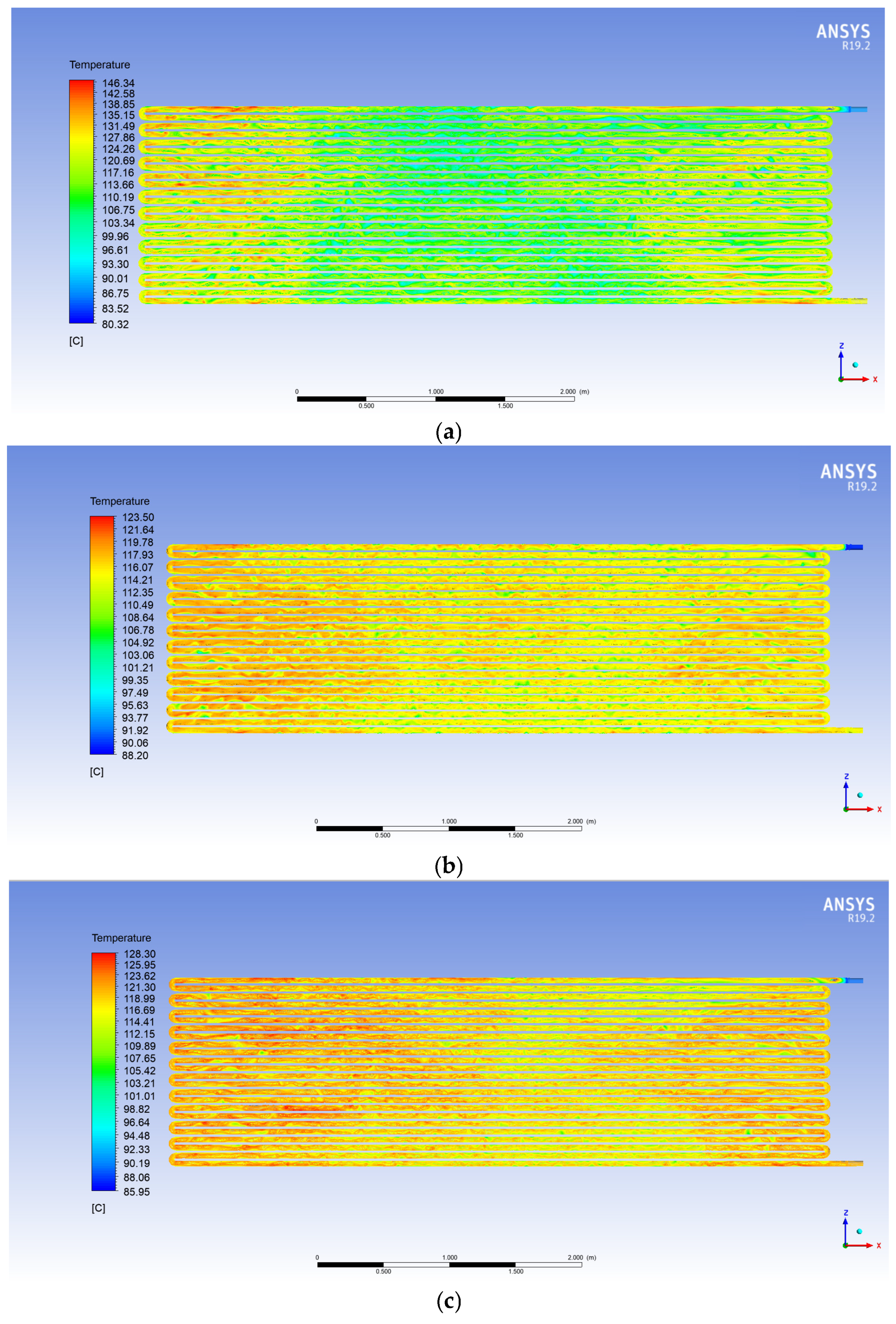
The numerical simulation results shown in Figure 7 present the heat transfer variation inside the copper tubes. They demonstrate significant differences between the oils used. These variations are primarily due to the physical and thermodynamic properties of each oil, such as viscosity, heat capacity, and thermal conductivity. These parameters strongly influence the velocity of oil particles and their ability to transfer heat effectively to the surrounding medium.
(a)
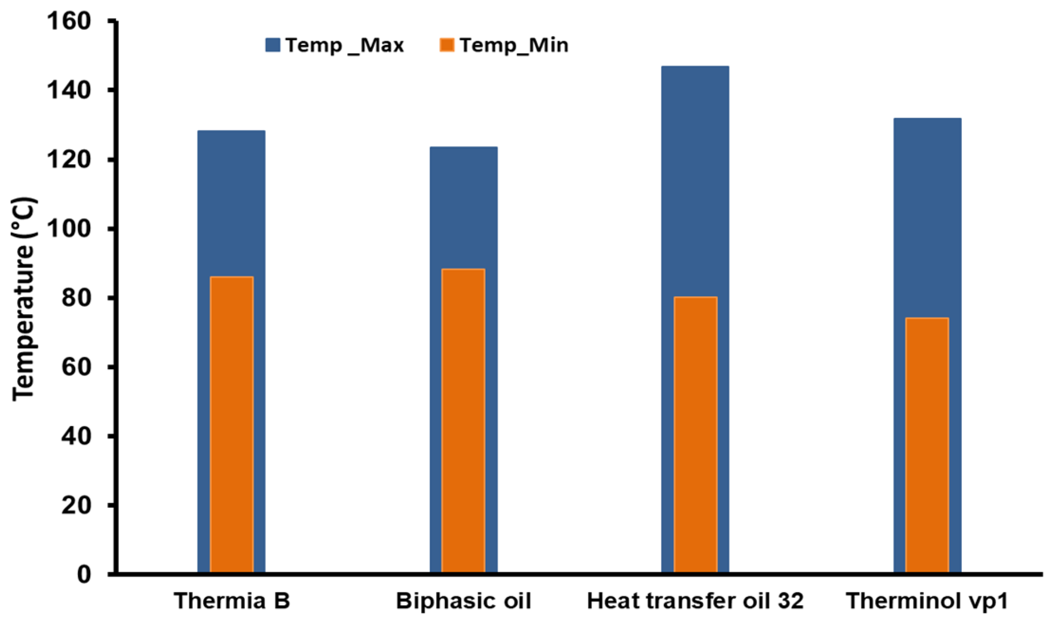
Heat Transfer Oil 32: This oil reaches a maximum temperature of 146.9+ °C in specific regions of the tubes. However, most areas in the tubes exhibit temperatures around 123 °C, as evidenced by the prevalence of green zones in Figure 7a. This uneven heat distribution can be attributed to the oil’s relatively high viscosity, which slows particle velocity and limits uniform heat diffusion within the tube. Despite achieving a higher maximum temperature than the other oils, the overall heat transfer efficiency of Heat Transfer Oil 32 appears reduced, as only a small portion of the tube reaches this elevated temperature. This may indicate inefficiency in transferring heat to the water in the water pool compared to oils with a more uniform temperature distribution (Figure 7a).
(b)
Biphasic oil: This oil achieves a maximum temperature of 123.5 °C, close to the average temperature observed in different regions of the tubes. This indicates moderate heat transfer with average efficiency for heating the water pool. The heat distribution is more uniform than in Heat Transfer Oil 32 but less consistent than in Thermia B. Biphasic oil may offer a compromise between thermal efficiency and temperature stability, but its performance remains inferior to oils like Thermia B in terms of achieving a homogeneous thermal distribution (Figure 7b).
(c)
Thermia B: This oil has a maximum temperature of 128.3 °C, slightly lower than Heat Transfer Oil 32. However, the distribution of temperature within the tubes is much more uniform, with the extensive red zones indicating high temperatures over a larger portion of the tubes. This homogeneity suggests a better capacity for consistently transferring heat to the water pool, maximizing thermal efficiency. Thermia B’s ability to maintain a uniform distribution of high temperatures makes it more suitable for applications requiring consistent efficiency in heating large volumes of water or fluids (Figure 7c).
(d)
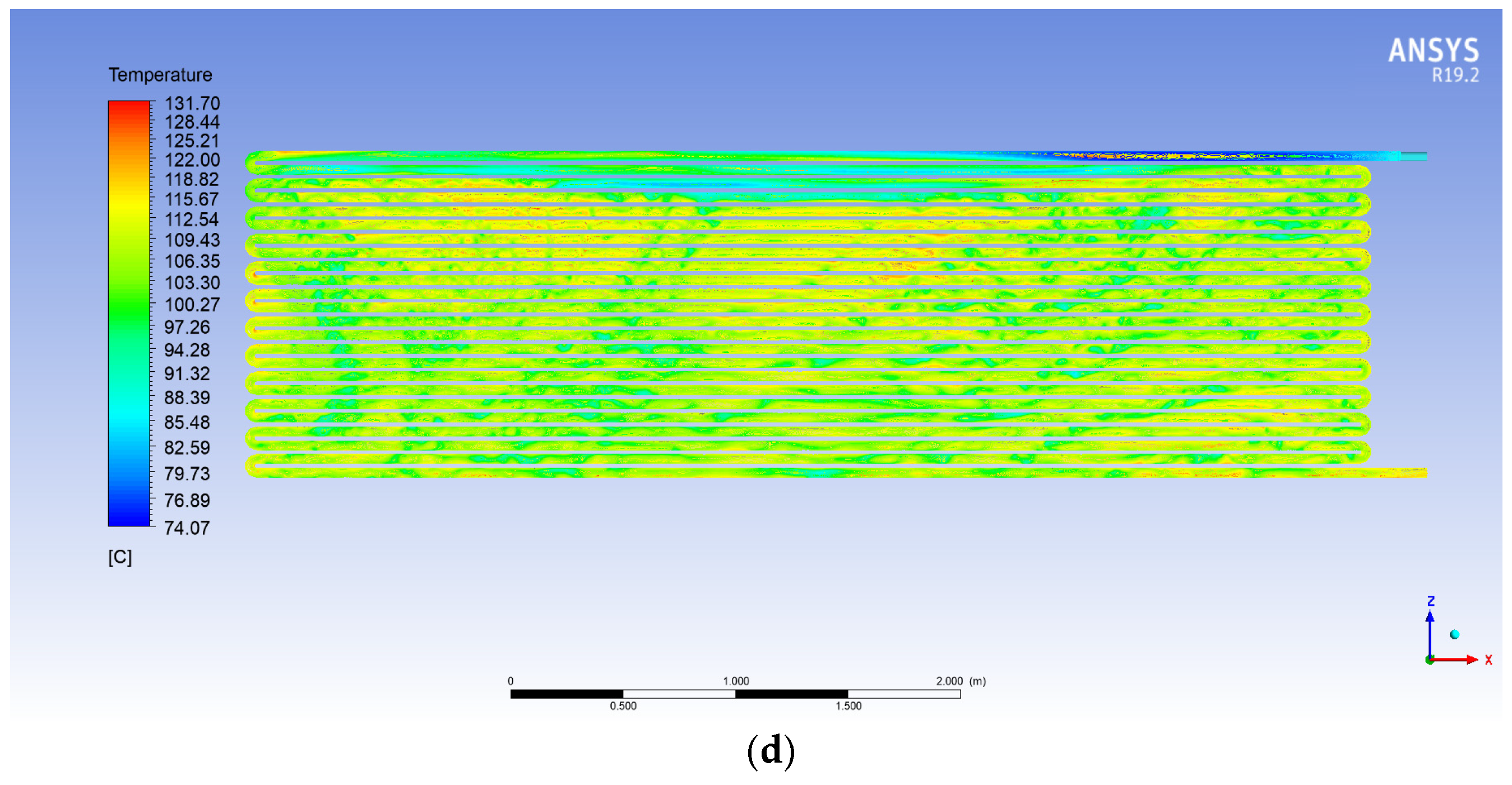
Therminol vp1: This oil reaches a maximum temperature of 131.7 °C, observed only at isolated points in the tubes. The majority of the tubes remain in a lower temperature range, between 92 °C and 100 °C. This suggests a limited ability of the oil to maintain high temperatures over a significant portion of the tubes, reducing its effectiveness in heating the water pool. The lack of widespread high temperatures may be due to high viscosity or lower specific heat capacity, limiting the amount of heat the oil can transport and distribute. This makes it less effective for applications requiring uniform and efficient heat transfer (Figure 7d).
An uneven temperature distribution in the tubes, as seen with Heat Transfer Oil 32 and Therminol vp1, limits the overall thermal transfer efficiency. When certain areas of the tube remain at relatively low temperatures, heat transfer to the water is reduced, directly affecting the overall heating system performance. In contrast, an oil like Thermia B, with a broad distribution of high temperatures, ensures more consistent and efficient heat transfer.
Figure 8 shows the evolution of oil temperature in the width direction. The results indicate that Thermia B is the most efficient oil for ensuring homogeneous and effective heat transfer in copper tubes because it has smallest range of variation in temperature values [24], i.e., the uniformity distribution provided by this oil in terms of temperature and heat transfer ratio. This is what makes it preferable for industrial applications requiring uniform heating, such as solar heating systems or thermal processes demanding consistent efficiency. Conversely, Heat Transfer Oil 32 and Therminol vp1, while capable of achieving high maximum temperatures, suffer from uneven heat distribution (Figure 9), which limits their effectiveness. Biphasic oil offers a middle ground with average performance and may be suitable for less demanding applications in terms of thermal efficiency [25].

5.3. Influence of Synthetic Oil Type on Water Temperature

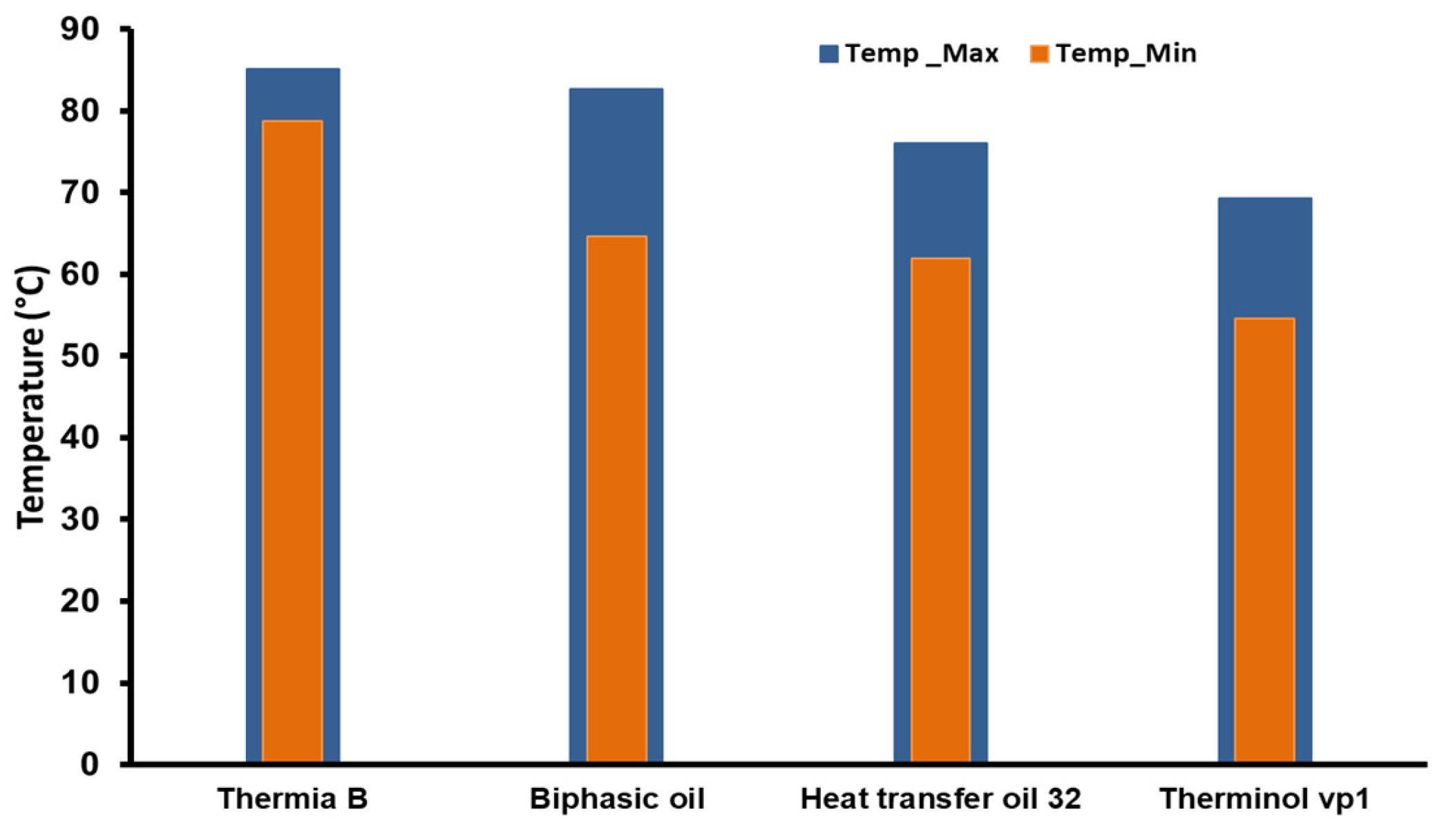
In the steel-reinforced pool, four synthetic oils were used: in Heat Transfer Oil 32, Biphasic oil, Thermia B, and Therminol vp1. We examined their effect on the water’s thermal distribution in the washing pool in which the oil tubes were immersed. The parameters measured included the oil temperature, water temperature, and heat transfer efficiency. We also considered some factors like the contact surface between the tubes and water, as well as fluid circulation. From Figure 9, the results of each oil show the following:
(a)
Heat Transfer Oil 32: This oil showed intermediate performance, with water temperatures varying between 61 °C and 76 °C. While partially meeting the requirements, its efficiency is limited by its lower heat transfer capacity, likely due to its higher viscosity, which impedes circulation and, consequently, heat transfer (Figure 10a).
(b)
Biphasic oil: This oil also demonstrated good results. Within the desired range, the water temperatures were between 64 °C and 82 °C. The oil’s biphasic design helps maintain a stable temperature, avoiding thermal fluctuations that could impair the wool-washing process. This stabilizing characteristic is especially critical for applications requiring constant temperatures (Figure 10b).
(c)
Thermia B: This oil stood out for its superior performance, achieving water temperatures up to 85 °C, with the lowest observed value equaling 78 °C. This performance can be attributed to its chemical formulation, which optimizes thermal conduction, enabling efficient heat transfer from the tubes to the water pool (Figure 10c).
(d)
Therminol vp1: This oil exhibited the weakest performance, with temperatures ranging between 54 °C and 69 °C. The limitations of this oil can be attributed to its low thermal conductivity and unsuitable viscosity, reducing its effectiveness as a heat transfer fluid in this study’s context (Figure 10d).
The results of the distribution of temperature in the pool’s height direction demonstrate the critical importance of selecting the appropriate heat transfer fluid for wool-washing processes (Figure 11); they demonstrate, again, that the Thermia B oil provides uniform and stable variation in water temperature in all points of the pool that depends on the oil’s ability to reach high temperatures and maintain its stable thermal performance, which qualifies it as the optimal choice. While the other oils performed satisfactorily, they fell short of Thermia B’s energy efficiency, underscoring the direct impact of heat transfer fluid selection on overall system thermal performance. Through water temperature evolution curves, Figure 11 and Figure 12 more clearly show the influence of changing the chosen synthetic oil. A significant temperature difference is observed between the various tested heat transfer fluids. Thermia B stands out for its ability to maintain the highest water temperatures, between 75 °C and 85 °C, indicating superior thermal performance, likely due to better conductivity and lower heat loss. Biphasic oil and Heat Transfer Oil 32 follow intermediate trajectories, with water temperatures ranging from 67 °C to 77 °C and 64 °C to 74 °C, respectively, suggesting moderate thermal performance suitable for industrial heating applications. In contrast, Therminol vp1 shows the lowest water temperature range, starting from 55 °C to 66 °C, which indicates lower thermal efficiency, but it may still be useful for applications requiring regulation at moderate temperatures.

5.4. The Effect of Oil Velocity on Heat Exchange

The serpentine design of the tube, in which the heat transfer fluid circulates, forces the fluid to follow a longer and more complex path. This design aims to decrease pressure through the bends in the tube and changes in flow direction. These features reduce the oil’s velocity and flow rate compared to a straight tube. The lower velocity of the oil within the tube allows for an extended residence time, facilitating better heat transfer to the water. Consequently, the prolonged contact time between the heat transfer fluid in the tube and water enhances the overall heat exchange efficiency.
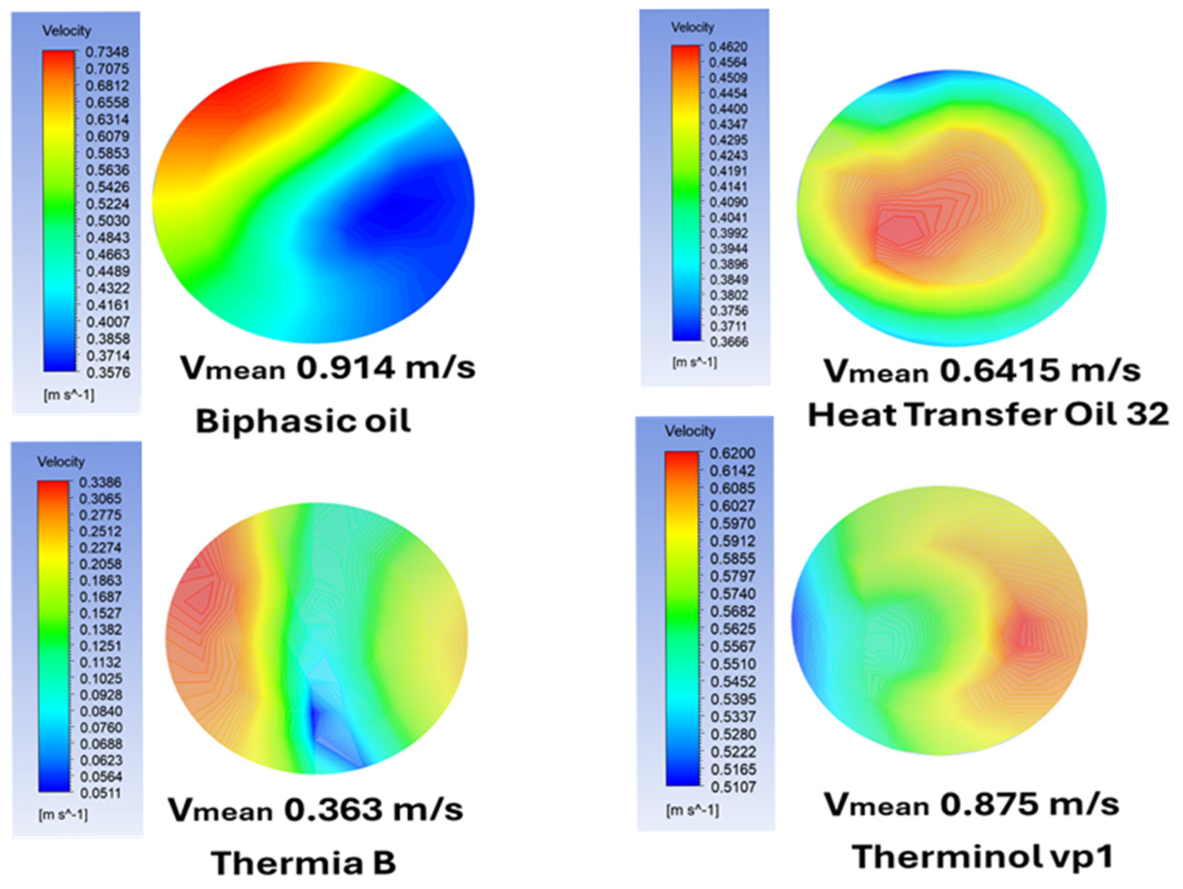
In our case, the numerical results of velocity at the tube outlet, as shown in Figure 13, reveal variations based on the type of oil used. Among the tested oils, Thermia B exhibited the lowest outlet velocity, with a mean value of 0.363 m/s, followed by Heat Transfer Oil 32 (0.6415 m/s), Therminol vp1 oil (0.875 m/s), and biphasic oil (0.914 m/s). This difference in velocity is primarily attributed to the viscosity of the oils. Thermia B demonstrated superior performance due to its lower velocity at the outlet, indicating that its viscosity was less affected by heat transfer processes. This characteristic allows its particles to spend more time transferring heat to the water. In contrast, the higher velocities observed for the other oils indicate a lower heat transfer efficiency compared to Thermia B.

6. Conclusions

This study explored the integration of a parabolic trough solar system to modernize water heating in the wool-washing industry, an operation known for its high energy consumption. The objective was to shift from conventional, fossil fuel-based methods to a renewable energy solution that improves thermal efficiency while promoting environmental sustainability.
A comprehensive optimization strategy was adopted, focusing particularly on the design of the water heating pool and the selection of suitable heat transfer fluids. The system was developed with a steel-reinforced pool interior to enhance thermal conductivity and ensure efficient heat distribution. Four synthetic oils—Thermia B, Heat Transfer Oil 32, Syltherm 800 (biphasic oil), and Therminol vp1—were rigorously evaluated.
Using advanced CFD simulations performed with ANSYS CFX and the k-ε turbulence model, the study analyzed the temperature profiles, heat transfer dynamics, and overall system performance. Among the fluids tested, Thermia B emerged as the most effective, demonstrating the ability to maintain uniform and elevated temperatures throughout the system.
Furthermore, the steel-reinforced pool showed significantly better thermal performance than a brick-only configuration, achieving optimal water temperatures between 78 °C and 85 °C—ideal for industrial wool washing.
These results highlight the strong potential of renewable energy systems in industrial applications. The proposed solar-powered solution offers both operational efficiency and environmental benefits, reinforcing its feasibility and setting a solid foundation for broader implementation in other energy-intensive sectors. This work represents a meaningful step toward more sustainable industrial practices. The numerical results confirm that the serpentine configuration enhances heat exchange by increasing the residence time of the heat transfer fluid. Among the tested oils, Thermia B exhibited the lowest outlet velocity, indicating stable viscosity and superior thermal performance. This outcome highlights the direct impact of the fluid’s thermodynamic properties on heat transfer. Future researchers are encouraged to investigate the influence of transient regimes, study fluid–thermal structure interactions, and explore alternative geometric configurations to further optimize the performance of parabolic trough solar systems.

Author Contributions

Conceptualization, H.M., D.M. and M.G.O.; methodology, H.M.; software, H.M., D.M. and L.M.; validation, G.L., A.B. and C.P.; formal analysis, H.M.; investigation, D.M.; resources, M.G.O.; data curation, D.M.; writing—original draft preparation, H.M.; writing—review and editing, M.G.O. and L.M.; visualization, D.M.; supervision, A.B. and L.M.; project administration H.M.; funding acquisition, G.L. and C.P. All authors have read and agreed to the published version of the manuscript.

Funding

This work was supported by a grant from the Ministry of Research, Innovation and Digitalization: project number PNRR-C9-I8-760111/23.05.2023, code CF48/14.11.2022.

Institutional Review Board Statement

Not applicable.

Informed Consent Statement

Not applicable.

Data Availability Statement

The original contributions presented in this study are included in the article. Further inquiries can be directed to the corresponding author.

Conflicts of Interest

The authors declare no conflicts of interest.

Nomenclature

u i ´ Instant fluctuation of velocity in the x direction (m/s)
G k t Generation of turbulent kinetic energy due to the buoyancy force
P k t Generation of turbulent kinetic energy
T ´ Fluctuation in temperature (K)
T ¯ The mean temperature (K)
c 3 Ɛ t and c 2 Ɛ t
c p
σ Ɛ t and σ k t Specific heat (J/kg.K)
Ɛ
D
ɛtDissipation of kinetic energy
rHeight (cm)
i and jDissipation of turbulent kinetic energy
ktDiameter
Lith and jth elements
TTurbulent kinetic energy
uLength (m)
g Temperature of fluid (K)
k Inlet velocity (m/s)
p Gravity (m/s2)
k Kinetic energy
p Pressure (Pa)
t Total
x System coordinate (i = x, y, z- j =x, y, z).
μ Viscosity (kg/m s)
hConvective transfer coefficient
QThe convective heat flux

References

  1. Vade, A.; Tari, S.; Athalye, A. Assessing Energy Emissions and Environmental Impact of Wool Processing: A Case Study of an Indian Textile Mill. Sustain. Polym. Energy 2024, 2, 10005. [Google Scholar] [CrossRef]
  2. Popescu, C.; Stanescu, M.D. Eco-Friendly Processing of Wool and Sustainable Valorization of This Natural Bioresource. Sustainability 2024, 16, 4661. [Google Scholar] [CrossRef]
  3. Russell, I.M. Sustainable wool production and processing. In Sustainable Textiles, Woodhead Publishing Series in Textiles; Blackburn, R.S., Ed.; Woodhead Publishing: Cambridge, UK, 2009; pp. 63–87. [Google Scholar] [CrossRef]
  4. Czaplicki, Z.; Matyjas, Z.E.; Strzelecki, S. Scouring of Sheep Wool Using an Acoustic Ultrasound Wave. FIBRES Text. East. Eur. 2021, 6, 44–48. [Google Scholar] [CrossRef]
  5. Iglesias, M.S.; Sequeiros, C.; García, S.; Olivera, N.L. Eco-friendly anti felting treatment of wool top based on biosurfactant and enzymes. J. Clean. Prod. 2019, 220, 846–852. [Google Scholar] [CrossRef]
  6. Matlhoko, K.S.; Vermaas, J.F.; Cronjé, N.; van der Merwe, S. Assessing the effectiveness of traditional wool scouring for small-scale farmers in South Africa: A study on detergents and scouring time. Res. J. Text. Appar. 2025, 29, 19–39. [Google Scholar] [CrossRef]
  7. Bhavsar, P.; Zoccola, M.; Dalla Fontana, G.; Pallavicini, M.; Roda, G.; Bolchi, C. Sustainable Routes for Wool Grease Removal Using Green Solvent Cyclopentyl Methyl Ether in Solvent Extraction and Biosurfactant Wool Protein Hydrolyzate in Scouring. Processes 2023, 11, 1309. [Google Scholar] [CrossRef]
  8. Kunik, A.; Semeshko, O.; Asaulyuk, T.; Saribyekova, Y.; Myasnykov, S. Development of a two-step technology of scouring wool by the method of high-energy discrete treatment. East. Eur. J. Enterp. Technol. 2016, 4, 36–43. [Google Scholar] [CrossRef]
  9. Dragović, N.; Urošević, S.; Vukovic, M. Impact of renewable energy resources on textile industry. In Proceedings of the IV International Conference “Modern Trends and Innovations in the Textile Industry”, Belgrade, Serbia, 16–17 September 2021. [Google Scholar]
  10. Mokhtar, G.; Boussad, B.; Noureddine, S. A linear Fresnel reflector as a solar system for heating water: Theoretical and experimental study. Case Stud. Therm. Eng. 2016, 8, 176–186. [Google Scholar] [CrossRef]
  11. Famiglietti, A.; Lecuona-Neumann, A. Feasibility analysis of an industrial turbocharged solar air heater using linear Fresnel collectors. AIP Conf. Proc. 2023, 2815, 140005. [Google Scholar] [CrossRef]
  12. Nunayon, S.S.; Akanmu, W.P. Potential application of a thermosyphon solar water heating system for hot water production in beauty salons: A thermo-economic analysis. Case Stud. Therm. Eng. 2022, 32, 101881. [Google Scholar] [CrossRef]
  13. Li, D.; Wang, Z.; Wu, Y.; Yu, N.; Zhao, X.; Meng, L.; Arıcı, M. Combined solar and ground source heat pump heating system with a latent heat storage tank as a sustainable system to replace an oilfield hot water station. Energy 2024, 307, 132726. [Google Scholar] [CrossRef]
  14. Zhang, T.; Wang, F.; Gao, Y.; Liu, Y.; Guo, Q.; Zhao, Q. Optimization of a solar-air source heat pump system in the high-cold and high-altitude area of China. Energy 2023, 268, 126653. [Google Scholar] [CrossRef]
  15. Sekine, M.; Tsukamoto, N.; Masuhara, Y.; Furuya, M. Experimental study on thermal stratification in water pool with vertical heat source. Ann. Nucl. Energy 2024, 207, 110681. [Google Scholar] [CrossRef]
  16. Singh, S.; Chakraborty, P.R.; Kothadia, H.B. Experimental analysis of heat transfer characteristics of static water pool under low pressure vaporization. Int. J. Therm. Sci. 2023, 192, 108413. [Google Scholar] [CrossRef]
  17. Kazmi, S.M.S.; Munir, M.J.; Patnaikuni, I.; Wu, Y.F.; Fawad, U. Thermal performance enhancement of eco-friendly bricks incorporating agro-wastes. Energy Build. 2018, 158, 1117–1129. [Google Scholar] [CrossRef]
  18. Shell. Technical Data Sheet: Shell Heat Transfer S2, Shell Thermia B. 2014. Available online: https://www.shell.com (accessed on 1 May 2024).
  19. Sasol. Heat Transfer Oil 32: Heat Transfer Oil, Grade 32. Available online: https://products.sasol.com/pic/products/home/grades/ZA/5heat-transfer-oil-32/index.html (accessed on 10 April 2025).
  20. Eastman. THERMINOL VP-1 Heat Transfer Fluid. Available online: https://www.eastman.com/en/products/product-detail/71093459/therminol-vp-1-heat-transfer-fluid (accessed on 10 April 2025).
  21. Dow. Product Information: SYLTHERM 800. 2001. Available online: https://www.npl.washington.edu/TRIMS/sites/sand.npl.washington.edu.TRIMS/files/manuals-documentation/syltherm-800-technical-data-sheet.pdf (accessed on 10 April 2025).
  22. Hazmoune, M.; Aour, B.; Chesneau, X.; Debbache, M.; Ciupageanu, D.A.; Lazaroiu, G.; Hadjiat, M.M.; Hamidat, A. Numerical Analysis of a Solar Tower Receiver Novel Design. Sustainability 2020, 12, 6957. [Google Scholar] [CrossRef]
  23. Ince, N.Z.; Launder, B.E. On the computation of buoyancy-driven turbulent flows in rectangular enclosures. Int. J. Heat. Fluid. Flow. 1989, 10, 110–116. [Google Scholar] [CrossRef]
  24. ANSYS, Inc. Ansys Fluent 12.0 Theory Guide; ANSYS, Inc.: Canonsburg, PA, USA, 2009. [Google Scholar]
  25. Mgaidi, A.M.; Mohd Rafie, A.S.; Ahmad, K.A.; Zahari, R.; Abdul Hamid, M.F.; Marzuki, O.F. Numerical and experimental analyses of the flow around a rotating circular cylinder at subcritical regime of Reynolds number using k-ε and k-ω-SST turbulent models. ARPN J. Eng. Appl. Sci. 2018, 13, 954–961. [Google Scholar]
Figure 1. Scheme of solar wool-washing system.
Technologies 13 00308 g001
Figure 2. The water pool used for wool washing.
Technologies 13 00308 g002
Figure 3. Typical computational mesh for numerical analysis.
Technologies 13 00308 g003
Figure 4. Meshing test (Thermia B).
Technologies 13 00308 g004
Figure 5. Presentation of the selected plane for data extraction.
Technologies 13 00308 g005
Figure 6. (a) The evolution of water temperature in the brick pool. (b) The evolution of water temperature in the brick pool without a steel layer.
Technologies 13 00308 g006aTechnologies 13 00308 g006b
Figure 7. (a) Temperature distribution of Heat Transfer Oil 32 inside copper tubes. (b) Temperature distribution of biphasic oil inside copper tubes. (c) Temperature distribution of Thermia B inside copper tubes. (d) Temperature distribution of Therminol vp1 inside copper tubes.
Technologies 13 00308 g007aTechnologies 13 00308 g007b
Figure 8. Transversal variation in the oil temperature inside the tube.
Technologies 13 00308 g008
Figure 9. Maximum and minimum temperatures of tested oils.
Technologies 13 00308 g009
Figure 10. (a) Distribution of water temperature when using Heat Transfer Oil 32. (b) Distribution of water temperature when using biphasic oil. (c) Distribution of water temperature when using Thermia B. (d) Distribution of water temperature when using Therminol vp1.
Technologies 13 00308 g010aTechnologies 13 00308 g010b
Figure 11. Water temperatures under each synthetic oil.
Technologies 13 00308 g011
Figure 12. The maximum and minimum water temperatures.
Technologies 13 00308 g012
Figure 13. The different outlet oils’ velocities.
Technologies 13 00308 g013
Table 1. Thermodynamic properties of used oils at 100 °C [18,19,20].
OilsThermia BHeat Transfer Oil 32Biphasic OilTherminol vp1
Density (kg/m3)805817881.68999
Specific heat capacity (kJ/kg·k)2.4002.31.7111.775
Thermal conductivity (W/m·k)0.1290.110.12370.1277
Kinematic viscosity (mm2/s)5.153.860.986
Initial boiling point (°C)350210385257
Disclaimer/Publisher’s Note: The statements, opinions and data contained in all publications are solely those of the individual author(s) and contributor(s) and not of MDPI and/or the editor(s). MDPI and/or the editor(s) disclaim responsibility for any injury to people or property resulting from any ideas, methods, instructions or products referred to in the content.