Abstract
The increasing integration of wind turbines into the power grid has reduced the system frequency stability, necessitating the integration of energy storage systems in primary frequency regulation. This paper proposes an MPC-based control method to optimize the frequency response of a combined wind–storage system. An evaluation system is also developed to characterize frequency response stability and guide power dispatch. First, the system model and state-space equations for MPC are established. Then, the control strategy is proposed to achieve the combined objective of minimizing power variation and frequency deviation. Finally, frequency stability is assessed using the evaluation system. MATLAB/Simulink case studies confirm the effectiveness of the proposed method in enhancing frequency regulation performance. The results show that this control strategy not only accelerates the response speed of the system frequency but also reduces its fluctuations, thereby improving the frequency stability of the system.
1. Introduction
The accelerating global energy transition has led to a continuous increase in the penetration of renewable energy sources, particularly wind power, in modern power systems. However, wind turbines (WTs), which connect to the grid via power electronic interfaces, lack the inertial response capability inherent to traditional synchronous generators. Large-scale wind power integration has significantly weakened the frequency regulation capability of power systems [1,2,3]. On the one hand, the connection of wind farms reduces the inertia of the system, causing the frequency to change more rapidly. On the other hand, the power fluctuations of wind farms increase the risk of power imbalance in the system, further exacerbating frequency fluctuations. Incidents such as the 2022 Texas grid failure and the 2019 United Kingdom blackout have highlighted frequency stability as a critical challenge for power systems with high shares of renewable energy [4,5].
To address this issue, researchers have proposed coordinated operation strategies that combine energy storage systems (ESS) with WTs to enhance frequency response capabilities. Existing studies primarily follow two technical pathways: improving the intrinsic regulation ability of WTs and deploying storage-assisted frequency regulation mechanisms. In WT-based regulation, virtual inertia control is widely studied. This approach emulates the inertial response of synchronous machines through additional control loops. A large-disturbance nonlinear model based on the internal dynamics of WTs has been developed to optimize the tuning of virtual inertia controllers [6]. A dynamic virtual inertia control method based on a tracking differentiator was introduced to suppress noise amplification and improve the primary frequency modulation (FM) performance of offshore wind farms (WFs). This approach was further enhanced by incorporating linear self-immunity control to improve robustness against secondary FM disturbances [7]. An adaptive distributed model predictive control (MPC) strategy combined with dynamic virtual inertia was proposed to improve the frequency stability of grid-connected offshore WFs by dynamically adjusting control parameters based on operating conditions [8]. Additionally, a novel integrated wind power frequency regulator was developed to enhance dynamic frequency stability under high wind power penetration. This method predefines load shedding operations and adjusts the pitch angle in real time, enabling doubly fed WTs to provide both virtual inertia and continuous primary FM support [9].
In the area of storage-assisted frequency regulation, sag control has been widely adopted due to its structural simplicity. A sag control algorithm incorporating charge state feedback was proposed for distributed battery ESSs, and its effectiveness in high renewable penetration scenarios was demonstrated through theoretical analysis and numerical simulation [10]. Another system combined decoupled PQ control with adaptive capacity sag control to achieve autonomous frequency regulation and load sharing in both grid-connected and islanded modes [11]. A microgrid-oriented adaptive sag control strategy was introduced to stabilize voltage and frequency during load variations by dynamically adjusting the sag coefficient through delayed power tracking [12]. For microgrids utilizing doubly fed induction generator grid-side converters, a primary frequency regulation method combining finite control set MPC and sag control was proposed. This approach enables communication-free frequency regulation while maintaining maximum power point tracking by dynamically adjusting sag gain via a DC bus-connected battery storage system [13]. To address the limitations of conventional sag control, an improved strategy was introduced that adjusts energy storage output power in response to variations in AC bus voltage and frequency, thereby enhancing the energy storage function [14].
In recent years, MPC has attracted considerable attention owing to its rolling optimization capabilities and effective handling of constraints. An adaptive MPC-based wind–storage cooperative FM strategy was proposed to enhance FM performance while reducing equipment degradation by employing hierarchical optimization and a novel power dispersion index [15]. A distributed MPC-based load frequency control method for a four-region interconnected grid was developed to mitigate load disturbances through partitioned, independent MPC co-optimization, accounting for WT impacts and generation rate constraints [16]. An attack-resilient load frequency control strategy for grid-connected wind power systems was introduced, integrating detection mechanisms and event-triggering schemes to enhance computational efficiency while ensuring operational security and economic performance [17]. A pipeline-based distributed MPC method was proposed to achieve coordinated multi-regional load frequency control in grids with high wind penetration. This method integrates virtual inertia control and load shedding to effectively suppress frequency deviations induced by load and wind speed fluctuations [18]. Another MPC-based cooperative wind–storage FM strategy was developed to minimize grid frequency deviation by optimizing WT and energy storage power commands. Equipment protection was addressed through adaptive wind speed constraints and load state management [19]. A summary table of the literature review is listed in Table 1.

Table 1.
The literature review summary table.
Despite these advancements, three critical limitations persist in current research. First, conventional methods fail to reconcile the dynamic discrepancies between wind and storage systems and often overlook the coupling effects inherent in the frequency regulation process. Second, existing dynamic weighting algorithms are mostly based on single factors or static weighting distributions, making it difficult to adapt to dynamic scenarios such as large fluctuations in wind turbine power, complex response characteristics of energy storage systems, and frequent fluctuations in system frequency. Finally, existing performance metrics lack integrated assessments of dynamic response, power allocation, and system degradation. To address these challenges, a frequency response optimization strategy based on MPC is proposed for combined wind–storage systems. A comprehensive evaluation framework is also developed, incorporating both technical performance and system health indicators. The main contributions are as follows: (1) a state-space model is established, incorporating WT output, energy storage state-of-charge (SOC) constraints, and grid frequency characteristics; (2) a rolling optimization control framework based on MPC is designed, enabling coordinated optimization of frequency deviation and power fluctuation through a dynamic weight adjustment algorithm; (3) a comprehensive evaluation index system is proposed, integrating metrics for frequency response, power fluctuation, and lifetime degradation to enable a holistic assessment of system performance and health.
The subsequent chapters of this paper are organized as follows. Section 2 presents the mathematical modeling of the wind–storage hybrid system. Section 3 describes the MPC-based control framework. Section 4 introduces the comprehensive evaluation index system. Section 5 discusses the simulation results. Section 6 presents the conclusions.
2. Combined Wind and Storage System Model
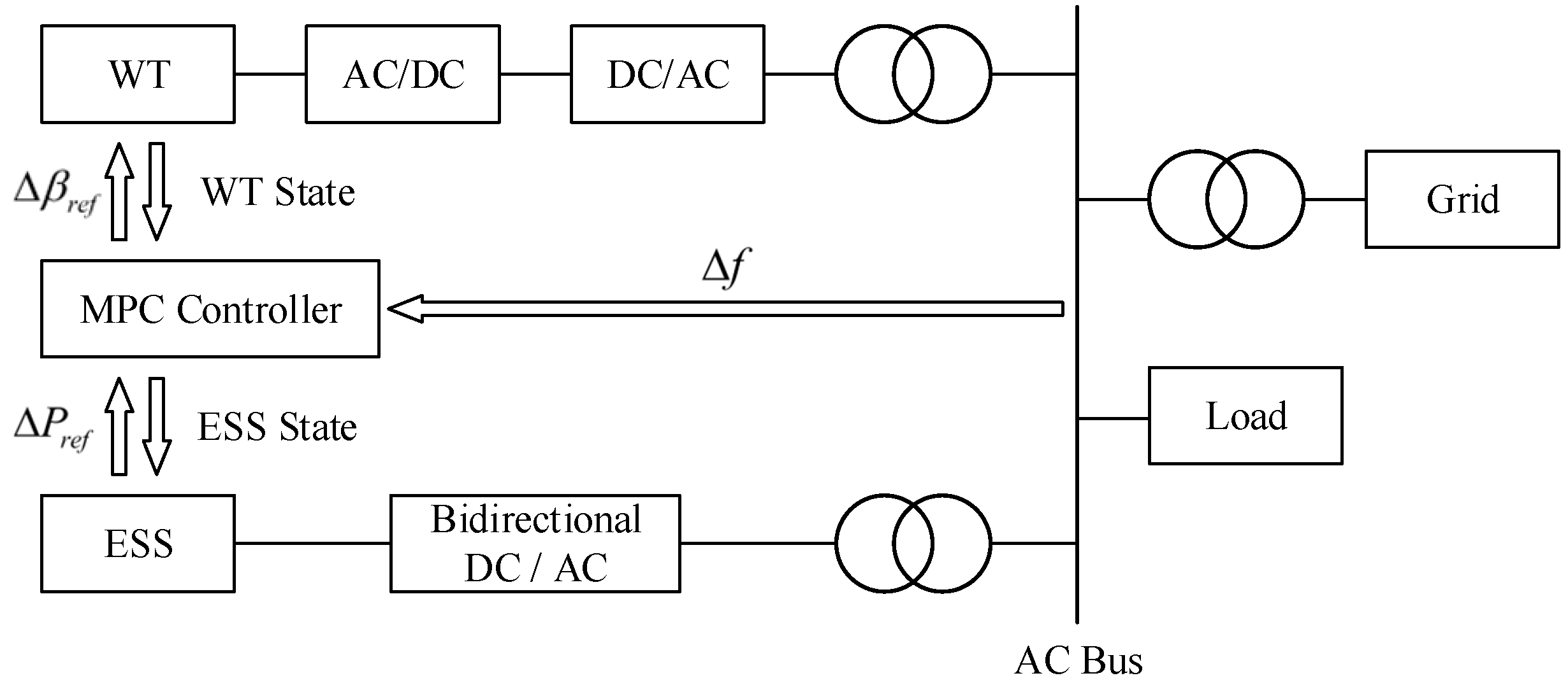
The combined wind–storage system model mathematically represents the coordinated operation of WTs and ESSs. This model integrates the stochastic output of WTs with the regulation capabilities of ESSs to enable optimized control strategies. The objective is to achieve power output smoothing, improve power quality, and enhance grid integration flexibility. The system configuration considered in this study is illustrated in Figure 1. It comprises an AC grid, WT, ESS, transformer, converter, and load. The WT is connected to the AC bus through AC/DC and DC/AC converters. The ESS is connected via a bidirectional DC/AC converter. Both the load and the AC grid are directly connected to the AC bus.
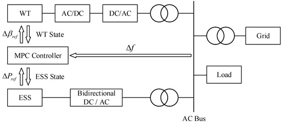
Figure 1.
The structure of the combined wind and storage system.
Fluctuations in load cause frequency deviations on the AC bus due to active power imbalances. The MPC adjusts the states of the WT and ESS based on real-time and forecasted grid frequency. It generates reference signals for WT pitch angle adjustment and ESS power output, thereby improving frequency regulation performance and enabling optimal allocation of wind and storage resources for frequency support.
2.1. Thermal Power Unit Model
In the combined wind–storage system, the thermal power unit is represented by a transfer function that describes the dynamic relationship between its input and output. This model typically characterizes a linear or nonlinear time-delay system, reflecting dynamic lag and power response caused by thermal inertia, fuel combustion rates, and turbine behavior. The transfer function enables analysis of the regulation capacity, response speed, and frequency and power balancing contribution of thermal power units within the hybrid system. Such analysis informs the design of optimal control strategies. Thermal power units, representative of conventional generation, primarily consist of a governor and turbine [20]. Their respective transfer functions are expressed as:
The turbine transfer function is:
where denotes the complex frequency, is the governor action time constant, denotes the high-pressure turbine mechanical torque, is the reheater time constant, and is the main inlet chamber time constant.
2.2. ESS Model
In a combined wind–storage system, the transfer function of the ESS serves as a mathematical tool for describing its dynamic behavior. This function quantitatively characterizes the relationship between the inputs and outputs of the system and captures its dynamic response to external control signals, including response speed, time delay, and energy conversion efficiency.
The transfer function of an ESS is typically formulated as a linear or nonlinear dynamic model. For battery-based systems, it may incorporate electrochemical properties such as charging and discharging time constants, internal resistance, and capacity limitations. These parameters govern the power output dynamics of the system, including the rate at which output power adjusts following a control command and the ability to reach the target power promptly. By contrast, for systems such as supercapacitors, the transfer function emphasizes rapid charge/discharge behavior and short-term energy storage characteristics. These systems are modeled to reflect their high-speed response and limited energy capacity.
The ESS transfer function enables performance analysis and optimization within the combined wind–storage system. For instance, during wind power fluctuations, it can predict the responsiveness of the ESS to stochastic changes, facilitating stabilized power output. Additionally, it provides a theoretical basis for designing ESS control strategies, ensuring compliance with system performance requirements while enhancing operational efficiency and extending equipment lifespan. The ESS exhibits fast response, controllability, and stable operation. Its dynamic behavior can be approximated by a first-order transfer function:
where is the energy storage response time constant.
2.3. WT Model
In a combined wind–storage system, the transfer function of the WT serves as a mathematical model representing the dynamic relationship between the input and output of the system. It captures the power response characteristics of the WT under varying wind speed conditions, as well as its internal dynamic processes, including blade rotational speed and generator torque regulation.
The WT transfer function typically involves a complex nonlinear system model due to the stochastic and multifactorial nature of wind power generation. Wind speed, the primary input, is inherently random and uncontrollable. While the wind speed–power relationship can be approximated using a wind power curve, the actual dynamic response must also consider aerodynamic blade behavior, mechanical inertia from the gearbox, and the electrical properties of the generator. For instance, a sudden change in wind speed necessitates a transitional period for the blade speed to reach a new equilibrium, which can be represented by a time constant in the transfer function.
The WT transfer function also facilitates analysis of its regulation capabilities within the combined system. For frequency regulation or power balance control, WTs can adjust output power by modifying the pitch angle or rotor speed. The transfer function quantitatively describes this dynamic behavior, providing a foundation for optimizing system-level control strategies. Accurate modeling of the WT transfer function enables improved coordination between wind power and energy storage, enhancing the overall stability and efficiency of the system. The pitch angle adjustment response is comparatively slow and can be modeled using a first-order transfer function:
where is the time constant of the pitch angle control response.
2.4. System Model
In the primary frequency regulation process of a combined wind–storage system, the system equations constitute a set of mathematical models that describe the dynamic behavior and interactions among the system components. These include the dynamic models of WTs, ESSs, thermal power units, and grid frequency. The dynamic equations for WTs characterize the influence of wind speed variations on WT output power and the response of WTs to grid frequency deviations. These models incorporate the wind speed–power curve, control strategies, and the mechanical and electrical dynamics of the turbines. The dynamic equations for the ESS describe its charging and discharging behavior in response to control commands and its capability to support frequency regulation. Key parameters include charging/discharging rates, capacity limits, and internal dynamic characteristics.
Thermal power unit dynamics are modeled based on their response to power commands and frequency changes. These equations account for the thermal inertia, fuel combustion rate, and turbine response characteristics of the unit. The grid frequency dynamics are expressed through a differential equation, linear or nonlinear, representing the relationship between the power imbalance (supply minus demand) and frequency variations. This model incorporates system inertia, damping effects, and the frequency response behavior of generators and loads.
By solving these equations jointly, the primary frequency regulation process of the entire wind–storage system can be simulated and analyzed. Optimizing the control strategy enables coordinated operation among system components, enabling rapid response to frequency deviations and ensuring stable power system operation. The system equations governing the primary frequency regulation of the combined wind–storage system are expressed as follows:
where denotes the position increment of the governor, is the primary frequency regulation gain of the thermal unit, represents the frequency deviation of the actual power grid, is the incremental thermal power output of the reheater, is the frequency regulation power variation of the thermal unit, is the frequency regulation power variation of the ESS, is the reference value of energy storage power variation predicted by the model, represents the pitch angle variation, is the model-predicted reference value of the WT pitch angle variation, is the WT frequency regulation power variation, is the slope of the WT power output curve, and represents the SOC of the ESS. is the sampling interval in the prediction model, denotes the capacity of the ESS, represents the load power variation, is the grid inertia time constant, and is the load regulation coefficient.
3. Optimization Strategy Based on Model Predictive Control
The MPC algorithm is an advanced control strategy that operates based on a system model and is widely applied in combined wind–storage systems. By constructing a mathematical representation of the system, MPC predicts its future dynamic behavior over a specified time horizon. It then optimizes the control inputs at each control cycle to achieve system performance objectives, including mitigation of wind power fluctuations, stabilization of grid frequency, and extension of ESS lifespan. MPC explicitly incorporates system constraints and solves an optimization problem to generate optimal control signals. This approach enables efficient and flexible control of the wind–storage system, ensuring dynamic adaptability and operational reliability.
3.1. Constraint Condition
In a combined wind–storage system, MPC constraints are formulated to ensure safe, stable, and efficient operation. These constraints limit the active power output and pitch angle variation of the WTs, the active power output and SOC of the ESS, and the frequency fluctuation of the grid. Restricting WT power output and pitch angle variation prevents operation beyond permissible limits during frequency regulation, protecting equipment and maintaining power generation efficiency. Constraints on the output power and SOC of the ESS prevent overcharging and overdischarging, extend system lifespan, and ensure energy availability for FM when required. Additionally, limiting grid frequency deviation helps maintain system stability and meet grid operation security standards. Appropriate constraint selection enables the MPC to optimize the control strategy while respecting the physical and operational limits of the system. This ensures coordinated operation of the wind–storage system and fulfillment of primary frequency regulation objectives. The constraint equations used in the model are as follows:
where is the active power output of the WT, is the maximum available active power of the WT, is the output power of the ESS, is the minimum allowable output power of the energy storage device, is the maximum allowable output power of the energy storage device, is the minimum allowable change in the pitch angle, is the maximum allowable change in the pitch angle, is the minimum SOC limit of the ESS, is the maximum SOC limit of the ESS, is the actual grid minimum value of frequency deviation, is the maximum value of frequency deviation of the actual grid, and is the variation in the grid power demand.
3.2. Dynamic Weight
In a combined wind–storage system, the objective function of the MPC algorithm employs dynamic weights to adaptively adjust the prioritization of control objectives in response to changes in system status and external conditions. For example, when grid frequency deviation is significant, the weight of the frequency regulation term is increased to prioritize grid stability; when the output power of the WTs exhibits large fluctuations, the weight related to WT operational health is increased to maintain stable WF operation; and when the ESS has low charge, the weight of the storage life protection term is elevated to preserve storage capacity. Dynamic weighting enhances the adaptability and flexibility of the control strategy. This approach allows for a balanced trade-off among system performance, economic efficiency, and equipment longevity, thereby improving the operational reliability of the combined wind–storage system under varying operating conditions. The degree of loss in the system components is calculated using the following expressions:
where is the loss degree of WT, is the loss degree of energy storage device, is the loss degree of grid frequency, is the historical record point, is the total number of historical record points, is the per unit value of the output power variation of WT at the historical record point, is the per unit value of the output power variation of energy storage device at the historical record point, and is the per unit value of the actual grid frequency variation at the historical record point. The corresponding optimization weights are then calculated based on the degree of losses in the WTs, storage devices, and grid frequency, as follows:
where is the optimal weight for WT output power fluctuation, is the optimal weight for energy storage output fluctuation, and is the optimal weight for grid frequency deviation.
3.3. Objective Function
The MPC objective function in the wind–storage combined system aims to minimize fluctuations in the active power output of the WTs, fluctuations in the active power output of the ESS, and deviations in grid frequency. Minimizing WT power fluctuations reduces the adverse effects of wind power intermittency and uncertainty on the grid while extending WT service life. Controlling fluctuations in energy storage output improves the charging and discharging strategy, maintains the health of storage equipment, and enhances cost-effectiveness. Reducing frequency deviation contributes to the stability of the power system and ensures compliance with grid frequency standards. By simultaneously considering these objectives, the MPC algorithm optimizes the overall performance of the combined system, promoting both effective wind power utilization and grid stability. The formal expression for the objective function is as follows:
where is the sampling time, is the total number of sampling steps, is the value of at the sampling time, is the value of at the sampling time, and is the value of at the sampling time.
4. Comprehensive Evaluation Index System
In a combined wind–storage system, establishing a comprehensive evaluation index system incorporating frequency response, power fluctuation, and lifetime degradation is essential. The frequency response index evaluates the ability of the system to regulate grid frequency deviations and its response speed, thereby ensuring power system stability. The power fluctuation index assesses the smoothness of the power output from WTs and the ESS, which is critical for mitigating the adverse effects of intermittent renewable energy on the grid. The lifetime degradation index focuses on the longevity of key components, particularly energy storage devices. By optimizing the control strategy, losses from charging and discharging can be reduced, extending equipment life and lowering operational costs. This evaluation framework quantitatively characterizes the operational performance and economic efficiency of the combined wind–storage system. It provides a scientific basis for system design optimization, control strategy development, and equipment selection, thereby supporting efficient, stable, and cost-effective operation. The structure of the comprehensive evaluation index system is illustrated in Figure 2.

Figure 2.
A comprehensive evaluation index system.
First, the degree of deterioration is calculated for each of the three components, namely, WT output power fluctuation, ESS output power fluctuation, and grid frequency fluctuation, using the following formula:
where is the actual value of the index, is the minimum value of the index, is the maximum value of the index.
Second, considering the various indicators in the system, a weighted sum of the individual deterioration degrees is used to determine the overall system degradation level:
where is the degree of degradation of the indicator, and is the overall degradation level of the system.
The system health is then classified into five levels: excellent, good, average, poor, and extremely poor. In the health level assessment of combined wind–storage systems, we use a ridge distribution membership function to calculate the membership of the system corresponding to different health levels. The ridge distribution membership function is a commonly used fuzzy function that effectively handles the fuzziness and uncertainty of system health status. The selection of thresholds is based on the critical points of system health status, which are derived by analyzing the distribution of performance indicators under different operating conditions. Based on the overall deterioration degree, the membership degree for each health level is computed using a ridge distribution membership function:
where is the degree of deterioration, and is the membership degree corresponding to each health level.
Finally, the system health level is determined using the maximum membership degree principle, assigning the category with the highest membership degree as the final health assessment of the combined wind–storage system.
5. Case Study
5.1. Test System
The feasibility and effectiveness of the proposed combined wind–storage system for grid primary frequency regulation optimization were evaluated using the test system shown in Figure 3. This system includes a thermal power plant, a WF, an energy storage device, and a randomly fluctuating AC load. The total simulation duration was set to 500 s. Relevant system parameters are listed in Table 2. All simulations were performed using MATLAB/Simulink. The system comprises a 300 MW thermal power plant, a WF consisting of 100 1.5 MW permanent magnet direct drive WTs, a 0.5 MW·h energy storage device, and random fluctuating AC loads.

Figure 3.
The test system configuration.

Table 2.
Simulation parameters.
5.2. Control Performance
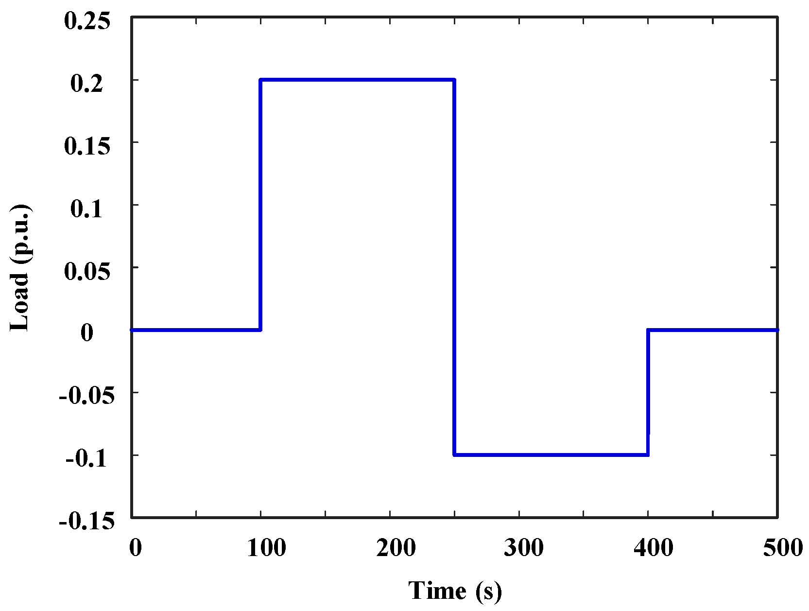
To verify the effectiveness of the proposed method, the load was increased by 0.2 p.u. at 100 s, decreased by 0.3 p.u. at 250 s, and finally increased by 0.1 p.u. at 400 s to simulate actual operating conditions. The load variation is depicted in Figure 4.
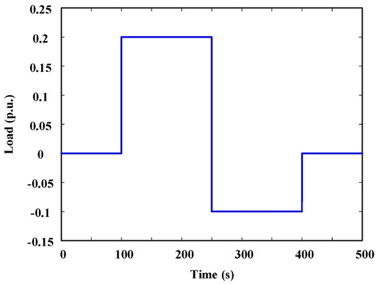
Figure 4.
Load changes.
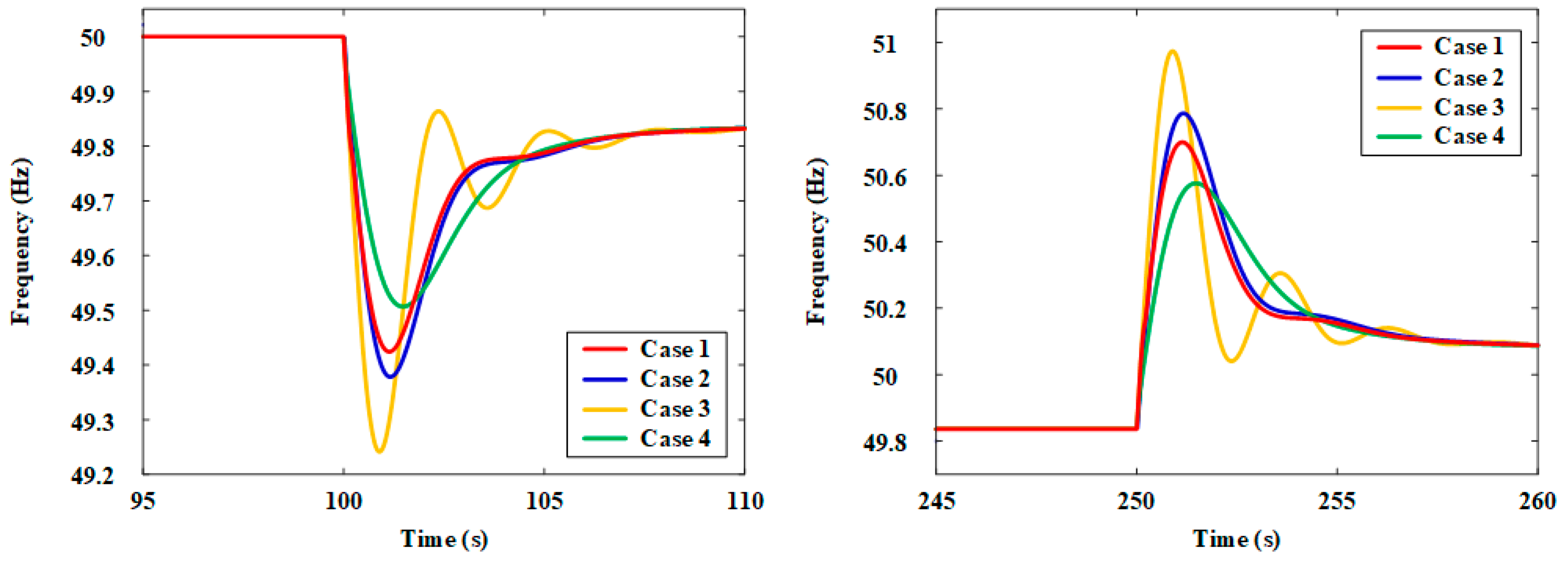
FM performance was compared under four scenarios, assuming a 25% wind power penetration rate: Case 1 involves the proposed method with both wind power and storage participating in FM; in Case 2, wind power participates, but storage does not; in Case 3, neither wind power nor storage participates; Case 4 involves the method described in reference [21] with both wind power and storage participating in FM. The comparison results appear in Figure 5.
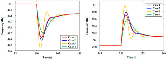
Figure 5.
The system frequency response.
Figure 5 shows that the proposed method achieves superior primary frequency regulation throughout the simulation compared to the other cases. When the system load experiences significant fluctuations, the MPC controller effectively reduces frequency deviation and accelerates the system’s frequency recovery time. Compared to Case 2, the proposed method significantly reduces system frequency fluctuations. Compared to Case 3, the proposed method accelerates the system’s frequency regulation speed. Compared to Case 4, although the proposed method slightly increases the amplitude of the frequency response, it accelerates the system’s frequency regulation speed, which is more advantageous for the system’s frequency regulation overall.
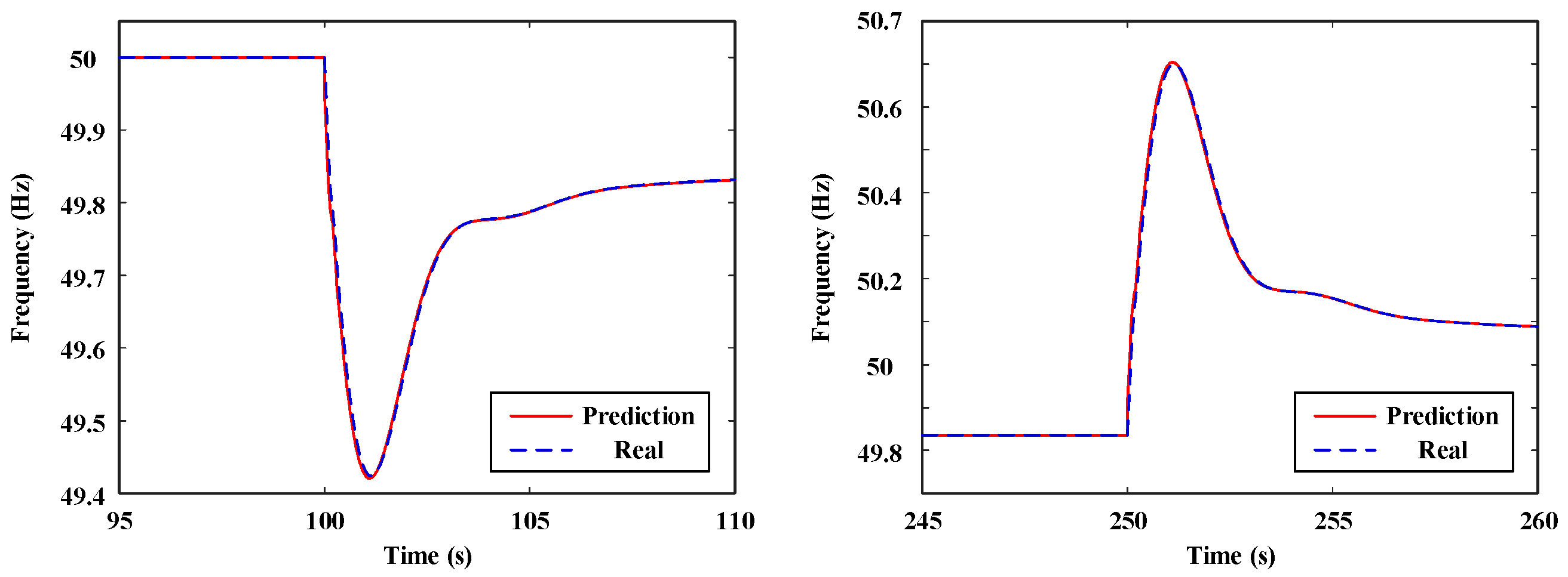
Figure 6 presents a comparison between the MPC-predicted system frequency fluctuation and the actual grid frequency fluctuation.
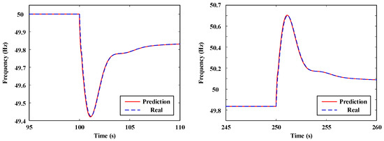
Figure 6.
Frequency prediction.
The results demonstrate that the MPC accurately predicts frequency fluctuations, maintaining effective control under dynamic system changes.
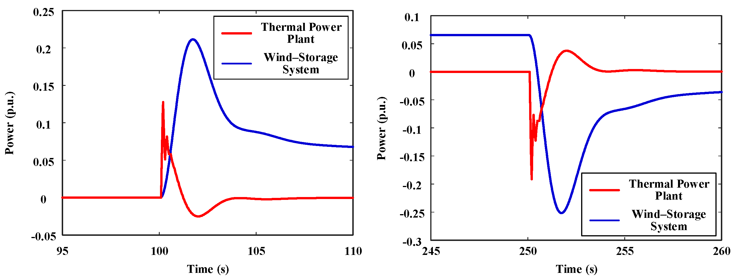
Figure 7 displays the output power of the conventional thermal power plant and the wind–storage system under the proposed control strategy.
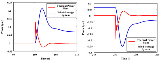
Figure 7.
Power output.
When the load increases abruptly, the wind–storage system promptly compensates for the power demand due to the slower response of the traditional thermal power plant. As the thermal plant output gradually rises and stabilizes, the wind–storage system output correspondingly decreases and stabilizes.
5.3. Evaluation Result
To further verify the effectiveness of the method proposed in this paper, using the comprehensive evaluation index system established in this paper, the experimental results of the method proposed in this paper are compared with those of the method proposed in reference [21]. Table 3 shows the comparison results of WT, ESS, grid, and system deterioration degrees. Table 4 shows the membership degrees of the system corresponding to different health levels under two different control methods and the final evaluation results.

Table 3.
Deterioration degrees.

Table 4.
Membership degrees.
It can be seen from Table 3 and Table 4 that after the evaluation of the comprehensive evaluation index system established in this paper, the proposed method effectively improves the operating state of the combined wind–storage system. The deterioration degrees of the WT, ESS, grid, and system are reduced, and the final system health level is evaluated as excellent.
6. Conclusions
A control method based on the MPC algorithm was developed to optimize the frequency response of a combined wind–storage system. This method addresses the frequency stability challenges caused by the large-scale integration of WTs into the power grid. By establishing the system model and formulating the state-space equations for MPC, optimal control was achieved by minimizing the sum of power variation and frequency deviation as the objective function. An evaluation system was designed to characterize frequency response stability and guide power allocation within the wind–storage system. MATLAB/Simulink case studies demonstrated that the proposed MPC-based optimization method effectively enhances frequency regulation performance. Through coordinated power allocation between WTs and energy storage devices, the system restored stability more rapidly in response to frequency disturbances, significantly reduced frequency deviation, and improved frequency response stability. The MPC-based FM control method and evaluation system presented provide a practical solution to frequency stability issues arising from large-scale wind power integration. The method significantly improves system FM performance and shows strong potential for application and further development. Future work may investigate its adaptability across different grid structures and operating conditions, and explore synergistic optimization with other advanced control strategies to enhance grid stability and reliability.
Author Contributions
Conceptualization, J.H. and H.Z.; methodology, Y.L.; software, J.W.; validation, X.C. and L.B.; formal analysis, J.H.; investigation, H.Z.; resources, Y.L.; data curation, J.W.; writing—original draft preparation, Y.L.; writing—review and editing, Y.L.; visualization, J.H.; supervision, J.W.; project administration, J.H.; funding acquisition, J.H. All authors have read and agreed to the published version of the manuscript.
Funding
This research was funded by the State Grid Shanxi Electric Power Company Technology Project [520530230003] and the National Key R&D Program of China under Grant [2022YFF0608700].
Data Availability Statement
The data presented in this study are available upon request from the corresponding author due to confidentiality reasons.
Conflicts of Interest
The authors declare no conflicts of interest.
Abbreviations
The following abbreviations are used in this manuscript:
| WT | Wind Turbine |
| ESS | Energy Storage System |
| FM | Frequency Modulation |
| WT | Wind Farm |
| MPC | Model Predictive Control |
| SOC | State-of-Charge |
References
- Chen, C.; Tang, W.; Xia, Y.; Chen, C. Hybrid-energy storage optimization based on successive variational mode decomposition and wind power frequency modulation power fluctuation. Energies 2024, 17, 4391. [Google Scholar] [CrossRef]
- Chen, L.; Zheng, P.; Gao, W.; Jiang, J.; Chang, J.; Wu, R.; Ai, C. Frequency modulation control of hydraulic wind turbines based on ocean used wind turbines and energy storage. Energies 2022, 15, 4086. [Google Scholar] [CrossRef]
- Qin, R.; Chen, J.; Li, Z.; Teng, W.; Liu, Y. Simulation of secondary frequency modulation process of wind power with the aid of flywheel energy storage. Sustainability 2023, 15, 11832. [Google Scholar] [CrossRef]
- Qing, M.; Tang, F.; Liu, D.; Liang, W.; Du, N.; Liu, F. Calculation of Limit Proportion of Wind Power Considering Primary Frequency Modulation and Frequency Constraints. In Proceedings of the 2020 IEEE Power & Energy Society General Meeting (PESGM), Montreal, QC, Canada, 2–6 August 2020. [Google Scholar]
- Wang, C.; Xu, J.; Wang, L.; Song, D. Research on optimization strategy of grid frequency modulation based on doubly-fed wind turbines. Int. J. Low Carbon Technol. 2021, 16, 229–239. [Google Scholar] [CrossRef]
- Ravanji, M.H.; Cañizares, C.A.; Parniani, M. Modeling and control of variable speed wind turbine generators for frequency regulation. IEEE Trans. Sustain. Energy 2019, 11, 916–927. [Google Scholar] [CrossRef]
- Qi, X.; Madonski, R.; Huang, C.; Ke, Y. Tracking-differentiator-based dynamic virtual inertial control of offshore wind power plant for frequency regulation. Int. J. Electr. Power Energy Syst. 2022, 141, 108150. [Google Scholar] [CrossRef]
- Qi, X.; Lei, L.; Yu, C.; Ma, Z.; Qu, T.; Du, M.; Gu, M. Adaptive distributed MPC based load frequency control with dynamic virtual inertia of offshore wind farms. IET Control Theory Appl. 2024, 18, 2228–2238. [Google Scholar] [CrossRef]
- Fu, Y.; Zhang, X.; Hei, Y.; Wang, H. Active participation of variable speed wind turbine in inertial and primary frequency regulations. Electr. Power Syst. Res. 2017, 147, 174–184. [Google Scholar] [CrossRef]
- Shim, J.W.; Verbič, G.; Kim, H.; Hur, K. On droop control of energy-constrained battery energy storage systems for grid frequency regulation. IEEE Access 2019, 7, 166353–166364. [Google Scholar] [CrossRef]
- Zhang, Y. Capacity-Based Adaptive Droop Control for Battery Energy Storage Operation. In Proceedings of the 2017 IEEE Power & Energy Society General Meeting, Chicago, IL, USA, 16–20 July 2017. [Google Scholar]
- Xu, H.; Pan, Z. An Adaptive Droop Control Strategy of Energy Storage Control for Microgrid with Wind Power and Energy Storage Systems. In Proceedings of the 2017 20th International Conference on Electrical Machines and Systems (ICEMS), Sydney, NSW, Australia, 11–14 August 2017. [Google Scholar]
- Gomez, L.A.; Lourenco, L.F.; Grilo, A.P.; Salles, M.; Meegahapola, L.; Sguarezi Filho, A.J. Primary frequency response of microgrid using doubly fed induction generator with finite control set model predictive control plus droop control and storage system. IEEE Access 2020, 8, 189298–189312. [Google Scholar] [CrossRef]
- Liu, H.; Labonne, J.; Coste, P.; Huchet, E.; Plagnes-Juan, E.; Rives, J.; Veron, V.; Seiliez, I.; Bolliet, V. Looking at the complex relationships between migration behavior and conditional strategy based on energy metabolism in the European glass eel (Anguilla anguilla). Sci. Total Environ. 2019, 696, 134039. [Google Scholar] [CrossRef]
- Zhu, Y.; Shi, Q.; Yao, S.; Wei, Z. Adaptive MPC and power dispersion index based improved hierarchical frequency regulation for wind-storage integrated system. J. Energy Storage 2025, 107, 115006. [Google Scholar] [CrossRef]
- Yan, Y.; Zhang, Y.; Liu, X. Distributed MPC Strategy with Application to AGC in the Presence of Variable Speed Wind Turbine. In Proceedings of the 2015 34th Chinese Control Conference (CCC), Hangzhou, China, 28–30 July 2015. [Google Scholar]
- Hu, Z.; Su, R.; Ling, K.V.; Guo, Y.; Ma, R. Resilient event-triggered MPC for load frequency regulation with wind turbines under false data injection attacks. IEEE Trans. Autom. Sci. Eng. 2023, 21, 7073–7083. [Google Scholar] [CrossRef]
- Liu, X.; Wang, C.; Kong, X.; Zhang, Y.; Wang, W.; Lee, K.Y. Tube-based distributed MPC for load frequency control of power system with high wind power penetration. IEEE Trans. Power Syst. 2023, 39, 3118–3129. [Google Scholar] [CrossRef]
- Sun, S.; Yu, P.; Cheng, Y.; Wang, S.; Wang, Y.; Zhang, Z.; Kou, P. Model Prediction Control Scheme of Wind Farm with Energy Storage for Frequency Support. In Proceedings of the 2021 11th International Conference on Power and Energy Systems (ICPES), Shanghai, China, 18–20 December 2021. [Google Scholar]
- Liu, Q.; He, S.; Lu, W.; Wang, H. Model predictive control method for battery energy storage assisting secondary frequency regulation. Electr. Meas. Instrum. 2020, 57, 119. [Google Scholar] [CrossRef]
- Miao, F.; Tang, X.; Qi, Z. Analysis of frequency characteristics of power system based on wind farm-energy storage combined frequency regulation. Gaodianya Jishu/High Volt. Eng. 2015, 41, 2209. [Google Scholar]
Disclaimer/Publisher’s Note: The statements, opinions and data contained in all publications are solely those of the individual author(s) and contributor(s) and not of MDPI and/or the editor(s). MDPI and/or the editor(s) disclaim responsibility for any injury to people or property resulting from any ideas, methods, instructions or products referred to in the content. |
© 2025 by the authors. Licensee MDPI, Basel, Switzerland. This article is an open access article distributed under the terms and conditions of the Creative Commons Attribution (CC BY) license (https://creativecommons.org/licenses/by/4.0/).

