
A Miniaturized RHCP Slot Antenna for Wideband Applications Including Sub-6 GHz 5G


Abstract
1. Introduction
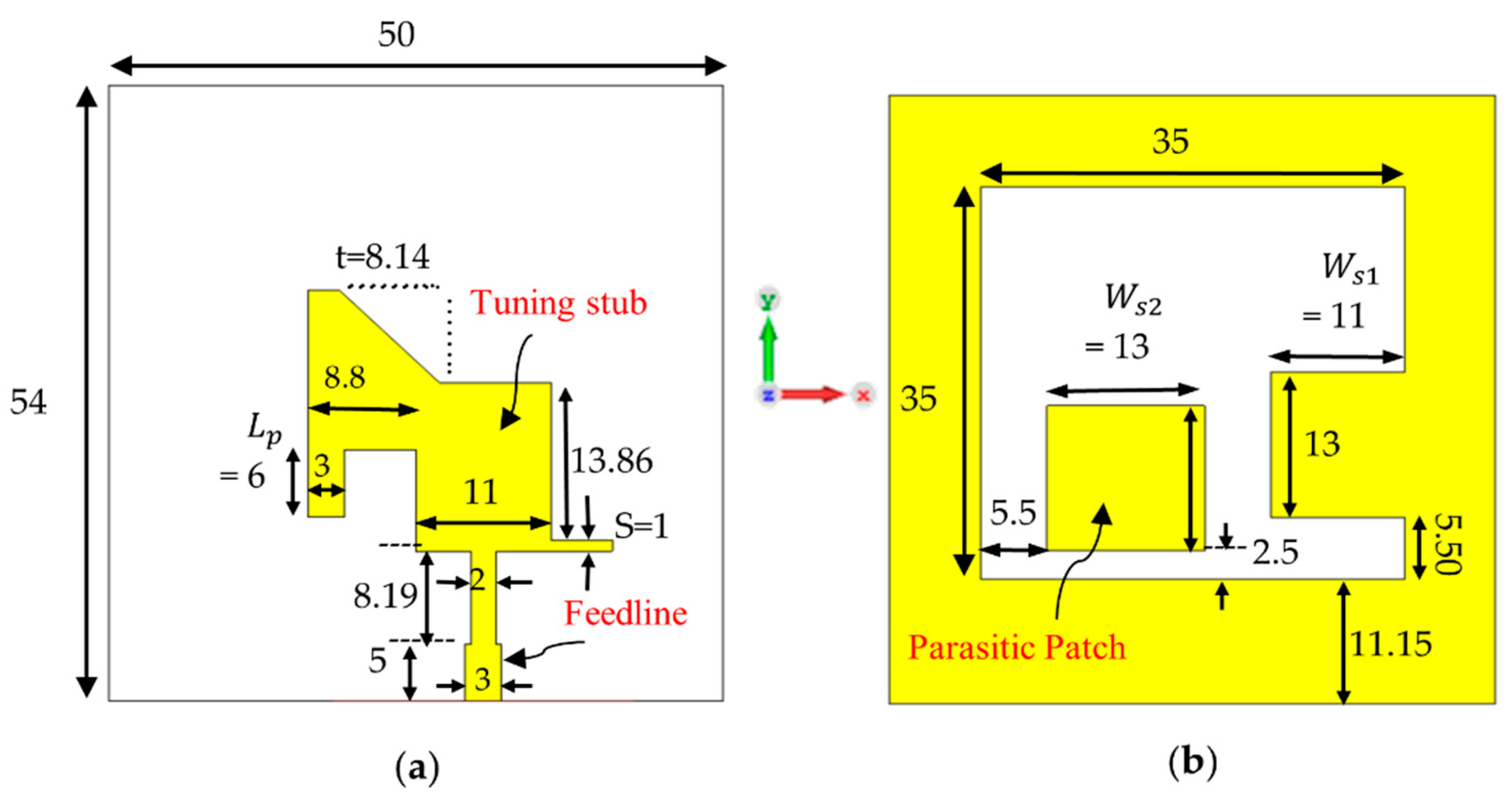
2. Antenna Structure
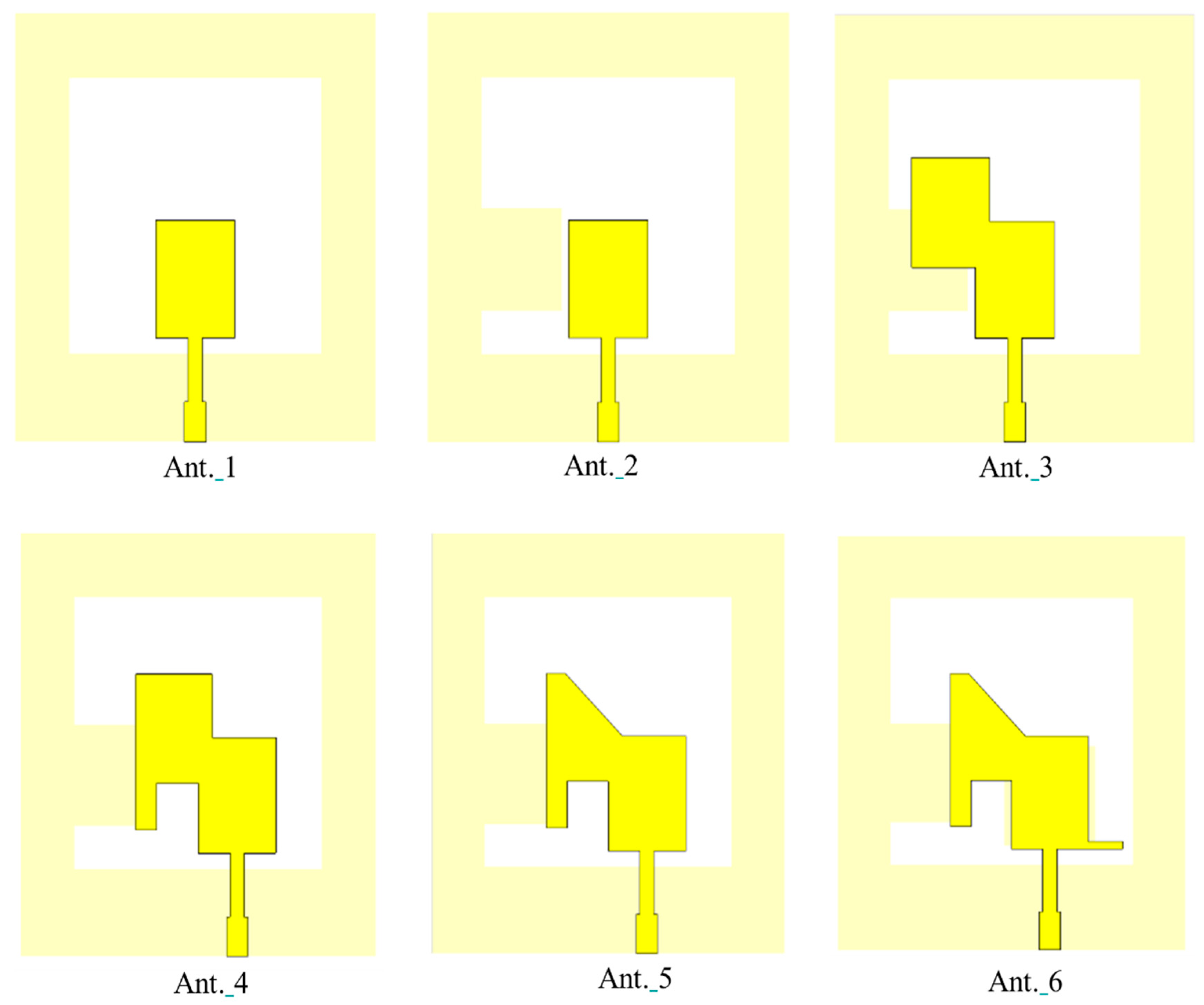
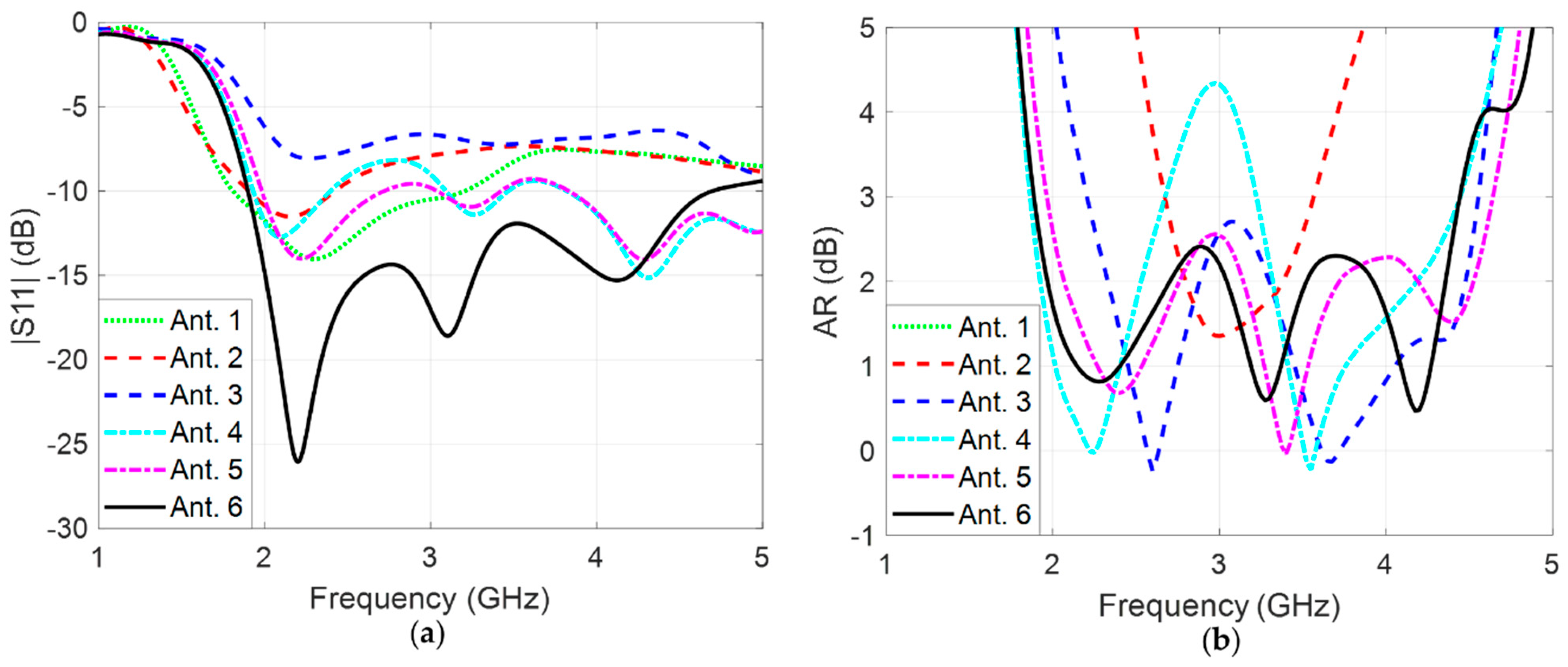
3. Design Steps
- -
- 5G sub-6 GHz (3.4–3.8 GHz), which requires compact size devices such as smartphones.
- -
- IoT systems and Wi-Fi 6E (2.4–5 GHz), which also require small-sized devices with a wide range of frequencies.
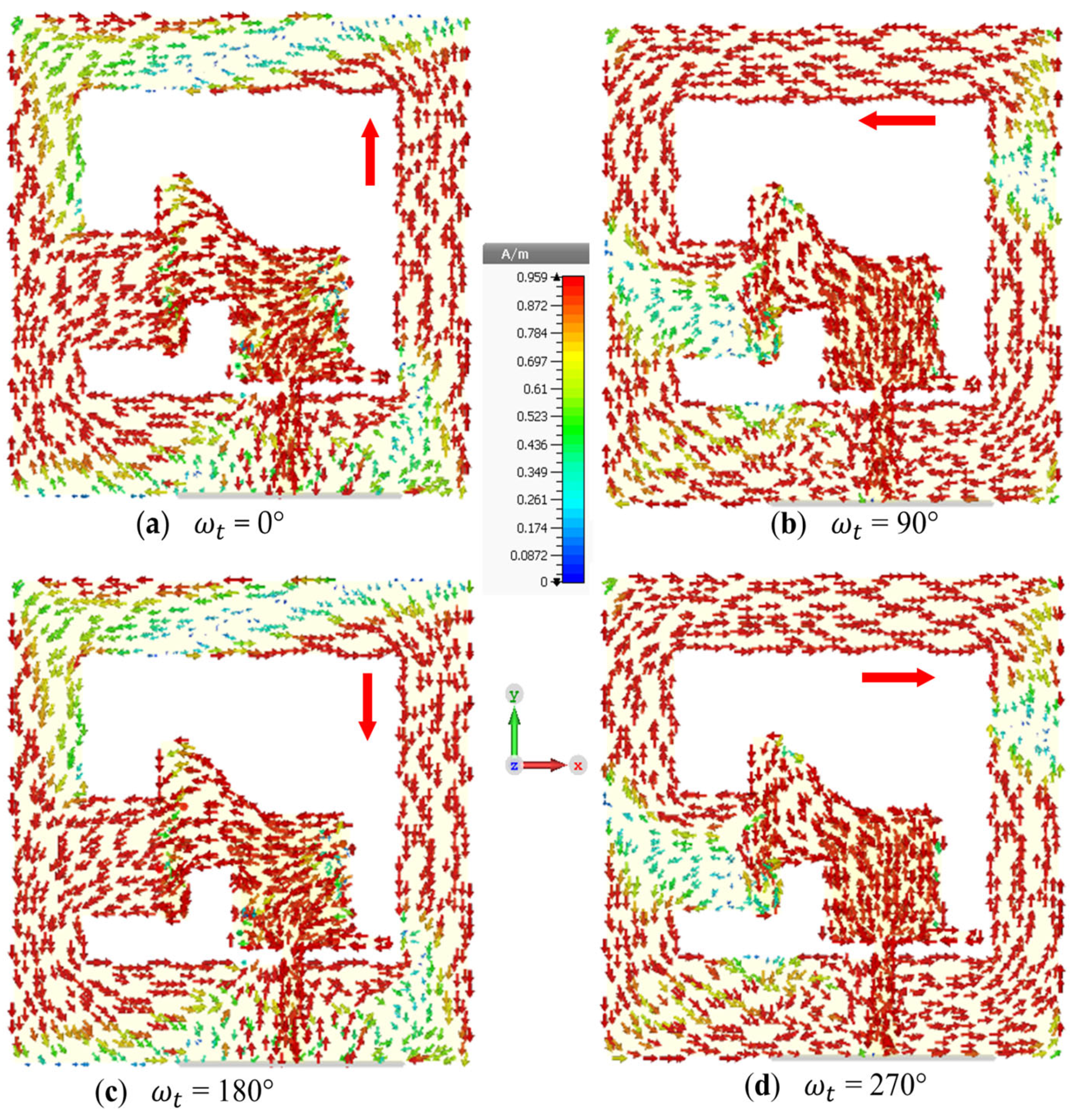
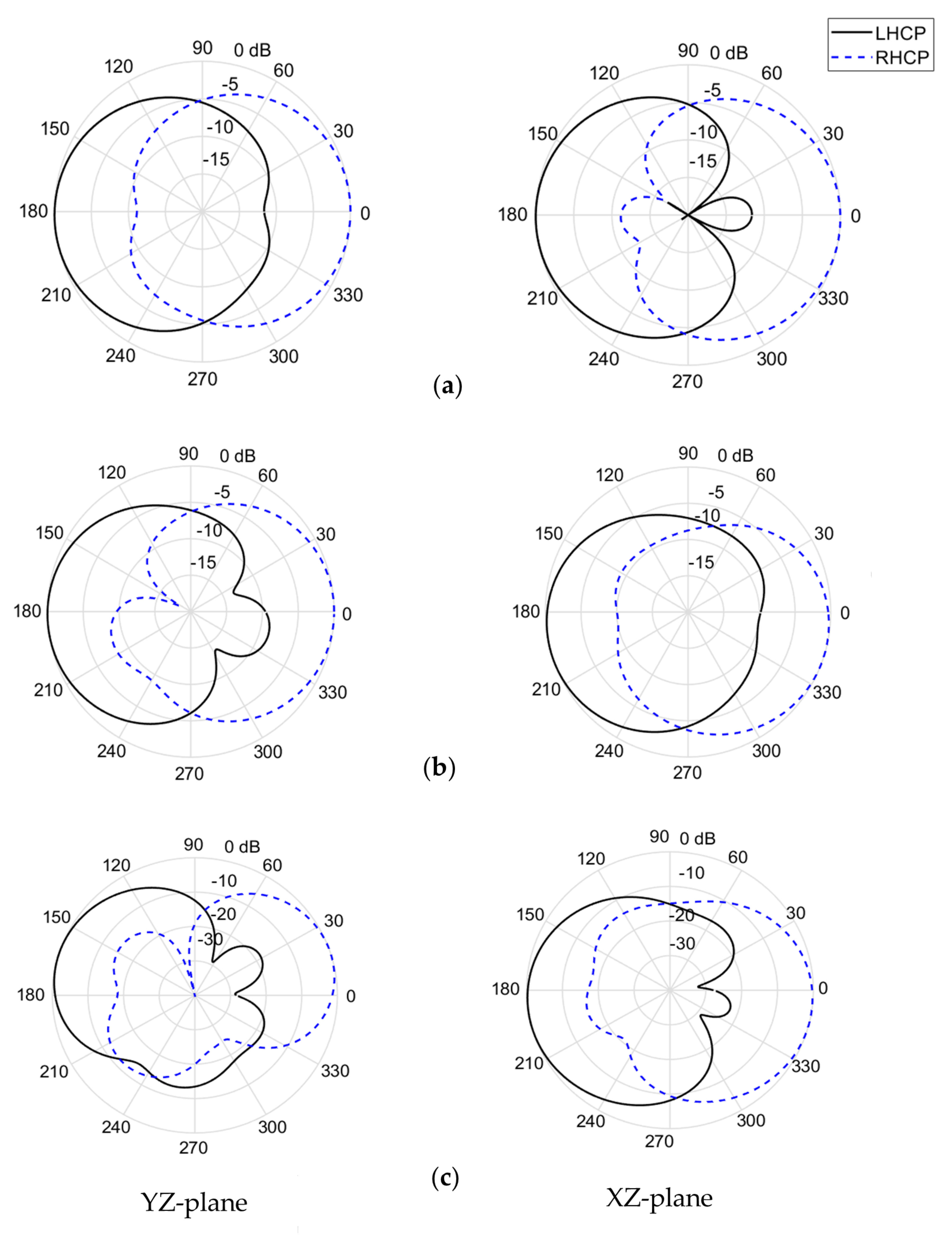
4. Circular Polarization Generation Mechanism
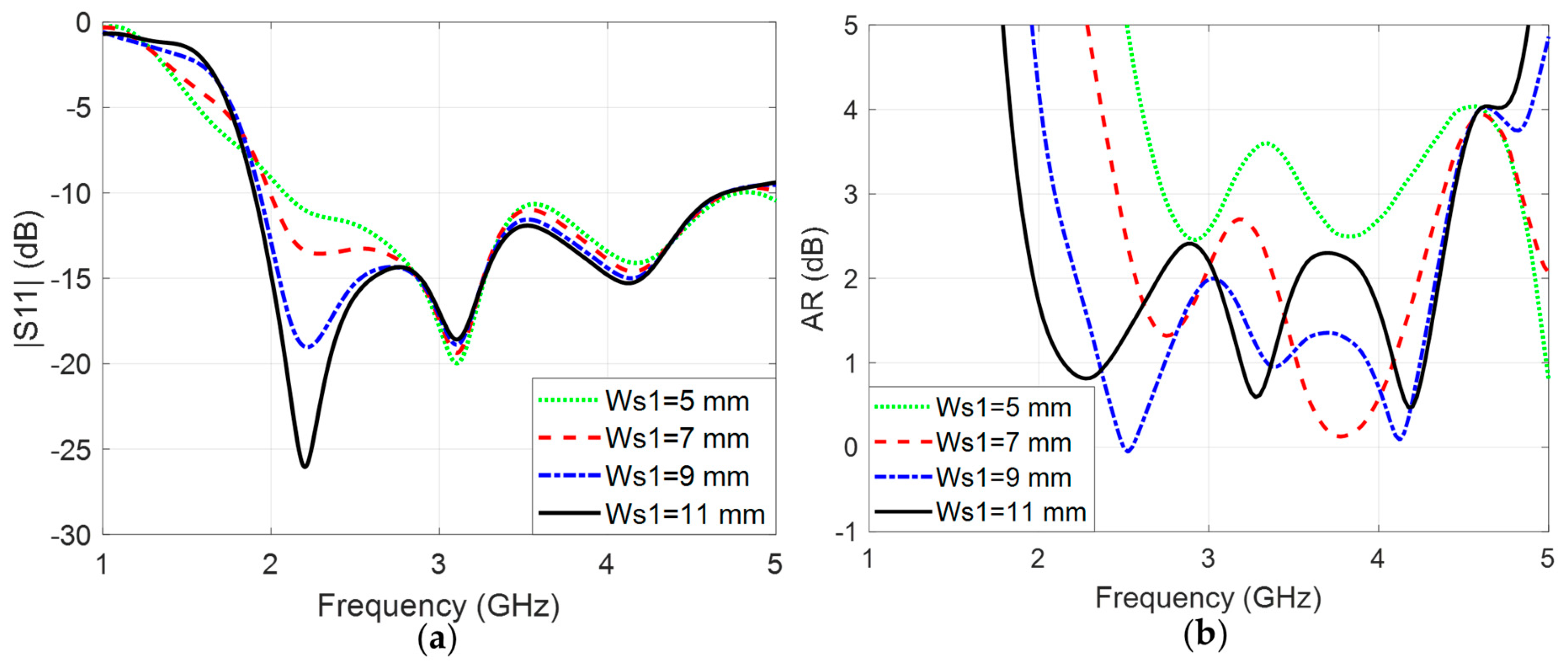
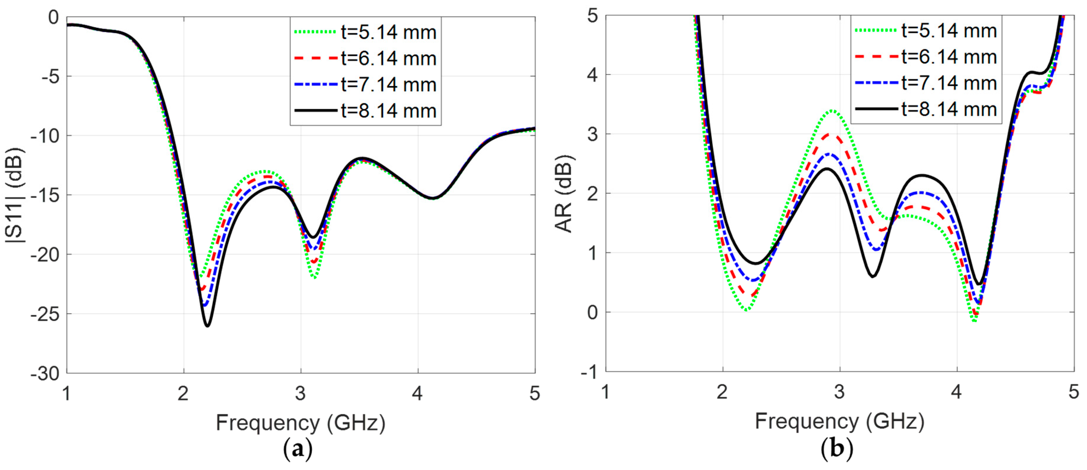
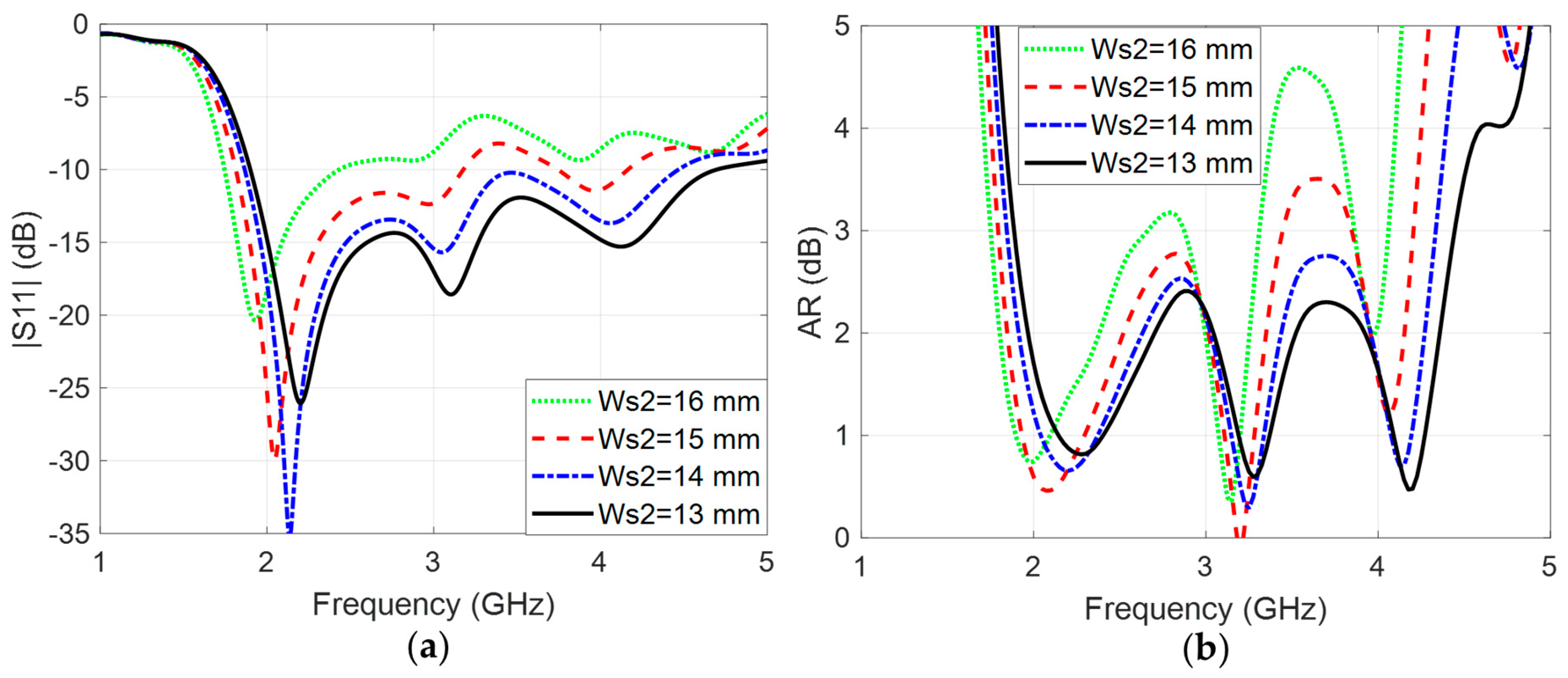
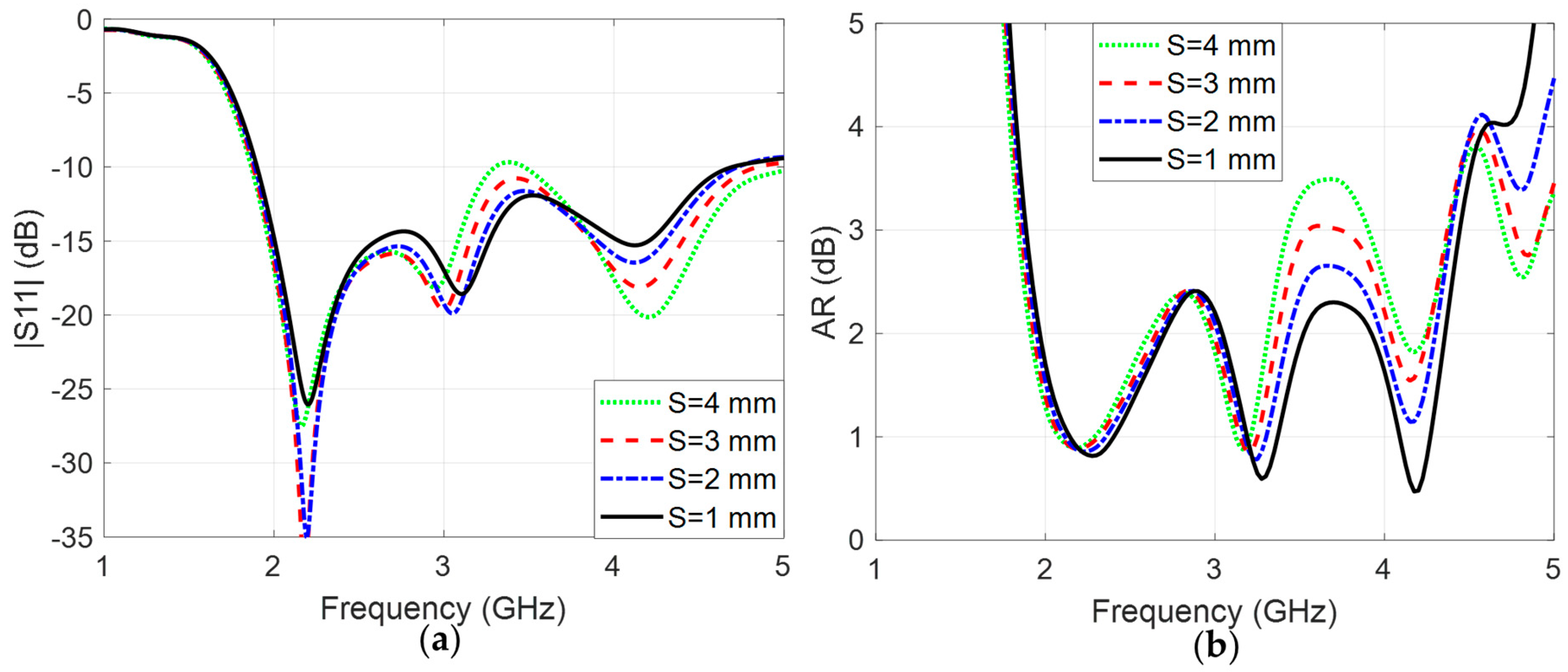
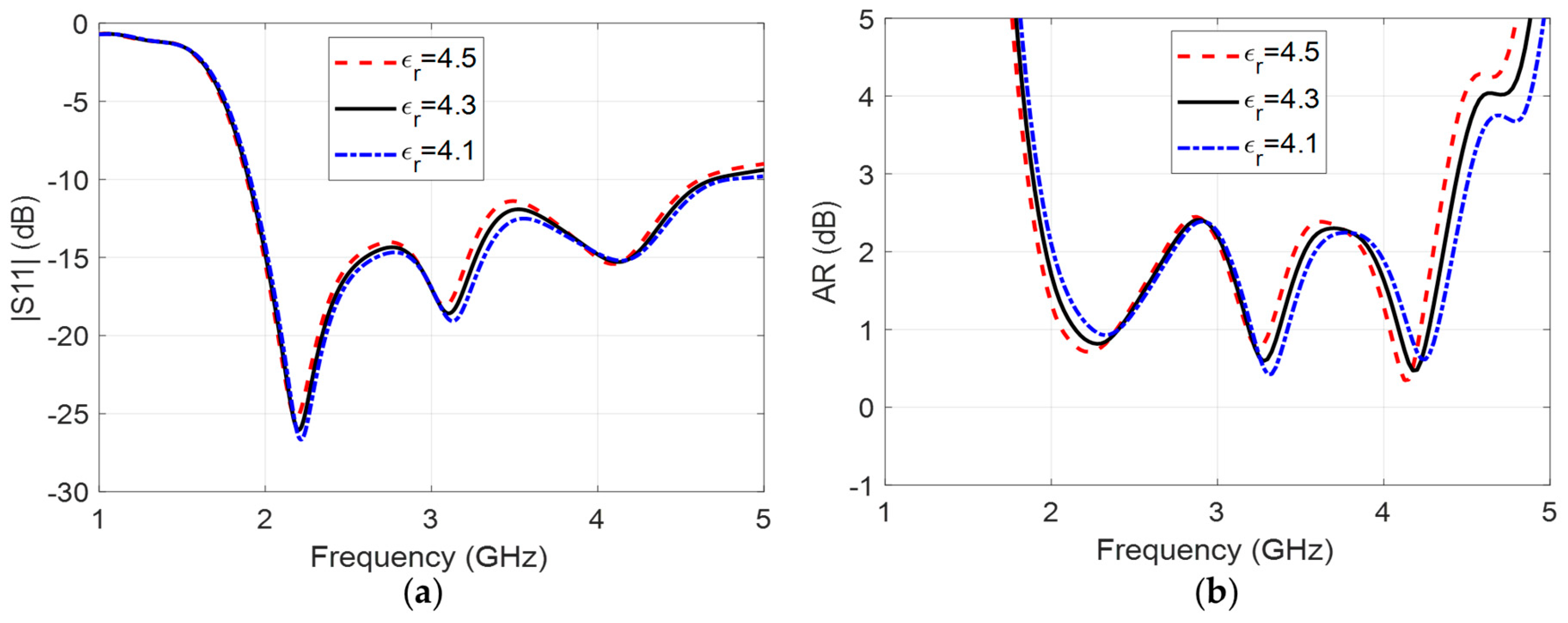
5. Parametric Study
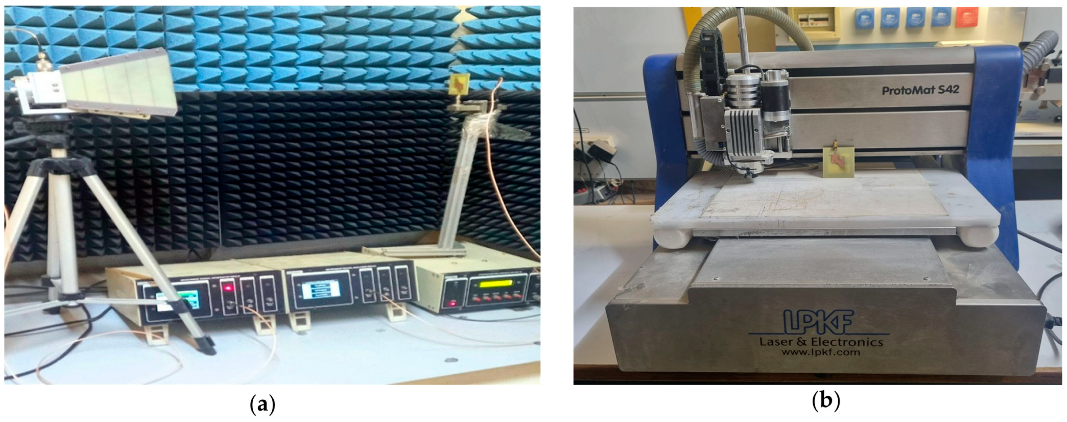
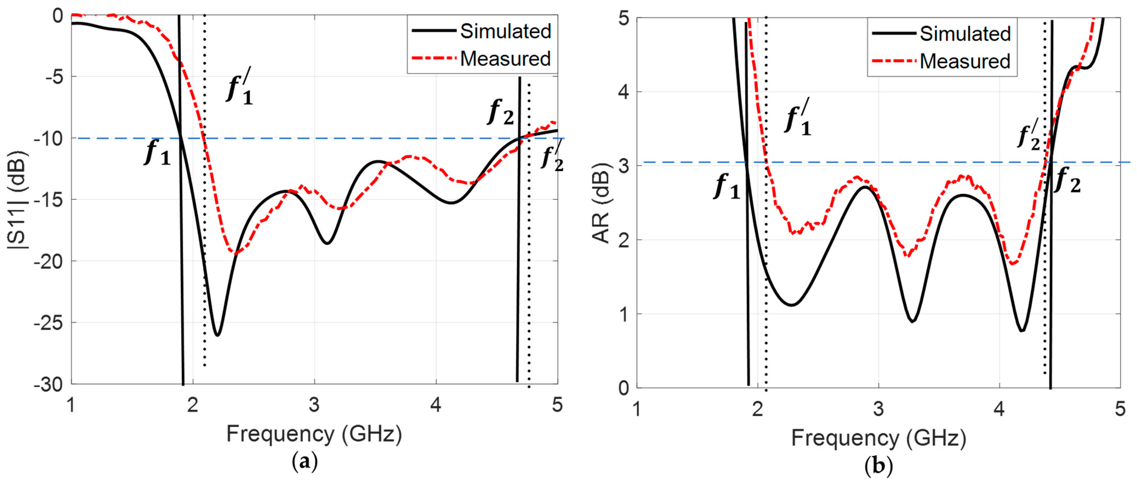
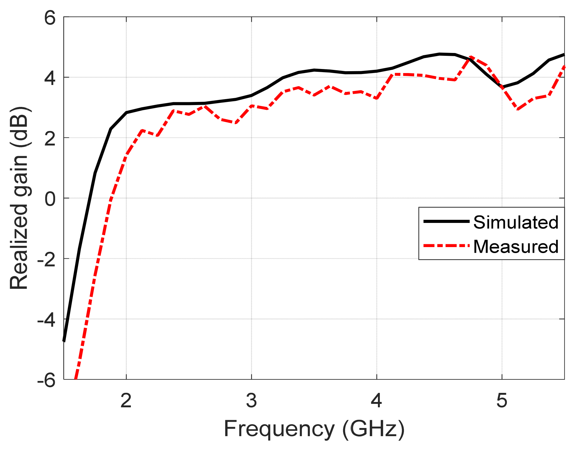
6. Measured Results
7. Conclusions
Author Contributions
Funding
Institutional Review Board Statement
Informed Consent Statement
Data Availability Statement
Conflicts of Interest
References
- Gao, S.S.; Luo, Q.; Zhu, F. Circularly Polarized Antennas; John Wiley & Sons: Hoboken, NJ, USA, 2014. [Google Scholar]
- Guha, D.; Kumar, C.; Biswas, S. Defected Ground Structure (DGS) Based Antennas: Design Physics, Engineering, and Applications; John Wiley & Sons: Hoboken, NJ, USA, 2022. [Google Scholar]
- Alnahwi, F.M.; Al-Yasir, Y.I.; See, C.H.; Abd-Alhameed, R.A. Single-element and MIMO circularly polarized microstrip antennas with negligible back radiation for 5G mid-band handsets. Sensors 2022, 22, 3067. [Google Scholar] [CrossRef] [PubMed]
- Mohammed, A.H.; Alnahwi, F.M.; Al-Yasir, Y.I. A Circularly Polarized Microstrip Antenna with Dual Circular Polarization Using a 90° Hybrid Coupler and Proximity-Coupled Feeding for LTE 43 5G Applications. Appl. Sci. 2024, 14, 11877. [Google Scholar] [CrossRef]
- Sabran, M.I.; Abdul Rahim, S.K.; Leow, C.Y.; Soh, P.J.; Chew, B.W.; Vandenbosch, G.A. Compact circularly polarized truncated square ring slot antenna with suppressed higher resonances. PLoS ONE 2017, 12, e0172162. [Google Scholar] [CrossRef] [PubMed]
- Noghabaei, S.M.; Rahim, S.; Soh, P.; Abedian, M.; Vandenbosch, G. A dual-band circularly-polarized patch antenna with a novel asymmetric slot for WiMAX application. Radioengineering 2013, 22, 291–295. Available online: http://www.radioeng.cz/fulltexts/2013/13_01_0291_0295.pdf (accessed on 7 May 2025).
- Pirooj, A.; Naser-Moghadasi, M.; Zarrabi, F.B.; Sharifi, A. A dual band slot antenna for wireless applications with circular polarization. Prog. Electromagn. Res. C 2017, 71, 69–77. [Google Scholar] [CrossRef]
- Agarwal, K.; Dutta, S. Miniaturized Circularly Polarized Stacked Patch Antenna on Reactive Impedance Surface for Dual-Band ISM and WiMAX Applications. Int. J. Antennas Propag. 2015, 2015, 938565. [Google Scholar] [CrossRef]
- Remya, V.R.; Abraham, M.; Parvathy, A.; Mathew, T. Multiband circularly polarised microstrip patch antenna with minkowski fractal slot for wireless communications. Prog. Electromagn. Res. C 2021, 116, 65–80. [Google Scholar] [CrossRef]
- Gharbia, I.; Ullah, A.; Alnahwi, F.; Salisu, A.; Oguntala, G.; Ngala, M.; Abd-Alhameed, R. Multi-band UHF RFID Reader Antenna Design. In Proceedings of the 3rd International Multi-Disciplinary Conference: “Integrated Sciences and Technologies”, IMDC-IST 2023, Yola, Nigeria, 25–27 October 2023. [Google Scholar] [CrossRef]
- Ta, S.X.; Nguyen, V.C.; Nguyen-Thi, B.-T.; Hoang, T.B.; Nguyen, A.N.; Nguyen, K.K.; Dao-Ngoc, C. Wideband dual-circularly polarized antennas using aperture-coupled stacked patches and single-section hybrid coupler. IEEE Access 2022, 10, 21883–21891. [Google Scholar] [CrossRef]
- Kumar, S.; Lee, G.H.; Kim, D.H.; Choi, H.C.; Kim, K.W. Dual circularly polarized planar four-port MIMO antenna with wide axial-ratio bandwidth. Sensors 2020, 20, 5610. [Google Scholar] [CrossRef]
- Al-Yasir, Y.I.; Abdulkhaleq, A.M.; Parchin, N.O.; Elfergani, I.T.; Rodriguez, J.; Noras, J.M.; Abd-Alhameed, R.A.; Rayit, A.; Qahwaji, R. Green and highly efficient MIMO transceiver system for 5G heterogenous networks. IEEE Trans. Green Commun. Netw. 2021, 6, 500–511. [Google Scholar] [CrossRef]
- Alsariera, H.; Zakaria, Z.; Isa, A.; Al-Heety, O.S.; Zeain, M.; Abu-Khadrah, A.I.; Alahnomi, R.; Mabrok, M. Compact CPW-fed broadband circularly polarized monopole antenna with inverted L-shaped strip and asymmetric ground plane. Prz. Elektrotechniczny 2020, 4, 53–56. [Google Scholar] [CrossRef]
- Ding, K.; Guo, Y.-X.; Gao, C. CPW-fed wideband circularly polarized printed monopole antenna with open loop and asymmetric ground plane. IEEE Antennas Wirel. Propag. Lett. 2016, 16, 833–836. [Google Scholar] [CrossRef]
- Alnahwi, F.M.; Al-Yasir, Y.I.; Ali, N.T.; Gharbia, I.; See, C.H.; Abd-Alhameed, R.A. A compact wideband circularly polarized planar monopole antenna with axial ratio bandwidth entirely encompassing the antenna bandwidth. IEEE Access 2022, 10, 81828–81835. [Google Scholar] [CrossRef]
- Tang, H.; Wang, K.; Wu, R.; Yu, C.; Zhang, J.; Wang, X. A novel broadband circularly polarized monopole antenna based on C-shaped radiator. IEEE Antennas Wirel. Propag. Lett. 2016, 16, 964–967. [Google Scholar] [CrossRef]
- Ding, K.; Gao, C.; Yu, T.; Qu, D. Broadband C-shaped circularly polarized monopole antenna. IEEE Trans. Antennas Propag. 2014, 63, 785–790. [Google Scholar] [CrossRef]
- Gyasi, K.O.; Wen, G.; Inserra, D.; Huang, Y.; Li, J.; Ampoma, A.E.; Zhang, H. A compact broadband cross-shaped circularly polarized planar monopole antenna with a ground plane extension. IEEE Antennas Wirel. Propag. Lett. 2018, 17, 335–338. [Google Scholar] [CrossRef]
- Iqbal, K.; Khan, Q.U.; Ahmed, Z. Compact high gain wideband circularly polarized non-uniform metasurface antenna through improved mode coupling. IEEE Open J. Antennas Propag. 2024, 5, 1432–1439. [Google Scholar] [CrossRef]
- Xu, Y.; Wang, Z.; Dong, Y. Circularly polarized slot antennas with dual-mode elliptic cavity. IEEE Antennas Wirel. Propag. Lett. 2020, 19, 715–719. [Google Scholar] [CrossRef]
- Han, L.; Chai, K.; Han, G.; Chen, X.; Zhang, W. Compact broadband circularly polarized slot antenna with artificial magnetic conductor reflector. Int. J. RF Microw. Comput. Aided Eng. 2022, 32, e23534. [Google Scholar] [CrossRef]
- He, W.; Hong, J.; Ren, Y.; Deng, Y.; Wang, X.; Fang, X. A High Gain Circularly Polarized Slot Antenna Array for 5G Millimeter-Wave Applications. Sensors 2024, 24, 6175. [Google Scholar] [CrossRef]
- Xia, C.; Diao, S.; Yin, W.; Huang, Z.; Wang, L.; Lei, D.; Burghignoli, P. A Compact Wideband Circularly Polarized Microstrip Slot Antenna with Parasitic Elements. Int. J. Antennas Propag. 2021, 2021, 5214891. [Google Scholar] [CrossRef]
- Alnahwi, F.M.; Islam, N.E. A generalized concept for band notch generation in ultra-wide band antennas. Prog. Electromagn. Res. C 2014, 54, 179–185. [Google Scholar] [CrossRef]
- Xu, R.; Li, J.-Y.; Liu, J.; Zhou, S.-G.; Wei, K.; Xing, Z.-J. A simple design of compact dual-wideband square slot antenna with dual-sense circularly polarized radiation for WLAN/Wi-Fi communications. IEEE Trans. Antennas Propag. 2018, 66, 4884–4889. [Google Scholar] [CrossRef]
- Fu, Q.; Feng, Q.; Chen, H. Design and optimization of CPW-fed broadband circularly polarized antenna for multiple communication systems. Prog. Electromagn. Res. Lett. 2021, 99, 65–75. [Google Scholar] [CrossRef]
- Chen, Z.F.; Xu, B.; Hu, J.; He, S. A CPW-fed broadband circularly polarized wide slot antenna with modified shape of slot and modified feeding structure. Microw. Opt. Technol. Lett. 2016, 58, 1453–1457. [Google Scholar] [CrossRef]
- Krishna, R.R.; Kumar, R.; Kushwaha, N. A circularly polarized slot antenna for high gain applications. AEU Int. J. Electron. Commun. 2014, 68, 1119–1128. [Google Scholar] [CrossRef]
- Ullah, U.; Koziel, S.; Mabrouk, I.B. A simple-topology compact broadband circularly polarized antenna with unidirectional radiation pattern. IEEE Antennas Wirel. Propag. Lett. 2019, 18, 2612–2616. [Google Scholar] [CrossRef]
- Wang, L.; Yao, B.; Fang, W.; Huang, C.; Huang, Y.; En, Y. New Circular-Slot Circularly Polarized Antenna with Modified Characteristic. Int. J. Antennas Propag. 2022, 2022, 5458069. [Google Scholar] [CrossRef]
- Samsuzzaman, M.; Islam, M.T. Circularly polarized broadband printed antenna for wireless applications. Sensors 2018, 18, 4261. [Google Scholar] [CrossRef]
- Sitompul, P.P.; Sri Sumantyo, J.T.; Kurniawan, F.; Nasucha, M. Axial ratio and gain enhancement of a circular-ring slot antenna using a pair of asymmetrical rectangular slots and a parasitic patch for a radio beacon on a nanosatellite. Aerospace 2019, 6, 39. [Google Scholar] [CrossRef]
- Singh, A.K.; Patil, S.; Kanaujia, B.K.; Pandey, V.K.J.M.; Letters, O.T. A novel printed circularly polarized asymmetric wide slot antenna for digital cellular system. Microw. Opt. Technol. Lett. 2020, 62, 1438–1447. [Google Scholar] [CrossRef]
- Alnahwi, F.M.; Al-Yasir, Y.I.; Ali, N.T.; Gharbia, I.; Abdullah, A.S.; Hu, Y.F.; Abd-Alhameed, R.A. A compact broadband circularly polarized wide-slot antenna with axial ratio bandwidth encompassing LTE 42 and LTE 43 standards of 5G mid-band. IEEE Access 2023, 11, 2012–2022. [Google Scholar] [CrossRef]
- Parvathy, A.; Ajay, V.; Thomaskutty, M. Circularly polarized split ring resonator loaded slot antenna. Adv. Electromagn. 2018, 7, 1–6. [Google Scholar] [CrossRef]
- Liu, Y.; Cai, S.T.; Xiong, X.M.; Li, W.J.; Yang, J. A novel wideband circularly polarized modified square-slot antenna with loaded strips. Int. J. RF Microw. Comput. Aided Eng. 2019, 29, e21873. [Google Scholar] [CrossRef]
- Wen-Wen, L.; Zhen-Hua, C.; Zhi, W. New broadband circularly polarized antenna with an inverted F-shaped feedline. Int. J. RF Microw. Comput. Aided Eng. 2020, 30, e22313. [Google Scholar] [CrossRef]
- Chen, Q.; Zhang, H.; Yang, L.-C.; Li, B.-B.; Min, X.-L. Wideband inverted-L microstrip-via-Fed circularly polarized antenna with asymmetrical ground for WLAN/Wimax applications. Frequenz 2018, 72, 333–341. [Google Scholar] [CrossRef]
- Wang, L.; Fang, W.; En, Y.; Huang, Y.; Shao, W.; Yao, B. A new broadband circularly polarized square-slot antenna with low axial ratios. Int. J. RF Microw. Comput.-Aided Eng. 2019, 29, e21502. [Google Scholar] [CrossRef]
- Zhang, H.; Jiao, Y.-C.; Lu, L.; Zhang, C. Broadband circularly polarized square-ring-loaded slot antenna with flat gains. IEEE Antennas Wirel. Propag. Lett. 2016, 16, 29–32. [Google Scholar] [CrossRef]
- Chen, Q.; Yang, J.; He, C.; Zhang, D.; Huang, S.; Wang, M.; Yu, F.; Dai, G. Wideband Circularly Polarization and High-Gain of a Slot Patch Array Antenna Realized by a Hybrid Metasurface. Sensors 2024, 24, 3510. [Google Scholar] [CrossRef]
- Aldrigo, M.; Tasolamprou, A.C.; Vasilache, D.; Kafesaki, M.; Iordanescu, S.; Nastase, F.; Dragoman, M. Tunable microwave dual-band patch antenna through integration of metamaterials and nanoscale ferroelectrics. Phys. Rev. Appl. 2023, 20, 044067. [Google Scholar] [CrossRef]
- Wicaksono, S.A.; Edwar; Ryanu, H.H.; Nugroho, B.S.; Nur, L.O. Microstrip patch antenna miniaturization using metamaterial structure for 5G communication. In Proceedings of the 5th International Conference on Electrical, Electronic, Communication and Control Engineering (ICEECC 2021), Johor Bahru, Malaysia, 15–16 December 2021; p. 030009. [Google Scholar] [CrossRef]
- Ramzan, M.; Topalli, K. A miniaturized patch antenna by using a CSRR loading plane. Int. J. Antennas Propag. 2015, 2015, 495629. [Google Scholar] [CrossRef]
- Thanikonda, R.; Faenzi, M.; Toccafondi, A.; Martini, E.; Maci, S. Dual Circularly Polarized Metasurface Antenna Based on Inward and Outward Surface Wave Duplexing. IEEE Trans. Antennas Propag. 2025, 73, 2700–2712. [Google Scholar] [CrossRef]
- Zhao, C.; Shen, D. Low-RCS High-Gain Broadband Substrate-Integrated Waveguide Antenna Based on Elliptical Polarisation Conversion Metasurface. IET Microw. Antennas Propag. 2025, 19, e70016. [Google Scholar] [CrossRef]
- Wu, Q.; Chen, W.; Yu, C.; Wang, H.; Hong, W. Machine-learning-assisted optimization for antenna geometry design. IEEE Trans. Antennas Propag. 2024, 72, 2083–2095. [Google Scholar] [CrossRef]
- Al-Abbasi, M.; Abdul Latef, T. Wideband circularly polarized fractal antenna with SSRR metasurface for 5G applications. Int. J. Electr. Comput. Eng. Syst. 2024, 15, 89–98. [Google Scholar] [CrossRef]
- Shrimal, S.; Agrawal, R.; Sharma, I.B.; Sharma, M. Dual wideband circularly polarized reconfigurable antenna using gap loaded annular ring. AEU Int. J. Electron. Commun. 2024, 178, 155296. [Google Scholar] [CrossRef]
- Rasool, N.; Huang, K.; Muhammad, A.B.; Liu, Y. A wideband circularly polarized slot antenna with antipodal strips for WLAN and C-band applications. Int. J. RF Microw. Comput. Aided Eng. 2019, 29, e21945. [Google Scholar] [CrossRef]
- Studio, C.M. CST Studio suite. Computer Simulation 2010. Available online: https://www.3ds.com/products/simulia/cst-studio-suite (accessed on 7 May 2025).
- Räisänen, A.V.; Lehto, A. Radio Engineering for Wireless Communication and Sensor Applications; Artech House: Norwood, MA, USA, 2003; pp. 284–287. [Google Scholar]
- He, W.; He, Y.; Wong, S.W.; Liao, C.H. A wideband circularly polarized S-shaped slot antenna. Int. J. RF Microw. Comput. Aided Eng. 2021, 31, e22612. [Google Scholar] [CrossRef]
- Dwivedi, A.K.; Narayanaswamy, N.K.; Penmatsa, K.K.V.; Singh, S.K.; Sharma, A.; Singh, V. Circularly polarized printed dual port MIMO antenna with polarization diversity optimized by machine learning approach for 5G NR n77/n78 frequency band applications. Sci. Rep. 2023, 13, 13994. [Google Scholar] [CrossRef]
- Ellis, M.S.; Owusu-Achiaw, N.A.; Osei, S.A.; Nakojah, D. Design of a circularly polarized printed open-slot antenna using theory of characteristic modes. Microw. Opt. Technol. Lett. 2023, 65, 1677–1685. [Google Scholar] [CrossRef]
- Hao, L.; Fan, C.; Wang, H.; Li, B.; Yin, W. Novel square slot circularly polarized antenna with broadband characteristics. Int. J. RF Microw. Comput. Aided Eng. 2022, 32, e22921. [Google Scholar] [CrossRef]
- Wang, C.; Xu, G.; Li, M.; Huang, Z.; Ren, X.; Wang, J.; Wu, X. Ultra-wideband millimeter-wave bidirectional circularly polarized monopole antenna array using a sequentially rotated feeding technique. IEEE Trans. Antennas Propag. 2022, 71, 1117–1122. [Google Scholar] [CrossRef]


| Ref. | Antenna Dimensions | −10 dB BW % | 3 dB ARBW % | Peak Gain (dB) | Substrate Type | Application | CP Type | Efficiency % |
|---|---|---|---|---|---|---|---|---|
| [31] | 0.66λ × 0.66λ × 0.010λ | 110.0 | 75.7 | 4.52 | RO430B | Wi-Fi/WLAN | RHCP | ----- |
| [33] | 0.73λ × 0.69λ × 0.011λ | 47.27 | 35.79 | 5 | ----- | WiMAX | LHCP | ----- |
| [34] | 0.277λ × 0.264λ × 0.010λ | 20.73 | 6.84 | 3 | FR4 | Digital cellular systems | RHCP | 95 |
| [35] | 0.41λ × 0.36λ × 0.019λ | 16.2 | 12.2 | 3.1 | FR4 | LTE 5G (band 42/43) | LHCP | ----- |
| [36] | 0.34λ × 0.49λ × 0.013λ | 10.48 | 10.48 | 3.8 | FR4 | WLAN | LHCP | ----- |
| [51] | 0.40λ × 0.40λ × 0.02λ | 60.1 | 54.54 | 6 | Rogers 5880 | WLAN/C-band | LHCP | 87 |
| [54] | 0.93λ × 0.93λ × 0.01λ | 68.1 | 57.8 | 5.4 | FR4 | ISM band | LHCP | ----- |
| [55] | 0.75λ × 0.75 × 0.01λ | 33.3 | 40 | 4 | Rogers 5880 | 5G NR (n77/n78) | RHCP | ----- |
| [56] | 0.37λ × 0.37λ × 0.024λ | 125 | 61 | 4.3 | FR4 | Sub-6 GHz 5G | LHCP | 90 |
| [57] | 0.87λ × 0.87λ × 0.02λ | 69.2 | 59 | 4.3 | FR4 | Sub-6 GHz 5G | RHCP | 75 |
| This work | 0.39λ × 0.36λ × 0.011λ | 78 | 71.6 | 4.68 | FR4 | Sub-6 GHz 5G | RHCP | 93 |
Disclaimer/Publisher’s Note: The statements, opinions and data contained in all publications are solely those of the individual author(s) and contributor(s) and not of MDPI and/or the editor(s). MDPI and/or the editor(s) disclaim responsibility for any injury to people or property resulting from any ideas, methods, instructions or products referred to in the content. |
© 2025 by the authors. Licensee MDPI, Basel, Switzerland. This article is an open access article distributed under the terms and conditions of the Creative Commons Attribution (CC BY) license (https://creativecommons.org/licenses/by/4.0/).
Share and Cite
Mohammed, A.H.; Alnahwi, F.M.; Al-Yasir, Y.I.A.; Ekpo, S.C. A Miniaturized RHCP Slot Antenna for Wideband Applications Including Sub-6 GHz 5G. Technologies 2025, 13, 254. https://doi.org/10.3390/technologies13060254
Mohammed AH, Alnahwi FM, Al-Yasir YIA, Ekpo SC. A Miniaturized RHCP Slot Antenna for Wideband Applications Including Sub-6 GHz 5G. Technologies. 2025; 13(6):254. https://doi.org/10.3390/technologies13060254
Chicago/Turabian StyleMohammed, Atyaf H., Falih M. Alnahwi, Yasir I. A. Al-Yasir, and Sunday C. Ekpo. 2025. "A Miniaturized RHCP Slot Antenna for Wideband Applications Including Sub-6 GHz 5G" Technologies 13, no. 6: 254. https://doi.org/10.3390/technologies13060254
APA StyleMohammed, A. H., Alnahwi, F. M., Al-Yasir, Y. I. A., & Ekpo, S. C. (2025). A Miniaturized RHCP Slot Antenna for Wideband Applications Including Sub-6 GHz 5G. Technologies, 13(6), 254. https://doi.org/10.3390/technologies13060254