Article

Intelligent Battery Management in a Hybrid Photovoltaic Using Fuzzy Logic System

1
Department of Electronics and Computer Engineering, De La Salle University (DLSU), 2401 Taft Avenue, Malate, Manila 1004, Philippines
2
Department of Mechanical Engineering, De La Salle University (DLSU), 2401 Taft Avenue, Malate, Manila 1004, Philippines
3
Department of Manufacturing Engineering and Management, De La Salle University (DLSU), 2401 Taft Avenue, Malate, Manila 1004, Philippines
4
Faculty of Human and Digital Sciences, Liverpool Hope University, Hope Park Campus, Taggart Avenue, Liverpool L169JD, UK
*
Authors to whom correspondence should be addressed.
Technologies 2025, 13(6), 214; https://doi.org/10.3390/technologies13060214
Submission received: 25 March 2025 / Revised: 13 May 2025 / Accepted: 14 May 2025 / Published: 26 May 2025

Abstract

:
LiFePO4 batteries need a battery management system (BMS) to improve performance, extend their lifespan, and maintain safety by utilizing advanced monitoring, control, and optimization techniques. This paper presents the design, development, and implementation of an intelligent battery management system (i-BMS) that integrates the real-time monitoring and control of batteries. The system was extensively tested using multiple datasets, and the results show that the system was able to maintain battery temperature within the set range, balance the cell voltages, and distribute energy according to load prioritization. It uses a fuzzy logic system approach to effectively manage farm energy requirements. Additionally, the proposed method embedded a three-level load prioritization algorithm woven into the fuzzy rule set to allocate energy dynamically among essential, regular, and non-essential loads.

1. Introduction

Driven by the imperative to mitigate climate change, there is an increasingly global shift to renewable energy sources, a movement inspired by the United Nations’ 2030 Sustainable Development Goal to provide clean, green, sustainable, and affordable energy for all [1]. Nevertheless, despite their abundance and cost-effectiveness, renewable resources remain inherently weather-dependent and intermittent [2]. This variability underscores the critical need for efficient energy storage to maintain a consistent power supply [3]. According to Statista 2025, it is expected that by year 2031, batteries in the solar energy systems will have the second largest market share, amounting to 154.31 billion US dollars (refer to Figure 1). Among the various battery technologies available, lithium iron phosphate (LiFePO4) has emerged as the preferred choice, due to its superior performance and enhanced safety [4]. Today, this rising demand for LiFePO4 batteries is widely observed both in the automative and renewable energy industries [5].
A LiFePO4 battery has high power density, longer life span, better thermal stability, and low self-discharge rate, and is environmentally friendly, robust, and reliable, making it suitable for solar power systems. Although it offers numerous advantages, it also has some drawbacks, such as low cell voltage, typically 3.2 V, and a relatively flat discharge voltage [6]. The low cell voltage implies more batteries connected in a series to meet the 12 V, 24 V, 36 V, or more system design. Thus, a battery management system (BMS) is needed.
In any energy storage system, BMS is used for energy optimization, grid stabilization, peak shaving, and safety [7]. Primarily, the functionalities include (1) measurement and control; (2) charge and discharge control; (3) thermal control; (4) communications; (5) diagnostics, data logging, and authentication; and (6) protection [8]. It has also evolved from no management to advanced management [9]:
  • Low Management—This management level primarily involves the manual measurement and periodic monitoring of battery parameters, typically suited for single-cell lead–acid batteries. It necessitates regular manual maintenance to ensure proper operation and safety.
  • Basic Management—Provides the real-time online monitoring of essential external battery parameters, offering protection against overcharging and over-discharging scenarios. This level is suitable for managing small sets of batteries, ensuring improved reliability and lifespan through basic protective functionalities.
  • Enhanced Management—Explicitly designed for onboard battery systems in electric vehicles (EVs), this advanced management level encompasses comprehensive battery modeling, precise state estimation, sophisticated fault diagnosis, and optimized control strategies. It is tailored to handle battery modules, significantly enhancing performance, safety, and overall system efficiency.
The continued development of battery technology has led to intelligent battery management systems. This emerging technology incorporates artificial intelligence, big data, IoT, wireless sensing network (WSN), cloud computing, and predictive models [10]. Hence, this convergence of digital technologies led to the development of this study.
The primary objective of this study was to design and develop an intelligent battery management system for hybrid photovoltaic (PV) technology, using computational intelligence (CI) techniques to optimize energy distribution and utilization. Specifically, the research aimed to
  • Develop a comprehensive monitoring system that tracks and analyzes energy generation, distribution, and priority-based load management in real time;
  • Design and implement a real-time intelligent battery management framework using advanced sensors integrated with computational intelligence algorithms to enhance energy distribution efficiency and optimize utilization;
  • Evaluate the overall performance of the intelligent battery management system (i-BMS) by comparing the energy generated versus energy demand utilization.
This study is presented as follows: Section 2 discusses the related studies and works on battery management systems; Section 3 covers the system overview and fuzzy logic application; Section 4 includes MATLAB R2024b simulation; Section 5 shows the results and discussion; and, lastly, Section 6 presents the conclusion and recommendations.

2. Review of Related Studies and Works

Recent studies show significant development of BMS in different applications. It has dramatically improved and has impacted on applications such as hybrid photovoltaic (PV) systems. The Scopus keyword search (2021–present) for “Battery AND Management AND System” shows a rapidly expanding field centered on topics like state-of-charge (SOC) estimation, state-of-health (SOH) monitoring, and advanced control strategies [11,12,13]. Figure 2 emphasizes battery management systems as a highly interdisciplinary area, linking battery health and thermal management with AI and ML, IoT integration, and cybersecurity concerns [14,15].

2.1. BMS: An Overview

A system that has software and hardware elements designed to ensure that batteries function within the safe operating region [16]. BMS combines monitoring, controlling, and fault diagnosis to optimize battery operation, specifically in applications that require stable, reliable, and efficient energy storage. Numerous studies have been conducted to further improve BMS’s performance from zero to an intelligent, adaptive type of battery management. The published articles from the IEEE Xplore digital library related to intelligent BMS numbered 5792 conferences, 1144 journals, 98 magazines, 41 books, 34 early access articles, and 10 standards.
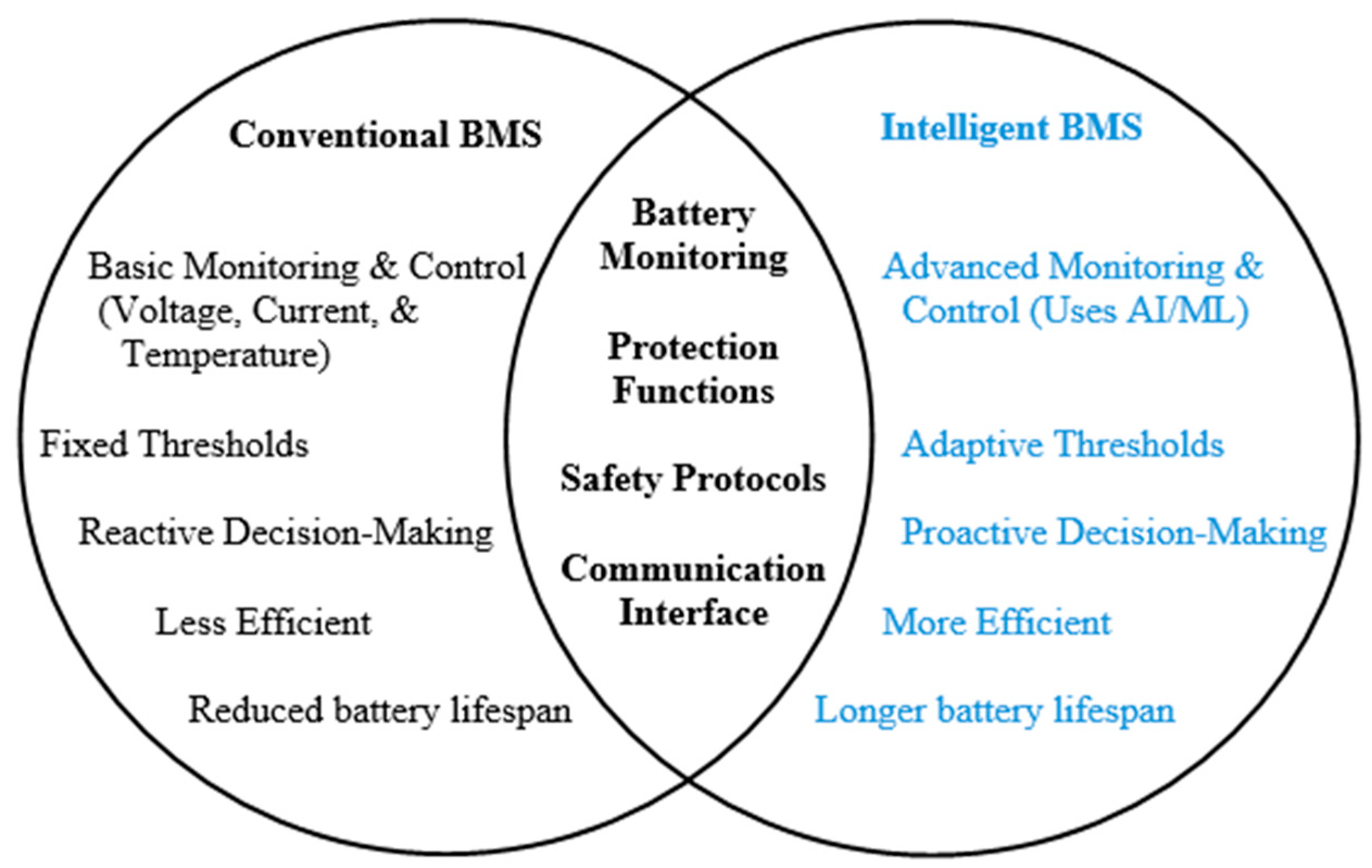
Figure 3 summarizes the comparison between conventional versus intelligent BMS. Conventional BMS focuses on basic voltage, current, and temperature monitoring, using fixed thresholds to trigger control actions. This traditional approach tends to be more reactive: decisions are made after certain limits are reached rather than anticipating issues before they occur. As a result, conventional BMS may be less efficient and can lead to a reduced overall battery lifespan [17].
In contrast, intelligent BMS incorporates advanced monitoring and control strategies, often powered by AI or machine learning. These systems utilize adaptive thresholds that change in real time based on operating conditions, enabling proactive decision-making. An intelligent BMS can improve battery performance, reduce energy losses, and prolong the lifespan by analyzing patterns and predicting potential failures or performance declines. This more sophisticated approach also enhances safety protocols and communication capabilities, ultimately resulting in a more reliable and efficient energy storage solution [18].

BMS Core Functions

Designing a BMS is difficult since it involves simultaneous functions of several integrated systems to achieve higher battery efficiency. BMS functions include monitoring, estimation, control, protection, fault diagnosis, and communication. Some of these BMS functions need sensors to measure and control battery parameters.
  • Monitoring and Sensing—A smart BMS constantly checks the battery’s condition using built-in sensors. When batteries are connected in a series, they lose their balance through repeated overcharging and over-discharging cycles. This scenario might lead to cell voltage imbalance and overheating, eventually shortening battery lifespan in the long run [19]. With this, voltage sensors are used to monitor the voltage level on each cell so it stays within safe limits and balanced [20]. Temperature sensors look for heat build-up to prevent thermal runaway. Current sensors track how much charge flows in and out, accurately showing battery use [21]. These measurements let the BMS protect the pack and extend its life.
  • State Estimation—It refers to the informational backbone of BMS, including SOC, SOH, state of energy (SOE), state of power (SOP), state of safety (SOS), state of temperature (SOT), and remaining useful life (RUL) [22]. Accurate battery state estimates are critical for optimal charging control, temperature, and overall battery health.
  • Control and Protection—The BMS can detect and keep the batteries from experiencing over-voltage (OV), under-voltage (UV), over-current (OC), short-circuit (SC), over-temperature (OT), under-temperature (UT) status and prevent further damage [23].
  • Diagnosis—It is vital for the optimal operation of batteries and is useful for identifying and detecting whenever a fault has occurred in the cell or pack. It can be used for state estimation [24], data monitoring and analysis [25], machine learning, and advanced algorithms [26], fault detection and isolation [27,28].

2.2. Smart Farming Technologies

Smart farming (SF) uses cutting-edge technologies and strategies in agriculture, including (1) data acquisition technologies, (2) data analysis and evaluation technologies, and (3) precision application technologies.
Several studies highlight key technologies used in smart farming and early adopters. They present the rapid adoption and growing importance of PV technology, IoT, and AI in agricultural settings, while also categorizing each application.
Various modern technologies are transforming traditional agricultural practices: IoT sensors for soil and crop monitoring [29,30], drones and UAVs for crop mapping and health assessment [31,32], and cloud computing for remote oversight [33], which provides vital data on farm operations. Geospatial technologies further enable precise field mapping [34], allowing farmers to tailor interventions more accurately.
From the data analysis side, machine learning enhances yield prediction and disease detection [35,36], while big data analytics improve resource management [37]. Robotics and automation streamline tasks like planting and harvesting [38], and blockchain guarantees transparency and traceability throughout the supply chain [39,40]. Finally, renewable energy sources offer cost-effective and eco-friendly power solutions [35,36], making agriculture more sustainable and efficient.

2.3. Hybrid Photovoltaic Systems

The term “photovoltaic” is derived from the Latin words “photo”, meaning “light”, and “voltaic”, meaning “energy”, which together form the word “photovoltaic” [41]. When a sufficient amount of light energy strikes the solar panel, it knocks out free electrons residing at the outermost valence shell. The panel then goes into a conduction state, producing a current.
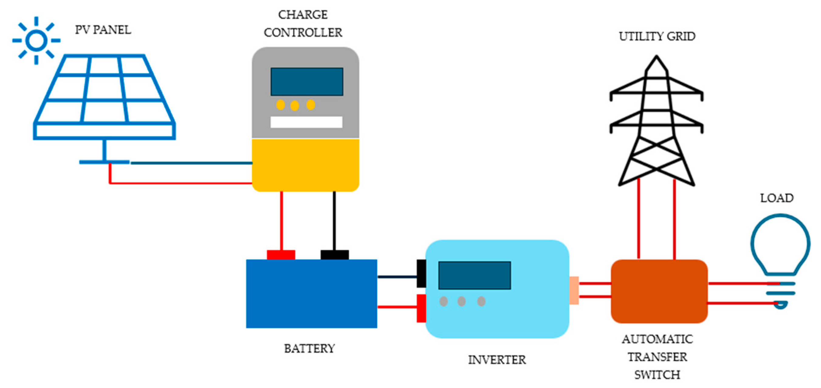
Photovoltaic (PV) technology harnesses renewable energy by arranging panels, charge controllers, batteries, and inverters. It can be implemented as an off-grid, grid-connected, or hybrid system. However, weather variations and battery degradation can compromise the reliability of a continuous power supply. Factors such as solar radiation, shading, and dust accumulation notably impact the overall system performance [42].
Figure 4 shows a hybrid PV system setup. When sunlight energy strikes the solar panel, it converts this light into electrical energy. The solar charge controller protects the battery from an overcharge state by controlling the flow of current [43]. Batteries serve as energy storage, while the inverter converts the DC signal into a usable AC signal compatible with the AC loads.

2.4. Synthesis, Research Gap, and Novel Contributions

Although fuzzy logic battery management systems (BMSs) have been studied extensively, no previous work has combined dual critical capabilities in a single, real-time hardware implementation:
  • Millisecond scale fuzzy i-BMS control running directly on embedded hardware;
  • Three-tier load prioritization (essential/regular/non-essential) integrated into the rule base.
To close this gap, the present study introduces a unified framework with two key advances:
  • Integrated i-BMS architecture that couples photovoltaic input, battery bank, and utility grid while sampling voltage, current, SOC, and cell temperature at a millisecond resolution;
  • Embedded three-level load prioritization algorithm woven into the fuzzy rule set to allocate energy dynamically among essential, regular, and non-essential loads.

3. Materials and Method

3.1. Dataset

The dataset comprises high-resolution operational records from the i-BMS battery voltage and temperature monitoring platform installed on a hybrid PV smart farm testbed. Continuous measurements were logged once per minute over 11 consecutive days—from 19 September 2024 to 29 September 2024—yielding approximately 4700 time-stamped entries.
At each time stamp, the following variables were captured:
  • Battery Pack Health
1. Individual cell voltages (V1–V16) of the 16 series connected LiFePO4 cells, expressed in volts (V);
2. Individual cell surface temperatures (T1–T16) of the same cells, expressed in degrees Celsius (°C).
  • Load Category Power Metrics
Essential, regular, and non-essential loads consist of an aggregate line current (Iₑ), line voltage (Vₑ), and instantaneous active power (Pₑ).
In summary, each data point stores 16 cell voltages, 16 cell temperatures, and 9 load parameters, a total of 41 features per minute. The resulting time series dataset supports detailed analyses such as cell-level balancing, thermal management, and prioritized demand-side energy optimization across all load types.

3.2. System Calibration

Calibration of the voltage sensor follows this regression equation:
Vcalibrated = 0.3402Vsensor_raw + 1.7876, (volts)
The model summary has a standard error of the regression (S) of 0.0480807, an R-squared (R2) of 86.32%, an R-squared adjusted of 85.99, and an R-squared predicted of 83.17%. This S value is within the accuracy resolution of the voltage sensor used in this study. The high R2 value means an excellent result for sensor calibration, where some noise is unavoidable. The predicted R-squared confirms that the calibration should work on readings, not in the training set.
Calibration of the temperature sensor follows this regression equation:
Tcalibrated = 1.008Tsensor_raw − 0.2405, (Celsius)
With a regression standard error of 0.361 °C and an R2 of 99.69% (adjusted R2 = 99.67%), the calibration model captures virtually all the variation in the reference readings. In practical terms, each calibrated temperature measurement deviates from the reference thermometer by only about ±0.36 °C on average, confirming that the sensors are highly accurate across the tested range.

3.3. Site Climate and Environmental Conditions

The battery bank was housed in a roofed, well-shaded battery shed in Morong, Rizal, Philippines (14.5181° N, 121.2390° E). The ambient conditions during the test phase (19–29 September 2024) data were extracted from gridded surface meteorology taken from NASA POWER v 2.4.14. Averaged over 11 days, the site experienced the following:
  • A mean daily maximum air temperature (T2M_MAX) of 29.6 °C;
  • A mean daily minimum temperature (T2M_MIN) of 24.7 °C;
  • An average 2 m relative humidity of 88.5%.
These figures indicate an optimal operating temperature and a highly humid environment that remained well below the LiFePO4 manufacturer’s critical thermal threshold, thereby ensuring that the observed battery behavior primarily reflects the BMS control logic rather than external heat stress [44].

3.4. System Architecture Overview of i-BMS

A conventional hybrid-PV installation typically includes PV modules, a solar charge controller, a battery bank, and an inverter. The proposed system upgrades this architecture by embedding the i-BMS driven by a fuzzy logic controller that supervises and optimizes the energy flow between the batteries, the utility grid, and the loads. This smart farm integrates several subsystems, including irrigation, lighting, computer vision, CCTV surveillance, cooling systems, aquaponics, and energy management. These units draw their primary power from a PV array with battery storage, while the utility grid automatically covers any remaining demand. The authors developed the i-BMS, which was deployed in a smart farm, in this study.
Figure 5 depicts the complete i-BMS architecture for the hybrid PV system, comprising four key control units—the solar management control unit (SMCU), battery management control unit (BMCU), load management control unit (LMCU), and the fuzzy logic engine—as well as load prioritization logic and a web-based monitoring dashboard. The smart farm’s primary power source is the SMCU, which comprises a PV array, charge controller, and inverter. The BMCU, consisting of the battery bank, voltage, current, and temperature sensors, ensures that cell operation remains within safe limits. The LMCU allocates energy to loads based on their assigned priority levels. The fuzzy logic controller is at the heart of the system, processing inputs from all units to regulate charge, discharge, and load switching commands in real time. Finally, every metric, including cell temperatures and voltages, pack currents, and load usage by load category, is streamed live to a web interface for remote visualization and analysis.
To make real-time decisions, the i-BMS continuously acquires the variables listed in Table 1.
Based on those inputs, the fuzzy logic controller issues four high-level commands, which are as follows:
  • PV coupling—Connect or isolate the PV array from the charge controller;
  • Battery dispatch—Engage or disconnect batteries for charging or discharging;
  • Load prioritization—Energize or defer loads according to their priority class;
  • Grid interchange—Transfer the bus to or from the utility grid via an automatic transfer switch (ATS).
The i-BMS subsystem consists of the central processing unit (CPU), BMCU, SMCU, LMCU, and ATSCU. Table 2 summarizes the function of each subsystem.
Together, these coordinated modules allow for the i-BMS to allocate solar energy efficiently, maintain battery health, guarantee uninterrupted power for essential loads, and call on the grid only when necessary, all without manual intervention.

3.5. Application of Fuzzy Logic in i-BMS

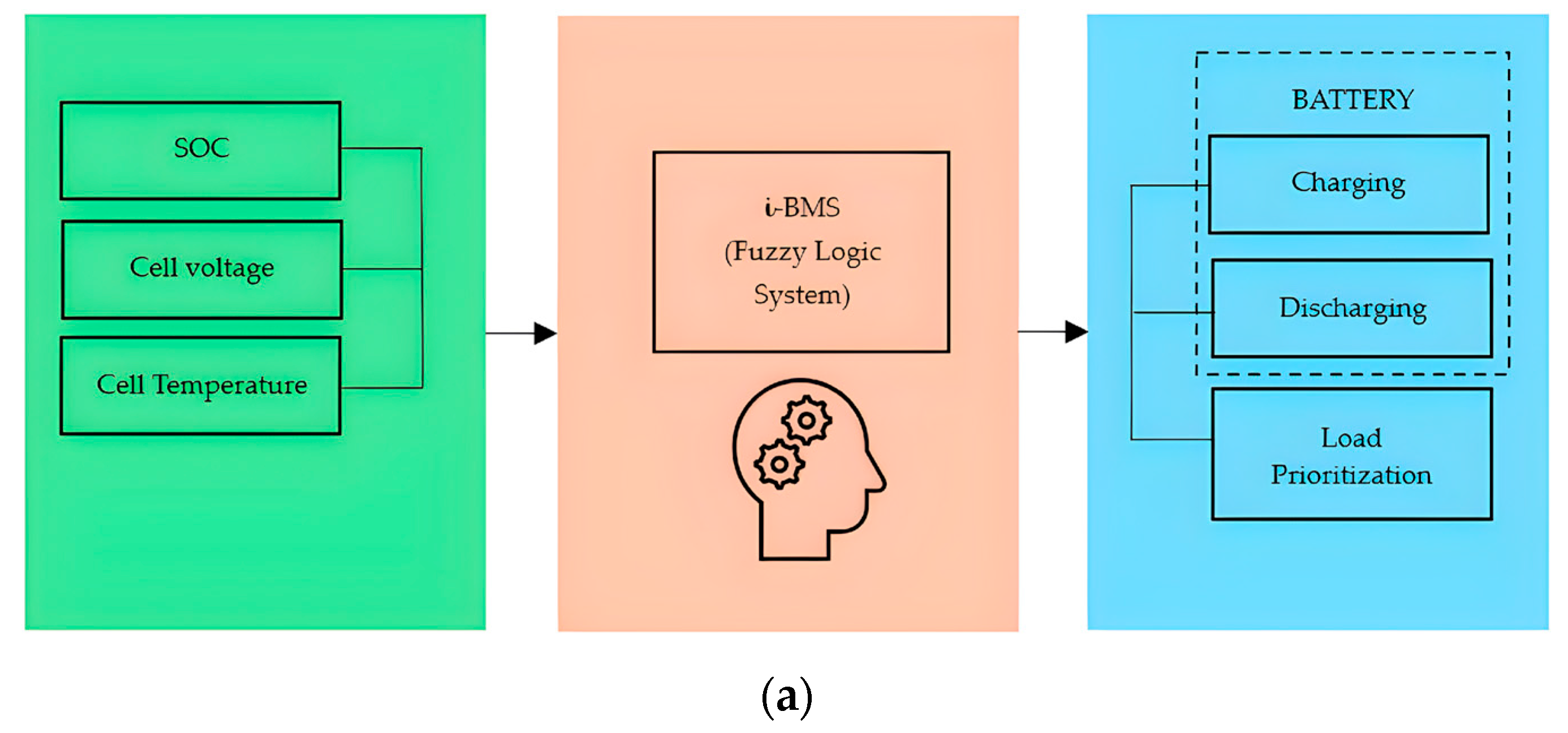
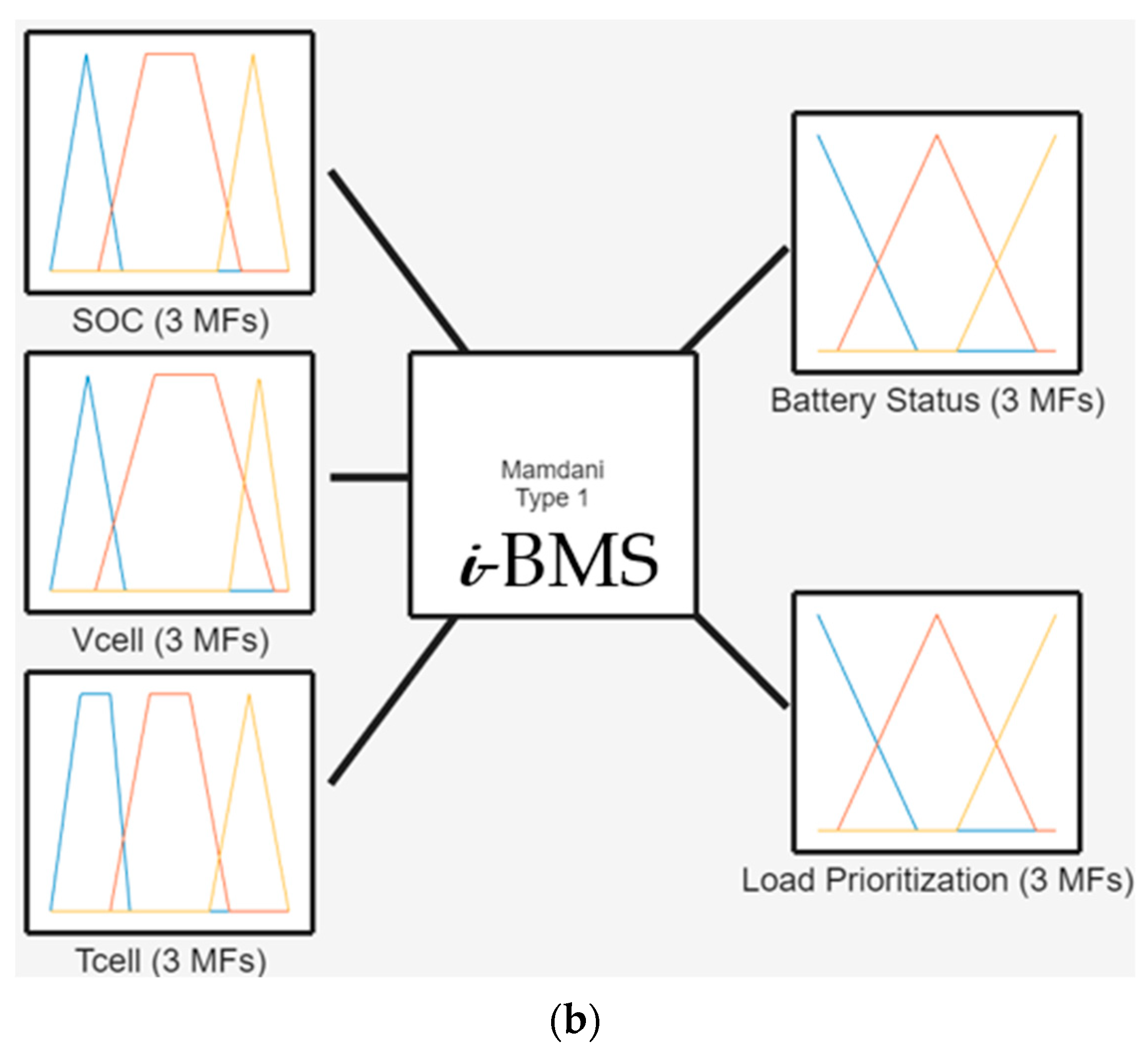
The i-BMS primarily aims to track the battery’s condition and allocate power to the smart farm based on predetermined priority levels. The system automatically transitions to utility grid power if the battery lacks sufficient energy to maintain continuous farm load operations. Figure 6 illustrates the proposed i-BMS that utilizes fuzzy logic to optimize battery operations. The system processes multiple input parameters through an intelligent decision-making model to regulate charging and discharging.
Input parameters include SOC expressed as a percentage, cell voltage (Vcell), and cell temperature (Tcell). Individual battery voltage should be balanced regularly to extend the battery lifespan [45], whereas cell temperature monitoring is essential to avoid thermal runaway [46,47].
The i-BMS controls battery functions based on its fuzzy logic-based decisions, such as charging, discharging, and utility grid connection. Charging will be initiated when SOC is low, and temperature conditions are safe. Discharging will be initiated when load demand is high and SOC is sufficient to supply power to smart farm loads. Lastly, the system can intelligently decide whether to store or distribute energy based on demand and available resources.
Table 3 shows the input linguistic variables and their respective conditions for an i-BMS using fuzzy logic. The SOC is classified into low (0–30%), moderate (20–80%), and high (70–100%). Vcell is one of the indicators of battery health status. This system is subcategorized into low (0–2.5 V), moderate (2.3–3.5 V), and high (3.2–3.6 V). Tcell is categorized as low (0–20 °C), moderate (15–45 °C), and high (40–60 °C). This variable helps the i-BMS regulate energy distribution efficiently based on consumption patterns.
Figure 7 displays the plots of the three fuzzy input variables—SOC, Vcell, and Tcell —categorized as low, moderate, and high using trapezoidal and triangular membership functions.
SOC is divided into three conditions:
  • Low, where batteries are almost depleted;
  • Moderate, where the battery is partially charged;
  • High, indicating a battery close to full capacity.
The Vcell has also three linguistic levels:
  • Low, which corresponds to an undervoltage region where the battery risks deep discharge;
  • Moderate refers to the typical operational range; and
  • High is the near or at maximum charge voltage, signifying a fully charged cell.
Tcell is subcategorized as follows:
  • Low is the level where battery performance may be reduced but not dangerously high;
  • Moderate pertains to the optimal band for regular operation;
  • High temperatures are approaching the upper safety threshold, potentially risking battery degradation.
Table 4 presents the output linguistic values used in the i-BMS, which utilize fuzzy logic to determine appropriate charging or discharging actions based on SOC, Vcell, and Tcell, presented as follows:
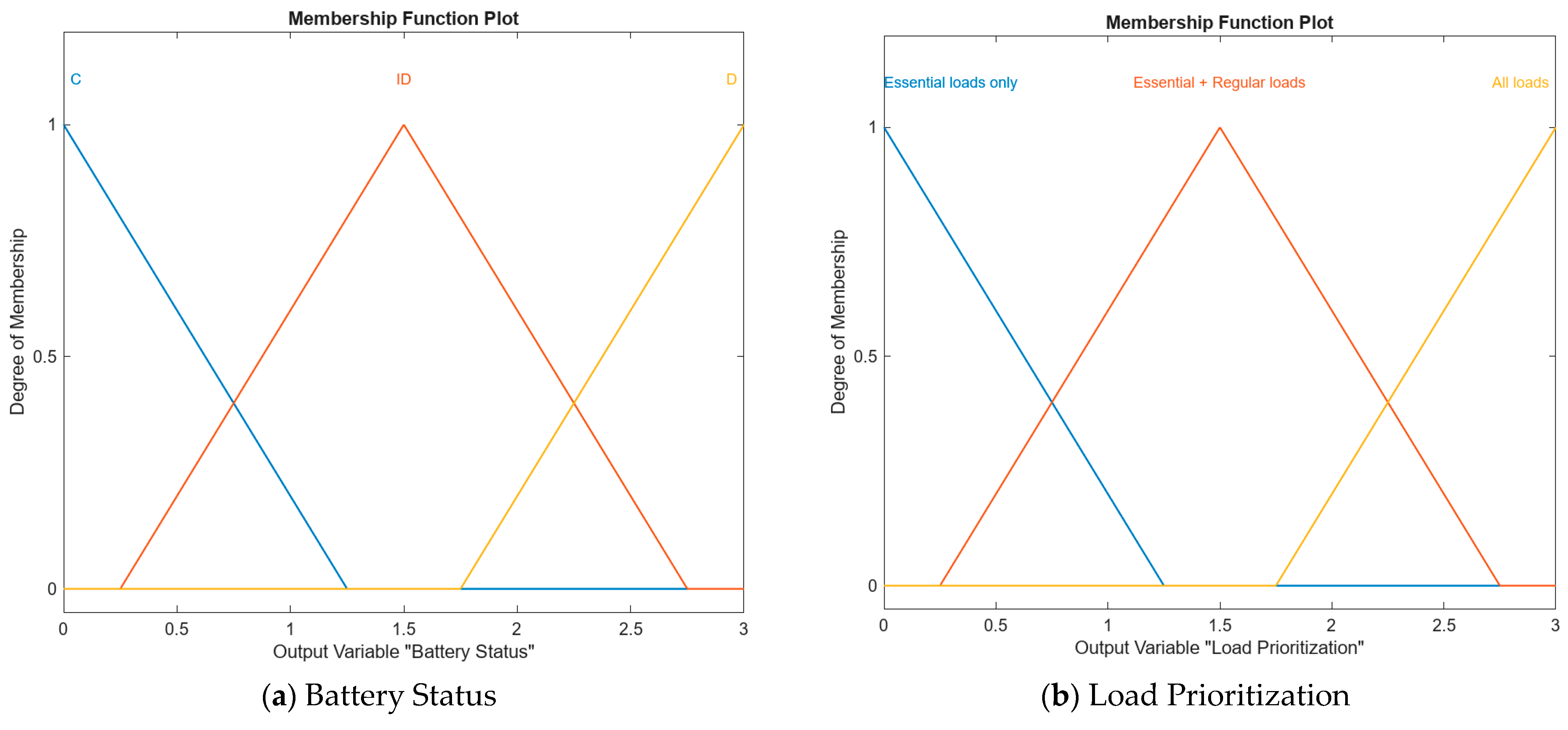
Figure 8 depicts the output-side membership function diagram used by the fuzzy controller to classify the i-BMS charging regime. Three triangular membership functions define the linguistic states: charge (C), idle (ID), and discharge (D). When the cell temperature rises above its safe limit, the controller forces the system into the idle state, disconnects the battery, and draws power from the utility grid to keep the farm running. Once the temperature falls back to the low or moderate bands, the battery is returned online, and the controller selects either charging or discharging according to the real-time SOC, Vcell, and Tcell.
Load allocation decisions are made simultaneously through three priority levels—essential (E), essential + regular (E + R), and all loads—ensuring that limited energy is routed first to critical services. At every control step, the fuzzy inference engine evaluates the three inputs, assigns graded degrees of membership to each of the three charging states, and defuzzifies the result into a single actionable command for the battery system.
Table 5 presents a fuzzy rule-based system for determining the i-BMS’s battery status. The decision is based on three input conditions: SOC, Vcell, and Tcell. These inputs are processed using IF-THEN rules to determine the appropriate battery status and load prioritization. For instance, if SOC,Vcell, and Tcell are low, the system will only direct the battery to the charging state and supply energy to essential loads.

3.6. The i-BMS Electrical Circuit Design

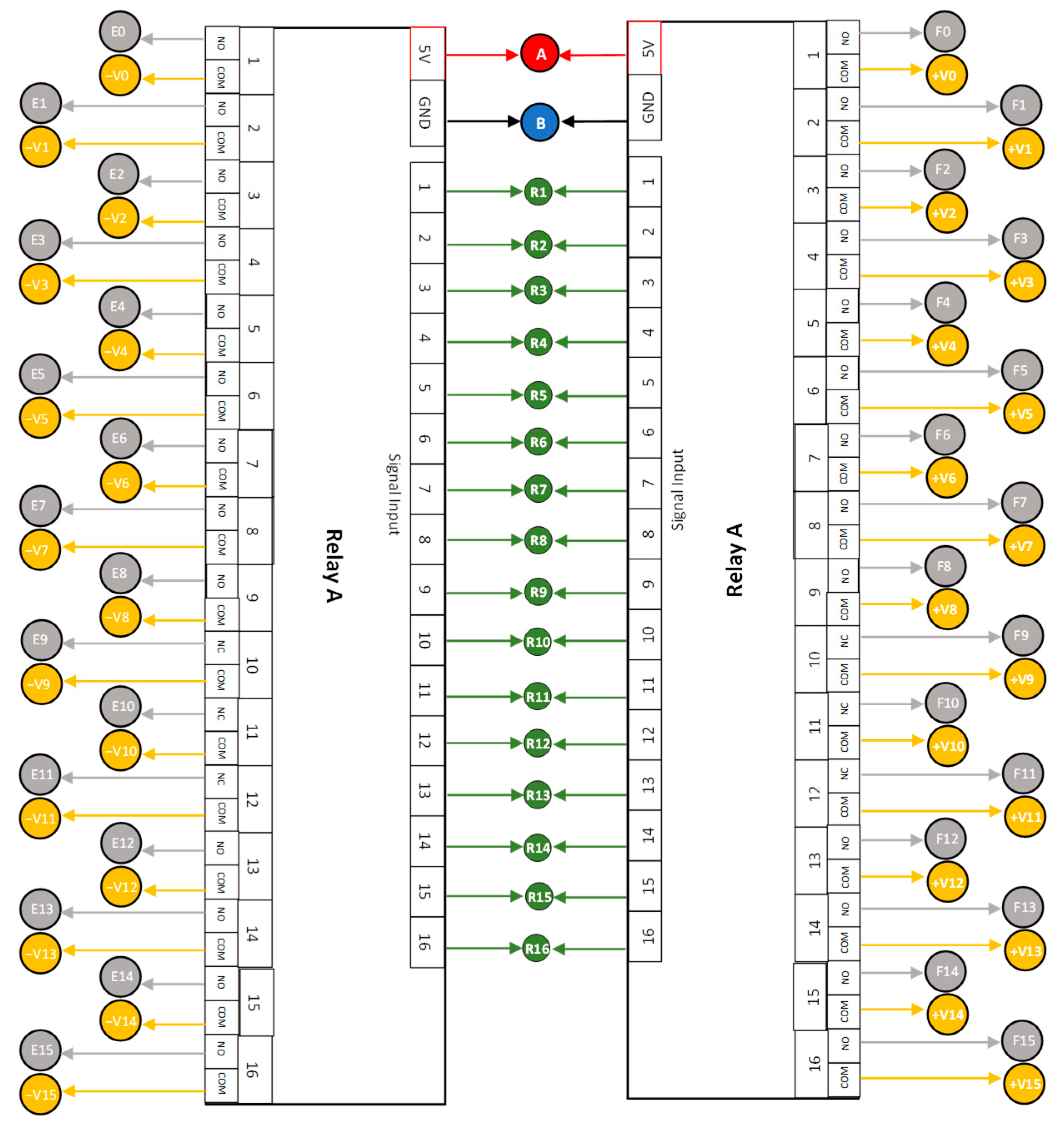
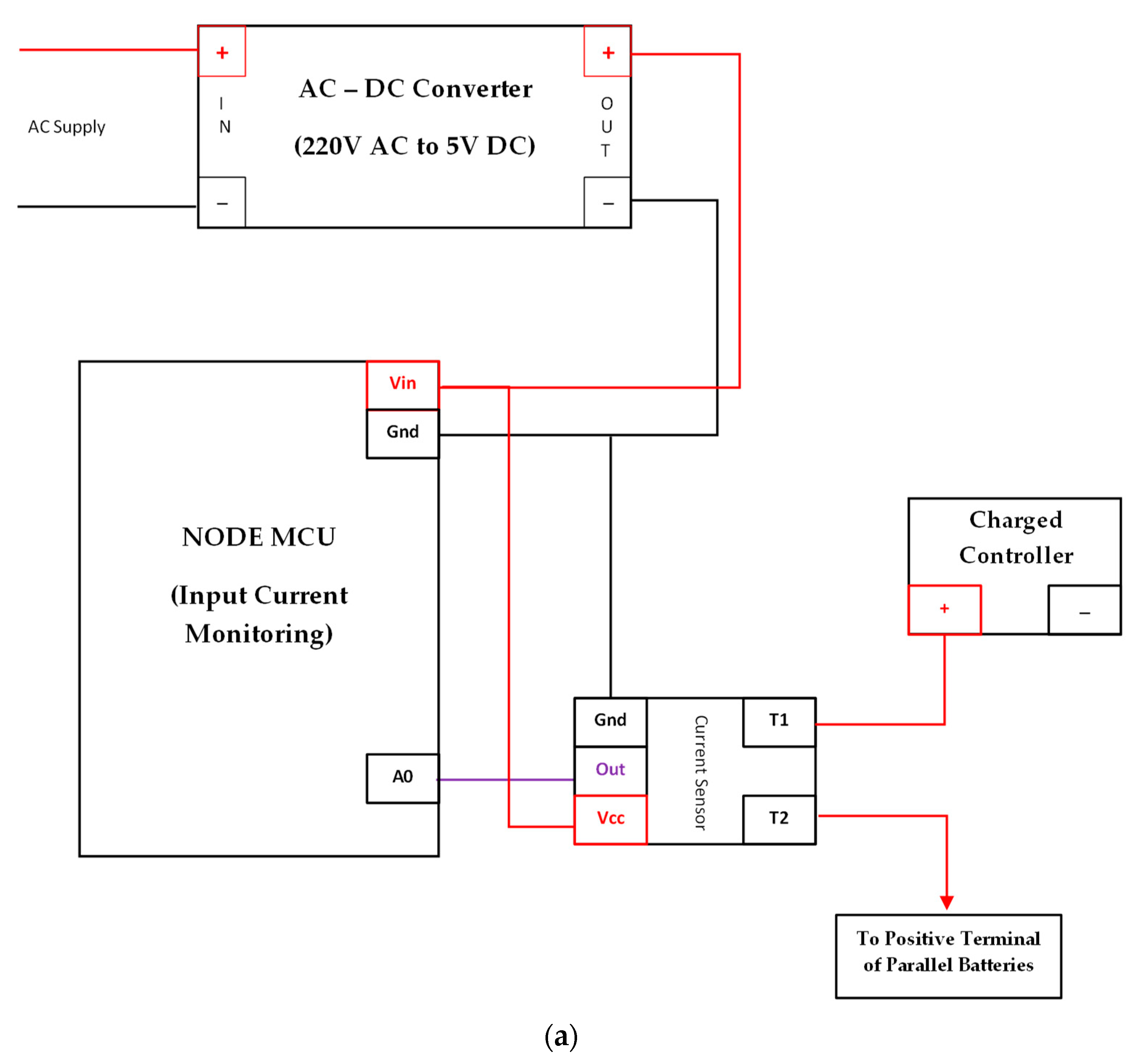
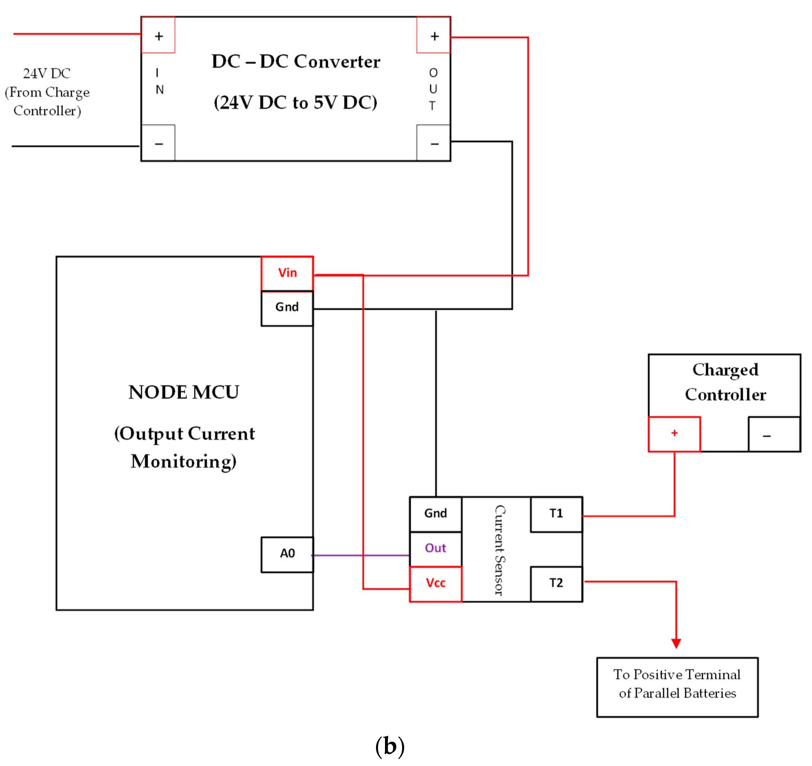
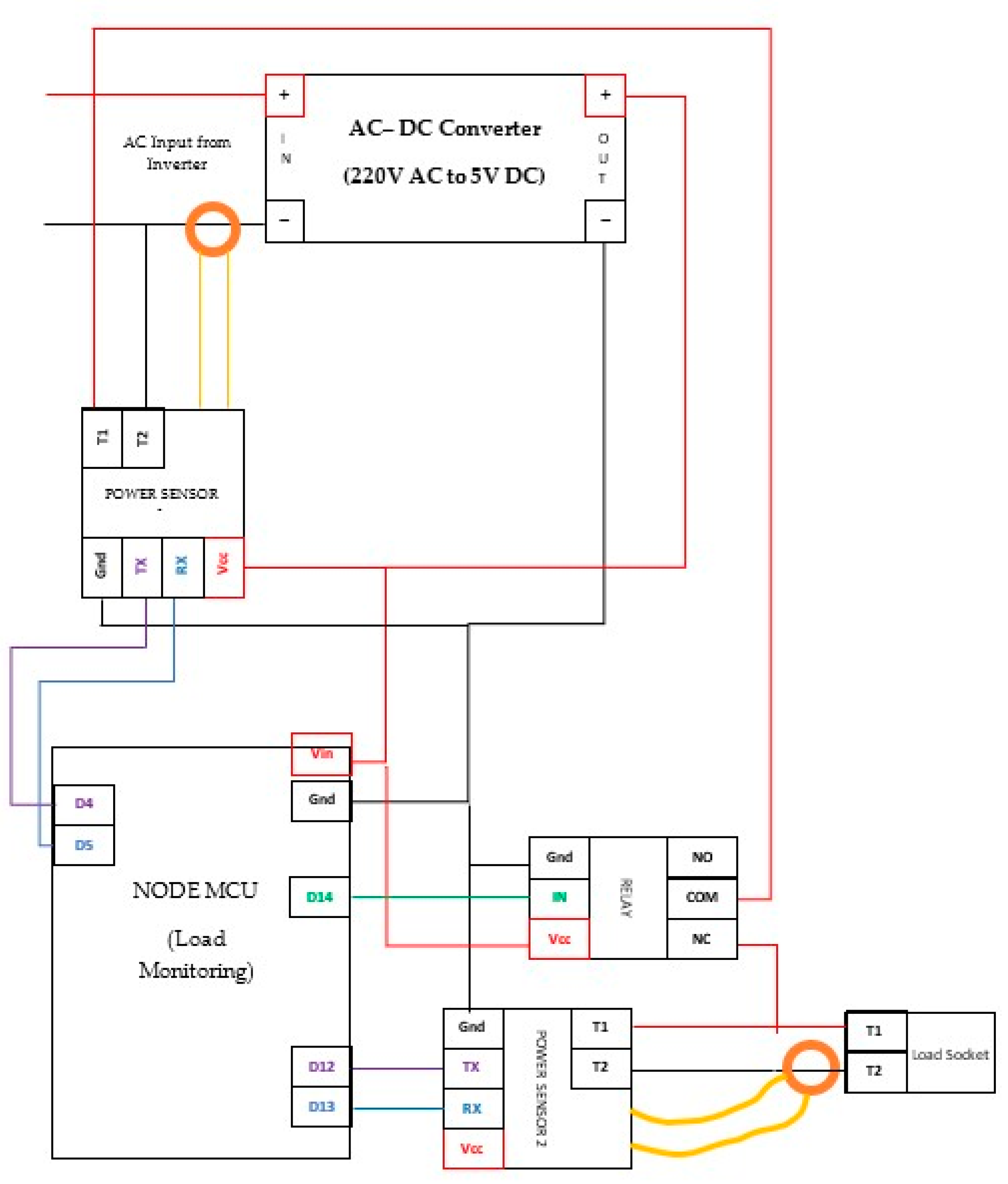
In Figure 9, a 220 VAC-to-5 VDC switch mode supply powers the ESP32 via its Vin pin and feeds two 16-channel analog multiplexers that sit on the same 5VDC supply and ground. Four shared GPIO lines (D14, D26, D25, D32) provide the S3–S0 address bits, while GPIO 17 independently enables or disables each multiplexer so that only one connects to the signal bus at a time. The active multiplexer routes the selected cell tap (C0–C15) to the ESP32′s ADC input on GPIO 34, allowing a single ADC channel to scan up to 16 cell voltages in sequence. Detailed pin assignments for the voltage sensor, including relay connections, voltage and temperature sensor connections, and the current sensor interface, are shown in Figure 10, Figure 11, Figure 12, Figure 13, Figure 14 and Figure 15.

3.7. On-Site Deployment of the Hybrid PV Systems with the i-BMS

Figure 16 illustrates the overall system setup. The experiment platform operates on a hybrid PV system, where the utility grid provides backup energy. The system consists of several key components:
  • Solar charge controller (top right)—Regulates the voltage and current coming from the solar panels to prevent overcharging [48];
  • Automatic transfer switch (middle section)—Controls the transfer of energy sources between solar and utility grid [49];
  • Inverter (center, blue box)—Converts the stored DC power from the batteries into ac [50];
  • Battery bank (Refer to Figure 17)—Stores the energy collected from the solar panels for later use, ensuring power availability even when sunlight is not present [51].
Figure 17 presents the on-site deployment of the i-BMS, showcasing the LMCU, the cell balancing module, the i-BMS control board, and the associated battery banks.
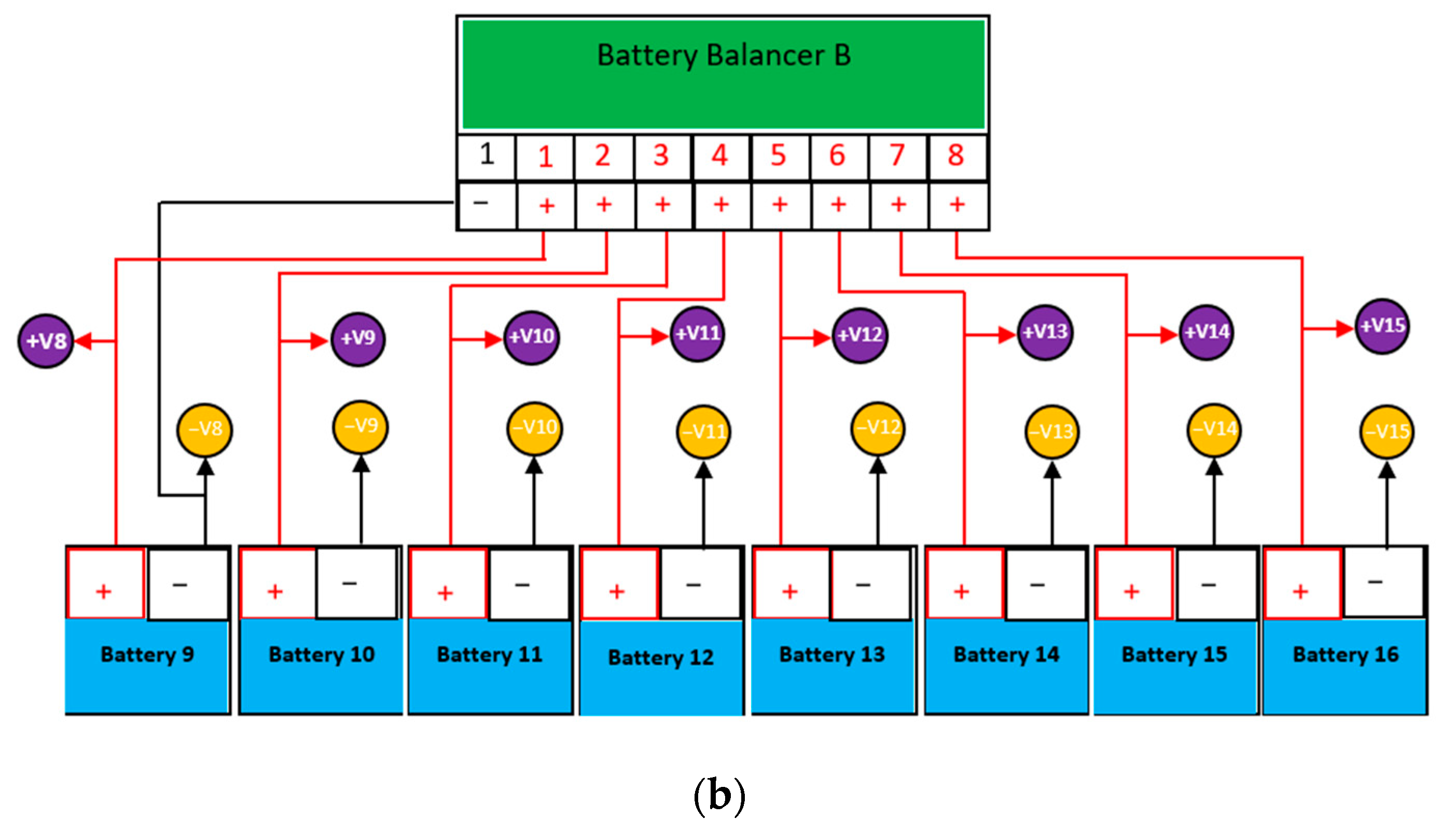
Sixteen pieces of LiFePO4 batteries were deployed on-site in an eight–series–two-parallel (8S-2P) configuration (refer to Figure 18a), with a 24-V, 404 Ah capacity system design. Sixteen voltage and temperature sensors were used to measure and monitor individual cells. Two current sensors were deployed at the load input and output terminals. The cell balancing module monitors and regulates the voltage of each cell to ensure the batteries remain balanced [52]. This i-BMS uses an active balancing circuit in Figure 18b.
Table 6 presents the summary of the battery specification used in this study.
The LMCU (refer to Figure 18c) prioritizes whether the farm’s load demands are essential, regular, or non-essential. The system responds based on the priority level. It also validates the state of the batteries before supplying the energy demand.
The load prioritization categories are as follows:
  • Essential loads—These loads are mission-critical and require uninterrupted power supply due to their operational requirements. They include life support systems for aquaculture tanks and security systems such as CCTV. They are last to shed, first to restore.
  • Regular loads—These are operationally necessary loads, and short outages are tolerable, leaving no severe damage or impact on system operations. Loads include irrigation pumps, data logging servers, and IoT gateways.
  • Non-essential loads—These loads are usually not vital to smart farm operations and thus pertain to convenience or discretionary loads. They may operate only when surplus energy exists. This may include electric vehicles, decorative lighting, or household loads.
Furthermore, Table 7 summarizes the sensors and control modules utilized in this study, along with their operating range, resolution, and accuracy.

3.8. Real-Time i-BMS Monitoring System

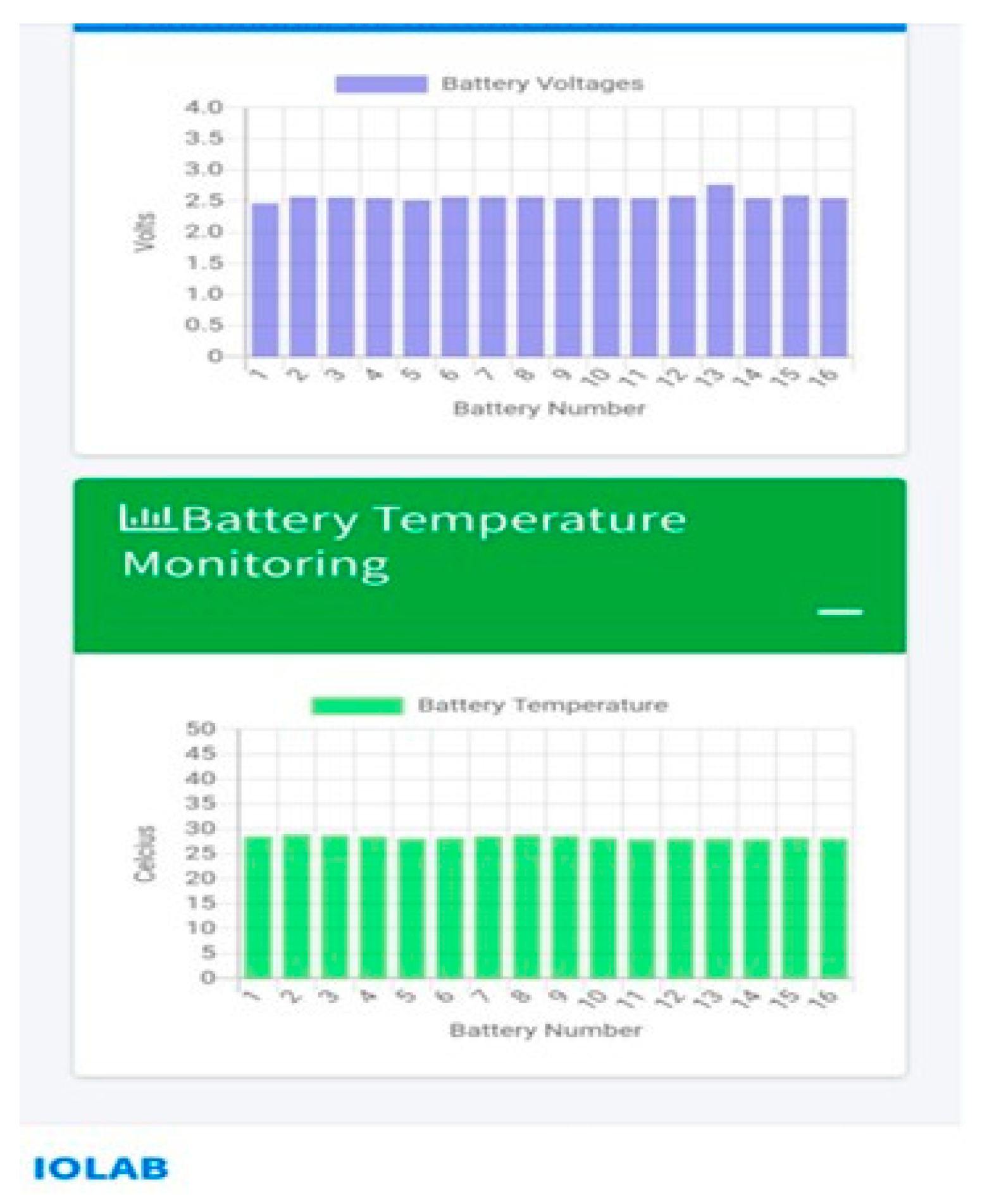
Figure 19 shows the mobile dashboard of the t-BMS, which is used for monitoring the battery status. In contrast, Figure 20, when viewed on a laptop or desktop, displays a navigation panel on the left side that lists various monitoring and management functions, including battery monitoring, load monitoring, and others. Within the main window, there are two bar charts: (1) battery voltage monitoring, which displays the 16 individual voltages in bars, and (2) battery temperature monitoring, a bar chart that shows temperature readings for the same set of batteries.
This dashboard provides a comprehensive view of key battery parameters across multiple cells, enabling a quick assessment of the health and status of each battery in the system.

3.9. i-BMS Data Transmission

The i-BMS consists of three Wi-Fi nodes: an ESP32 for multiplexed cell voltage and DS18B20 temperature measurements, an ESP8266 with an ACS712 Hall sensor for pack current readings, and a second ESP8266 equipped with dual PZEM-004T meters, with a relay for AC-side monitoring and load control. Each board communicates directly with an SQL database over plain HTTP. Sensor data are sent as HTTP GET requests to designated endpoints, and control commands are retrieved by polling another URL. When a load is toggled in the web app, the change is written to the SQL table. On the next polling cycle, the ESP8266 reads the updated flag and flips its GPIO relay accordingly. This direct HTTP → SQL → HTTP loop—is implemented entirely on the free hosting account and delivers real-time telemetry and remote load control.

4. Fuzzy Logic-Based i-BMS Learning Structure

MATLAB was the primary platform for designing, simulating, and validating i-BMS configurations. A classical Mamdani-type fuzzy inference system (FIS) was implemented, following the standard workflow of fuzzification → rule evaluation → aggregation → defuzzification. As illustrated in Figure 21 (Property Editor snapshot), the controller applies the minimum (min) operator for both the AND condition and rule implication, the maximum (max) operator for the OR condition and rule aggregation, and the centroid technique for defuzzification. The FIS accepts three input variables and produces two distinct outputs, yielding a complete rule base of 27 (33) rules that comprehensively cover all possible operating states of the battery system.
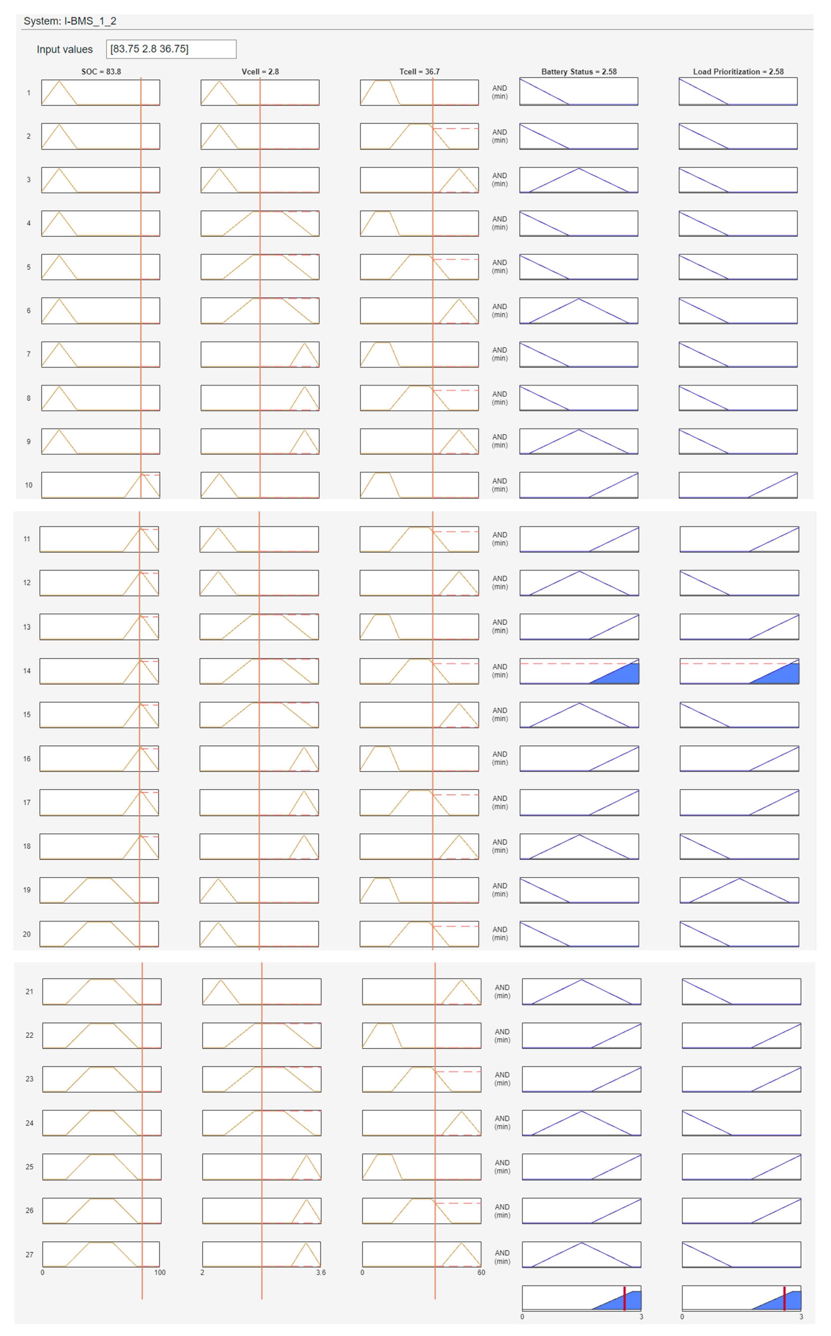
Figure 22 illustrates that the i-BMS controller with SOC = 83.8%, Vcell = 2.8 V, and Tcell = 36.7 °C produces fuzzy outputs of battery status = 2.58 and load prioritization = 2.58. On the scale defined for this Mamdani FIS, a value near three corresponds to the Discharge–-High state and the All-Loads category. Hence, the i-BMS interprets these inputs as follows:
  • The battery is healthy within its safe operating limits;
  • Ample stored energy is available to power the entire farm—essential, regular, and non-essential loads—without drawing from the grid.
Thus, the controller authorizes full discharge to satisfy total demand while continuously monitoring temperature and cell voltage to prevent unsafe conditions.
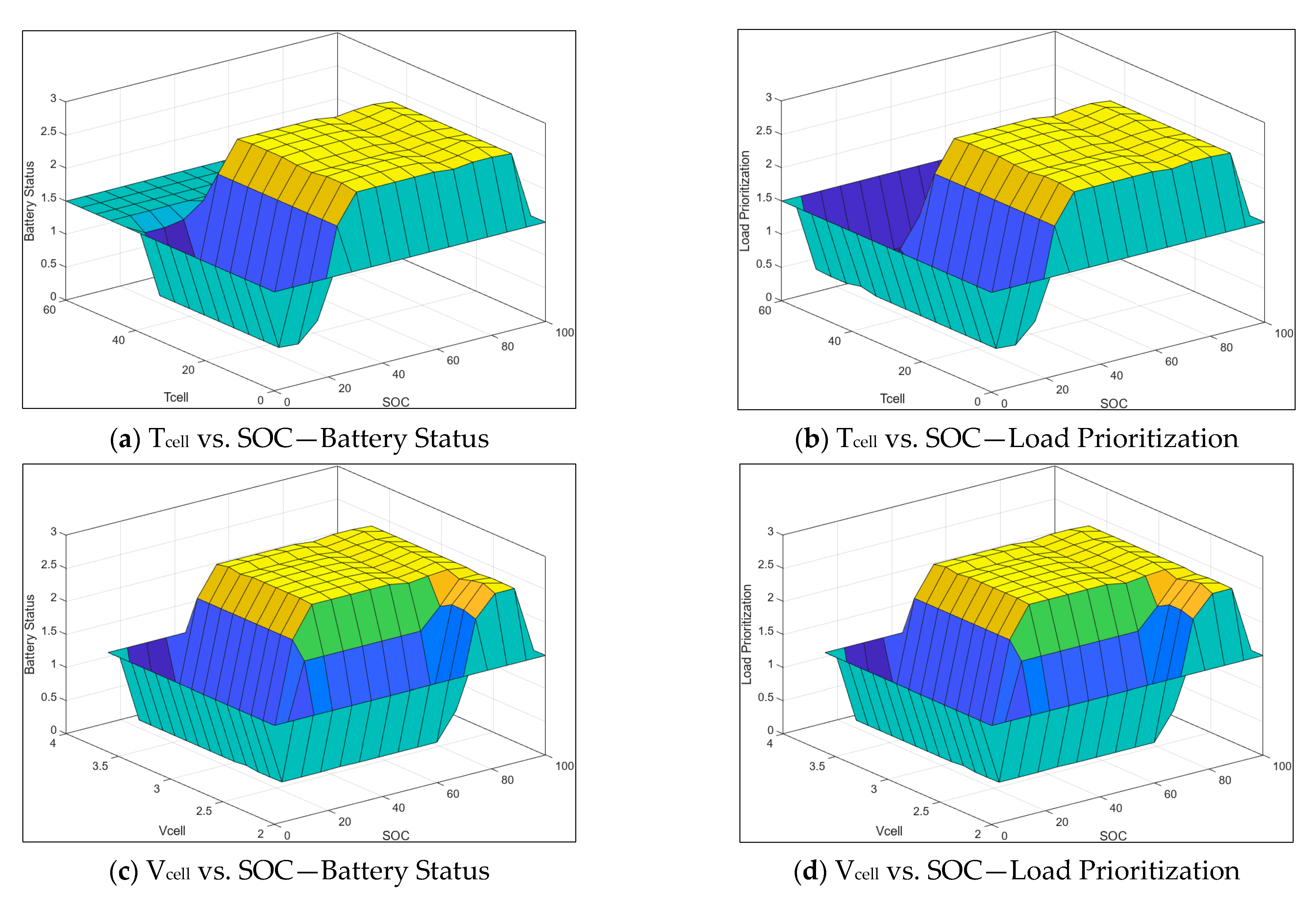
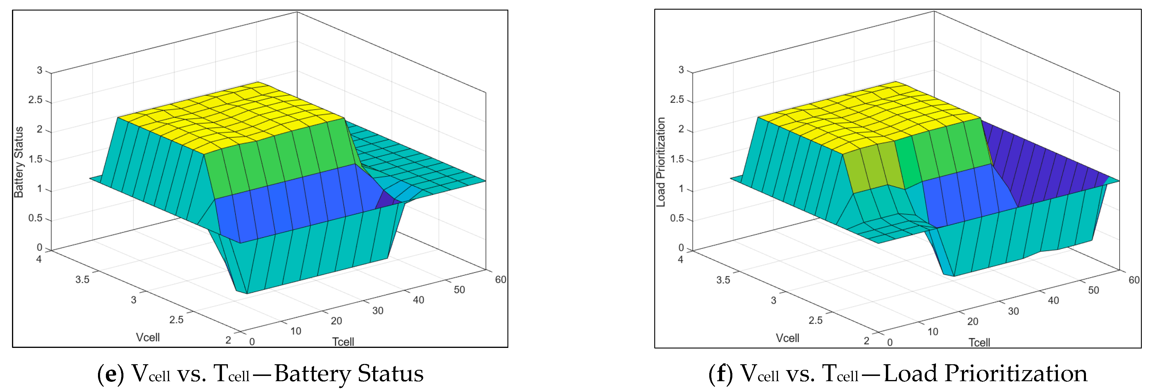
Figure 23 illustrates the control surface maps produced by the Mamdani Type-1 i-BMS. For each input pair plotted on the X- and Y-axes (SOC × Tcell, SOC × Vcell, and Tcell × Vcell), the Z-axis shows the following:
  • Battery operating mode—charge, idle, or discharge—in Figure 23a,c,e;
  • Load prioritization level—essential only, essential + regular, or all loads—in Figure 23b,d,f.
These surfaces visualize how the controller simultaneously decides the pack’s dispatch state and the farm’s load mix across every combination of state-of-charge, cell voltage, and temperature.
In Figure 23a, the blue–turquoise trough at z = 0–1 corresponds to a low-SOC region (≤25%). Here, the fuzzy controller explicitly issues a charge command—overriding cell temperature considerations—to restore the battery’s reserve. Figure 23b shows a similar trough: while the pack is being replenished, the system restricts power delivery to essential loads only, shedding all non-critical demand until the SOC rises above the recovery threshold. A moderate SOC, around 25–60%, and safe Tcell (<≈45 °C) sloping face, colored blue, where z rises toward 2, is when the pack is allowed to discharge at a moderate rate; the higher the SOC, the stronger the discharge command. Also, the same corresponding face is where the system gradually enables regular loads in addition to the essential ones. A high SOC of greater than 60% and safe Tcell, the broad yellow plateau approximately z = 2.3–2.4, occurs when the controller authorizes full-rate discharge. A similar graph (Figure 23b) also shows a yellow plateau, enabling all three load categories. Lastly, when the Tcell surpasses 45 °C, both control surfaces flatten into a distinctive teal shelf at z = 1.5. This plateau activates the FIS’s temperature override safeguard, idle state, and essential loads only. No further energy exchange resumes until the temperature falls back into the safe operating range.
Figure 23c–f confirms that the controller behaves consistently across the remaining input planes:
  • Battery status surfaces (Figure 23c: Vcell × SOC, Figure 23e: Vcell × Tcell) progress smoothly from charge through idle to discharge as the operating point moves from low-energy/low-voltage zones to high-energy thermally safe regions, provided the point lies inside the permissible envelope;
  • Load prioritization companions (Figure 23d,f) mirror this progression, sequentially enabling essential, then regular, and finally non-essential loads in lock-step with the battery’s dispatch state.
Taken together, these maps demonstrate that i-BMS applies a uniform rule set to every combination of inputs, ensuring predictable, coordinated decisions throughout the safe operating area.

5. Results and Discussion

i-BMS and traditional BMS were implemented in a real physical system. Its operation is remotely monitored in real time via a website.
Figure 24a plots the voltage of each cell at successive time stamps (colored markers) with no balancing circuitry in place. As the test progressed, the pack visibly drifted: the highest charged cells climbed to about 3.13–3.55 V, whereas the weakest sagged to roughly 2.68–2.90 V. These disparities persisted, showing that passive equalization alone could not bring the cells to a standard level. In sharp contrast, Figure 24b captures the same pack after enabling the i-BMS balancing algorithm. The out-of-tolerance cells were pulled back into line, and all voltages rapidly converged within a tight window, demonstrating effective active balancing across the stack.
As summarized in Table 8, the i-BMS uses the voltage readings from the 16 voltage sensors to show the minimum voltage, maximum voltage, and standard deviation for each battery. This experiment used around 4700 datasets.
The following are the findings about the performance of the cell balancing circuit:
  • There is a sufficient dataset for the experiment.
  • The mean for all the batteries is within the safe region. However, the minimum cell voltage for batteries numbered 7, 9, and 14 is below the lower cut-off voltage.
  • The maximum voltage for batteries numbered 1–4, 7,9, and 13–14 goes beyond the upper threshold voltage.
  • The pack is not well balanced: the difference between the highest and lowest mean cell voltages is ~0.35 V.
  • Several cells have experienced unsafe voltage extremes (>3.65 V or <2.5 V), which can shorten life or pose safety risks.
  • Cells 9, 12, 13, and 14 stand out for their high variability; Cell 14 is the weakest, and Cell 13 is the most overcharged.
  • To restore uniformity and pack longevity, a balancing routine, stricter charge/discharge cut-offs, or replacing the outlier cells is advisable.
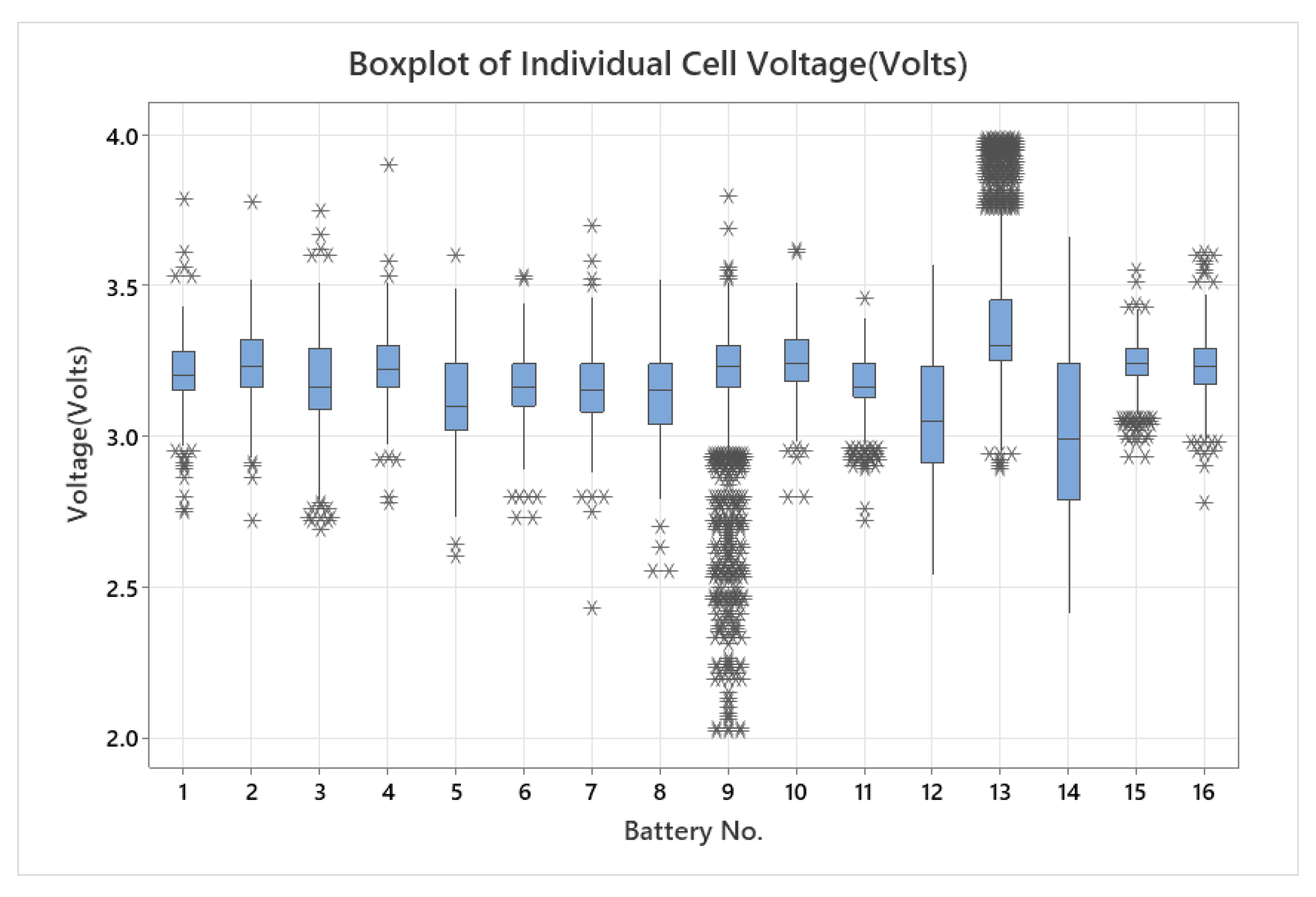
These findings are further confirmed by the boxplot shown in Figure 25, where there are several outliers(*) for almost all the batteries.
Table 9 shows that the cells remained within the safe thermal band: the overall mean operating temperature was 27.10 °C, with a minimum of 18.94 °C and a maximum of 31.31 °C, which is inside the −20 to 60 °C range recommended for LiFePO4 batteries. The boxplot in Figure 26 reinforces this finding, with its tight interquartile range and absence of outliers across all cells confirming consistently stable temperature behavior during the entire test.
Table 10 shows power is measured at around 53 to 54 watts for the regular load category. The essential and non-essential load categories draw the same amount of power at a particular time. The farm’s energy supply requirement was delivered based on its priority level. The three load categories show consistency and steady supply.
Based on Figure 27, essential loads remained relatively stable, indicating consistent demand. Regular loads showed a slight dip but stay close to the 53–54 W range over the monitored interval. Lastly, non-essential loads trended slightly downward in power usage, yet remained near the same overall level.
The percentage chart reveals that essential loads comprised the most significant portion of total consumption, followed by regular loads at roughly a quarter and non-essential loads at 18%. Overall, all three load categories displayed minimal fluctuation in power draw, with essential loads dominating the total share.
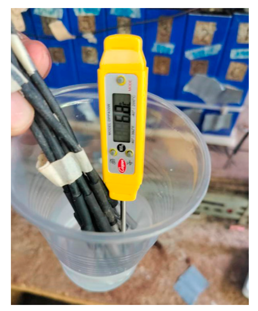
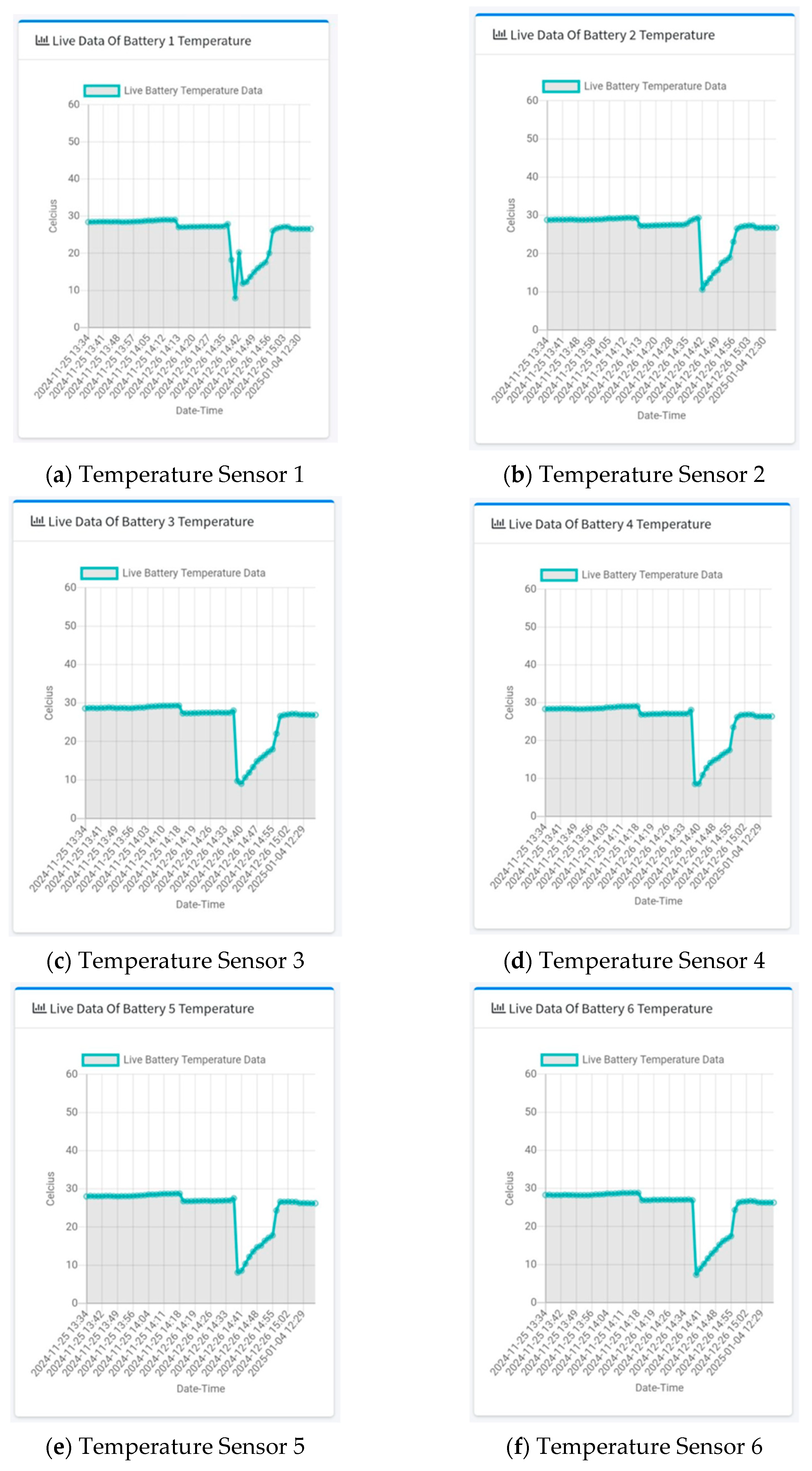
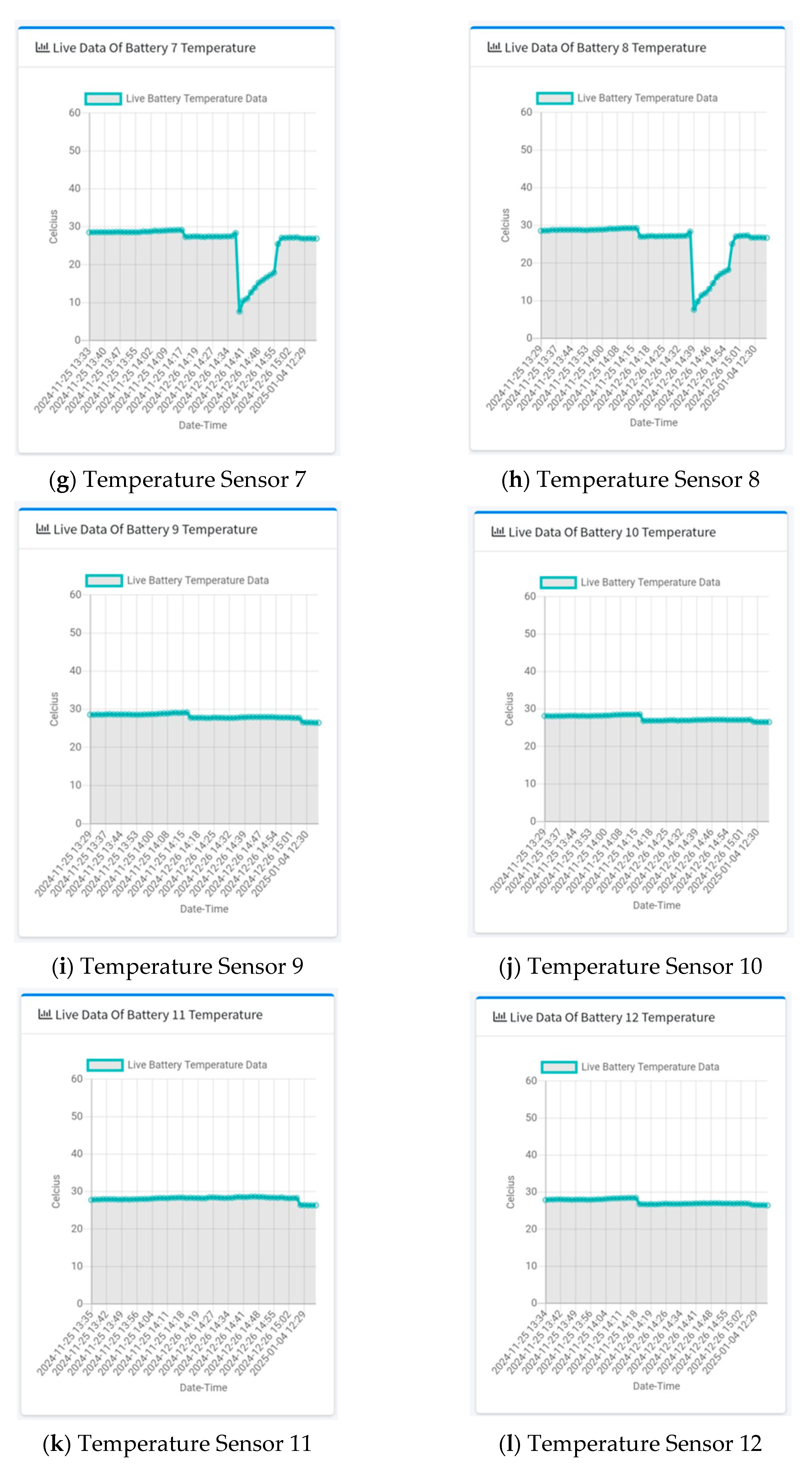
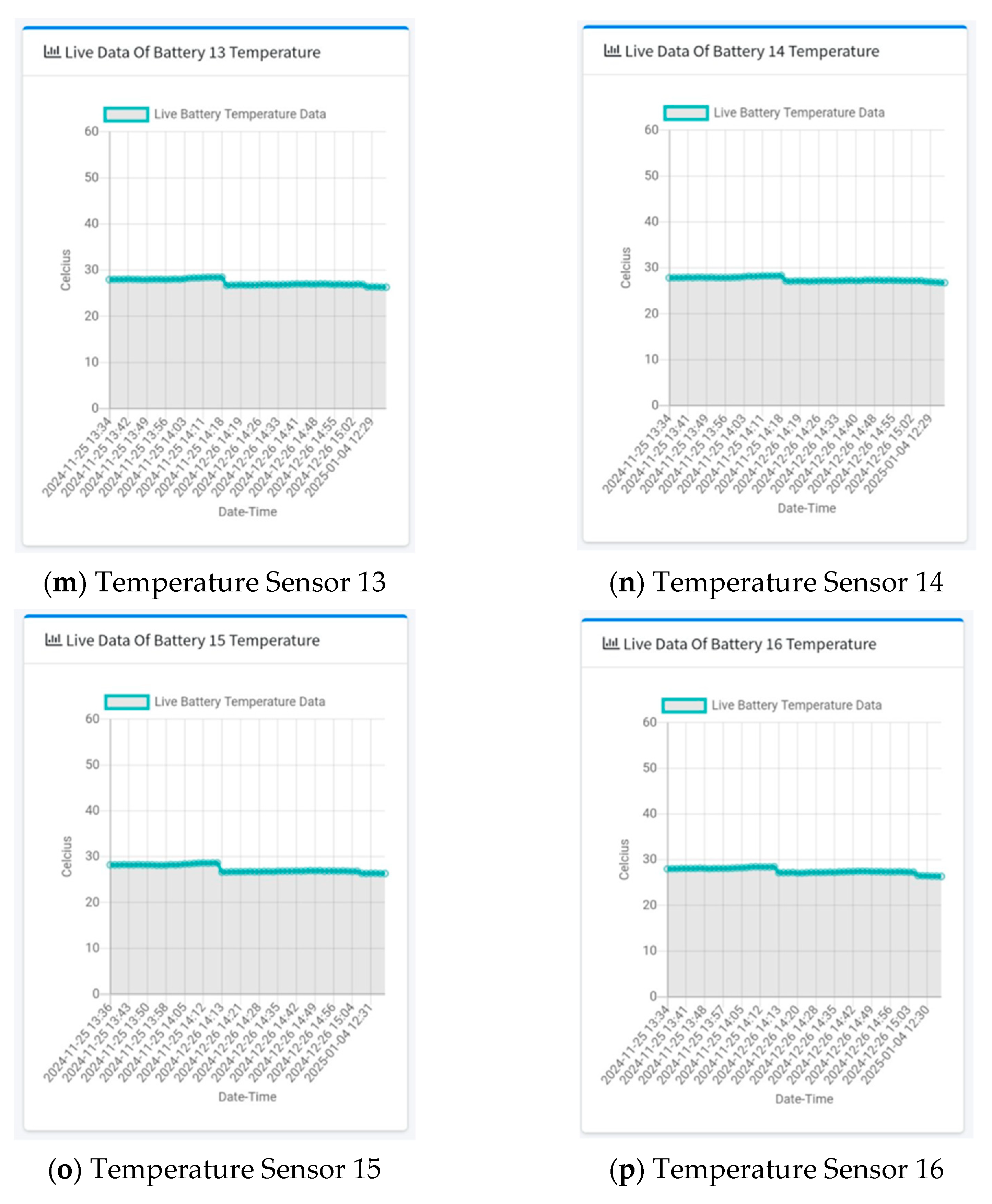
Sensors 1 to 8 were dipped into cold water with a food thermometer attached, as shown in Figure 28, to verify that the temperature sensors were working correctly.
Figure 29 compares the reference food thermometer reading with the i-BMS sensor data. At around 14:36, Temperature Sensors 1–8 were deliberately immersed in cold water, producing a sharp, synchronous drop that the i-BMS captured in real time. Temperature Sensors 9–16, which remained adhered to the battery surface, recorded virtually unchanged values over the same interval. The close correspondence between the reference instrument and Sensors 1–8 during the transient and the stability of Sensors 9–16 demonstrates the i-BMS module’s accuracy and consistency throughout the test.
In this research, the developed prototype accomplished the following:
  • The system successfully balanced the voltage across the batteries, ensuring uniform energy distribution and reducing the risk of overcharge or undercharge conditions.
  • This monitoring system remotely tracked battery voltage, temperature, and power distribution. By prioritizing power distribution based on predefined levels, the system maintained optimal performance under varying operational loads.
  • This intelligent control system is effective and reliable in decision-making, handling uncertainties in the sensor data, and adapting to fluctuating load operating conditions without compromising performance.
Developing this i-BMS presented several challenges, which are as follows:
  • Voltage sensors experienced frequent malfunctions, leading to replacement.
  • Loose circuit connections resulted in repetitive system failures.
  • The automatic transfer switch malfunctioned two times, resulting in replacement.
  • Battery terminals began to show signs of rust.
  • Batteries also experienced imbalances, most of the time.
  • Several batteries exhibited bloating.
  • The prepaid Wi-Fi limits the number of devices that can be connected simultaneously, hindering the whole system operation at the farm.

6. Conclusions and Recommendations

In this study, we successfully deployed the i-BMS with 16 temperature sensors, 16 voltage sensors, and two current sensors. The i-BMS balanced the voltage across the batteries to ensure uniform energy distribution, monitor battery parameters, and execute power distribution based on priority levels.
The i-BMS efficiently and effectively delivers the required energy demand of the smart farm through a fuzzy logic system for its management and control. The website lets users view the farm’s battery status, available energy, and load demands in real time.
Even though the prototype of the i-BMS exhibited significant improvements over traditional battery management approaches, there are still several areas where the system can be enhanced to optimize its performance, efficiency, and reliability fully. Future researchers may consider incorporating advanced machine learning models to improve real-time analysis to predict battery degradation. Another area of study that can be explored is developing a more robust fault detection algorithm that monitors battery health and anticipates potential safety issues.

Author Contributions

Conceptualization, methodology, software, validation, formal analysis, investigation, resources, data curation, writing—original draft preparation, J.-A.V.M.; validation, A.A.B.; validation, A.B.C.; validation, E.S.; validation, R.R.P.V.; validation, R.N.; and project administration, supervision, validation, writing—review and editing, E.P.D. All authors have read and agreed to the published version of the manuscript.

Funding

This research was funded by the Department of Science and Technology-Engineering Research and Development for Technology (DOST-ERDT) and De La Salle University.

Institutional Review Board Statement

Not applicable.

Informed Consent Statement

Not applicable.

Data Availability Statement

Data are available upon request.

Acknowledgments

The research team gratefully acknowledges the invaluable support provided by DOST-ERDT and De La Salle University.

Conflicts of Interest

The authors declare no conflicts of interest.

Abbreviations

The following abbreviations are used in this manuscript:
BMSBattery Management System
IBMSIntelligent Battery Management System
PVPhotovoltaic
SFSmart Farming

References

  1. Solangi, Y.A.; Magazzino, C. Evaluating financial implications of renewable energy for climate action and sustainable development goals. Renew. Sustain. Energy Rev. 2025, 212, 115390. [Google Scholar] [CrossRef]
  2. Ganguly, A.; Biswas, P.K.; Sain, C.; Ustun, T.S. Modern DC–DC Power Converter Topologies and Hybrid Control Strategies for Maximum Power Output in Sustainable Nanogrids and Picogrids—A Comprehensive Survey. Technologies 2023, 11, 102. [Google Scholar] [CrossRef]
  3. Dehghani-Sanij, A.R.; Tharumalingam, E.; Dusseault, M.B.; Fraser, R. Study of energy storage systems and environmental challenges of batteries. Renew. Sustain. Energy Rev. 2019, 104, 192–208. [Google Scholar] [CrossRef]
  4. Rasentharah, K.K.; Hassan, M.K.; Hoque, M.A.; Hajjo, A. Lithium Iron Phosphate (LiFePo4) Batteries Health Prognosis via Plateau Identification during High-Rate Charging and Discharging. In Proceedings of the 2023 IEEE 13th International Conference on System Engineering and Technology (ICSET), Shah Alam, Malaysia, 2 October 2023; pp. 182–187. [Google Scholar] [CrossRef]
  5. Kumar, J.; Neiber, R.R.; Park, J.; Soomro, R.A.; Greene, G.W.; Mazari, S.A.; Seo, H.Y.; Lee, J.H.; Shon, M.; Chang, D.W.; et al. Recent progress in sustainable recycling of LiFePO4-type lithium-ion batteries: Strategies for highly selective lithium recovery. Chem. Eng. J. 2022, 431, 133993. [Google Scholar] [CrossRef]
  6. Lu, Y. Study on the performance of lithium iron phosphate battery based on its application in transportation field. J. Phys. Conf. Ser. 2024, 2798, 012019. [Google Scholar] [CrossRef]
  7. Murlidharan, S.; Ravulakole, V.; Karnati, J.; Malik, H. Battery Management System: Threat Modeling, Vulnerability Analysis, and Cybersecurity Strategy. IEEE Access 2025, 13, 37198–37220. [Google Scholar] [CrossRef]
  8. Magsumbol, J.A.V.; Rosales, M.A.; Palconit, M.G.; Concepcion, R.S., II; Bandala, A.A.; Vicerra, R.R.P.; Sybingco, E.; Culaba, A.; Dadios, E.P. A Review of Smart Battery Management Systems for LiFePO4: Key Issues and Estimation Techniques for Microgrids. J. Adv. Comput. Intell. Intell. Inform. 2022, 26, 824–833. [Google Scholar] [CrossRef]
  9. Dai, H.; Jiang, B.; Hu, X.; Lin, X.; Wei, X.; Pecht, M. Advanced battery management strategies for a sustainable energy future: Multilayer design concepts and research trends. Renew. Sustain. Energy Rev. 2021, 138, 110480. [Google Scholar] [CrossRef]
  10. Krishna, G.; Singh, R.; Gehlot, A.; Akram, S.V.; Priyadarshi, N.; Twala, B. Digital Technology Implementation in Battery-Management Systems for Sustainable Energy Storage: Review, Challenges, and Recommendations. Electronics 2022, 11, 2695. [Google Scholar] [CrossRef]
  11. Zhou, L.; Lai, X.; Li, B.; Yao, Y.; Yuan, M.; Weng, J.; Zheng, Y. State Estimation Models of Lithium-Ion Batteries for Battery Management System: Status, Challenges, and Future Trends. Batteries 2023, 9, 131. [Google Scholar] [CrossRef]
  12. Vennam, G.; Sahoo, A.; Ahmed, S. A survey on lithium-ion battery internal and external degradation modeling and state of health estimation. J. Energy Storage 2022, 52, 104720. [Google Scholar] [CrossRef]
  13. Masakure, A.; Gill, A.; Singh, M. The Impact of Battery Charging and Discharging Current Limits on EV Battery Degradation and Safety. In Proceedings of the 2023 3rd Asian Conference on Innovation in Technology (ASIANCON), Ravet IN, India, 25–27 August 2023; pp. 1–5. [Google Scholar] [CrossRef]
  14. Vinodkumar; Singha, N.S. Battery Management System Health Monitoring Using Artificial Intelligence. In Proceedings of the 2023 International Conference on Sustainable Emerging Innovations in Engineering and Technology (ICSEIET), Ghaziabad, India, 14–15 September 2023; pp. 31–35. [Google Scholar] [CrossRef]
  15. Wang, H.; Tsang, K.F.; Wu, C.K.; Wei, Y.; Liu, Y.; Lai, C.S. IEEE P2668 Compatible Evaluation Strategy for Smart Battery Management Systems. Sensors 2022, 22, 6057. [Google Scholar] [CrossRef] [PubMed]
  16. E. Committee, I. Power, E. Society. IEEE Recommended Practice for Battery Management Systems in Stationary Energy Storage Applications. 2024. Available online: https://ieeexplore.ieee.org/browse/standards/collection/ieee (accessed on 13 May 2025).
  17. Plett, G.L. Battery Management System: Equivalent Circuit Methods; Artech House: Norwood, MA, USA, 2016; Volume 2. [Google Scholar]
  18. Hannan, M.A.; Lipu, M.S.H.; Hussain, A.; Mohamed, A. A review of lithium-ion battery state of charge estimation and management system in electric vehicle applications: Challenges and recommendations. Renew. Sustain. Energy Rev. 2017, 78, 834–854. [Google Scholar] [CrossRef]
  19. Lee, H.; Park, J.; Kim, J. Incremental capacity curve peak points-based regression analysis for the state-of-health prediction of a retired LiNiCoAlO2 series/parallel configured battery pack. Electronics 2019, 8, 1118. [Google Scholar] [CrossRef]
  20. Song, Z.; Yang, X.G.; Yang, N.; Delgado, F.P.; Hofmann, H.; Sun, J. A study of cell-to-cell variation of capacity in parallel-connected lithium-ion battery cells. ETransportation 2021, 7, 100091. [Google Scholar] [CrossRef]
  21. Lelie, M.; Braun, T.; Knips, M.; Nordmann, H.; Ringbeck, F.; Zappen, H.; Sauer, D.U. Battery management system hardware concepts: An overview. Appl. Sci. 2018, 8, 534. [Google Scholar] [CrossRef]
  22. Hu, X.; Feng, F.; Liu, K.; Zhang, L.; Xie, J.; Liu, B. State estimation for advanced battery management: Key challenges and future trends. Renew. Sustain. Energy Rev. 2019, 114, 109334. [Google Scholar] [CrossRef]
  23. Kumar, R.; Das, K. Lithium battery prognostics and health management for electric vehicle application—A perspective review. Sustain. Energy Technol. Assess. 2024, 65, 103766. [Google Scholar] [CrossRef]
  24. Pastor-Fernández, C.; Widanage, W.D.; Chouchelamane, G.H.; Marco, J. A SoH diagnosis and prognosis method to identify and quantify degradation modes in Li-ion batteries using the IC/DV technique. In Proceedings of the 6th Hybrid and Electric Vehicles Conference (HEVC 2016), London, UK, 2–3 November 2016; pp. 1–6. [Google Scholar] [CrossRef]
  25. Li, X.; Lin, N.; Wang, Z.; Chen, K.; Zhang, Z.; Li, Q. Identification of electric vehicle susceptible to thermal runaway based on risk accumulation. Heliyon 2025, 11, e42562. [Google Scholar] [CrossRef]
  26. Dini, P.; Paolini, D. Exploiting Artificial Neural Networks for the State of Charge Estimation in EV/HV Battery Systems: A Review. Batteries 2025, 11, 107. [Google Scholar] [CrossRef]
  27. Lombardi, W.; Zarudniev, M.; Lesecq, S.; Bacquet, S. Sensors fault diagnosis for a BMS. In Proceedings of the 2014 European Control Conference (ECC), Strasbourg, France, 24–27 June 2014; pp. 952–957. [Google Scholar] [CrossRef]
  28. Tran, M.K.; Fowler, M. A review of lithium-ion battery fault diagnostic algorithms: Current progress and future challenges. Algorithms 2020, 13, 62. [Google Scholar] [CrossRef]
  29. Muangprathub, J.; Boonnam, N.; Kajornkasirat, S.; Lekbangpong, N.; Wanichsombat, A.; Nillaor, P. IoT and agriculture data analysis for smart farm. Comput. Electron. Agric. 2019, 156, 467–474. [Google Scholar] [CrossRef]
  30. Grogan, A. Smart farming. Eng. Technol. 2012, 7, 38–40. [Google Scholar] [CrossRef]
  31. de Ocampo, A.L.P.; Dadios, E.P. Integrated weed estimation and pest damage detection in solanum melongena plantation via aerial vision-based proximal sensing. Philipp. J. Sci. 2021, 150, 1039–1050. [Google Scholar] [CrossRef]
  32. De Ocampo, A.L.P.; Bandala, A.A.; Dadios, E.P. Coverage Path Planning on Multi-Depot, Fuel Constraint UAV Missions for Smart Farm Monitoring. In Proceedings of the 2018 IEEE Region Ten Symposium (Tensymp), Sydney, NSW, Australia, 4–6 July 2018; pp. 13–18. [Google Scholar] [CrossRef]
  33. Alejandrino, J.; Concepcion, R.; Almero, V.J.; Palconit, M.G.; Bandala, A.; Dadios, E. A Hybrid Data Acquisition Model using Artificial Intelligence and IoT Messaging Protocol for Precision Farming. In Proceedings of the 2020 IEEE 12th International Conference on Humanoid, Nanotechnology, Information Technology, Communication and Control, Environment, and Management (HNICEM), Manila, Philippines, 3–7 December 2020. [Google Scholar] [CrossRef]
  34. Obi Reddy, G.P.; Dwivedi, B.S.; Ravinda, C.G. Applications of Geospatial and Big Data Technologies in Smart Farming. In Smart Agriculture for Developing Nations Status, Perspectives and Challenges; Springer: Singapore, 2023. [Google Scholar] [CrossRef]
  35. Javaid, M.; Haleem, A.; Singh, R.P.; Suman, R. Enhancing smart farming through the applications of Agriculture 4.0 technologies. Int. J. Intell. Netw. 2022, 3, 150–164. [Google Scholar] [CrossRef]
  36. Lauguico, S.C.; Concepcion, R.S.; Alejandrino, J.D.; Tobias, R.R.; Macasaet, D.D.; Dadios, E.P. A comparative analysis of machine learning algorithms modeled from machine vision-based lettuce growth stage classification in smart aquaponics. Int. J. Environ. Sci. Dev. 2020, 11, 442–449. [Google Scholar] [CrossRef]
  37. Hoeren, T.; Kolany-Raiser, B. Big Data in Context Legal, Social and Technological Insights; Springer Open: London, UK, 2018. [Google Scholar] [CrossRef]
  38. Yépez-Ponce, D.F.; Salcedo, J.V.; Rosero-Montalvo, P.D.; Sanchis, J. Mobile robotics in smart farming: Current trends and applications. Front. Artif. Intell. 2023, 6, 1213330. [Google Scholar] [CrossRef]
  39. Vangala, A.; Sutrala, A.K.; Das, A.K.; Jo, M. Smart Contract-Based Blockchain-Envisioned Authentication Scheme for Smart Farming. IEEE Internet Things J. 2021, 8, 10792–10806. [Google Scholar] [CrossRef]
  40. Praveen, P.; Shaik, M.A.; Kumar, T.S.; Choudhury, T. Smart Farming: Securing Farmers Using Block Chain Technology and IOT. In Blockchain Applications in IoT Ecosystem; EAI/Springer Innovations in Communication and Computing; Springer: Cham, Switzerland, 2021; pp. 225–238. [Google Scholar] [CrossRef]
  41. Bayod-Rújula, A.A. Solar Photovoltaics (PV); Elsevier Inc.: Amsterdam, The Netherlands, 2019. [Google Scholar] [CrossRef]
  42. Usman, Z.; Tah, J.; Abanda, H.; Nche, C. A Critical Appraisal of Pv-Systems’ Performance. Buildings 2020, 10, 192. [Google Scholar] [CrossRef]
  43. Singh, A.K.; Agrawal, A.K.; Vohra, S.; Thakur, S.S.; Patel, G. Solar Charge Controller. Int. J. Acad. Res. Dev. 2017, 2, 994–1001. [Google Scholar]
  44. Alaoui, C. Modular energy efficient and solid-state Battery Thermal Management System. In Proceedings of the 2017 International Conference on Wireless Technologies, Embedded and Intelligent Systems (WITS), Fez, Morocco, 19–20 April 2017; pp. 1–6. [Google Scholar] [CrossRef]
  45. Shridhar, S.M.; Reddy, S.; Kishore, Y.K. Modeling and Simulation Analysis of Cell Voltage Balancing Techniques for Lithium-Ion EV Battery. In Proceedings of the 2024 Third International Conference on Distributed Computing and Electrical Circuits and Electronics (ICDCECE), Ballari, India, 26–27 April 2024. [Google Scholar] [CrossRef]
  46. Baicu, L.M.; Andrei, M. Microcontroller-Based Platform for Lithium-Ion Battery Charging and Experimental Evaluation of Charging Strategies. Technologies 2025, 13, 178. [Google Scholar] [CrossRef]
  47. Niculuţǎ, M.C.; Veje, C. Analysis of the thermal behavior of a LiFePO4 battery cell. J. Phys. Conf. Ser. 2012, 395, 012013. [Google Scholar] [CrossRef]
  48. Kar, M.K.; Patra, B.N. Design and Analysis of MPPT Charge Controller. In Proceedings of the 2021 International Conference on Simulation, Automation & Smart Manufacturing (SASM), Mathura, India, 20–21 August 2021; pp. 1–4. [Google Scholar] [CrossRef]
  49. Hidayat, M.N.; Munir, A.F.; Nugroho, A.; Muzakhim, A. Automatic Transfer Switch for Hybrid Sources On Portable E-bike Charging Station. In Proceedings of the 2023 International Conference on Electrical and Information Technology (IEIT), Malang, Indonesia, 14–15 September 2023; pp. 152–158. [Google Scholar] [CrossRef]
  50. Solanki, S.G.; Ramasamy, M.; Manzoor, S.; Ganesalingam, U.K.R. Design & Development for off grid Solar Inverter. In Proceedings of the 2018 IEEE 4th International Symposium in Robotics and Manufacturing Automation (ROMA), Perambalur, India, 10–12 December 2018. [Google Scholar] [CrossRef]
  51. Suyanto, H.; Erlina; Diantari, R.A.; Al Rasyid, H. Study on Optimization of System Management Battery for Lithium Batteries and Lead Acid Batteries at the New and Renewable Energy Research Center IT PLN. In Proceedings of the 2021 IEEE 5th International Conference on Information Technology, Information Systems and Electrical Engineering (ICITISEE), Purwokerto, Indonesia, 24–25 November 2021; pp. 213–218. [Google Scholar] [CrossRef]
  52. Mirela, O.; Pereus, D.; Simionas, A. Comparative Analysis of Active Balancing Types for Lithium-Ion Cells. In Proceedings of the 2024 IEEE 30th International Symposium for Design and Technology in Electronic Packaging (SIITME), Sibiu, Romania, 16–18 October 2024; pp. 352–357. [Google Scholar] [CrossRef]
Figure 1. Global market value of solar energy systems, 2023–2031, by component.
Technologies 13 00214 g001
Figure 2. Scopus keyword search results for “Battery AND Management AND System” from 2021 to present the highlighting battery management system network map.
Technologies 13 00214 g002
Figure 3. Venn diagram of BMS.
Technologies 13 00214 g003
Figure 4. Hybrid PV system.
Technologies 13 00214 g004
Figure 5. The overall architecture of the i-BMS for the hybrid PV system.
Technologies 13 00214 g005
Figure 6. (a) i-BMS using fuzzy logic. (b) Fuzzy inference system of i-BMS.
Technologies 13 00214 g006aTechnologies 13 00214 g006b
Figure 7. Input membership function (a) SOC, (b) Vcell, and (c) Tcell.
Technologies 13 00214 g007
Figure 8. Output membership function plot: (a) battery charging rate and (b) load prioritization.
Technologies 13 00214 g008
Figure 9. ESP32 −based cell voltage and temperature acquisition front-end circuit connection.
Technologies 13 00214 g009
Figure 10. Voltage sensor–relay circuit connection.
Technologies 13 00214 g010
Figure 11. Voltage sensors circuit connection.
Technologies 13 00214 g011
Figure 12. Temperature sensors circuit connections.
Technologies 13 00214 g012
Figure 13. (a) Battery balancer A circuit connection. (b) Battery balancer B circuit connection.
Technologies 13 00214 g013aTechnologies 13 00214 g013b
Figure 14. (a) Input current monitoring circuit. (b) Output current monitoring circuit.
Technologies 13 00214 g014aTechnologies 13 00214 g014b
Figure 15. LMCU circuit connection.
Technologies 13 00214 g015
Figure 16. Actual deployment of the hybrid PV system.
Technologies 13 00214 g016
Figure 17. Actual deployment of the i-BMS.
Technologies 13 00214 g017
Figure 18. Actual deployment of i-BMS: (a) 8s-2P LiFePO4 configuration; (b) cell balancing system; (c) LMCU.
Technologies 13 00214 g018
Figure 19. Mobile monitoring of the i-BMS.
Technologies 13 00214 g019
Figure 20. Web monitoring of the i-BMS.
Technologies 13 00214 g020
Figure 21. i-BMS property editor—FIS.
Technologies 13 00214 g021
Figure 22. Rule inference—Mamdani Type-1.
Technologies 13 00214 g022
Figure 23. Control Surface—Mandani Type-1: (a) Tcell vs. SOC—battery status; (b) Tcell vs. SOC—load prioritization; (c) Vcell vs. SOC—battery status; (d) Vcell vs. SOC—load prioritization; (e) Vcell vs. Tcell—battery status; (f) Vcell vs. Tcell—load prioritization.
Technologies 13 00214 g023aTechnologies 13 00214 g023b
Figure 24. Cell output voltage: (a) without balancer circuit; (b) with balancer circuit.
Technologies 13 00214 g024
Figure 25. Boxplot of individual cell voltage (volts).
Technologies 13 00214 g025
Figure 26. Boxplot of individual cell temperatures (Celsius).
Technologies 13 00214 g026
Figure 27. Load monitoring graphs.
Technologies 13 00214 g027
Figure 28. Temperature Sensors 1 to 8 dipped into cold water.
Technologies 13 00214 g028
Figure 29. Battery temperature monitoring system output for Sensors 1 to 16.
Technologies 13 00214 g029aTechnologies 13 00214 g029bTechnologies 13 00214 g029c
Table 1. Data acquired by the fuzzy logic engine.
i-BMS ParameterPurpose
Cell temperatureDetect thermal stress and prevent thermal runaway
Cell voltageTrack cell balance and health status
Pack currentCompute charge/discharge rates
SOCEstimate remaining capacity
Instantaneous load demandMatch supply with priority loads
Table 2. i-BMS subsystem architecture.
i-BMS Subsystem ModuleFunction
CPUAggregates sensor data, executes fuzzy rules, and broadcasts control signals to all subordinate units.
BMCUMeasures cell temperature, voltage, current, and SOC; manages balancing circuits and charge relays.
SMCUReads PV power output and governs PV to controller connection through a dedicated relay.
LMCUTrack consumption for three loads—essential, regular, and non-essential—and switch each via separate relays.
ATSCUCommands the ATS to toggle the DC bus between the PV system and the utility grid.
Table 3. Input linguistic variables of i-BMS.
No.Input Linguistic VariableConditionsUnit
1SOCLow
0–30
Moderate
20–80
High
70–100
%
2VcellLow
2.0–2.5
Moderate
2.3–3.5
High
3.2–3.6
V
3TcellLow
0–20
Moderate
15–45
High
40–60
°C
Table 4. Output linguistic variables of i-BMS.
ParameterDescription
123
Battery StatusCIDD
Load PrioritizationEE + RAll
Table 5. Fuzzy logic rules of i-BMS.
RuleInput Linguistic Variable
IF
Output Status
THEN
SOCVcellTcellBattery StatusLoad
Prioritization
1LowLowLowCE
2LowLowModCE
3LowLowHighIDE
4LowModLowCE
5LowModModCE
6LowModHighIDE
7LowHighLowCE
8LowHighModCE
9LowHighHighIDE
10HighLowLowDAll
11HighLowModDAll
12HighLowHighIDE
13HighModLowDAll
14HighModModDAll
15HighModHighIDE
16HighHighLowDAll
17HighHighModDAll
18HighHighHighIDE
19ModLowLowCE + R
20ModLowModCE
21ModLowHighIDE
22ModModLowDAll
23ModModModDAll
24ModModHighIDE
25ModHighLowDAll
26ModHighModDAll
27ModHighHighIDE
Table 6. LiFePO4 battery specification.
ParameterTypical Value
Nominal Capacity202 Ah
Nominal Voltage3.2 V
Internal Resistance≤0.4 mΩ
Max. Charging Current0.5 C (Continuous), 1 C (30 s)
Charging Voltage3.65 V
Max. Discharging Current0.5 C (Continuous), 1 C (30 s)
Discharging Cut-off Voltage2.5 V (>0 °C), 2.0 V (≤0 °C)
Operating temperatureCharging: −20 °C~55 °C
Discharging: −30 °C~55 °C
Dimension54 × 173 × 205 mm
Cycle life≥2000 cycles
Table 7. Sensors, power electronics, and control modules utilized in the i-BMS.
DeviceModelParameterTypical Value
Voltage sensorVoltage Detection Sensor Module 25 V SensorInput Voltage range DC 0 to 25 V
Voltage detection rangeDC 0.02445 V to 25 V
Analog Voltage resolution0.00489 V (5 V/1023)
Temperature sensorDS18B20Supply Voltage
  • Min
+3.0
  • Max
+5.5
Thermometer Error
−10 °C to +85 °C
  • Max
±0.5
PZEM-004T AC communication modulePZEM-004TVoltage
  • Range
80~260 V
  • Resolution
0.1 V
  • Accuracy
0.5%
Current
  • Range
0~100 A
Active Power
  • Range
0~23 kW
  • Starting Measure
0.4 W
  • Resolution
0.1 W
  • Accuracy
0.5%
Power factor
  • Range
0~1.00
  • Resolution
0.1
  • Accuracy
1%
Table 8. Descriptive statistics of individual cell voltages for a 16-cell LiFePO4 battery pack.
Battery No.NMeanSE MeanStd
Dev
MinQ1MedianQ3Max
147063.207780.0011950.0819932.753.153.203.283.79
247053.230620.0013790.0946062.723.163.233.323.78
347223.170500.0019150.1316132.693.093.163.293.75
447183.228730.0011320.0777562.783.163.223.303.90
547143.125030.0017880.1227802.603.023.103.243.60
647143.161850.0012660.0869732.733.103.163.243.53
747153.157880.0013420.0921812.433.083.153.243.70
847113.134370.0016400.1126192.553.043.153.243.52
946843.195800.0011950.1644212.023.163.233.303.80
1047153.244450.0013790.0774462.803.183.243.323.62
1147063.175770.0019150.0665612.723.133.163.243.46
1247153.059190.0011320.1758282.542.913.053.233.57
1327483.366630.0017880.1955782.893.253.303.453.99
1447243.017410.0012660.2220092.412.792.993.243.66
1547153.240980.0013420.0612402.933.203.243.293.55
1647083.230710.0016400.0751052.783.173.233.293.61
Table 9. Descriptive statistics of individual cell temperature for a 16-cell LiFePO4 battery pack.
Battery No.NMeanSE MeanStd
Dev
MinQ1MedianQ3Max
1470626.97170.0210361.4431218.9425.8126.7528.1229.87
2470527.21640.0277711.9049324.3125.5626.8728.6232.13
3472227.32260.0204851.4076624.9426.1927.1328.4430.31
4471826.98710.0205451.4112124.6325.8126.8128.1229.94
5471426.77110.0208951.4346224.3725.5626.5627.9430.00
6471427.01270.0199211.3677824.6925.8826.8128.0629.75
7471527.18020.0212841.4614924.7525.9426.9428.3830.37
8471127.26190.0210341.4437124.8726.0627.0028.4430.31
9468427.09420.0232461.5909524.6925.7526.7528.362531.00
10471527.13920.0237401.6301924.6925.7526.8128.4431.00
11470627.28800.0202091.3864125.0026.1227.0628.4430.31
12471527.24540.0185741.2754025.0626.1927.0628.2529.69
13274826.88620.0289881.5196124.6325.5626.6928.1230.94
14472427.19180.0242161.6644324.6325.7526.8128.5031.31
15471527.15830.0192451.3214924.9426.0627.0028.2529.81
16470826.90700.0191011.3106524.6925.8126.7527.9429.56
Table 10. Fuzzy logic rules of intelligent battery management system.
SM-2024|Load Monitoring
IDVoltage (V)Current (A)Power (W)TimeLoad Category
23680239.000.2753.915:01Regular
23682238.700.2753.815:01Regular
23685238.200.2753.615:03Regular
23688238.100.2753.615:05Regular
23689238.400.2637.415:06Non-Essential
23690237.900.2739.415:08Non-Essential
23691237.100.1115.615:08Essential
23692237.500.2753.315:08Regular
23693237.800.2753.515:12Essential
23694237.800.2232.415:12Non-Essential
23695237.600.0810.415:12Regular
23696237.300.2753.815:14Essential
23697237.600.2753.915:16Essential
23698238.200.2129.315:19Non-Essential
23700237.600.2753.815:19Essential
23701237.000.2753.515:20Essential
23702238.700.1825.215:20Non-Essential
23704237.400.1724.115:22Non-Essential
23706237.500.2753.815:23Essential
23707238.300.1927.215:23Non-Essential
23709237.400.2753.815:30Essential
23710237.900.2753.915:33Essential
23714237.600.2753.915:35Essential
23719237.700.2753.515:43Essential
23723237.200.2753.815:47Essential
23727237.000.2753.515:53Essential
23677237.900.2753.415:58Regular
Disclaimer/Publisher’s Note: The statements, opinions and data contained in all publications are solely those of the individual author(s) and contributor(s) and not of MDPI and/or the editor(s). MDPI and/or the editor(s) disclaim responsibility for any injury to people or property resulting from any ideas, methods, instructions or products referred to in the content.