Abstract
Coded aperture imaging (CAI) is a powerful imaging technology that has rapidly developed during the past decade. CAI technology and its integration with incoherent holography have led to the development of several cutting-edge imaging tools, devices, and techniques with widespread interdisciplinary applications, such as in astronomy, biomedical sciences, and computational imaging. In this review, we provide a comprehensive overview of the recently developed CAI techniques in the framework of incoherent digital holography. The review starts with an overview of the milestones in modern CAI technology, such as interferenceless coded aperture correlation holography, followed by a detailed survey of recently developed CAI techniques and system designs in subsequent sections. Each section provides a general description, principles, potential applications, and associated challenges. We believe that this review will act as a reference point for further advancements in CAI technologies.
1. Introduction
Imaging concepts can be broadly classified into direct and indirect concepts. In direct imaging methods, the imaging process is purely optical, whereas in indirect imaging, the imaging process comprises an optical recording and a computational reconstruction [1,2,3]. Coded aperture imaging (CAI) technology is one of the oldest indirect imaging technologies and was developed during the same time period as digital holography (DH) [4,5,6]. Both CAI and DH were developed to achieve imaging capabilities that are not possible with direct imaging concepts. DH is the digital version of conventional holography where the optical reconstruction is replaced by a computational reconstruction and contains the important advantage of holography, 3D imaging. In this review, we focus on spatially incoherent and temporally coherent sources. Therefore, the information encoded in incoherent DH (IDH) is not phase information, as in the case of spatially coherent sources, but 3D location information [7,8]. Therefore, in the IDH, from one or a few camera shots of phase-shifted self-interference holograms followed by a computational reconstruction procedure, 3D location information can be obtained. The computational reconstruction method used in the IDH is analogous to the optical reconstruction method, which involves numerical backpropagation. This 3D information can be expressed as digital refocusing from the perspective of direct imaging concepts, as only optical refocusing is possible in direct imaging. The requirement of the IDH to record phase-shifted self-interference holograms to obtain this digital refocusing feature involves many optical components, vibration isolation systems, and opto-electronic devices, such as spatial light modulators (SLMs) and computational reconstruction methods. In CAI, the main advantage is that, unlike direct imaging methods, a lens is not needed to complete the imaging process. Fabrication techniques and materials for manufacturing in the visible region are well established, and lenses are easily available and low-cost components. However, for other areas of the electromagnetic spectrum, such as X-rays and gamma rays [4,5], and even for infrared wavelengths, manufacturing a lens is a complicated process, as fabrication methods are not well established for materials in those spectral regions, resulting in significant costs [9,10]. In CAI, light from an object is scattered by a coded mask, recorded, and processed with the point spread function (PSF) recorded using the same coded mask and identical conditions to obtain the 2D image of the object. The requirements of CAI in the optical domain are identical to those of direct imaging, with only a replacement of the lens by a coded mask.
Compared with the IDH and CAI approaches, both approaches involve an optical recording and a computational reconstruction; however, the IDH enables a new feature called digital refocusing, whereas the CAI removes the requirement of the lens to complete the imaging process. The original IDH techniques used for 3D imaging also require lens functions implemented either as a refractive lens or as a diffractive phase mask displayed on an SLM for modulating the light from an object. In 2016, a novel IDH technique called coded aperture correlation holography (COACH) was developed that combines CAI and IDH in a unique way [11]. In COACH, the optical recording process of IDH and the computational reconstruction method of CAI were applied to allow any coded mask for IDH applications. This development opened new possibilities for IDH, allowing control of the non-linear imaging characteristics of IDH [12]. The requirements in the optical domain for COACH are the same as those of the IDH in optical components, opto-electronic devices, and vibration isolation systems. In 2017, it was discovered that the amplitude of the object wave diffracted by a coded mask contains the 3D location information of the object. Therefore, two-beam self-interference is not needed to record 3D information. This discovery led to the development of interferenceless COACH (I-COACH) [13]. I-COACH has all the advantages of the IDH, such as digital refocusing capability, but only the requirements of CAI or direct imaging in the optical domain. Therefore, the development of I-COACH has significantly impacted both the IDH and CAI research areas, resulting in rapid developments in imaging technologies. Developments in the IDH have been periodically reviewed by our team in recent years [1,3,8,14]. Even though different terminologies, such as I-COACH, COACH, and CAI, have been used, all the above techniques can be unified under CAI, as the characteristics depend on the coded mask, and the reconstruction method of CAI can be applied. In the remainder of the manuscript, the acronym CAI has been used as an umbrella term that includes CAI, I-COACH, COACH, and associated techniques. In this manuscript, we focus on the developments made during the past two years, from 2022 to 2024, in the area of CAI, with an emphasis on recording and reconstruction methods, engineering of coded masks, advanced manufacturing methods, and multidimensional imaging applications. Furthermore, we also identify the techniques developed during the evolution of CAI that are now redundant in this framework. The concept figure is shown in Figure 1.
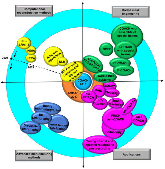
Figure 1.
Evolution of COACH along four directions: coded mask engineering, computational reconstruction methods, applications, and advanced manufacturing methods. The blue annular ring shows the regions of the latest developments from 2022 to 2024.
One primary research direction of CAI is the engineering of coded masks to improve the performance of CAI and obtain new capabilities. In 2017, lensless I-COACH (LI-COACH) was developed to simplify I-COACH [15]. In LI-COACH, the coded mask was engineered using the Gerchberg–Saxton algorithm [16] with Fresnel propagators to create controlled scattering and achieve a high signal-to-noise ratio (SNR) from bipolar holograms obtained from two camera shots. In LI-COACH, there is no additional optical element other than the phase mask, simplifying the configuration of I-COACH. In 2023, LI-COACH was implemented using a binary-coded mask designed using a modified binary search algorithm with an improved SNR [17]. Lensless CAI methods have been reported by different research groups [18,19,20]. In this research direction, in the same year, single camera shot I-COACH (SCS-I-COACH) was developed, where two uncorrelated quasi-random phase masks with equal and opposite linear phases were embedded in the same coded mask, and two intensity distributions were recorded simultaneously using a single image sensor. In SCS-I-COACH, the field of view (FoV) was sacrificed to achieve single-camera shot capability [21]. In the same year, in 2017, a conventional IDH technique called Fresnel incoherent correlation holography (FINCH) and COACH were combined to form a hybrid IDH technique that can be tuned between FINCH and COACH. A hybrid-coded mask was engineered by combining the phase masks of FINCH and COACH, and by tuning the ratio, the characteristics of the hybrid IDH can be tuned between non-linear (FINCH) and linear (COACH) imaging characteristics [12]. The phase mask was engineered to obtain sub-diffraction spots [22] and sparse dot patterns [23] that rendered an enhanced imaging resolution and improved the SNR, respectively. All the above research has been reviewed. This review focuses on the latest developments in the engineering of coded masks, which include depth-of-field engineering [24,25,26,27,28], spectral resolution engineering [28], both real-time and post-recording, and improvements in the SNR [29,30]. In this direction, SCS-I-COACH is no longer used for research and applications, as all the latest I-COACH methods require a single camera shot.
Another important direction of CAI evolution is the development of computational reconstruction algorithms. At the time of the inventions of COACH and I-COACH, image reconstruction was achieved using matched filter (MF) and phase-only filter (PoF) by cross-correlating the complex object and point object holograms obtained by projecting at least three camera recordings onto the complex space [31]. In 2018, the non-linear reconstruction (NLR) method was developed, which made single-shot imaging possible in I-COACH [32]. However, there are numerous deconvolution methods, such as the Lucy–Richardson algorithm (LRA) [33,34] and Wiener deconvolution [35], which can be applied to I-COACH and methods developed specifically for I-COACH by other groups [36,37,38,39,40]. In 2022, NLR was implemented within LRA to create the Lucy–Richardson–Rosen algorithm (LRRA), which has a convergence rate two orders faster than that of LRA, with a significantly improved SNR compared with both LRA and NLR [41]. More recently, two advanced algorithms named incoherent non-linear reconstruction with an iterative algorithm (INDIA) [42] and non-linear LRA [43] have been developed to improve the SNR even better than LRRA. Most reconstruction methods, such as LRA, Wiener deconvolution, NLR, and LRRA, have been reviewed thoroughly in our previous studies. In addition, with the development of new methods, previous methods, such as MF, PoF, LRA, and NLR, are no longer used in I-COACH. In this review, the latest methods, such as INDIA and NL-LRA, are discussed.
Another important research direction in CAI is the design and manufacturing of coded masks. From the time of its invention until 2019, I-COACH was implemented using SLM. However, after the development of advanced computational algorithms that allowed single-shot capability, the use of SLM was not needed. Therefore, since 2020, advanced manufacturing methods, such as photolithography, electron beam lithography, and femtosecond fabrication, have been used to manufacture coded masks. This not only reduces the cost but also the overall size of the imaging system. When this possibility was explored, a mask containing a quasi-random array of pinholes (10 cm × 10 cm) was fabricated using the photolithography technique [44]. Later, electron beam lithography and femtosecond fabrication methods were used for manufacturing small area-coded masks (5 mm × 5 mm) [45,46]. The above coded masks were amplitude-only and phase-only two-level elements. Recently, a greyscale photolithography method has been developed, which will be reviewed in this study. This greyscale lithography produces elements with high diffraction efficiency, and the fabrication process is quicker than the electron beam lithography method.
The final direction of CAI evolution involves various applications. It is not an exaggeration that I-COACH revolutionized the field of imaging, as the applications were numerous and diverse, affecting many important imaging technologies. I-COACH has been used to develop multidimensional imaging systems to image simultaneously along 3D space, spectrum, and polarization [47], partial aperture-based imaging systems [48] and telescopes [49], FoV extendable [50], axial and spectral resolution tunable imaging systems [27,28], super-resolution systems [51], and optical security systems [52].
The review consists of nine sections. Section 1 provides an outline of this review article, including significant milestones, recent breakthroughs, and associated applications in CAI. Furthermore, the latest research developments in CAI over the last few years are thoroughly discussed in Section 2, Section 3, Section 4, Section 5, Section 6 and Section 7. Section 2 elucidates the recent advancements in coded mask design and reconstruction algorithms in CAI. A brief overview of novel deconvolutional algorithms, such as NLR, LRRA, and INDIA, is provided. Furthermore, recently developed computational algorithms, such as NL-LRA-1 and NL-LRA-2, are thoroughly reviewed and demonstrated with simulation and experimental results. In Section 3, current techniques for implementing FINCH in the CAI framework are reviewed. Furthermore, our recent research, i.e., 5D-I-COACH, which depicts the five-dimensional (5D) imaging capabilities of CAI, along with 3D in space, polarization, and the spectrum, is reviewed in Section 4. Section 5 and Section 6 elaborate on the recently developed methods in CAI for engineering applications. In Section 5, two novel CAI-based methods, i.e., the incoherent hybrid imaging system (INCHIS) and post-ensemble generation with Airy beams for spatial and spectral switching (PEGASASS), are discussed and demonstrated for engineering the axial and spectral resolutions of an imaging system. Section 6 encompasses recent advances in CAI-based endoscopy techniques. In particular, our recently developed super-resolution correlating optical endoscopy (SCOPE) method, which involves high-resolution imaging and can be adapted to commercial endoscopy systems, is discussed. Section 7 is dedicated to fabrication methods in CAI. The diffractive optical element (DOE) fabrication techniques, such as photolithography and direct laser ablation, are reviewed in Section 7. The emerging trends, challenges, and future prospects in CAI are discussed thoroughly in Section 8 and Section 9.
2. Coded Aperture Imaging with Deterministic and Random Optical Fields and Non-Linear Lucy–Richardson Algorithm
Recent advancements in CAI have focused on optimizing coded mask (CM) design and reconstruction algorithms to improve the SNR, using deterministic and random optical fields [14,43,53]. In this section, we reviewed NL-LRA. There are two versions of NL-LRA: NL-LRA1 and NL-LRA2. NL-LRA1, developed for limited support images (LSIs), accelerates the convergence rate of the LRRA by enforcing a mask constraint within the iterative loop of LRRA. Moreover, NL-LRA2 improves noise suppression through entropy reduction, particularly for full-view images (FVIs). Both the NL-LRA1 and NL-LRA2 algorithms were tested in CAI using various CMs. The results of the new methods were compared with those of their parent methods, NLR [32] and LRRA [41], and it was confirmed that the new methods offer an improved SNR compared with that of the parent methods. The experimental studies revealed that NL-LRA1 performs well for LSIs and that NL-LRA2 performs well for FVIs. Both algorithms can also be simultaneously applied for LSIs, but not for FVIs.
The optical configuration and the optical setup are illustrated in Figure 2a,b; the optical setup records two intensity patterns. In the first step, a pinhole is placed at the object plane (Element 7), and the corresponding intensity pattern called the PSF is recorded by the image sensor. In the second step, the pinhole is replaced by the object at the same position, and the response-to-object-intensity (IO) is recorded. The CM, which can be phase-only (grayscale from 0 to 2π) or binary (0 or π), modulates the wavefront before it reaches the sensor. The object can be reconstructed by processing IPSF and IO using one of the deconvolution methods. The (n + 1)th reconstructed image of LRRA is given as , where is defined below and was defined previously. The symbol ‘’ refers to the NLR, which is given as
where A represents the PSF, B is the response-to-object intensity, and and are their Fourier transforms. This non-linear operation provides better contrast and noise suppression than conventional linear deconvolution does. LRRA initializes the solution with IO, allowing faster convergence.
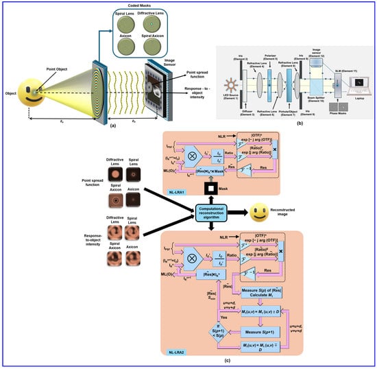
Figure 2.
Concept figure (a): Recording objects with different coded masks—diffractive lenses, spiral lenses, spiral axicons, and axicons—and reconstruction using non-linear Lucy–Richardson algorithms, (b) Schematic of the experimental setup. In the first step, in the setup only a pinhole is mounted, and in the second step, the pinhole is replaced by an object. (c) Schematic of NL-LRA1 and NL-LRA2.
Schematics of NL-LRA1 and NL-LRA2 are shown in Figure 2c. From the schematics in NL-LRA1, we can see that a mask is applied to refine the estimation, ensuring rapid convergence with an improvement of 70%. Additionally, NL-LRA2 optimizes the Fourier magnitude constraints and applies entropy minimization using , where S quantifies randomness and ϕ(u,v) represents the normalized intensity distribution. Minimizing entropy enhances depth reconstruction, contrast, and feature clarity while improving the SNR. By integrating NL-LRA1 and NL-LRA2, the method enhances image reconstruction accuracy, providing superior noise suppression and depth retrieval compared with traditional LRRA [41,43].
The experimental setup includes a high-power LED, optical elements such as an iris, diffuser, polarizer, refractive lenses, a beam splitter, SLM, and CMOS image sensor. The LED light was first passed through an iris and diffuser to control illumination, collected by a refractive lens, and polarized and directed to the SLM, where deterministic and random phase masks were displayed. The test object was the USAF Test Target, and a 50 μm pinhole for PSF recording was used. The collimated light passed through the beam splitter onto the SLM, and the resulting intensity patterns, IPSF, and object intensity IO were captured for computational reconstruction. The experimental results for 2D imaging of USAF object ‘3’ are presented in Figure 3. The phase masks of the deterministic and random optical fields are shown in row 1, and their corresponding IPSF and IO (zs = 5 cm) are shown in rows 2 and 3, respectively. The reconstruction results of the NLR, LRRA, NL-LRA1, and INDIA are shown in rows 4 to 7, respectively. As seen from the reconstruction results, the performance of NL-LRA1 is better than that of all the other reconstruction methods. Next, the experimental results with two digits, ‘3’ and ‘1’, are shown in Figure 4. The recorded IPSF and IO for different beams are shown in rows 1 and 2. The reconstruction results using LRRA and NL-LRA2 are shown in rows 3 and 4 of Figure 4.

Figure 3.
Row 1: Phase masks; Row 2: IPSF; Row 3: IO; Row 4: IR (NLR); Row 5: IR (LRRA); Row 6: IR (NL-LRA1); Row 7: IR (INDIA). The direct image of the object is shown at the bottom.

Figure 4.
Row 1: IPSF; Row 2: IO; Row 3: IR (LRRA); Row 4: IR (NL-LRA1). The direct image of the object is shown at the bottom.
As proof of study, we calculated the entropy for 2D and 3D imaging, the results of which are shown in Figure 5. Figure 5a shows the entropy plot for the different CMs to quantify the results from all the reconstruction methods discussed [43]. Additionally, the performance of INDIA is identical to that of NL-LRA1. This is because the noise is not high in NL-LRA1, and the amplitude and phase information of NL-LRA1 are fed as inputs to INDIA. Furthermore, the entropy plot corresponding to Figure 4 is shown in Figure 5b. In NL-LRA2, a major advantage is that it can achieve the best results by entropy optimization blindly. However, NL-LRA2 might not benefit from having a shorter execution time because the time gained in reducing the number of iterations in LRRA is almost utilized during entropy optimization. Therefore, the main advantage is the better SNR measured by reduced entropy.
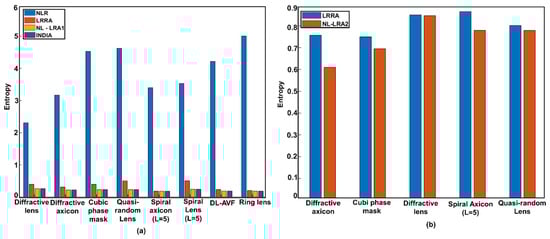
As per the results of our study in both scenarios, in the case with all DOEs, the number of iterations required for NL-LRA1 and NL-LRA2 are comparatively less than that of LRRA. Compared with NLR and LRRA, NL-LRA1 and NL-LRA2 yield results with the lowest entropy. In summary, recent advancements in CAI have focused on optimizing both coded mask design and computational reconstruction algorithms. The introduction of NL-LRA, with its two variations, NL-LRA1 and NL-LRA2, has significantly improved noise suppression and computational efficiency over traditional LRRA methods. Experimental validation demonstrated that NL-LRA achieves higher SNRs, faster convergence, and enhanced reconstruction accuracy, making it a promising approach for 3D imaging and low-light applications. These developments highlight the potential of structured optical fields and advanced deconvolution techniques in expanding the capabilities of CAI.
3. Fresnel Incoherent Correlation Holography Implemented in the Framework of Coded Aperture Imaging
Fresnel incoherent correlation holography (FINCH) is an IDH method based on the self-interference principle, developed for the first time that uses a spatial light modulator for 3D imaging applications. FINCH requires a spatially incoherent light source. In FINCH, the light from every object point is split into two beams, spherical and plane beams, or two spherical beams, and interferes with the formation of self-interference holograms. FINCH requires a minimum of three camera shots of three self-interference holograms with phase shifts θ = 0, 2π/3, and 4π/3. The recorded FINCH holograms are projected into the complex space to obtain a complex hologram, which is then numerically backpropagated to reconstruct the object information without the twin image and bias terms. The first version of FINCH, as described in [54], inherently has superior lateral resolution. However, FINCH has lower axial and temporal resolutions, light throughput, and SNR than direct imaging does. FINCH was later applied to realize a fluorescence 3D holographic microscope [55]. The advancements of FINCH are presented next. The super-resolution capability of FINCH was achieved with perfect beam overlap at the image sensor [56], resulting in an enhanced resolving power with the same numerical aperture (NA). In FINCH, resolution enhancement is achieved by shaping the modulation transfer function (MTF) within the spatial frequency limits set by the NA [57]. In contrast, the structured illumination (SI) approach modifies the bandwidth of the MTF [58]. In a direct incoherent imaging system, the MTF has a high response for low spatial frequencies and a low response for high spatial frequencies. The MTF of FINCH at optimal operating conditions has a uniform response for all spatial frequencies [57]. However, the MTF of the SI is expanded such that it retains the characteristics of the direct imaging MTF, which hinders the full potential of the SI. Since FINCH possesses an optimal MTF, it can be utilized as a base imaging system [8]; this can be used as a platform for applying other super-resolution technologies, such as SI [51,59]. To enhance the temporal resolution, spatial multiplexing approaches were used, as in [60,61], at the cost of a lower FOV. The polarization multiplexing technique presented in [62] simultaneously captures holograms for phase shifts of 0, π/2, π, and 3π/2, resulting in a high temporal resolution but a low SNR, and there is a need for a polarization-sensitive image sensor. FINCH, based on a bifocal lens, was reported for point objects [63]. Further advancements in FINCH are presented in [1,7,8].
Later, COACH was developed and reported to have improved axial resolution [11] compared with FINCH. In COACH, interference occurs between object beams that are diffracted from the same object point, wherein they are made to pass through a quasi-random CPM, and IOHS are recorded for phase shifts θ = 0°, 120°, and 240°. Similarly, IPSHS are recorded for identical conditions. The reconstruction was carried out by cross-correlating the IPSH with the IOH. Later, the NLR was developed to improve the SNR of the reconstruction [32]. FINCH was combined with the NLR, enabling single-shot capability, with a one-time recorded IPSH reconstructed object image for the recorded IOH at the same axial location [64].
In our research presented in [65] we implemented FINCH in the CAI framework with three recently developed computational methods, namely, the transport of amplitude into phase based on the Gerchberg–Saxton algorithm (TAP-GSA), LRRA, and computational point spread function engineering (CPSFE) techniques. The TAP-GSA is a recently developed algorithm [66] for designing phase masks, wherein two or more pure phase functions are combined, forming a complex function. The magnitude of this complex function is transferred into the phase to obtain a phase-only function that is equivalent to a complex function with high light throughput. LRRA is a computational reconstruction algorithm [41] that is proven to reconstruct images with a higher SNR than the NLR and is therefore used in this study. The CPSFE technique enables the lateral resolution limit to be shifted from the pinhole size to the limit determined by the NA of the imaging system. Additionally, the inherent problems in CAI in recording IPSH are solved through this approach. If the recorded IPSH is smaller than the diffraction-limited spot size imposed by the NA, there is no problem. However, a small pinhole allows only a few photons, so the recorded intensity level drops close to the noise level of the image sensor. Therefore, in most imaging systems, a pinhole much larger than the diffraction-limited spot size imposed by the NA is used, resulting in a lower system resolution. Therefore, with the help of CPSFEs, an ideal IPSH is engineered that can resolve features beyond the size of the pinhole. The proposed FINCH as CAI with three computational algorithms, in addition to solving all the above-mentioned problems of FINCH, can be implemented with a passive diffractive element, excluding the need for a vibration isolation system and additional optical components.
The optical configuration of FINCH as a CAI is presented in Figure 6. In this study, the phase masks consisting of two diffractive lenses were designed using TAP-GSA with degrees of freedom (DoF) of 98%, where DoF is the measure of number of pixels replaced in the phase matrix to the total number of pixels in the matrix as shown in sub-image 1 of Figure 6 [65]. The light from the object point is split into two beams, which are differently modulated using phase masks designed using TAP-GSA displayed on the SLM. The two beams are then interfered with to form a self-interference hologram. The IPSH and IOH are recorded one after the other by replacing the point object (pinhole) with a test object, as shown in sub-image 2 in Figure 6. The reconstructed object (IR) with LRRA is given as , where ‘’ represents the LRRA operator with optimal values of α, β, and i, where α and β are the powers of the magnitudes of the spectrum of the matrices, and i is the number of iterations. The object reconstructed via LRRA possesses improved resolution and SNR.
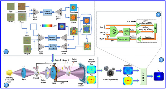
Figure 6.
Optical configuration of FINCH as a CAI system with three computational algorithms: (1) phase mask design using TAP-GSA and (2) optical FINCH experiment and recording of IPSH and IOH. (3) The CPSFE technique is used to obtain the ideal IPSH and (4) computational reconstruction using LRRA.
The experiment used for this study was adapted from [65]. To push the resolution limit to the limit set by the NA, an ideal IPSH is engineered using the CPSFE technique, as shown in Figure 6. The ideal IPSH is the point spread hologram estimated from the IPSH recorded using a pinhole with a diameter larger than the diffraction-limited point size. In CPSFE, the recorded IPSH and direct image of the 50 μm pinhole are processed using LRRA to engineer the ideal IPSH. The ideal IPSH is engineered using CPSFE and is given as , where ‘’ represents the LRRA operator, IPSH_recorded is the point spread hologram recorded for a larger pinhole size, and Ip is the direct image of the pinhole. From the engineered ideal IPSH and recorded IOH, the object image is reconstructed. The phase masks designed using TAP-GSA are displayed on the SLM, and the recorded IOH and IPSH are shown in Figure 7a and Figure 7b, respectively. The ideal IPSH is engineered from the recorded IPSH using the direct image of the pinhole, as shown in Figure 7c. The direct image of the object is shown in Figure 7d. The reconstructed results corresponding to the recorded IPSH and engineered IPSH are shown in Figure 7e and Figure 7f, respectively. The presented reconstruction results corresponding to the engineered ideal IPSH are better than the results of the recorded IPSH.

Figure 7.
(a) IOH and (b) IPSH recorded using a pinhole of 50 μm for the phase mask designed using TAP-GSA. (c) Engineered ideal IPSH. (d) Direct imaging result. (e) Reconstruction result using the recorded IPSH shown in (b). (f) Reconstruction result using the engineered ideal IPSH shown in (c).
The superior axial resolution capabilities of FINCH as a CAI compared with conventional FINCH are presented next. The experimental details are presented in [65]. The phase mask designed using TAP-GSA for a 98% DoF is shown in Figure 8a and is used for FINCH as a CAI experiment. Here, two test objects from the USAF resolution chart were taken, objects “1” and “3” from group 5, which were placed at different depths, zs = 5 and 5.6 cm, and the IPSH was recorded with a pinhole of 25 μm. The IPSHS values recorded for the two depths are shown in Figure 8b,c, and the recorded IOH values are shown in Figure 8d. The direct imaging result is shown in Figure 8e. The reconstruction result of FINCH as a CAI is obtained using the IPSHS shown in Figure 8b,c is displayed in Figure 8f,g. To compare the imaging capabilities of FINCH as a CAI with those of conventional FINCH under similar conditions, the conventional FINCH was performed for phase masks designed using TAP-GSA for 58% DoF. During the study, conventional FINCH did not yield an optimal result for all values of the DoF, so different masks were tried for conventional FINCH; however, FINCH, as the CAI, generated consistent results for different values of the DoF. In the conventional FINCH experiment, three phase-shifted holograms for relative phase shifts θ = 0, 2π/3, and 4π/3 are recorded and reconstructed using numerical backpropagation. The reconstruction result of conventional FINCH is presented in Figure 8h, where both objects “3” and “1” are in focus, resulting in lower axial resolution. However, the reconstruction results of FINCH as a CAI, presented in Figure 8f,g, possess superior axial resolution. Our method effectively retrieves the object’s image at different axial locations with the help of IPSHS and IOHS recorded at different optical depths. When an IPSH is processed with an IOH recorded at the same depth using LRRA, the object’s image is accurately reconstructed.

Figure 8.
(a) Phase mask generated using TAP-GSA for 98% DoF. IPSH recorded for (b) zs = 5 cm and (c) zs = 5.6 cm. (d) IOH for the object at two depths. (e) Direct image when the two objects were mounted in the same axial plane. (f) Reconstruction result using the recorded IPSH for zs = 5 cm is shown in (b). (g) Reconstruction result using the recorded IPSH for zs = 5.6 cm is shown in (c). (h) Reconstruction result for conventional FINCH.
In this study, FINCH as a CAI is implemented with three computational algorithms, namely, the TAP-GSA, LRRA, and CPSFE techniques, thereby enhancing temporal and axial resolutions and the SNR while preserving higher lateral resolution. Additionally, the lateral resolution–SNR trade-off challenge of CAI in recording IPSH is solved through a CPSFE technique. Therefore, the system’s resolution is extended beyond the size of the pinhole used for recording IPSH to a limit defined by the NA. FINCH as a CAI enables the acquisition of three-dimensional and super-resolved object images. These enhanced imaging capabilities will benefit FINCHscope in the future.
4. Single Shot 5D-I-COACH
I-COACH has significantly impacted the field of CAI because of its multidimensional imaging capabilities. Previously developed CAI techniques, such as FINCH [54] and COACH [11], rely on two-beam interference because the object information is encoded in the phase function while the magnitude remains uniform. However, two-beam interference has numerous limitations, including the need for vibration isolation and minimizing the optical path difference between the two beam paths. I-COACH overcomes these challenges by enabling 3D imaging without requiring two-wave interference. This interference-free version of COACH is called Interferenceless COACH (I-COACH) [13], making it a more advanced and robust computational imaging technique. One major evolution of I-COACH has been its ability to record multidimensional information in just one or a few camera shots by integrating spatial and spectral data, leading to advancements in 3D-I-COACH [67] and 4D-I-COACH [44,68].
Polarization, which provides valuable object-specific information, is another crucial characteristic of light. Polarization-based imaging techniques offer significant advantages, including birefringence measurement and information multiplexing. However, in these methods, polarization-related changes are primarily observed through intensity variations, which alone are not sufficient parameters for a comprehensive analysis [69,70,71,72]. A significant advancement was made when polarization changes were effectively transformed into blur in incoherent digital holography using two polarization-sensitive phase-only spatial light modulators (IDHs with TPP-SLMs) with multiple exposures. This method eliminates the need for polarization filters and enables the simultaneous capture of both 3D and polarization information, storing them in a single hologram [73,74]. However, all the above-mentioned methods and techniques still face challenges regarding multiple camera shots, weak polarization discrimination, and complicated experimental configurations. We address previous challenges in our recent research, which utilized the polarization-dependent phase modulation characteristics of SLM. Unlike previous techniques, our approach requires only one SLM. It allows single-shot imaging with high polarization discrimination. We refer to this method as single-camera-shot 5D I-COACH along 3D space, spectrum, and polarization [47].
In 5D-I-COACH [47], a significant polarization-dependent discrimination between orthogonal polarization states was achieved using two optical modulators, i.e., a phase DOE (spiral lens with topological charge ‘5’), which was displayed on the SLM, and a fabricated amplitude DOE (quasi-random diffractive lens). Each DOE contributes to the precise control of polarization encoding, leveraging the polarization modulation characteristics of the SLM. The optical setup for 5D I-COACH is shown in Figure 9.
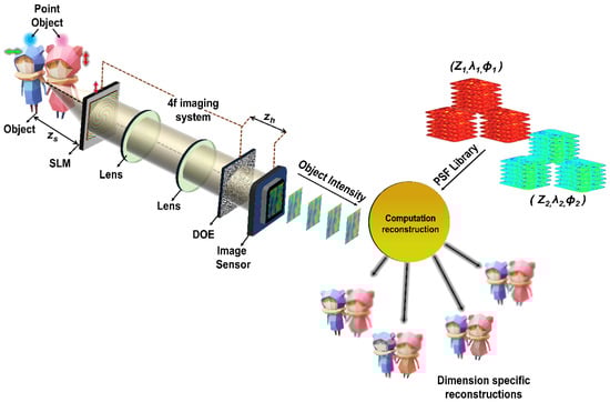
Figure 9.
Optical configuration of 5D-I-COACH. SLM—Spatial light modulator; DOE—diffractive optical element; PSF library—Point spread function library; green and red arrows indicate orthogonal polarization orientations.
The light emitted by the object passes through SLM, in which the phase DOE (spiral lens with a topological charge of 5) is displayed. The light is then propagated to the second DOE (QRDL) using a 4f imaging system consisting of two refractive lenses. The PSF and object intensity distributions were recorded using an image sensor.
Let us consider a single point in the object plane at with an intensity . The complex amplitude after the first refractive lens of a focal length f is where and are the quadratic and linear phase functions, respectively, and C1 is a complex constant. The object and image distances are zs and zh, respectively. At the SLM, the phase function of is displayed. A Fourier-based GSA [75] was used to design a second-amplitude DOE (QRDL), whose phase distribution can be expressed as , with an amplitude of all values. After ~50 iterations, the phase matrix stabilized, was binarized, and formed an amplitude-only QRDL. The DOE characteristics were switched using the polarization-dependent modulation of the SLM.
In the first case, when the initial polarization is along the active axis of the SLM, it undergoes dual modulation, i.e., both DOEs are active. When the polarization orientation is orthogonal to the active axis of the SLM, the light undergoes only one modulation, which is due to the second DOE (QRDL). The point intensity distribution for a point at zh DOE over the plane rh for two orthogonal polarization orientations is given by
where ‘’ is a 2D convolutional operator. If the system is linear and shift invariant, and the object is considered a collection of N points, the PSF and response-to-object intensity distribution can be expressed as
Here, k1, k2, and k3 are indices that run over the number of depths, wavelengths, and polarization states, respectively.
The object image is reconstructed by processing the response-to-object intensity distribution with the corresponding PSFs using novel Lucy–Richardson–Rosen algorithm (LRRA) and incoherent non-linear deconvolution using an iterative algorithm (INDIA), expressed as
where ‘’ is the non-linear correlation operator given as , where U and V are the Fourier transforms of u and v, respectively.
By optimizing the experimental design of the imaging system, we obtained maximum discrimination between the orthogonal polarization states while efficiently maintaining light throughput. The imaging system was trained using a pinhole with a diameter of 100 μm. Two objects, elements 2 and 3 of Group 2 of the USAF resolution targets, were used. The axial distance between the two objects was shifted by 1 cm. In the first step, a PSF library and object intensities were recorded along the five dimensions. In the second step, object information is recovered through novel deconvolution algorithms such as the Lucy–Richardson–Rosen algorithm (LRRA) [41] and incoherent non-linear deconvolution using an iterative algorithm (INDIA) [42].
The experimental results of the polarization-sensitive I-COACH method are shown in Figure 10. The first two columns (C1, C2) of Figure 10 represent the pinhole intensity distribution and object intensity distribution corresponding to two polarization states, 0 and π/2, at two depths in Figure 10a and Figure 10b, respectively. The last two columns (C3, C4) depict the reconstruction results for the LRRA and INDIA. The reconstruction results clearly demonstrated significant polarization discrimination between orthogonal polarization states. The best reconstruction was achieved for the same polarization states of pinhole and object intensity distributions, unlike the cross-polarization states.
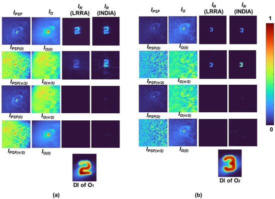
Figure 10.
Polarization-sensitive I-COACH results (a) for objects O1 (left) and (b) O2 (right) at different depths (zs = 5 cm and zs = 6 cm, respectively). Each column represents (C1) IPSF at polarization states 0 and π/2, (C2) recorded the IO at the same polarization state, (C3) reconstruction using LRRA, and (C4) reconstruction using INDIA. The final row shows the direct images (DIs) of the objects for reference. The color bar represents intensity variations in the images. Adapted from [47].
I-COACH was successfully demonstrated experimentally for 4D imaging (3D space, spectrum) or (2D space, spectrum, and polarization) [47]. We further explored the 5D imaging capabilities of I-COACH, which include 3D space, spectrum, and polarization. The experimental results of 5D-ICOACH are shown in Figure 11, in which the object intensity distribution IO at the center at two polarization states (0 and π/2) is shown at two depths. (zs = 5 cm and zs = 6 cm, Δz = 1 cm), and two wavelengths (G and R) were computationally stitched into a single 2 × 2 submatrix, where each element represents a unique combination of these five dimensions. In the lateral sections, the recorded IPSFs—IPSF (0, G, zs = 6 cm), IPSF (0, R, zs = 5 cm), IPSF (π/2, G, zs = 6 cm), and IPSF (π/2, R, zs = 5 cm)—are shown as (a), (b), (c), and (d), respectively. The corresponding reconstruction results were achieved by cross-correlating the PSH library with the object intensity distribution using LRRA, referred to as IR (LRRA). The experimental results of 5D I-COACH confirm that depth, wavelength, and polarization information can be extracted from a single recording. In the figure, white arrows indicate orthogonal polarization states, with horizontal arrows representing 0 polarizations and vertical arrows representing π/2 polarizations. The analysis reveals strong wavelength and polarization discrimination; however, the depth discrimination is weaker, leading to minor blurring. This blurring effect is specifically marked by the white circle in the IR (LRRA) representation. These findings demonstrate that 5D imaging was successfully achieved with a single camera shot, enabling implementation at the same speed as commercial image sensors. The proposed method can be considered a 6D I-COACH for recording 5D information in real time. This technique takes advantage of the polarization-dependent light modulation capabilities of the SLM. It can be applied for recording dynamic scenes, ultimately allowing for the creation of holographic videos of moving objects, making it a highly effective and promising approach.
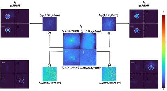
Figure 11.
Five-dimensional-ICOACH across space, spectrum, and polarization: IO matrix illustrating polarization states (horizontal: 0, vertical: π/2), depths (zs = 5, 6 cm), and wavelengths (G, R). The IPSF variations and IR (LRRA) reconstruction results are shown under different dimension specification conditions. (a) IPSF (0, G, zs = 6 cm), (b) IPSF (0, R, zs = 5 cm), (c) IPSF (π/2, G, zs = 6 cm), (d) IPSF (π/2, R, zs = 5 cm). Adapted from [47].
5. Engineering Axial Resolution Post-Recording
The possibility of engineering axial resolution in real time was demonstrated by recently reported studies [24,25,26,29] through the use of advanced coded phase masks [24], Bessel speckles [25], random multiplexing of scattered Airy beams [26], and self-rotating beams [29]. From the above studies, we know that axial resolution can be engineered in real time, which also leads us to consider the important research question whether axial resolution can be engineered after recording pictures and videos. In this section, we reviewed two imaging methods capable of engineering axial resolution post-recording. Hybridization is a powerful tool for generating mixed properties that do not naturally exist when two different elements are combined. In 2024, a holographic hybrid imaging method called an incoherent hybrid imaging system (INCHIS) [27] was developed for the first time to engineer axial resolution without affecting lateral resolution post-recording. INCHIS is a simple and valuable computational imaging method that involves a unique optical recording and computational reconstruction process that allows engineering of the axial resolution post-recording. In the optical recording process, a scene is recorded collinearly using a refractive lens and a refractive axicon. The recorded images are combined with different strengths, and the resulting image is processed with a point spread function (PSF) formed by combining similar strengths of the PSFs of a lens and an axicon using a computational reconstruction algorithm to reconstruct the scene with a desired axial resolution. By varying the strengths while combining the two recorded images, the axial resolution is engineered post-recording.
A schematic of the INCHIS method proposed in [27] is shown in Figure 12a. In INCHIS, the light emitted from a scene located at different depths is modulated using two passive refractive optical element lenses and axicon collinearly, and the corresponding object intensity distributions (OIDs) and are recorded individually by two image sensors. Two variables, namely, S1 and S2, are used to control the strengths of and . The hybridization principle is applied to generate the hybrid OIDs by summing and with different strengths S1 and S2, which is given as . The same process is repeated by replacing the object with a point object, and the corresponding PSFs and are recorded. Similarly, the hybridization principle is applied, and the corresponding hybrid PSFs are generated as . The values of S1 and S2 are controlled as and . The object and image distances are provided by zs and zh, respectively. The object information is reconstructed by processing the corresponding PSFs and OIDs of the lens, hybrid states, and axicon using the LRRA. This allows engineering axial resolution post-recording between the axial resolution ranges of a lens and an axicon.
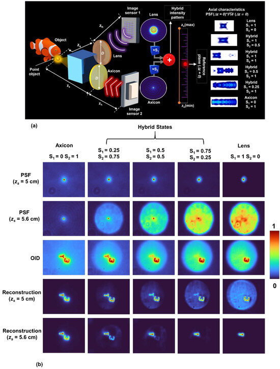
Figure 12.
(a) Optical configuration of the INCHIS-H2 method for engineering the axial resolution without affecting the lateral resolution post-recording. (b) Three-dimensional imaging experimental results of INCHIS-H2. Row 1: PSF at depth (zs = 5 cm); Row 2: PSF at depth (zs = 5.6 cm); Row 3: combined object intensity distribution (OID) corresponding to depth (zs = 5 cm) and (zs = 5.6 cm); Row 4 and Row 5: reconstruction results by LRRA at depth (zs = 5 cm) and (zs = 5.6 cm) corresponding to the axicon, hybrid states, and lens, respectively. Adapted from [27].
For the experimental demonstration of INCHIS, an incoherent light source with a wavelength of λ = 660 nm is used for illuminating the two test objects, digit ‘3’ and digit ‘1’, chosen from Group 5 of the Thorlabs Negative 1951 USAF Test Target. The and corresponding to objects with the digit ‘3’ and digit ‘1’ were recorded at depths of (zs = 5 cm) and (zs = 5.6 cm) by the image sensor using the two optical elements lens and axicon. The are generated with the different strength combinations given as , , and . A 50 μm pinhole was used to record and at both depths (zs = 5 cm) and depths (zs = 5.6 cm). Similarly, are generated with the strength combinations given as , , and . The image distance was zh = 17.8 cm. The 3D imaging experimental results of INCHIS-H2 are shown in Figure 12b. The first and second rows show the PSFs at depths of (zs = 5 cm) and (zs = 5.6 cm), the third row shows the combined OID corresponding to both depths of (zs = 5 cm) and (zs = 5.6 cm), and the fourth and fifth rows show the reconstruction results by LRRA at depths of (zs = 5 cm) and (zs = 5.6 cm) for the axicon state, hybrid state, and lens, respectively. From the reconstruction results corresponding to both depths (zs = 5 cm) and (zs = 5.6 cm), in the case of the axicon (S1 = 0 and S2 = 1), both test object digits ‘3’ and ‘1’ are focused, which demonstrates low axial resolution. In the first hybrid state (S1 = 0.25 and S2 = 0.75), the test object that is on the plane of interest is focused, and the test object that is not in the plane of interest gradually begins to blur. In the next hybrid states, (S1 = 0.5 and S2 = 0.5) and (S1 = 0.75 and S2 = 0.25), the test objects that are not in the plane of interest blur more, which demonstrates an increase in axial resolution. Finally, in the lens case (S1 = 1 and S2 = 0), the test object corresponding to the plane of interest remains focused, and the test object that is not in the plane of focus is maximally blurred, demonstrating a high axial resolution. The axial resolution was engineered between the axial resolution limits of the axicon and the lens. In all the above cases, the lateral resolution remained constant. The significant advantage of engineering axial resolution post-recording using INCHIS is the ability to focus and defocus object information at different depths with respect to one another.
After the development of INCHIS, another novel CAI method called post-ensemble generation with Airy beams for spatial and spectral switching (PEGASASS) [28] was reported to engineer both axial and spectral resolutions post-recording simultaneously. In the PEGASASS method, four unique cubic phase masks (CPMs) were designed for modulating the light from an object point into Airy intensity distributions with different 3D paths and recorded one after the other using an image sensor. Next, the PSFs were recorded in the same fashion, and the axial and spectral resolutions were engineered by creating an ensemble of synthetic point spread functions (S-PSFs) and synthetic object intensity distributions (S-OIDs) by summing the corresponding PSFs and OIDs recorded using different CPMs. The axial and spectral resolutions increase proportionally with the number of Airy distributions that are summed to create the ensemble.
The optical configuration and post-engineering process of PEGASASS are shown in Figure 13a,b. In the PEGASASS method [28], the light from the object is modulated into Airy distributions with different 3D paths by displaying four CPMs one after the other on the spatial light modulator (SLM), and the corresponding OIDs are recorded by the image sensor at times T1 to T4. The same recording process was repeated by replacing the object with a point object, and the corresponding PSFs were recorded. After recording, ensembles of and are constructed by summing the individual PSFs and OIDs, which are given as and , where is the strength of the kth intensity distribution. The variable M is employed to control the number of Airy distributions within the constructed ensemble, and the integer k is varied from 1 to M, corresponding to times Tk=1 to Tk=M. When M = 1, a single Airy distribution consists of the ensemble, and very low axial and spectral resolutions exist. When M = 4, four Airy distributions are summed to form the ensemble, and high axial and spectral resolutions are obtained. The chaos within the constructed ensemble is controlled by intermediate values between M = 1 and M = 4. The object information with a particular wavelength (λ) and depth (z) can be reconstructed from by using the corresponding by LRRA. This allows engineering both axial and spectral resolutions simultaneously post-recording.

Figure 13.
(a) Optical configuration of the PEGASASS method for engineering both the axial and spectral resolutions without affecting the lateral resolution post-recording. (b) The post-engineering process of PEGASASS. Adapted from [28].
For the experimental demonstration of PEGASASS, an incoherent light source with a wavelength of λ = 660 nm is used for illuminating the two test objects, digit ‘4’ and digit ‘1’, chosen from Group 3 of the Thorlabs Negative 1951 USAF Test Target. The object digit ‘4’ was recorded at depth (zs = 5 cm), and then the object digit ‘1’ was recorded at depth (zs = 5.3 cm) by the image sensor by displaying the four CPMs one after the other on the SLM. The image distance was (zh = 17.8 cm). A 50 μm pinhole was used to record the PSFs at both depths (zs = 5 cm) and depths (zs = 5.3 cm). The entire process was repeated by switching the light source to a wavelength of λ = 532 nm. The 4D imaging experimental results of PEGASASS are shown in Figure 14. Columns 1–4 show the S-PSF corresponding to (zs = 5 cm and λ = 532 nm), (zs = 5.3 cm and λ = 633 nm), (zs = 5.3 cm and λ = 532 nm) and (zs = 5 cm and λ = 633 nm); column 5 shows the S-OID, and columns 6–9 show the reconstruction results by LRRA corresponding to (zs = 5 cm and λ = 532 nm), (zs = 5.3 cm and λ = 633 nm), (zs = 5.3 cm and λ = 532 nm), and (zs = 5 cm and λ = 633 nm) for M = 1 to M = 4, respectively. The reconstruction results indicate that the object information at a particular depth and wavelength can be extracted from the S-OID using the corresponding S-PSF. The ability of PEGASASS allows us to engineer both the axial and spectral resolutions simultaneously post-recording by controlling the chaos within the ensemble between M = 1 and 4.
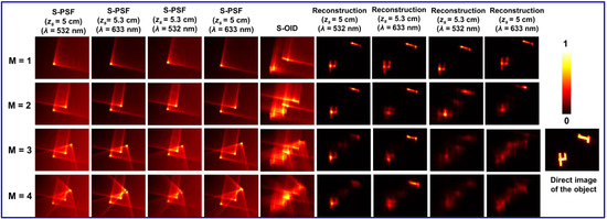
Figure 14.
Four-dimensional imaging experimental results of the PEGASASS. Column 1: Synthetic-point spread function (S-PSF) (zs = 5 cm and λ = 532 nm); Column 2: S-PSF (zs = 5.3 cm and λ = 633 nm); Column 3: S-PSF (zs = 5.3 cm and λ = 532 nm); Column 4: S-PSF (zs = 5 cm and λ = 633 nm); Column 5: Synthetic-object intensity distribution (S-OID) and Columns 6–9: reconstruction results by LRRA corresponding to (zs = 5 cm and λ = 532 nm), (zs = 5.3 cm and λ = 633 nm), (zs = 5.3 cm and λ = 532 nm) and (zs = 5 cm and λ = 633 nm) for M = 1, M = 2, M = 3, and M = 4, respectively. The direct image when both objects are at the same depth is shown on the RHS. Adapted from [28].
6. Coded Aperture Imaging for Endoscopic Applications
Endoscopy is a widely used minimally invasive diagnostic tool that allows us to investigate the internal organs of the human body [76,77,78]. Modern endoscopy systems are more advanced than other diagnostic tools because of their ability to perform super-resolution imaging, chromoendoscopy, biopsy, surgery, microscopy, etc. [78,79]. Most of the developments in endoscopy thus far are based on the direct imaging mode, i.e., the image of the object is directly recorded by an image sensor. However, few studies have attempted indirect imaging modes with multimode fibers thinner than usual endoscopy tubes and fiber bundles [80,81]. In recent years, several CAI-based endoscopic techniques have been reported [82,83]. Recently, we proposed a CAI-based endoscopic method called Superresolution Correlating OPtical Endoscopy (SCOPE) [83].
Figure 15 represents the SCOPE optical arrangement and the computer reconstruction procedure. The imaging process in SCOPE entails multiple recordings of the PSF and object by moving the endoscope tip around the target. The images recorded in the new spatial locations contain higher spatial frequencies of the objects that are not captured during regular recording. The recorded PSFs and recorded object intensities are arranged in a large matrix and processed using deconvolution algorithms. The reconstructed image has higher lateral resolution than the regular endoscopic image.
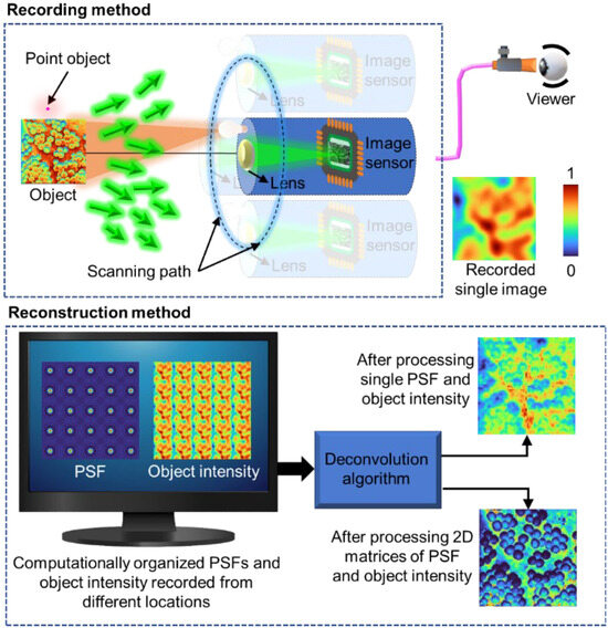
Figure 15.
Optical recording configuration and computational reconstruction configuration of SCOPE. Adapted from [83].
SCOPE was experimentally demonstrated using a basic I-COACH experimental setup, as shown in Figure 16. Group 4 elements of 1DS1N—Negative 1951 USAF Test Target, Ø1 were used as test objects (O), and a pinhole with a diameter of 25 μm was used to record IPSF. The endoscopic system was mimicked by designing a lens array mask (LAM) for SCOPE by stitching 4 × 4 = 16 sub-apertures and was displayed on the SLM.
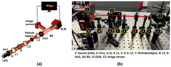
Figure 16.
Experimental configuration of SCOPE. (a) Schematic of the experimental setup and (b) photograph of the experimental setup. Adapted from [83].
Figure 17a–d shows the (a) combined aperture mask (CAM) (4 × 4), (b) LAM (4 × 4), (c) recorded PSF for the LAM, and (d) object response intensity (ORI) for the LAM. The recorded ORIs for the CAM and ORI for direct recording using regular endoscopy are presented in Figure 17e,f, respectively. The reconstruction results for regular endoscope imaging and SCOPE for the test object (O) using LRRA are shown in Figure 17g,h. Furthermore, quantitative measurements, such as the cross-section line profile and FWHM, are shown in Figure 17i,j, respectively. The minimum value of the FWHM was obtained in SCOPE, which indicates the higher spatial resolution in SCOPE as compared to that of the endoscopy method based on direct imaging. The experimental results of SCOPE confirmed the resolution enhancement for SCOPE compared with direct endoscope recording. SCOPE opened new possibilities for using CAI techniques in optical endoscopy for resolution improvement.

Figure 17.
Experimental results for SCOPE. (a) CAM (4 × 4), (b) LAM (4 × 4), (c) recorded PSF using LAM, (d) recorded ORI using LAM, (e) ORI using CAM, (f) ORI via regular endoscope, (g) regular endoscopy using LRRA, (h) SCOPE using LRRA, (i) line plot for the region of interest (ROI) (blue dashed line shows the data extraction location for the line plot), (j) FWHM plot corresponding to (i). DICAM: direct imaging with combined aperture mask. Adapted from [83].
7. Fabrication of Optical Microstructures
Fabrication of coded masks (CMs) is a crucial process in CAI because of its multidisciplinary applications. There are different methods for fabricating complex diffractive optical elements (DOEs). In general, successful methods allow for low-cost production, ensure accuracy, are fast, flexible, and suitable for a wide range of materials, can cover large areas, and are compatible with current semiconductor manufacturing technologies [84,85]. Some of the commonly used DOE fabrication techniques are discussed in subsequent subsections.
7.1. Machining Processes
High-precision DOEs have relied on well-established machining techniques, such as grinding, grooving, and turning [84]. Diamond machining allows direct prototyping of refractive, reflective, and diffractive elements without post-processing. For example, diamond turning is a commonly used method for the fabrication of harmonic DOEs [86]. Often, DOEs must also be transparent over a wider spectrum of wavelengths that extend from the deep ultraviolet to the long-wave infrared, which is why brittle materials such as fused quartz, calcium, or barium fluoride are necessary. In such cases, ultra-precise diamond wheel grinding can be used. On the other hand, an inherent challenge is maintaining the form accuracy and sharpness of the tool throughout the entirety of the process due to wear. However, owing to the complexity caused by the loss of symmetry of modern DOEs, these (mechanical) methods require an increase in the number of machining axes to maneuver the diamond tool to produce freeform surfaces. In general, the ability to flexibly generate discontinuous structured surfaces remains challenging for current machining processes. Therefore, these methods are not very flexible for converting complex theoretical asymmetric designs into functional products, and more novel approaches are needed.
7.2. Direct Laser Ablation
Ablative beam processes allow direct writing on the surface of the substrate, generating shapes by selectively removing material. The material begins to decompose under the influence of heat, melts, and evaporates as chemical bonds break. This method has the ability to process small details with high aspect ratios, is suitable for various materials, and is fast and flexible. However, the quality of laser-removed surfaces is generally poor, and this method is best suited for processing 2D (binary) structures, although some 3D capabilities can be achieved by controlling the power of the laser during processing. A shorter pulse duration could improve the ablation quality by minimizing thermal damage and surface roughness. For this purpose, nanosecond or femtosecond pulsed lasers are preferred. For example, clean and sharp ablations were performed via a femtosecond laser on a calcium fluoride substrate covered with Cr/Au (10/100 nm) layers. Multiple passes with different pulse densities and pulse powers were used to remove gently redeposited material without causing damage to the substrate. Each pass consisted of concentric circle ablations with increasing radii, forming a continuous disk. It has also been shown that the shortest focal length of 9 mm is achieved with compact photon sieve focusing elements on fused quartz substrates by femtosecond direct laser ablation. This shows great potential for this fabrication method for producing advanced applications that require precise depth control in wide-band cap materials [87].
7.3. Lithography
Lithography is the process of transferring patterns from a mask to a radiation-sensitive material (called resist) on a substrate. Depending on the type of resist (positive or negative), exposure to light, ions, or electrons, etc., renders resists either soluble or insoluble in the developing solution (see Figure 18). Although the (photo)lithography process requires cleanrooms, expensive chemistry, etc., it is fast, covers large areas, has high precision and resolution, and is suitable for brittle substrates, making it a promising method for fabricating optical microsystems at present. The newer generation of photolithography devices also operates without masking, i.e., a digital mask is used. The pattern is transferred to the resist using either a UV laser diode or UV LED and Digital micro-Mirror Device (DMD®) arrays [88], which makes this method more flexible and faster to produce at the wafer scale than e-beam lithography is. In the latter case, conductive substrates are also needed to dissipate e-beam charges or use additional coatings (such as Electra 92, Allresist) to insulate the substrates. Digital masks are preferred when developing prototypes because they are often enough to invert them (see Figure 19), which means that there is no need to change the positive resist to the negative resist and vice versa.
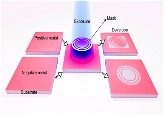
Figure 18.
(Photo- and e-beam) lithography process using positive and negative resists. Adapted from [84].
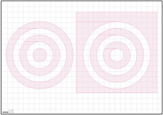
Figure 19.
GDS drawings of patterns (digital mask). Non-inverted (left) vs. inverted versions (right). The patterned area is irradiated during (photo- or e-beam) lithography. GDS: Graphic Design System.
Sometimes, for short-term experiments, such as experimental validation of the theoretical (DOE) model, only a patterned photoresist itself can be sufficient without further processing; only the thickness and refractive index of the photoresist need to be known [84,85,86]. In previously mentioned articles, the thickness of the photoresist (AR-P 3510T, Allresist, Strausberg, Germany) used was estimated to be up to 2.5 µm, and the refractive index was 1.6 according to ellipsometry.
To complete the photolithography process and make DOEs more durable over time, postprocessing, such as metallization with etching, is usually necessary. The lift-off process after metallization is an alternative for removing excess metals; it is simple and does not require subsequent wet or dry etching, as shown in Figure 20. The exposure of the resist must be optimized to avoid an overcut resist profile, and metallization should be carried out under high vacuum as much as possible. This ensures that the metal does not cover the walls of the irradiated and developed resist; otherwise, the lift-off will not work. The disadvantage of this method is that after lift-off patterning, unwanted curvatures may occur at the edges of the line (“rabbit ears”). To avoid this, another option is to use multilayer resists to create T-shaped profiles [89] DOEs with Ti/Au (6/100 nm) metal layers obtained via the lift-off method were used for analysis in [84,85,86]. Compared with DOEs fabricated by photolithography–metallization–lift-off and direct-writing femtosecond laser methods, the edge quality is well defined by photolithography. However, the optical results of DOEs fabricated via the ablation method are even better. The higher height profiles of the structures that are easier to achieve with the laser probably play a major role [9].
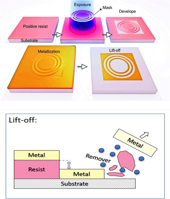
Figure 20.
Lithography with metallization and lift-off post-processes. Inset: schematic view of the lift-off process. Note that the metal layer must be thinner than the (photo- or e-beam) resist; otherwise, the remover cannot reach the resist to complete the process.
Complex 2.5-dimensional structures are also possible in (photo)lithography. In modern systems, patterns are drawn in grayscale (bitmap format) instead of using the physical grayscale photomask. Owing to the shades of gray tone design, the micro-mirrors (DMD®) travel rapidly between the ON and OFF stages, and the ratio of ON to OFF time determines the shade produced, which allows the creation of a stepped profile on the photoresist directly and very quickly. In short, this means that the photoresist is not fully irradiated but rather has various UV light intensities. Owing to the resolution demand in lithography, the focal lengths are very short. The field without x/y stage movement is restricted to several mm to minimize distortion and increase accuracy. For patterning of larger areas, they need to be subdivided into multiple fields, which are then stitched together using x-y stage movement. These stripe stitches are invisible in binary structures but become visible in deep areas (i.e., where the difference in photoresist thicknesses is large), especially when grayscale lithography is used. For stitching optimization, several functions can be used. For example, reducing the energy at the edges of stripes (mostly used for laser diode systems) or using N-fold overlapping of stripes, where the stripe shift is equal to the stripe width divided by a factor of N (mostly used for UV-LED DMD® systems). Grayscale lithography with subsequent reactive ion etching (RIE) allows 2.5-dimensional designs to be transferred into a substrate. In addition, taking advantage of photoresist reflow, it is also possible to create smooth 2.5-dimensional surface profiles. This is usually achieved by post-baking after the resist development process [90]. Another approach involves molding and replicating techniques or covering grayscale (photo)resist patterns with metal layers. In recent years, there have been studies on employing metasurface-based coded aperture masks for CAI and IDH [8,91,92].
8. Discussion
The recent developments and research directions in CAI techniques in the framework of incoherent holography have been thoroughly reviewed and discussed. The review starts with a brief overview of contemporary milestones in CAI techniques, i.e., FINCH, COACH, and I-COACH, followed by their subsequent developments, such as multidimensional imaging, associated computational algorithms, and image optimization techniques. In particular, we emphasized the significant developments made during the past two years, from 2022 to 2024, in CAI, i.e., recording and reconstruction methods, CM engineering techniques, advanced manufacturing methods for DOE fabrication, and multidimensional imaging applications. The emerging trends in CAI, as well as associated challenges and future prospects, are discussed further. Each section presents a comprehensive description, underlying principles, potential applications, and challenges encountered.
In CAI, although object information can be successfully reconstructed, the image quality typically does not match that of conventional direct imaging. Advancements in reconstruction algorithms—particularly those leveraging deep learning and computational optimization—are essential to expand CAI’s applicability across domains traditionally dominated by direct imaging. Another significant challenge lies in implementing CAI in photon-limited applications, such as astronomy and microscopy. These fields often depend on direct imaging techniques, as they require the collection of scarce photons at a single point to exceed the sensitivity threshold of image sensors. Overcoming these limitations is critical for extending CAI to such high-sensitivity domains.
Despite the aforementioned challenges, we are confident that CAI will continue to evolve into a more advanced and versatile imaging technology in the years ahead. With the rapid progress in deep learning and computational techniques, CAI is poised to integrate such methods to achieve enhanced imaging performance and robustness. One promising direction is the expansion of imaging dimensionality. Building on the progression from 3D in 2017 to 6D in 2024, further increases in dimensionality appear not only feasible but also likely. However, a trade-off is likely possible between the dimensionality and the imaging parameters, such as sensor resolution, computation efficiency, data sparsity.
Another key avenue is the development of CAI-based instrumentation, which will necessitate parallel advancements in supporting industries, particularly in precision optics and advanced manufacturing technologies. We believe that this review will serve as a valuable resource for future developments in CAI technologies.
9. Summary
The imaging systems discussed in this review are the latest examples of a scientific tradition spanning over two centuries of optical interferometry and diffraction. The interferometers of the 19th century and the first half of the 20th century combined two beams to create wave interference, but none of the beams carried any image [93]. Therefore, the interference pattern could not be applied for imaging. These circumstances changed in 1948 with the invention of the groundbreaking hologram by Gabor [94]. In early holograms, one of the beams carried a wavefront that diffracted from the observed object. However, Gabor’s concept of object and reference beams cannot work out for spatially incoherent light. The solution involves the principle of self-interference, in which each of the interfering beams carries two different images of the same object [95]. FINCH [55], with the SLM, enables the combination of self-interference with the phase-shifting procedure to record incoherent digital holograms in a single-channel setup. COACH [11] was introduced as an additional conceptual progress in which the image of the object is replicated and randomly distributed in the space of one of the interfering beams, whereas the other beam carries a single image as before. While the evolution of 3D holographic recorders became increasingly complicated, the I-COACH [13] appeared surprising in 2017, with the demonstrated claim that two-beam interference is not needed at all, at least not for multidimensional imaging. For other applications of quantitative phase imaging [96], synthetic aperture [49], and some techniques of super-resolution [97], two-beam interference still plays an important role.
The appearance of coded aperture imaging without two-wave interference has raised the issue of similarity between the new I-COACH and the older CAI [4,5], and this review provides a good opportunity to discuss the differences between the two technologies. CAI was invented as a generalization of the pinhole camera by using a mask with multiple pinholes instead of the single pinhole of the pinhole camera. As such, CAI is based on optical ray theory, and the effects of the more modern optical wave theory are not considered. Consequently, in CAI, the masks mostly modulate the transverse intensity distribution of light. Practically, this means that the power efficiency of CAI is lower than that of traditional imaging systems based on glassy lenses and curved mirrors because of the light absorption of the masks. Another drawback of CAI is the lack of longitudinal control of the images; thus, CAI systems are limited to 2D imaging. I-COACH, on the other hand, originated from holography, a concept that is based on optical wave theory, and the use of phase-only methods is a common practice in wave theory. Thus, power losses due to mask absorption are avoided. Moreover, the use of optical diffraction theory enables the design of 3D PSFs in I-COACH systems, and consequently, 3D imaging systems can be achieved [24,26,28,30]. Considering the polarization effects of optical waves enables us and other researchers to extend imaging systems to polarization detectors in addition to their 3D imaging properties [47,69].
The tale of I-COACH and modern CAI in the last decade is a classic example of how the development of one technology, the 3D structured light in this case, can trigger the development of other nonrelated technologies, such as the imaging systems in this example [14]. Most likely, the tale has not ended, and several new coded aperture imaging systems will probably appear in the coming years [98].
Author Contributions
Conceptualization, V.T. and V.A.; writing—original draft, V.T., S.G., T.K., F.G.A., A.P.I.X., N.J., J.R. and V.A.; writing—review and editing, V.T. and V.A.; supervision, V.A., J.R., K.K., A.T. and S.J.; funding acquisition, V.A., J.R. and S.J. All authors have read and agreed to the published version of the manuscript.
Funding
This research was funded by European Union’s Horizon 2020 research and innovation programme, Grant Agreement No. 857627 (CIPHR). This work was partly supported by the European Regional Development Fund under Grant 1.1.1.5/19/A/003; the Israel Innovation Authority (79555, MAGNET); Discovery Grant DP240103231 from the Australian Research Council; and the NAMUR+ core facility funded by the Estonian Research Council (TT 13).
Data Availability Statement
No new data were created or analyzed in this study. Data sharing is not applicable to this article.
Conflicts of Interest
The authors declare no conflicts of interest.
Abbreviations
The following abbreviations are used in this manuscript:
| CAI | Coded aperture imaging |
| DH | Digital holography |
| IDH | Incoherent digital holography |
| SLM | Spatial light modulator |
| PSF | Point spread function |
| COACH | Coded aperture correlation holography |
| I-COACH | Interferenceless coded aperture correlation holography |
| LI-COACH | Lensless interferenceless coded aperture correlation holography |
| SCS-I-COACH | Single camera shot interferenceless coded aperture correlation holography |
| SNR | Signal-to-noise ratio |
| FoV | Field of view |
| FINCH | Fresnel incoherent correlation holography |
| NLR | Non-linear reconstruction |
| LRA | Lucy–Richardson algorithm |
| LRRA | Lucy–Richardson–Rosen algorithm |
| INDIA | Incoherent non-linear reconstruction with an iterative algorithm |
| MF | Matched filter |
| PoF | Phase-only filter |
| NLR-LRA | Non-linear Lucy–Richardson algorithm |
| INCHIS | Incoherent hybrid imaging system |
| PEGASASS | Post-ensemble generation with airy beams for spatial and spectral switching |
| SCOPE | Super-resolution correlating optical endoscopy |
| DOE | Diffractive optical element |
| FVI | Full-view images |
| CM | Coded masks |
| LSI | Limited support images |
| MTF | Modulation transfer function |
| TAP-GSA | Transport of amplitude into phase based on Gerchberg–Saxton algorithm |
| CPSFE | Computational point spread function engineering |
| NA | Numerical aperture |
| TPP-SLM | Two polarization-sensitive phase-only spatial light modulator |
| QRDL | Quasi-random diffractive lens |
| OID | Object intensity distribution |
| CPM | Cubic phase mask |
| S-PSF | Synthetic point spread function |
| LAM | Lens array mask |
| ORI | Object response intensity |
| FWHM | Full-width half maximum |
| CAM | Combined aperture mask |
| OV | Optical vortices |
| VB | Vortex beams |
| OAM | Orbital angular momentum |
| SPP | Spiral phase plate |
| DMD | Digital micro-mirror device |
| RIE | Reactive ion etching |
| SMART | Synthetic marginal aperture with revolving telescopes |
| PAIS | Partial aperture imaging system |
References
- Rosen, J.; Vijayakumar, A.; Kumar, M.; Rai, M.R.; Kelner, R.; Kashter, Y.; Bulbul, A.; Mukherjee, S. Recent Advances in Self-Interference Incoherent Digital Holography. Adv. Opt. Photonics 2019, 11, 1–66. [Google Scholar] [CrossRef]
- Euliss, G.W.; Athale, R.A.; Mait, J.N. Computational Imaging. Adv. Opt. Photonics 2018, 10, 409–483. [Google Scholar]
- Rosen, J.; Alford, S.; Allan, B.; Anand, V.; Arnon, S.; Arockiaraj, F.G.; Art, J.; Bai, B.; Balasubramaniam, G.M.; Birnbaum, T.; et al. Roadmap on Computational Methods in Optical Imaging and Holography [Invited]. Appl. Phys. B 2024, 130, 166. [Google Scholar] [PubMed]
- Ables, J.G. Fourier Transform Photography: A New Method for X-Ray Astronomy. Publ. Astron. Soc. Aust. 1968, 1, 172–173. [Google Scholar] [CrossRef]
- Dicke, R.H. Scatter-Hole Cameras for X-Rays and Gamma Rays. Astrophys. J. 1968, 153, L-101. [Google Scholar] [CrossRef]
- Goodman, J.W.; Lawrence, R.W. Digital Image Formation from Electronically Detected Holograms. Appl. Phys. Lett. 1967, 11, 77–79. [Google Scholar] [CrossRef]
- Tahara, T.; Zhang, Y.; Rosen, J.; Anand, V.; Cao, L.; Wu, J.; Koujin, T.; Matsuda, A.; Ishii, A.; Kozawa, Y.; et al. Roadmap of Incoherent Digital Holography. Appl. Phys. B Lasers Opt. 2022, 128, 193. [Google Scholar] [CrossRef]
- Rosen, J.; Alford, S.; Anand, V.; Art, J.; Bouchal, P.; Bouchal, Z.; Erdenebat, M.U.; Huang, L.; Ishii, A.; Juodkazis, S.; et al. Roadmap on Recent Progress in Finch Technology. J. Imaging 2021, 7, 197. [Google Scholar] [CrossRef]
- Han, M.; Smith, D.; Kahro, T.; Stonytė, D.; Kasikov, A.; Gailevičius, D.; Tiwari, V.; Xavier, A.P.I.; Gopinath, S.; Ng, S.H.; et al. Extending the Depth of Focus of an Infrared Microscope Using a Binary Axicon Fabricated on Barium Fluoride. Micromachines 2024, 15, 537. [Google Scholar] [CrossRef]
- Mu, H.; Smith, D.; Ng, S.H.; Anand, V.; Le, N.H.A.; Dharmavarapu, R.; Khajehsaeidimahabadi, Z.; Richardson, R.T.; Ruther, P.; Stoddart, P.R.; et al. Fraxicon for Optical Applications with Aperture ∼1 Mm: Characterisation Study. Nanomaterials 2024, 14, 287. [Google Scholar] [CrossRef]
- Vijayakumar, A.; Kashter, Y.; Kelner, R.; Rosen, J. Coded Aperture Correlation Holography—A New Type of Incoherent Digital Holograms. Opt. Express 2016, 24, 12430–12441. [Google Scholar] [CrossRef] [PubMed]
- Vijayakumar, A.; Kashter, Y.; Kelner, R.; Rosen, J. Coded Aperture Correlation Holography System with Improved Performance [Invited]. Appl. Opt. 2017, 56, F67–F77. [Google Scholar] [CrossRef]
- Vijayakumar, A.; Rosen, J. Interferenceless Coded Aperture Correlation Holography—A New Technique for Recording Incoherent Digital Holograms without Two-Wave Interference. Opt. Express 2017, 25, 13883–13896. [Google Scholar] [CrossRef]
- Rosen, J.; Anand, V. Optical Imaging Using Coded Aperture Correlation Holography (COACH) with PSF of Spatial-Structured Longitudinal Light Beams—A Study Review. Photonics 2024, 11, 115. [Google Scholar] [CrossRef]
- Kumar, M.; Vijayakumar, A.; Rosen, J. Incoherent Digital Holograms Acquired by Interferenceless Coded Aperture Correlation Holography System without Refractive Lenses E. Sci. Rep. 2017, 7, 11555. [Google Scholar] [CrossRef]
- Zalevsky, Z.; Dorsch, R.G.; Mendlovic, D. Gerchberg–Saxton Algorithm Applied in the Fractional Fourier or the Fresnel Domain. Opt. Lett. 1996, 21, 842–844. [Google Scholar] [CrossRef]
- Kumar, M.; Anand, V.; Rosen, J. Interferenceless Incoherent Digital Holography with Binary Coded Apertures Optimized Using Direct Binary Search. Opt. Lasers Eng. 2023, 160, 107306. [Google Scholar] [CrossRef]
- Wang, J.; Zhao, Y. Lensless Multispectral Camera Based on a Coded Aperture Array. Sensors 2021, 21, 7757. [Google Scholar] [CrossRef]
- Antipa, N.; Kuo, G.; Heckel, R.; Mildenhall, B.; Bostan, E.; Ng, R.; Waller, L. DiffuserCam: Lensless Single-Exposure 3D Imaging. Optica 2018, 5, 1–9. [Google Scholar] [CrossRef]
- Singh, A.K.; Pedrini, G.; Takeda, M.; Osten, W. Scatter-Plate Microscope for Lensless Microscopy with Diffraction Limited Resolution. Sci. Rep. 2017, 7, 10687. [Google Scholar] [CrossRef]
- Rai, M.R.; Vijayakumar, A.; Rosen, J. Single Camera Shot Interferenceless Coded Aperture Correlation Holography. Opt. Lett. 2017, 42, 3992–3995. [Google Scholar]
- Rai, M.R.; Vijayakumar, A.; Ogura, Y.; Rosen, J. Resolution Enhancement in Nonlinear Interferenceless COACH with Point Response of Subdiffraction Limit Patterns. Opt. Express 2019, 27, 391–403. [Google Scholar] [CrossRef] [PubMed]
- Rai, M.R.; Rosen, J. Noise Suppression by Controlling the Sparsity of the Point Spread Function in Interferenceless Coded Aperture Correlation Holography (I-COACH). Opt. Express 2019, 27, 24311–24323. [Google Scholar] [CrossRef]
- Rai, M.R.; Rosen, J. Depth-of-Field Engineering in Coded Aperture Imaging. Opt. Express 2021, 29, 1634–1648. [Google Scholar] [CrossRef]
- Anand, V. Tuning Axial Resolution Independent of Lateral Resolution in a Computational Imaging System Using Bessel Speckles. Micromachines 2022, 13, 1347. [Google Scholar] [CrossRef]
- Kumar, R.; Anand, V.; Rosen, J. 3D Single Shot Lensless Incoherent Optical Imaging Using Coded Phase Aperture System with Point Response of Scattered Airy Beams. Sci. Rep. 2023, 13, 2996. [Google Scholar] [CrossRef]
- Gopinath, S.; Rajeswary, A.S.J.F.; Anand, V. Sculpting Axial Characteristics of Incoherent Imagers by Hybridization Methods. Opt. Lasers Eng. 2024, 172, 107837. [Google Scholar] [CrossRef]
- Gopinath, S.; Anand, V. Post-Ensemble Generation with Airy Beams for Spatial and Spectral Switching in Incoherent Imaging. Opt. Lett. 2024, 49, 3247–3250. [Google Scholar] [CrossRef]
- Bleahu, A.; Gopinath, S.; Kahro, T.; Angamuthu, P.P.; John Francis Rajeswary, A.S.; Prabhakar, S.; Kumar, R.; Salla, G.R.; Singh, R.P.; Kukli, K.; et al. 3D Incoherent Imaging Using an Ensemble of Sparse Self-Rotating Beams. Opt. Express 2023, 31, 26120–26134. [Google Scholar] [CrossRef]
- Wang, Y.; Yang, J.; Lu, X.; Zhang, W.; Wang, H.; Zhong, L.; Rosen, J.; Di, J.; Yang, L.; Huang, T. Accelerating Quad Airy Beams-Based Point Response for Interferenceless Coded Aperture Correlation Holography. Opt. Lett. 2024, 49, 4429–4432. [Google Scholar]
- Horner, J.L.; Gianino, P.D. Phase-Only Matched Filtering. Appl. Opt. 1984, 23, 812–816. [Google Scholar] [CrossRef] [PubMed]
- Rai, M.R.; Vijayakumar, A.; Rosen, J. Non-Linear Adaptive Three-Dimensional Imaging with Interferenceless Coded Aperture Correlation Holography (I-COACH). Opt. Express 2018, 26, 18143–18154. [Google Scholar] [CrossRef]
- Richardson, W.H. Bayesian-Based Iterative Method of Image Restoration. J. Opt. Soc. Am. 1972, 62, 55–59. [Google Scholar] [CrossRef]
- Lucy, L.B. An Iterative Technique for the Rectification of Observed Distributions. Astron. J. 1974, 79, 745. [Google Scholar] [CrossRef]
- Dhawan, A.P.; Rangayyan, R.M.; Gordon, R. Image Restoration by Wiener Deconvolution in Limited-View Computed Tomography. Appl. Opt. 1985, 24, 4013–4020. [Google Scholar] [CrossRef]
- Liu, C.; Zia, A.; Wan, Y. Interferenceless Coded Aperture Correlation Holography (I-COACH) Adaptive Compression Imaging. In Proceedings of the Eleventh International Conference on Information Optics and Photonics (CIOP), Xi’an, China, 6–9 August 2019; Volume 11209. [Google Scholar]
- Wan, Y.; Liu, C.; Ma, T.; Qin, Y.; Lv, S. Incoherent Coded Aperture Correlation Holographic Imaging with Fast Adaptive and Noise-Suppressed Reconstruction. Opt. Express 2021, 29, 8064–8075. [Google Scholar] [CrossRef]
- Ma, T.; Liu, C.; Wan, Y. Interferenceless Coded Aperture Correlation Holography with Enhanced Reconstruction Image Quality by Employing an Optimization Coded Phase Mask. In Proceedings of the Holography, Diffractive Optics, and Applications XI, Nantong, China, 10–19 October 2021; Volume 11898. [Google Scholar]
- Liu, C.; Man, T.; Wan, Y. High-Quality Interferenceless Coded Aperture Correlation Holography with Optimized High SNR Holograms. Appl. Opt. 2022, 61, 661–668. [Google Scholar] [CrossRef]
- Zhang, M.; Wan, Y.; Man, T.; Zhang, W.; Zhou, H. Non-Iterative Reconstruction of Interferenceless Coded Aperture Correlation Holography Enabled High Quality Three-Dimensional Imaging. Opt. Lasers Eng. 2024, 173, 107929. [Google Scholar] [CrossRef]
- Anand, V.; Han, M.; Maksimovic, J.; Ng, S.H.; Katkus, T.; Klein, A.; Bambery, K.; Tobin, M.J.; Vongsvivut, J.; Juodkazis, S. Single-Shot Mid-Infrared Incoherent Holography Using Lucy-Richardson-Rosen Algorithm. Opto-Electron. Sci. 2022, 1, 210006. [Google Scholar] [CrossRef]
- Rosen, J.; Anand, V. Incoherent Nonlinear Deconvolution Using an Iterative Algorithm for Recovering Limited-Support Images from Blurred Digital Photographs. Opt. Express 2024, 32, 1034–1046. [Google Scholar] [CrossRef]
- Xavier, A.P.I.; Kahro, T.; Gopinath, S.; Tiwari, V.; Smith, D.; Kasikov, A.; Piirsoo, H.M.; Ng, S.H.; Rajeswary, A.S.J.F.; Vongsvivut, J.; et al. Coded Aperture Imaging Using Non-Linear Lucy-Richardson Algorithm. Opt. Laser Technol. 2025, 183, 112300. [Google Scholar] [CrossRef]
- Anand, V.; Ng, S.H.; Maksimovic, J.; Linklater, D.; Katkus, T.; Ivanova, E.P.; Juodkazis, S. Single Shot Multispectral Multidimensional Imaging Using Chaotic Waves. Sci. Rep. 2020, 10, 13902. [Google Scholar] [CrossRef] [PubMed]
- Anand, V.; Ng, S.H.; Katkus, T.; Juodkazis, S. White Light Three-Dimensional Imaging Using a Quasi-Random Lens. Opt. Express 2021, 29, 15551–15563. [Google Scholar] [CrossRef] [PubMed]
- Smith, D.; Ng, S.H.; Han, M.; Katkus, T.; Anand, V.; Glazebrook, K.; Juodkazis, S. Imaging with Diffractive Axicons Rapidly Milled on Sapphire by Femtosecond Laser Ablation. Appl. Phys. B Lasers Opt. 2021, 127, 154. [Google Scholar] [CrossRef]
- Joshi, N.; Tiwari, V.; Kahro, T.; Xavier, A.P.I.; Tahara, T.; Kasikov, A.; Kukli, K.; Juodkazis, S.; Tamm, A.; Rosen, J.; et al. Interferenceless Coded Aperture Correlation Holography for Five-Dimensional Imaging of 3D Space, Spectrum and Polarization. J. Phys. Photonics 2025, 7, 25004. [Google Scholar] [CrossRef]
- Bulbul, A.; Vijayakumar, A.; Rosen, J. Partial Aperture Imaging by Systems with Annular Phase Coded Masks. Opt. Express 2017, 25, 33315–33329. [Google Scholar] [CrossRef]
- Bulbul, A.; Vijayakumar, A.; Rosen, J. Superresolution Far-Field Imaging by Coded Phase Reflectors Distributed Only along the Boundary of Synthetic Apertures. Optica 2018, 5, 1607–1616. [Google Scholar] [CrossRef]
- Rai, M.R.; Vijayakumar, A.; Rosen, J. Extending the Field of View by a Scattering Window in an I-COACH System. Opt. Lett. 2018, 43, 1043–1046. [Google Scholar] [CrossRef]
- Kashter, Y.; Vijayakumar, A.; Rosen, J. Resolving Images by Blurring: Superresolution Method with a Scattering Mask between the Observed Objects and the Hologram Recorder. Optica 2017, 4, 932–939. [Google Scholar] [CrossRef]
- Vijayakumar, A.; Kumar, M.; Rai, M.R.; Rosen, J. Coded Aperture Correlation Holography System for Recording Secured Digital Holograms of Incoherently Illuminated 3D Scenes. In Advanced Secure Optical Image Processing for Communications; IOP Publishing: Bristol, UK, 2018; Volume 4, pp. 1–19. ISBN 978-0-7503-1457-2. [Google Scholar]
- Ignatius Xavier, A.P.; Arockiaraj, F.G.; Gopinath, S.; John Francis Rajeswary, A.S.; Reddy, A.N.K.; Ganeev, R.A.; Singh, M.S.A.; Tania, S.D.M.; Anand, V. Single-Shot 3D Incoherent Imaging Using Deterministic and Random Optical Fields with Lucy–Richardson–Rosen Algorithm. Photonics 2023, 10, 987. [Google Scholar] [CrossRef]
- Rosen, J.; Brooker, G. Digital Spatially Incoherent Fresnel Holography. Opt. Lett. 2007, 32, 912–914. [Google Scholar] [CrossRef] [PubMed]
- Rosen, J.; Brooker, G. Non-Scanning Motionless Fluorescence Three-Dimensional Holographic Microscopy. Nat. Photonics 2008, 2, 190–195. [Google Scholar] [CrossRef]
- Katz, B.; Rosen, J.; Kelner, R.; Brooker, G. Enhanced Resolution and Throughput of Fresnel Incoherent Correlation Holography (FINCH) Using Dual Diffractive Lenses on a Spatial Light Modulator (SLM). Opt. Express 2012, 20, 9109–9121. [Google Scholar] [CrossRef]
- Rosen, J.; Siegel, N.; Brooker, G. Theoretical and experimental demonstration of resolution beyond the Rayleigh limit by FINCH fluorescence microscopic imaging. Opt. Express 2011, 19, 26249–26268. [Google Scholar] [CrossRef]
- Gustafsson, M.G. Surpassing the lateral resolution limit by a factor of two using structured illumination microscopy. J. Microsc. 2000, 198, 82–87. [Google Scholar] [CrossRef]
- Kashter, Y.; Vijayakumar, A.; Miyamoto, Y.; Rosen, J. Enhanced Super Resolution Using Fresnel Incoherent Correlation Holography with Structured Illumination. Opt. Lett. 2016, 41, 1558–1561. [Google Scholar] [CrossRef]
- Nobukawa, T.; Muroi, T.; Katano, Y.; Kinoshita, N.; Ishii, N. Single-Shot Phase-Shifting Incoherent Digital Holography with Multiplexed Checkerboard Phase Gratings. Opt. Lett. 2018, 43, 1698–1701. [Google Scholar] [CrossRef]
- Sakamaki, S.; Yoneda, N.; Nomura, T. Single-Shot in-Line Fresnel Incoherent Holography Using a Dual-Focus Checkerboard Lens. Appl. Opt. 2020, 59, 6612–6618. [Google Scholar] [CrossRef]
- Tahara, T.; Kanno, T.; Arai, Y.; Ozawa, T. Single-Shot Phase-Shifting Incoherent Digital Holography. J. Opt. 2017, 19, 065705. [Google Scholar] [CrossRef]
- Quan, X.; Matoba, O.; Awatsuji, Y. Single-shot incoherent digital holography using a dual-focusing lens with diffraction gratings. Opt. Lett. 2017, 42, 383–386. [Google Scholar] [CrossRef]
- Vijayakumar, A.; Katkus, T.; Lundgaard, S.; Linklater, D.P.; Ivanova, E.P.; Ng, S.H.; Juodkazis, S. Fresnel Incoherent Correlation Holography with Single Camera Shot. Opto-Electron. Adv. 2020, 3, 200004. [Google Scholar] [CrossRef]
- Arockiaraj, F.G.; Xavier, A.P.I.; Gopinath, S.; Rajeswary, A.S.J.F.; Juodkazis, S.; Anand, V. Optimizing the Temporal and Spatial Resolutions and Light Throughput of Fresnel Incoherent Correlation Holography in the Framework of Coded Aperture Imaging. J. Opt. 2024, 26, 035605. [Google Scholar] [CrossRef]
- Gopinath, S.; Bleahu, A.; Kahro, T.; John Francis Rajeswary, A.S.; Kumar, R.; Kukli, K.; Tamm, A.; Rosen, J.; Anand, V. Enhanced Design of Multiplexed Coded Masks for Fresnel Incoherent Correlation Holography. Sci. Rep. 2023, 13, 7390. [Google Scholar] [CrossRef]
- Sahoo, S.K.; Tang, D.; Dang, C. Single-Shot Multispectral Imaging with a Monochromatic Camera. Optica 2017, 4, 1209–1213. [Google Scholar] [CrossRef]
- Vijayakumar, A.; Rosen, J. Spectrum and Space Resolved 4D Imaging by Coded Aperture Correlation Holography (COACH) with Diffractive Objective Lens. Opt. Lett. 2017, 42, 947–950. [Google Scholar] [CrossRef]
- Treibitz, T.; Schechner, Y.Y. Active Polarization Descattering. IEEE Trans. Pattern Anal. Mach. Intell. 2009, 31, 385–399. [Google Scholar] [CrossRef]
- Wang, J.; Tan, X.; Qi, P.; Wu, C.; Huang, L.; Xu, X.; Huang, Z.; Zhu, L.; Zhang, Y.; Lin, X.; et al. Linear Polarization Holography. Opto-Electron. Sci. 2022, 1, 210009. [Google Scholar] [CrossRef]
- Zang, J.; Fan, F.; Liu, Y.; Wei, R.; Tan, X. Four-Channel Volume Holographic Recording with Linear Polarization Holography. Opt. Lett. 2019, 44, 4107–4110. [Google Scholar] [CrossRef]
- Tiwari, V.; Bisht, N.S. Extended Depth of Field of a Diffraction Limited Imaging System Using a Spatial Light Modulator Based Intensity Compensated Polarization Coded Aperture. Opt. Contin. 2023, 2, 1–8. [Google Scholar] [CrossRef]
- Tahara, T. Polarization-Filterless Polarization-Sensitive Polarization-Multiplexed Phase-Shifting Incoherent Digital Holography (P 4 IDH). Opt. Lett. 2023, 48, 3881–3884. [Google Scholar] [CrossRef]
- Tahara, T. Incoherent Digital Holography with Two Polarization-Sensitive Phase-Only Spatial Light Modulators and Reduced Number of Exposures. Appl. Opt. 2024, 63, B24–B31. [Google Scholar] [CrossRef] [PubMed]
- Gerchberg, R.W.; Saxton, W.O. A practical algorithm for the determination of phase from image and diffraction plane pictures. Optik 1972, 35, 235–246. [Google Scholar]
- De Groen, P.C. History of the Endoscope [Scanning Our Past]. Proc. IEEE 2017, 105, 1987–1995. [Google Scholar] [CrossRef]
- Ponsky, J.L.; Strong, A.T. A History of Flexible Gastrointestinal Endoscopy. Surg. Clin. N. Am. 2020, 100, 971–992. [Google Scholar] [CrossRef]
- Goetz, M.; Malek, N.P.; Kiesslich, R. Microscopic Imaging in Endoscopy: Endomicroscopy and Endocytoscopy. Nat. Rev. Gastroenterol. Hepatol. 2014, 11, 11–18. [Google Scholar] [CrossRef]
- Kiesslich, R.; Goetz, M.; Hoffman, A.; Galle, P.R. New Imaging Techniques and Opportunities in Endoscopy. Nat. Rev. Gastroenterol. Hepatol. 2011, 8, 547–553. [Google Scholar] [CrossRef]
- Turtaev, S.; Leite, I.T.; Čižmár, T. Multimode Fibres for Micro-Endoscopy. Optofluidics Microfluid. Nanofluidics 2016, 2, 31–35. [Google Scholar] [CrossRef]
- Wen, Z.; Dong, Z.; Deng, Q.; Pang, C.; Kaminski, C.F.; Xu, X.; Yan, H.; Wang, L.; Liu, S.; Tang, J.; et al. Single Multimode Fibre for in Vivo Light-Field-Encoded Endoscopic Imaging. Nat. Photonics 2023, 17, 679–687. [Google Scholar] [CrossRef]
- Dubey, N.; Rosen, J.; Gannot, I. High-Resolution Imaging System with an Annular Aperture of Coded Phase Masks for Endoscopic Applications. Opt. Express 2020, 28, 15122–15137. [Google Scholar] [CrossRef] [PubMed]
- Tamm, O.; Tiwari, V.; Gopinath, S.; Rajeswary, A.S.J.F.; Singh, S.A.; Rosen, J.; Anand, V. Super-Resolution Correlating Optical Endoscopy. IEEE Access 2024, 12, 76955–76962. [Google Scholar] [CrossRef]
- Tan, N.Y.J.; Zhang, X.; Neo, D.W.K.; Huang, R.; Liu, K.; Senthil Kumar, A. A Review of Recent Advances in Fabrication of Optical Fresnel Lenses. J. Manuf. Process. 2021, 71, 113–133. [Google Scholar] [CrossRef]
- Sohn, J.S.; Lee, M.B.; Kim, W.C.; Cho, E.H.; Kim, T.W.; Yoon, C.Y.; Park, N.C.; Park, Y.P. Design and Fabrication of Diffractive Optical Elements by Use of Gray-Scale Photolithography. Appl. Opt. 2005, 44, 506–511. [Google Scholar] [CrossRef]
- Zhou, P.; Xue, C.; Yang, C.; Liu, C.; Liu, X. Diffraction Efficiency Evaluation for Diamond Turning of Harmonic Diffractive Optical Elements. Appl. Opt. 2020, 59, 1537–1544. [Google Scholar] [CrossRef]
- Stonyte, D.; Jukna, V.; Lukosiunas, I.; Zakarauskas, P.; Huang, H.-H.; Katkus, T.; Zheng, N.; Le, N.H.A.; Juodkazis, S.; Juodkazis, S.; et al. Four-Level Diffractive Photon Sieves by Deep-UV Femtosecond Laser Ablation. Opt. Express 2024, 32, 43102–43117. [Google Scholar] [CrossRef]
- Watson, G.P.; Aksyuk, V.; Simon, M.E.; Tennant, D.M.; Cirelli, R.A.; Mansfield, W.M.; Pardo, F.; Lopez, D.O.; Bolle, C.A.; Papazian, A.R.; et al. Spatial Light Modulator for Maskless Optical Projection Lithography. J. Vac. Sci. Technol. B Microelectron. Nanom. Struct. Process. Meas. Phenom. 2006, 24, 2852–2856. [Google Scholar] [CrossRef]
- Elshenety, A.; Kucuk, M.M.; Yilmaz, M. High Thickness Material Lift-off Using Multi-Layer Photoresist. J. Micromechanics Microengineering 2025, 35, 025012. [Google Scholar] [CrossRef]
- Stilson, C.; Pal, R.; Coutu, R.A. Fabrication of 3D Surface Structures Using Grayscale Lithography. In Proceedings of the Micromachining and Microfabrication Process Technology XIX (SPIE), San Francisco, CA, USA, 4–6 February 2014; Volume 8973. [Google Scholar]
- Xia, H.; Chen, B.; Zhang, C.; Zhu, X.; Wang, C.; Zheng, Z. Joint optimization of coded aperture metasurface and residual self-attention network for snapshot full-Stokes imaging. Opt. Express 2024, 32, 29609–29619. [Google Scholar] [CrossRef]
- Colburn, S.; Zhan, A.; Majumdar, A. Metasurface optics for full-color computational imaging. Sci. Adv. 2018, 4, eaar2114. [Google Scholar] [CrossRef]
- Nolte, D.D. Interference: The History of Optical Interferometry and the Scientists Who Tamed Light; Oxford University Press: New York, NY, USA, 2023; ISBN 9780191965968. [Google Scholar]
- Gabor, D. A new microscopic principle. Nature 1948, 161, 777. [Google Scholar] [CrossRef]
- Cochran, G. New method of making Fresnel transforms with incoherent light. J. Opt. Soc. Am. 1966, 56, 1513–1517. [Google Scholar] [CrossRef]
- Hai, N.; Rosen, J. Coded aperture correlation holographic microscope for single-shot quantitative phase and amplitude imaging with extended field of view. Opt. Express 2020, 28, 27372–27386. [Google Scholar] [CrossRef]
- Bulbul, A.; Hai, N.; Rosen, J. Coded aperture correlation holography (COACH) with a superior lateral resolution of FINCH and axial resolution of conventional direct imaging systems. Opt. Express 2021, 29, 42106–42118. [Google Scholar] [CrossRef]
- Mait, J.N.; Athale, R.A.; Euliss, G.W. Two Decades of Computational Imaging: Still serving old wine in new bottles? In Imaging and Applied Optics, Optica Publishing Group; Optica Publishing Group: Washington, DC, USA, 2017; p. CM2B.1. [Google Scholar]
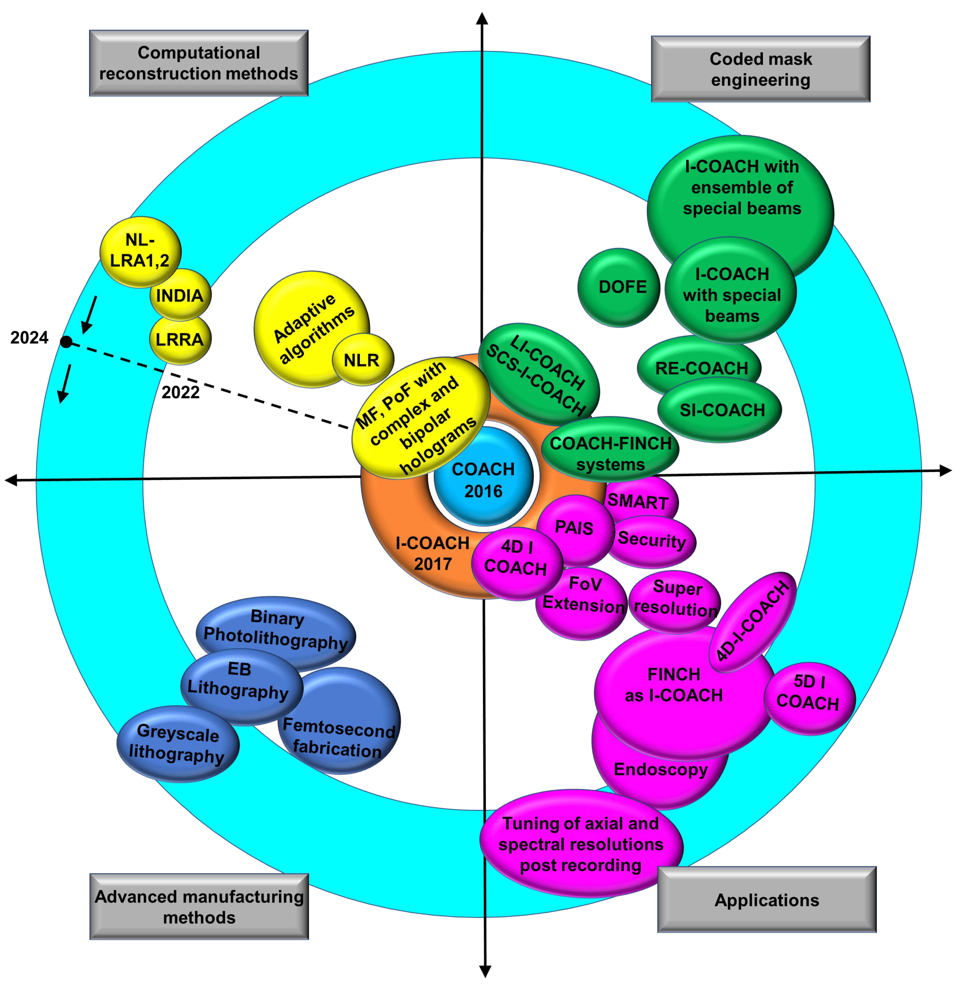
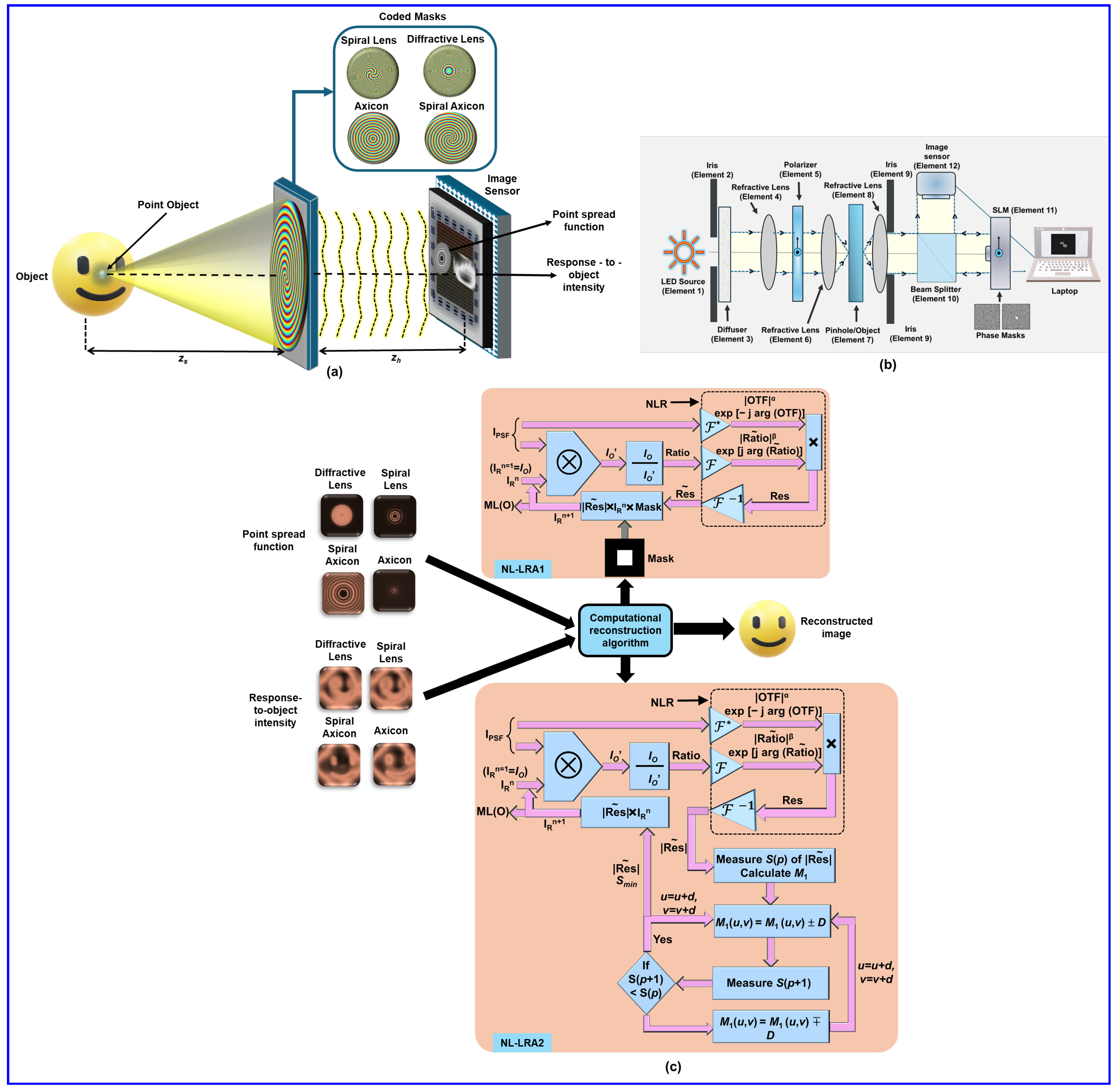
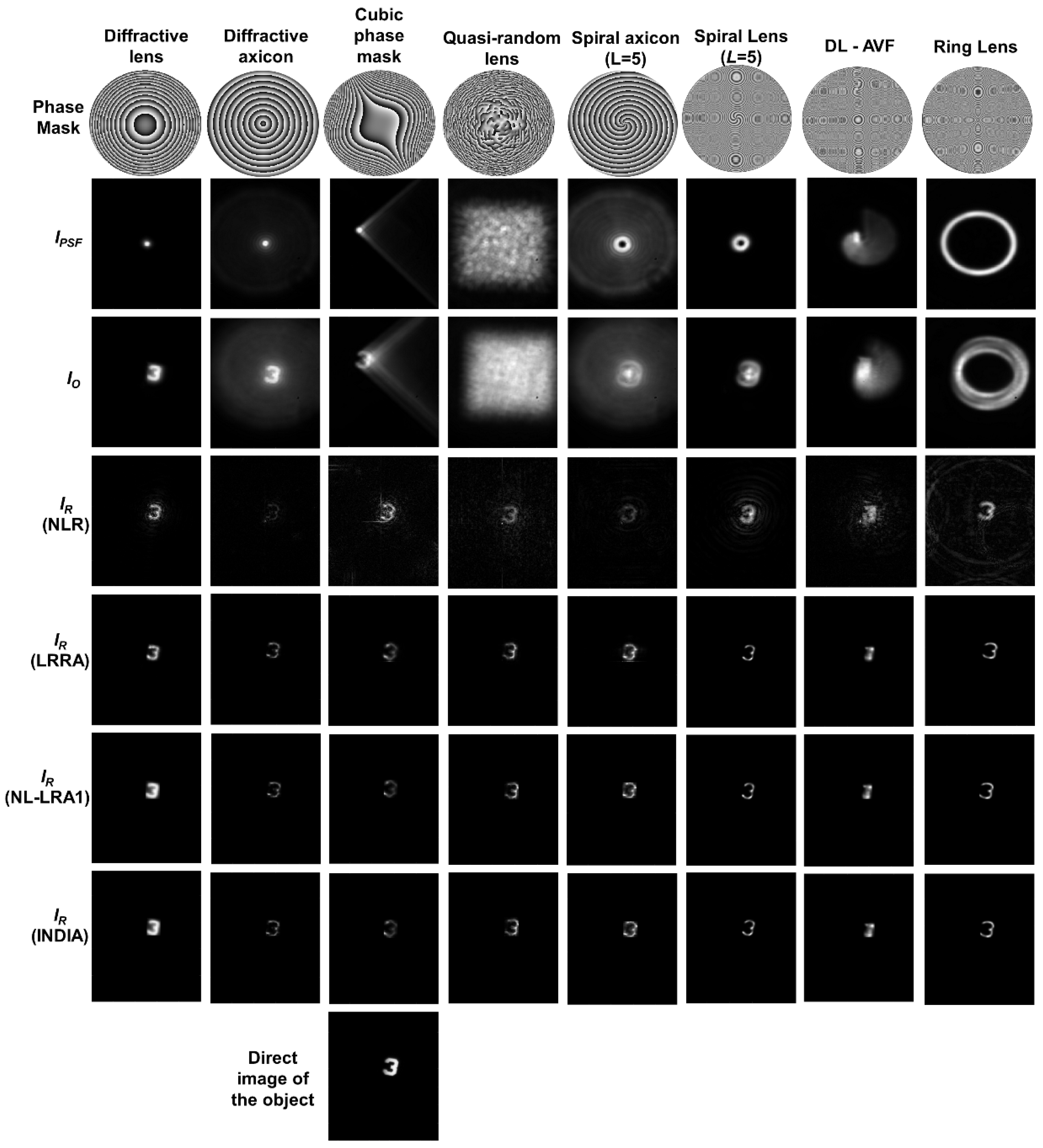
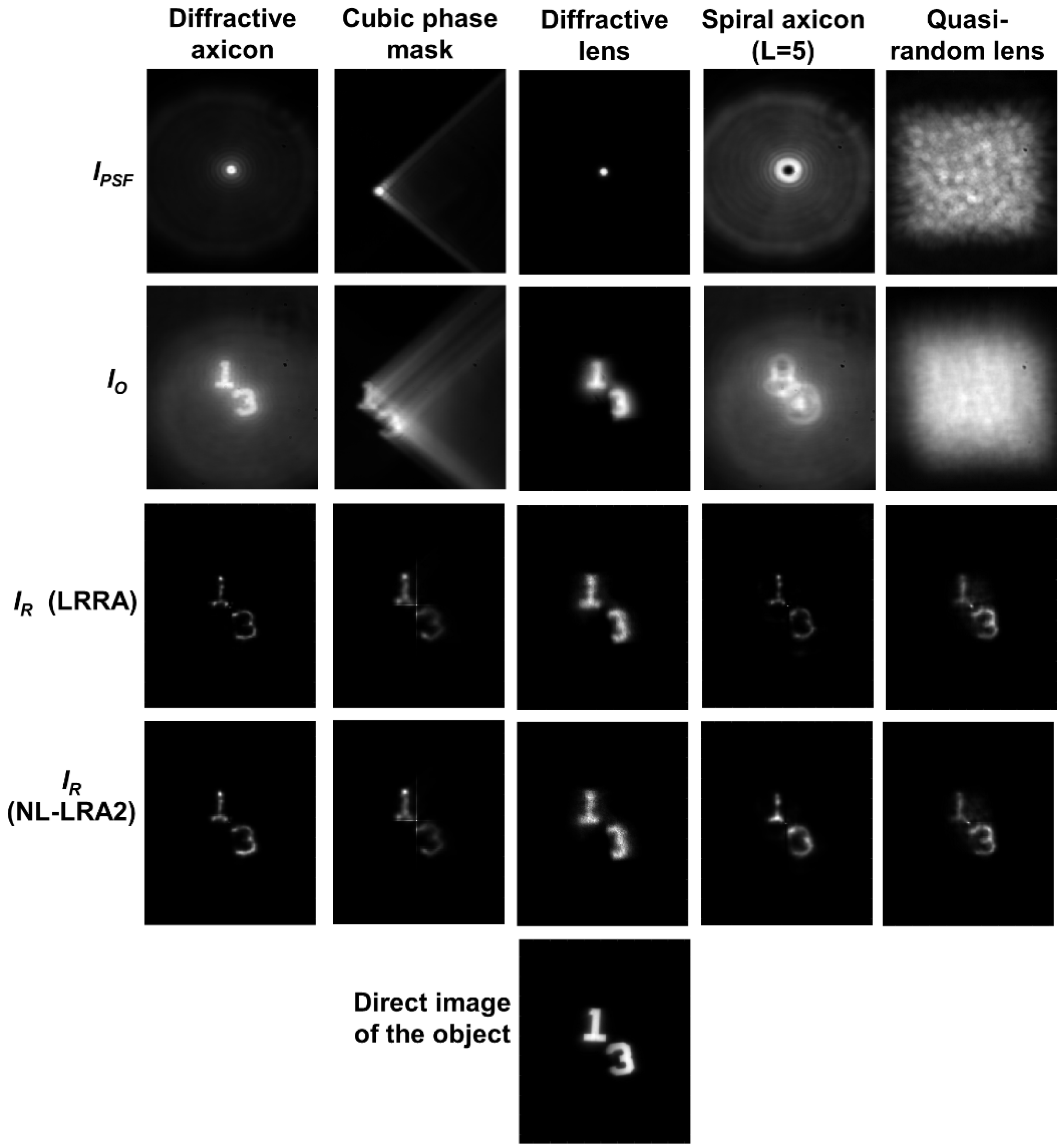

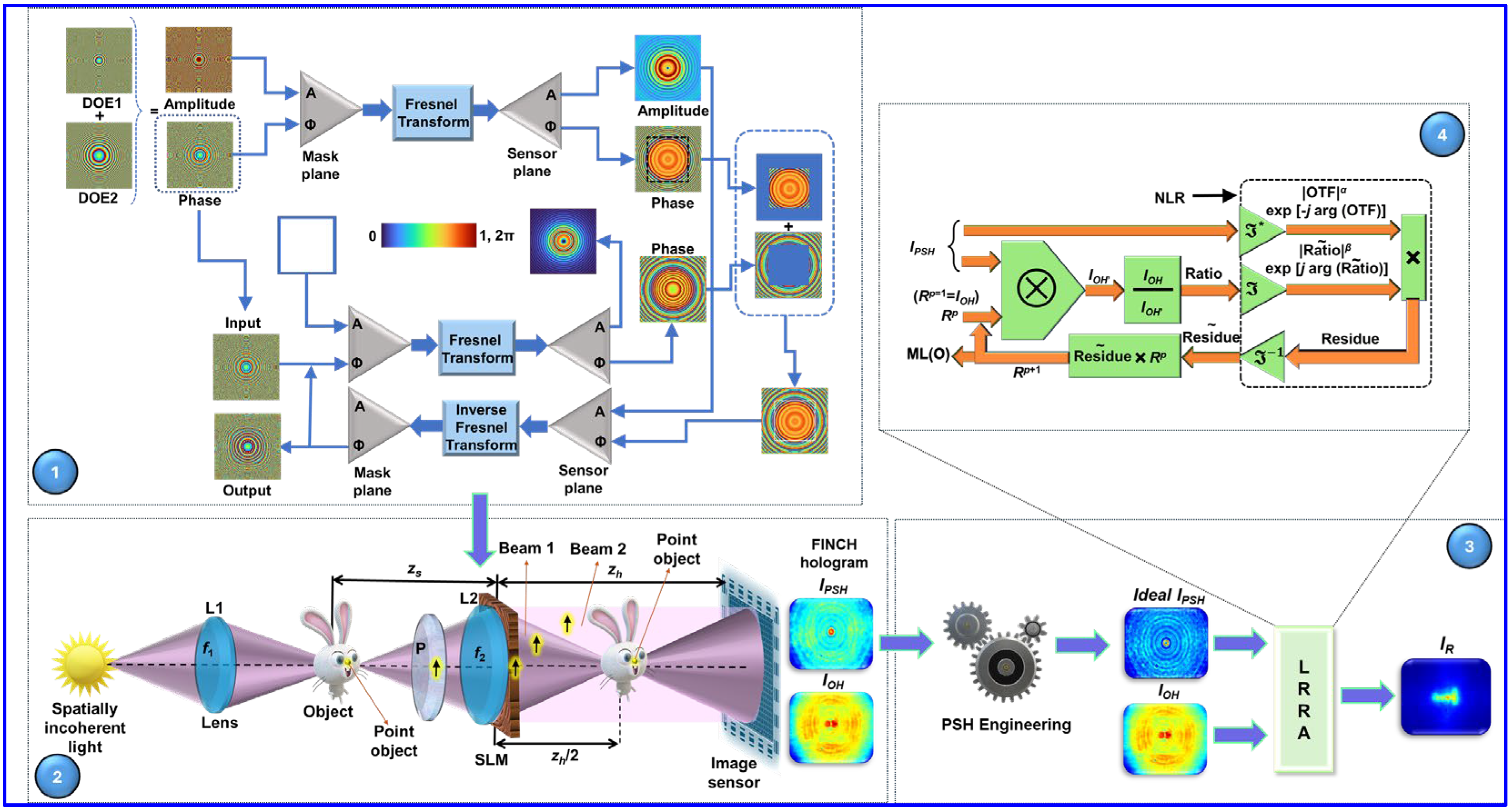
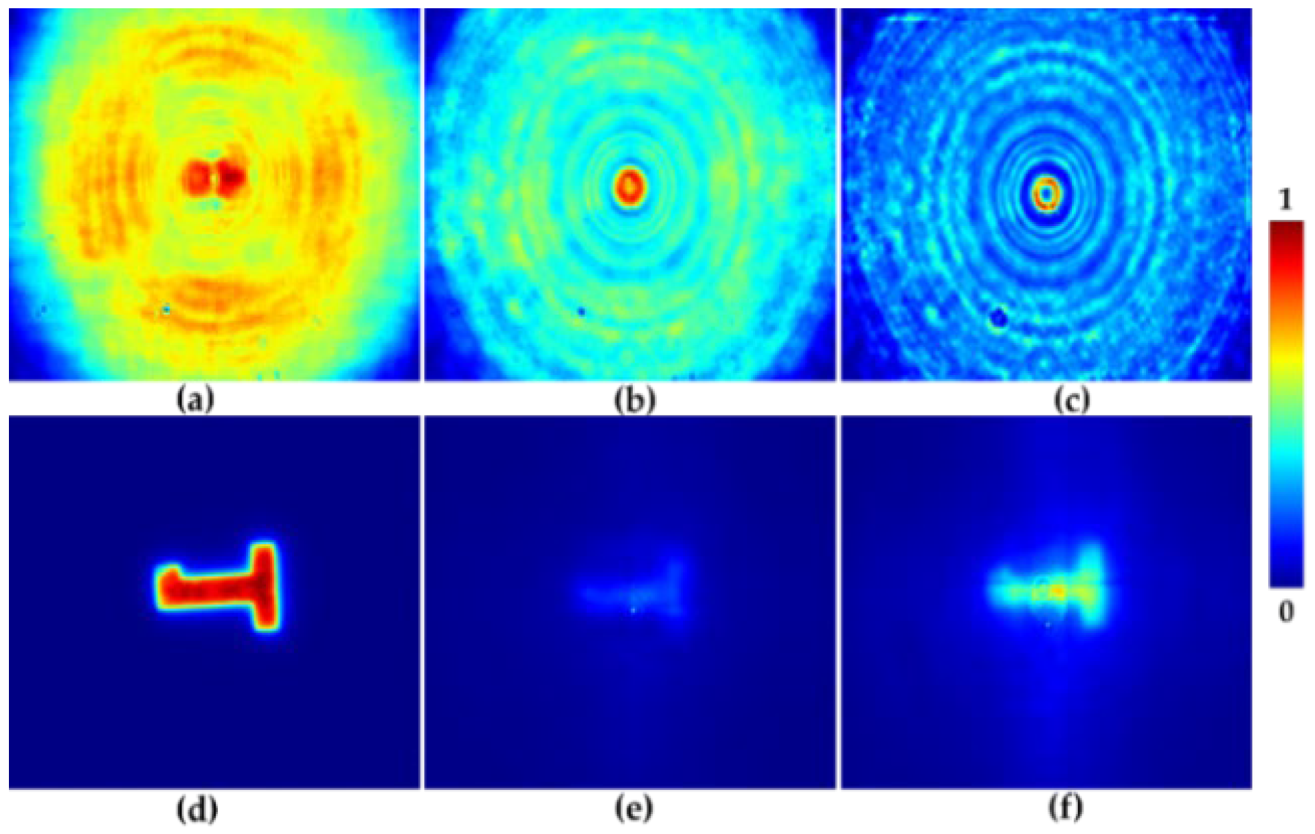
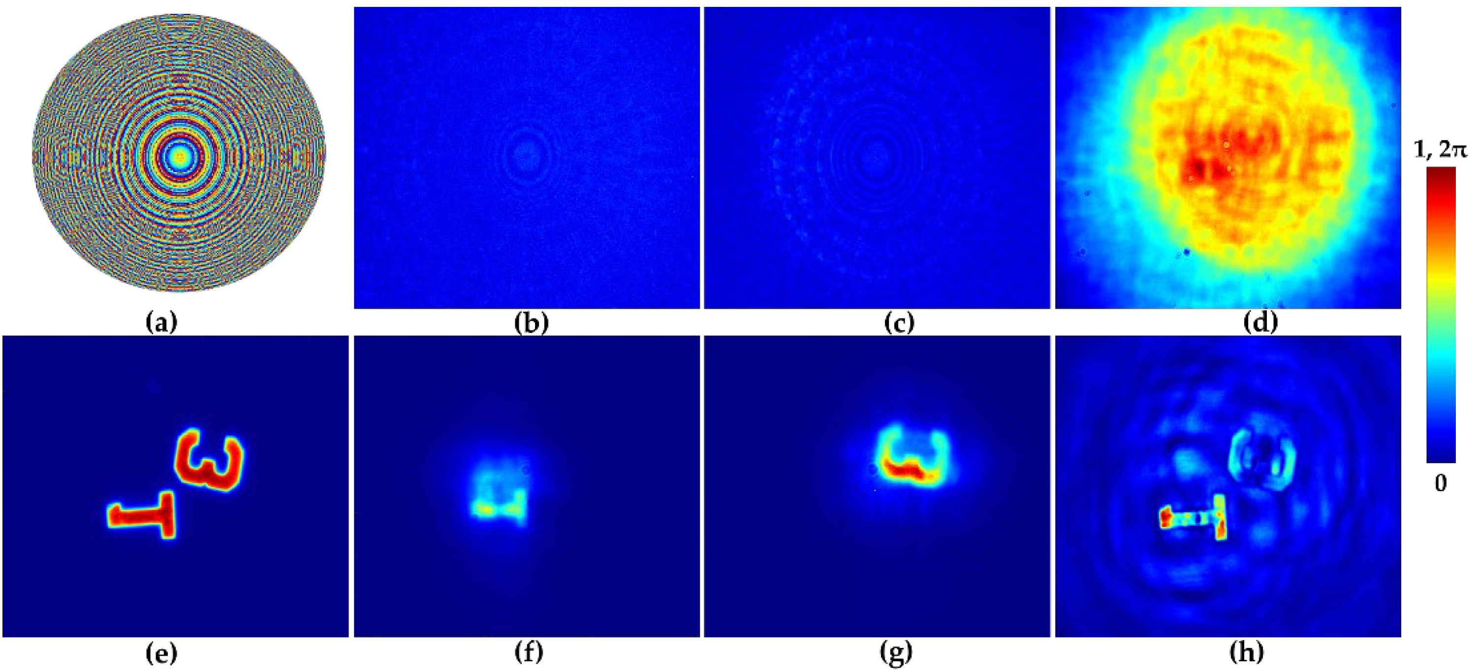
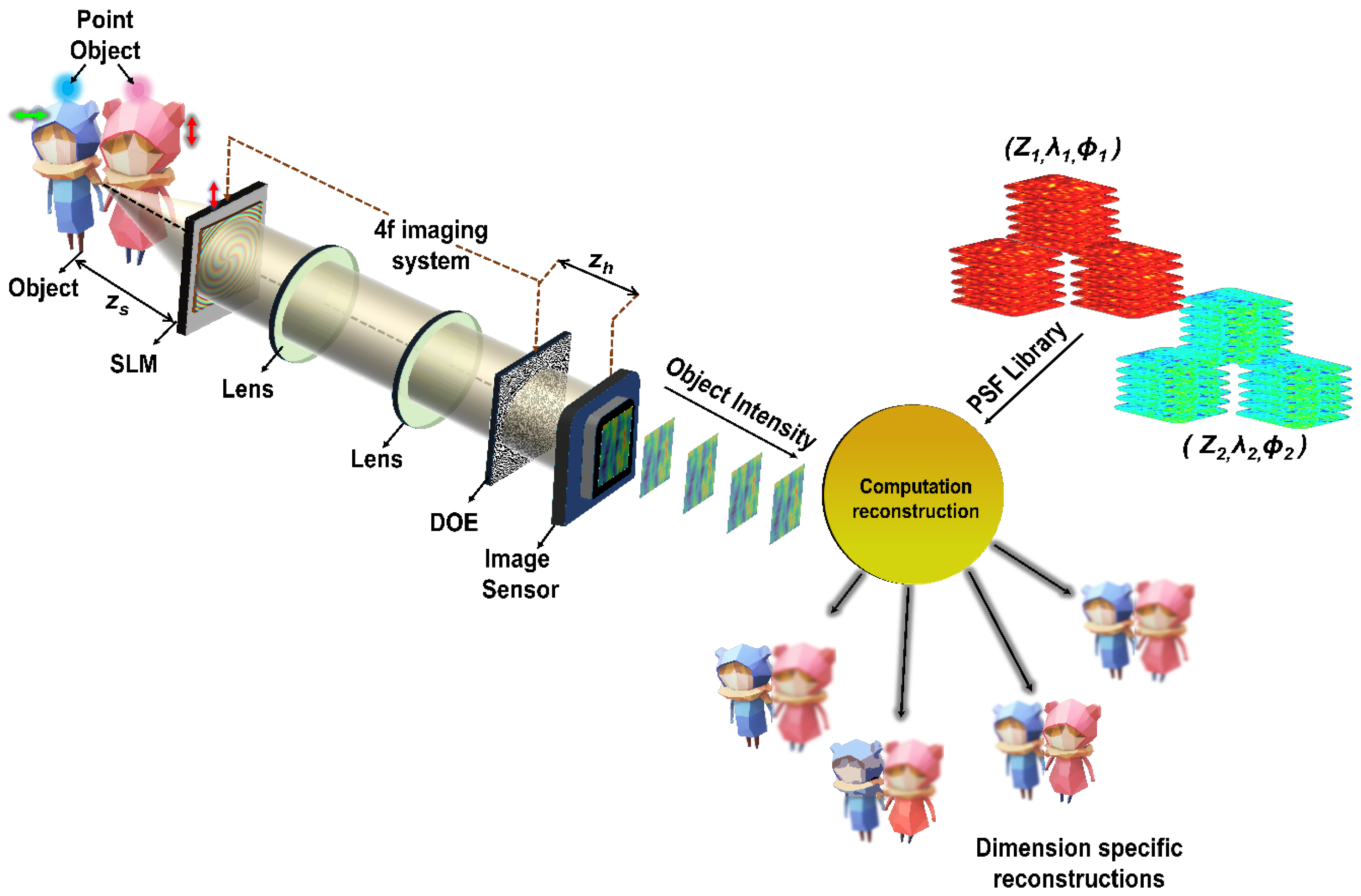


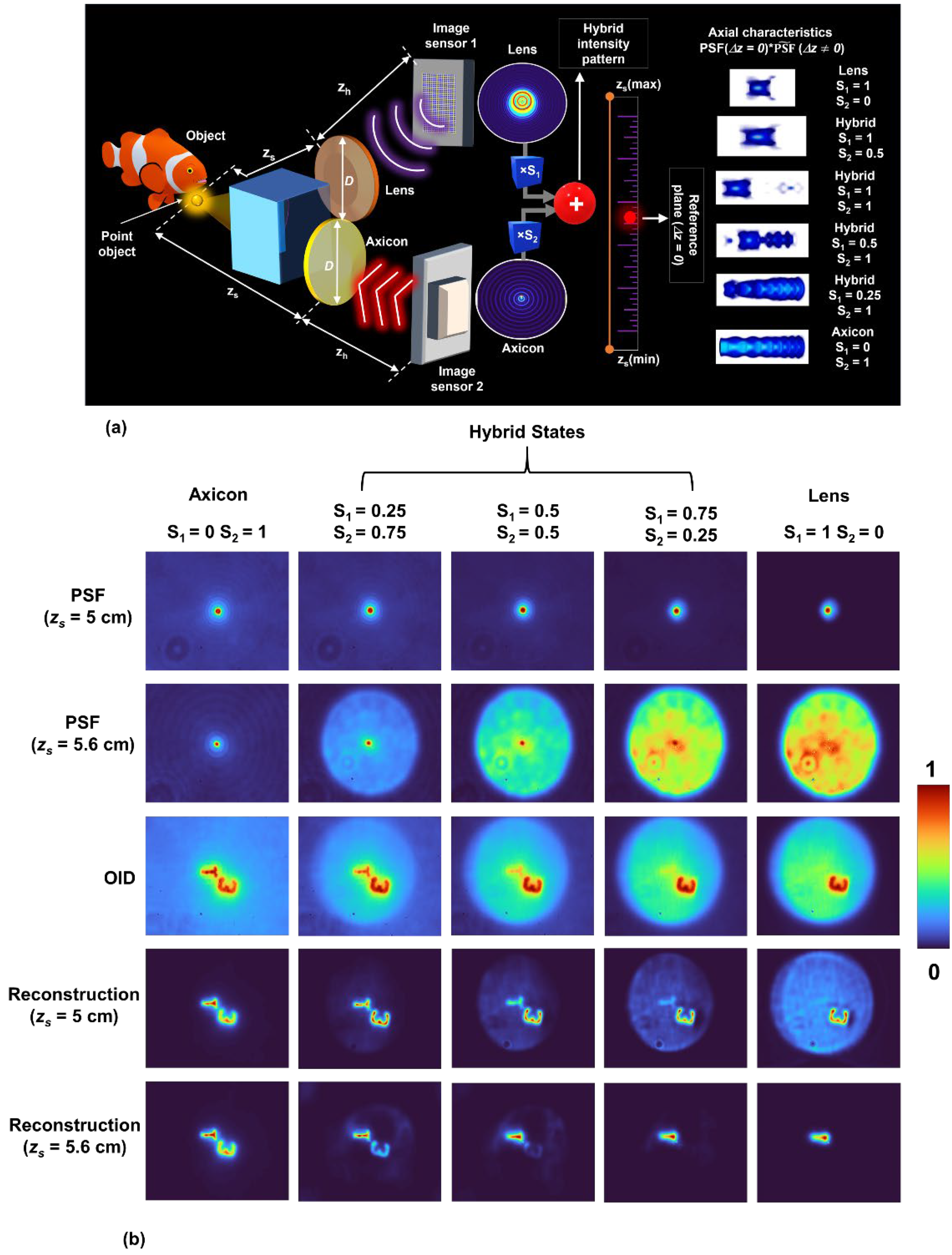
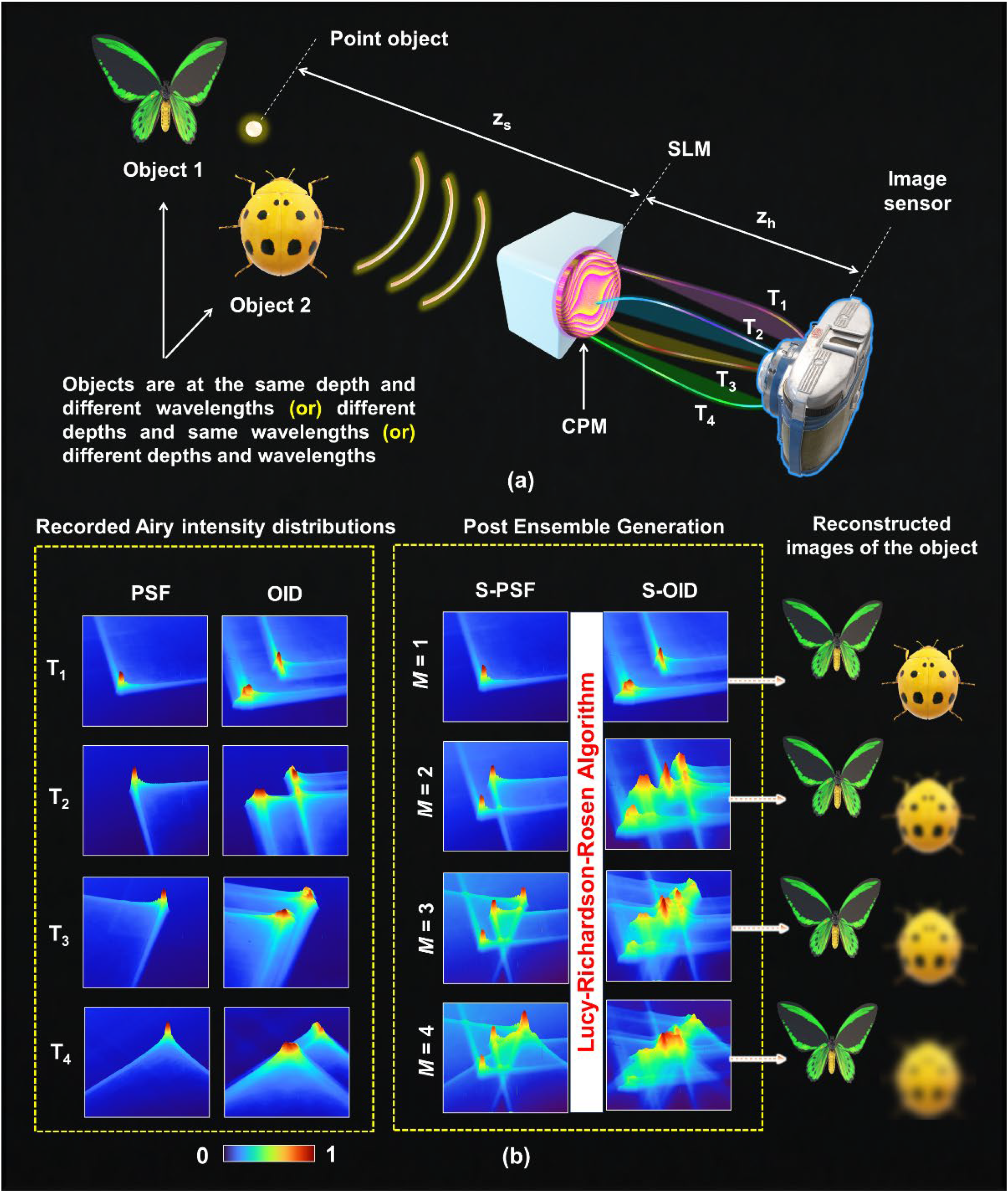
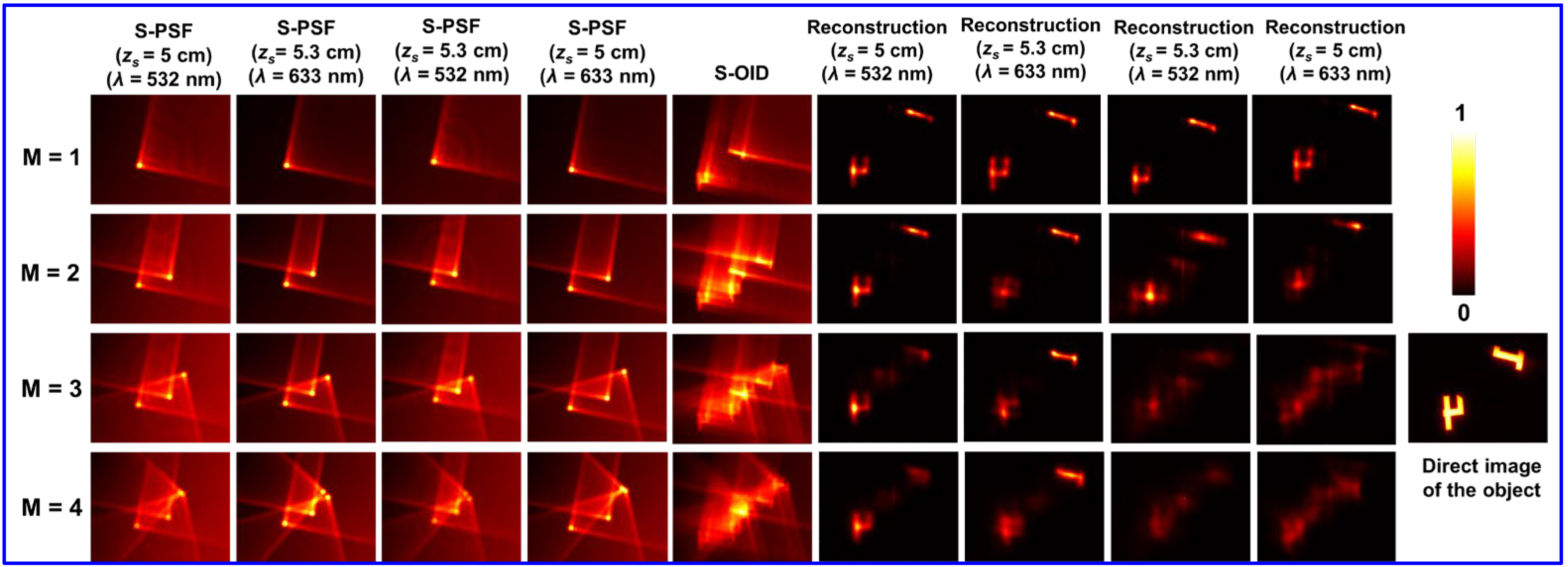

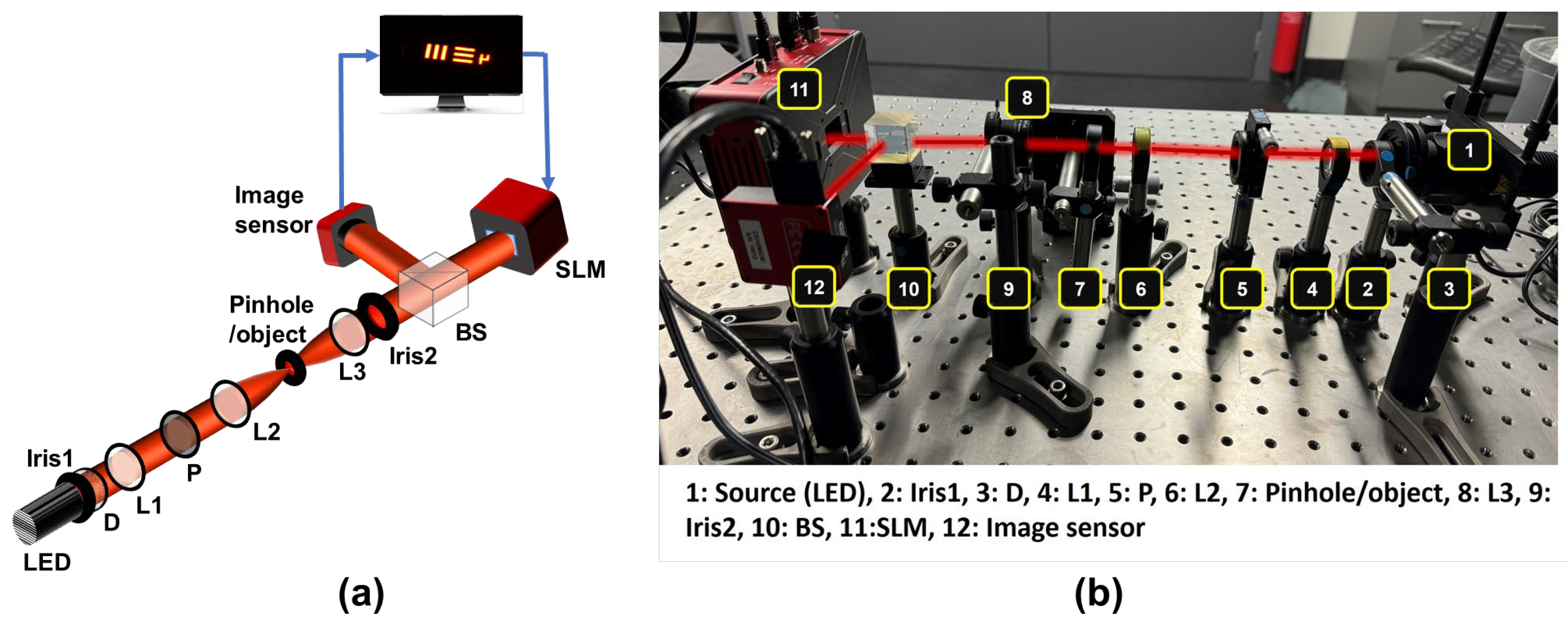
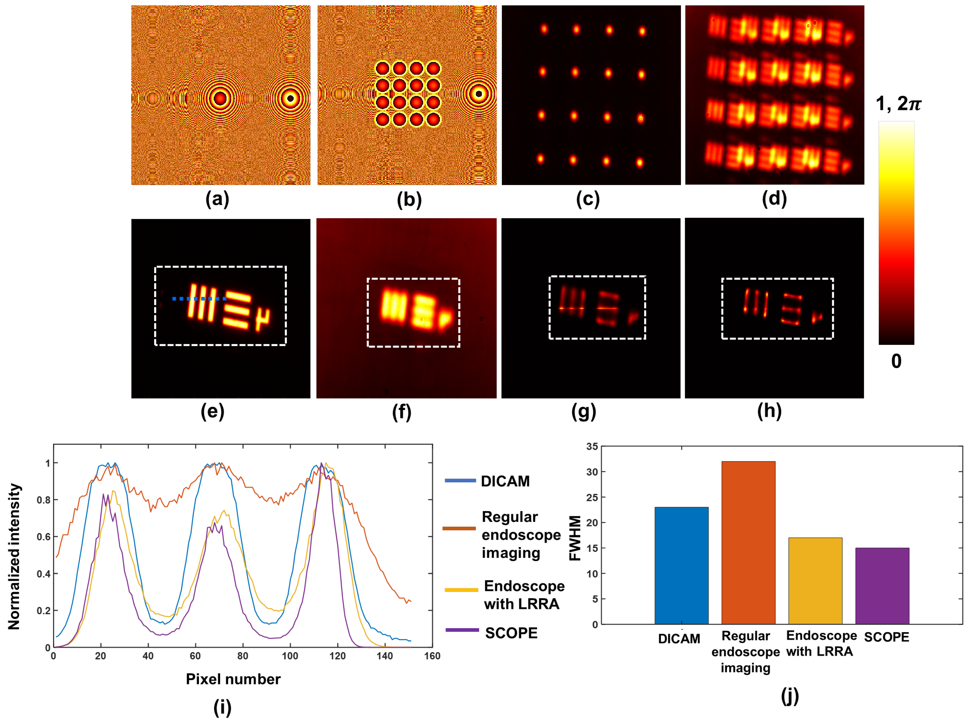

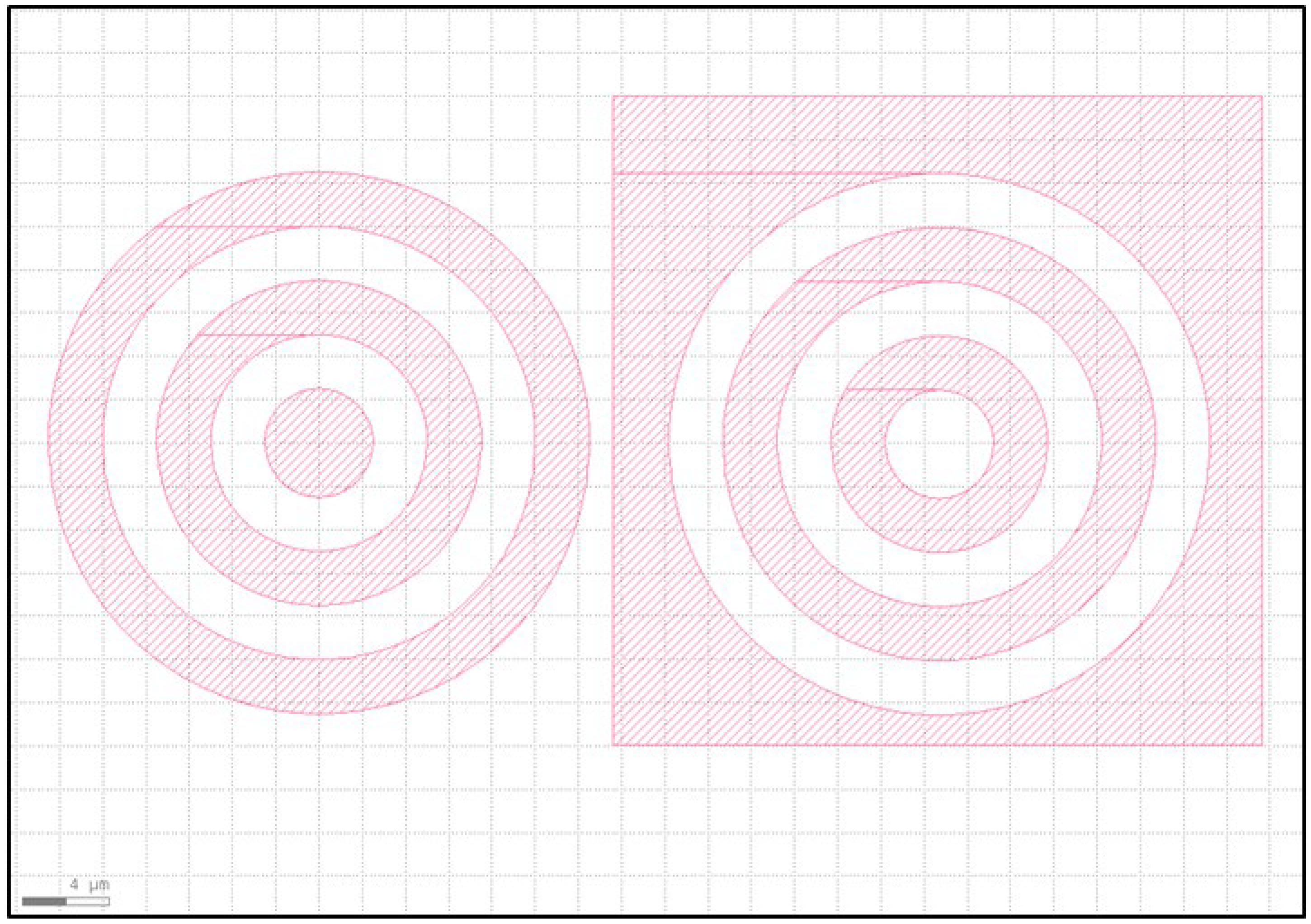

Disclaimer/Publisher’s Note: The statements, opinions and data contained in all publications are solely those of the individual author(s) and contributor(s) and not of MDPI and/or the editor(s). MDPI and/or the editor(s) disclaim responsibility for any injury to people or property resulting from any ideas, methods, instructions or products referred to in the content. |
© 2025 by the authors. Licensee MDPI, Basel, Switzerland. This article is an open access article distributed under the terms and conditions of the Creative Commons Attribution (CC BY) license (https://creativecommons.org/licenses/by/4.0/).