1. Introduction
Since the inception of deep-space missions, advancements in telecommunication technologies have played a pivotal role in enabling communication within an environment fundamentally different from conventional terrestrial networks. The primary challenges stem from the vast distances involved—rendering even the speed of light a limiting factor—and the inherently intermittent nature of connections due to orbital dynamics. Given the mission-specific characteristics of deep-space operations, Layer 2 (L2) customization was often sufficient to support communication over point-to-point links.
However, as communication requirements evolved to include multiple nodes, three main categories of solutions emerged. Some approaches modified existing protocols to better accommodate the conditions of space links [
1]; others enhanced protocol stack capabilities by introducing proxies [
2]; while still others developed application-layer solutions that implemented store-and-forward behavior [
3]. A common limitation across all these approaches is their lack of interoperability and their typically short mission lifespan, resulting in a fragmented ecosystem of protocols that are often agency- or even device-specific [
4,
5].
To prevent a future characterized by isolated and non-interoperable space networks, it became evident that the space communications community required a standardized, common solution for interplanetary networking [
6,
7].
The first attempt to define an architecture for the future space network was made in RFC4838 [
8], which introduced the concept of delay-tolerant networking (DTN), a network paradigm designed to face the challenges posed by harsh environments and conditions such as high delays and disruptions, also defining the features that a network should implement in order to counteract them. This came with the conclusion that, at the time, the traditional Internet Protocol (IP) suite did not have the capabilities to fit in this context. Consequently, the Bundle Protocol (BP) was designed, and two standardized versions have been implemented (so far): Bundle Protocol version 6 (BPv6) [
9] and the more recent Bundle Protocol version 7 (BPv7) [
10], offering a solution based on a store-and-forward mechanism that fundamentally works at application layer (L7) as an overlay of the underlying networks and directly below the applications. The main limit of this solution, which is also one of the motivations of this research, is that it requires source, destiny, and intermediate nodes with intermittent links to implement the BP, creating a network not interoperable with existing Internet nodes.
This limited interoperability with the terrestrial Internet, in the context of scientific agencies and strictly planned space missions, was reasonable and did not represent a crucial issue. However, in the era of the New Space Paradigm, with numerous private companies now conducting space missions and new sectors other than the scientific one launching their space programs, the lack of interoperability becomes a tangible problem. It is not hard to imagine that in the foreseeable future a user might want, for example, to use their smartphone to exchange emails between the Moon and Mars. This would require the packet to travel across many different nodes, some of which are non-DTN- and some others of which are necessarily DTN-enabled. To achieve this, an IP-compliant solution that enables packets to traverse the network regardless of the nature of the nodes is essential.
Thankfully, years of innovation and development of the IP, and in particular the introduction of Internet Protocol version 6 (IPv6), allow us to perform a re-evaluation of its possible application in deep space [
11]. Recent work in this field defends that a fully IP architecture is capable of providing interplanetary connectivity [
12], without the needed rework of existing infrastructure that BP requires. Some research work has already been carried out in this sense, and a notable example of this is the paper “Adding Support for Delay Tolerance to IPv6 Networks” [
13], where the authors managed to replicate DTN functionalities in the IP by developing a new hop-by-hop extension header. The main drawbacks of the design were the reduced scope and resilience of the solution and that it did not account for the fact that, as a general practice, many nodes discard packets containing the hop-by-hop option header [
14] to mitigate potential efficiency and security concerns.
Given the recognized success of the BP in DTN, and the peculiar position of IPv6 as the predominant networking protocol in existing networks, the aim of this article is to compare the functionalities of BPv7 and IPv6, investigating the possibility of replicating the main features of the first directly in the second. Then, we propose a new architecture for an IP-compliant DTN-capable node. Such a device would open the possibility of building an IP network that can operate over DTN environments. This node would provide DTN features while interoperating with existing IP networks, providing a solution also applicable to challenged terrestrial networks, like intermittently connected wireless sensor networks and Internet of Things (IoT) mobile ad hoc networks.
The remainder of this paper is organized as follows.
Section 2 analyzes the initial differences and similarities between BPv7 and IPv6, identifying the absence of functionalities that will then be addressed in
Section 3 with the description of the architecture.
Section 4 details the implementation process, including the modifications and enhancements needed to integrate the missing functionalities. Finally,
Section 5 summarizes the findings, discusses their implications, and outlines potential future work.
2. Comparative Study of BPv7 and IPv6 Functionalities
As described in
Section 1, we adopt BPv7 as a reference, as it represents the latest and most advanced iteration of the BP. Subsequently, we compare it to IPv6, focusing on their respective functionalities.
Both IPv6 and BPv7 are message-oriented protocols whose data unit structures are designed with modularity, facilitating extensibility through their respective extension mechanisms. In IPv6, the fundamental data unit is the packet, which can be augmented with extension headers to support additional functionalities such as fragmentation, routing, or hop-by-hop options. Similarly, BPv7 employs bundles as its primary data unit, which can be extended with Extension Blocks to incorporate various optional features. This common approach underlines the similarity between the two protocols and is a valuable resource to take into consideration for future extensions, or the porting to IPv6 of already existing BPv7 optional features such as Bundle Protocol Security (BPSec) [
15]. While both BPv7 and IPv6 share a modular structure and design in their use of Extension Blocks and extension headers, respectively, their approaches diverge significantly in other areas. For example, BPv7 employs schedule-aware routing and has optional status reporting, which are crucial tools for disrupted networks. In contrast, IPv6 relies on well-established routing protocols like Open Shortest Path First (OSPF) and Border Gateway Protocol (BGP), which are unfit for challenged networks. DTN-compliant algorithms such as Contact Graph Routing (CGR) [
16] would need to be implemented for IPv6 networks. Fragmentation handling also differs: IPv6 uses the Fragment Header, whereas BPv7 employs a custom fragmentation mechanism. Furthermore, BPv7 replaces the traditional hop limit of IPv6 with a lifetime expiration system for bundles, which is better suited for cases where messages may spend large periods in node storage awaiting a forwarding opportunity. Key features such as status report and store-and-forward mechanisms, native in BPv7, are entirely absent in IPv6. In general, the comparison highlights that while BPv7 and IPv6 share some design patterns, for the latter to operate in a DTN scenario the lack of a store-and-forward mechanism and a signaling mechanism must be addressed. The next subsections detail the related challenges in data and control planes.
2.1. Data Plane
Compared to the BP, IPv6 lacks a fundamental component: a way to manage packets in a store-and-forward manner. The need for a store-and-forward mechanism comes from the fact that, in DTNs, an end-to-end uninterrupted path may never be possible to achieve. The intermittent nature of the links, due to the changing network topology, the long propagation delays, and the high error rates of the links, make end-to-end connectivity quite challenging. Therefore, if a non-DTN node receives a packet, but the link on which it should be forwarded is down, this packet will normally be dropped by the stack. If an upper layer provides retransmissions, then this would trigger a full retransmission after a certain time, which will have a similarly low chance of reaching its destination. To address this problem, the idea is to equip intermediate nodes with storing capabilities to be used to store the packet and wait for the link to the next hop to become available. A mechanism for hop-by-hop reliability was included in BPv6 as the so-called “custody mechanism”; this implemented additional signaling between BP nodes that transferred custody of a bundle along the path. In BPv7, it was deemed as a non-core functionality and was removed in favor of end-to-end retransmission by the application, enabled by new status reporting added to BPv7. This provided a more flexible and less strict solution, while the stack now relied on the Licklider Transmission Protocol [
17], a widely used lower layer for the BP to provide hop-by-hop reliability. The IP suite is not equipped with such mechanisms, so an analogue solution must be designed.
In some implementations focused on point-to-point links, for example in European Space Agency (ESA) and National Aeronautics and Space Administration (NASA) missions, the store-and-forward mechanism is usually located at the data-link layer (L2) of the protocol stack [
18], as it can be implemented simply by defining policies on the interfaces and buffering the data there. However, the main drawback of this solution is that routing, performed at the network layer (L3), is computed at packet arrival and applied immediately. This means that a packet stored at an interface (L2) awaiting forwarding is forever bound to the decision taken at reception, even if alternative paths to the destination become available in the meantime. In the worst-case scenario, this may lead to data loss if the expected contact does not happen due to anomalies. For this reason, implementing the storage function at L3 directly inside IPv6 would provide a much greater degree of control and enable reactive routing, achieving efficient network usage.
2.2. Control Plane
All the mechanisms implemented to provide a DTN service need to be properly managed and coordinated, with the optional status report mechanism being a prime example of BPv7 control plane signaling. This mechanism helps the sending application to monitor and manage its bundles within a challenged network by establishing feedback loops that enable reliability and control. Similarly, IPv6 makes use of Internet Control Message Protocol v6 (ICMPv6) to report errors in the network but also as a signaling mechanism used by some IP suite protocols. Some functionalities of transport layer (L4) protocols, such as Path Maximum Transmission Unit Discovery, rely on ICMPv6 as transport. This suggests that a mechanism similar to BPv7 status report may be implemented while maintaining an IP-compliant structure.
We propose to replicate the status report mechanism into IPv6, as it is essential to establish a specifically tailored signaling system. This signaling must coexist with the standard control traffic used to manage any IPv6 network, all while remaining IP-compliant. The most straightforward and natural approach to achieve this is to leverage ICMPv6. By defining custom ICMPv6 messages, we can adapt them to serve our purpose. Typically, the IP relies on transport protocols like the Transmission Control Protocol (TCP), Stream Control Transmission Protocol (SCTP), or the increasingly popular Quick User Datagram Protocol Internet Connections (QUIC) [
19] (also in the context of DTN) to ensure reliability. In accordance with this approach, the objective of our mechanism is solely to signal the status of packet transmission, not to handle retransmission itself, and delegate this last task to the chosen L4 protocol.
Custom ICMPv6 messages can be defined by utilizing the unused type codes. It is important to note that a normal network node receiving such a message will not recognize it and will likely drop it. However, this is not expected to pose a problem, as DTN signaling is designed to be exchanged exclusively between DTN nodes. Intermediate network nodes are assumed to forward these messages as standard packets without interpretation, following the standard behavior of IPv6, which treats ICMPv6 messages like any other payload unless the node itself is the intended destination. Details regarding unused type codes and the forwarding of ICMPv6 packets are available in RFC4443 [
20].
It is worth considering that some intermediate nodes, particularly those with strict security policies or advanced firewall configurations, might inspect the payload of ICMPv6 packets and filter unknown type codes. While this should not affect typical IPv6 routing, it may require careful network configuration in tightly controlled environments to ensure that the custom messages are not blocked. Additionally, if a non-DTN node inadvertently receives a custom ICMPv6 message as the destination, it could generate diagnostic noise by logging or reporting the unrecognized type code.
In the long term, to ensure wider adoption and alignment with standardization initiatives, it would be ideal to collaborate with the Internet Assigned Numbers Authority (IANA) to reserve a specific range of type codes for DTN signaling. Such standardization would improve interoperability and minimize potential ambiguities in the deployment of DTN features.
2.3. Feature Analysis
This section provides a detailed row-by-row analysis of the comparison outlined in
Table 1 of the two standards, highlighting key features such as addressing, reliability support, routing, and fragmentation handling.
2.3.1. Data Unit
IPv6 uses packets as its fundamental data unit, augmented by extension headers that add functionalities such as fragmentation or routing, while BPv7 employs bundles extended via Extension Blocks. Both designs embrace modularity, although BPv7’s bundles are optimized for DTN environments. Given this similarity, IPv6’s modular approach could be adapted by defining new extension headers that replicate BPv7’s DTN-specific features.
2.3.2. Addressing
IPv6 employs 128-bit addresses that serve as both identifiers and locators, a dual role that can be problematic in highly mobile environments where a node’s IP address might change. In contrast, BPv7 uses Endpoint Identifiers (EIDs) to decouple the identity of a node from its location, ensuring a persistent identifier even when network addresses vary. Another key feature of BPv7 addressing is late binding, which allows the resolution of an endpoint identifier to a specific next-hop address only when forwarding is required, a mechanism particularly useful in networks with intermittent connectivity or dynamic topology changes.
However, in our research context where spacecraft operate within a single defined network and do not switch between different domains, their IP addresses remain static. Consequently, the primary advantages of EIDs and late binding are less pronounced here, making IPv6 addresses a sufficient choice. This vision is shared by researchers involved in the activities of the Internet Engineering Task Force (IETF) “tiptop” working group, which is drafting a request for reserved IPv6 address spaces for out-of-Earth nodes [
21].
2.3.3. Support for Reliability
As explained before, IPv6 lacks reliability at the network layer and typically delegates the task to transport-layer protocols. Unlike its predecessor BPv6, which supported retransmissions via custody transfer, BPv7 does not perform retransmission itself. Instead, it provides optional status reporting to the application layer, leaving it to the application to decide whether to retransmit lost data. Reliability at the link layer is handled separately using the Licklider Transmission Protocol (LTP).
While IPv6 does not inherently support these characteristics, it could be extended with a custom signaling mechanism, potentially using ICMPv6, to emulate BPv7’s status report mechanism without compromising IP compliance. This approach would establish a parallelism between the BPv7 model, where the protocol reports status and the application manages retransmission, and an IPv6-based solution, where ICMPv6 reports status while a transport layer protocol handles retransmissions.
2.3.4. Routing
Routing in IPv6 and BPv7 networks reflects their fundamentally different design goals. IPv6 relies on dynamic routing protocols such as OSPF and BGP, which assume continuous connectivity and low latency between nodes. These protocols compute routes based on the network topology discovered in real time, enabling efficient and reliable packet forwarding in traditional Internet environments. In contrast, BPv7 is designed for Delay-Tolerant Networks (DTNs) and employs a schedule-aware or time-variant routing approach tailored to intermittent connectivity. Algorithms like CGR are used to determine optimal forwarding paths based on predicted contact opportunities, addressing disruptions and high latencies. While IPv6 usually forwards packets based on pre-computed routing tables, BPv7 commonly performs per-packet routing decisions to take into account the network congestion forecast, with the option to recompute the forwarding decision if changes occur while in storage. BPv7 implementations already present the flexibility needed to handle this type of routing, while the IPv6 suite does not currently contemplate such schedule-based or reactive routing. Therefore, adaptations of the stack and the implementation of routing protocols like CGR are necessary for IPv6 to operate in DTN.
2.3.5. Fragmentation
Fragmentation in IPv6 is managed by a dedicated Fragment Header that efficiently segments and reassembles packets, whereas BPv7 uses a custom fragmentation mechanism designed for the challenges of DTNs. IPv6’s approach could potentially be enhanced for DTN use by refining fragmentation policies or extending the Fragment Header to account for longer delays and reordering issues typical in disrupted networks.
2.3.6. Time to Live
IPv6 uses a hop limit field to prevent indefinite packet circulation, decrementing the value at each hop. BPv7 instead implements a lifetime expiration mechanism or Time-To-Leave (TTL) for bundles, which is more suited to the long delays in DTN environments. Adapting IPv6 for DTNs might involve modifying the interpretation of the hop limit, extending IPv6 with a TTL feature, or relying on other mechanisms to remove no longer useful packets from the network.
2.3.7. Store and Forward
IPv6 lacks an inherent store-and-forward capability at the network layer, limiting its performance in scenarios with intermittent connectivity. In contrast, BPv7 integrates store and forward as a core feature, enabling nodes to store data until transmission is feasible. To adapt IPv6 for DTN scenarios, developers must consider embedding store-and-forward functions directly at the network layer, allowing dynamic re-routing and queuing similar to BPv7’s approach. This, in turn, requires the addition of storage capacity as another resource to manage in store-and-forward nodes. Still, long-term storage space is not a new issue, as current intermittently connected wireless sensor and LEO networks already deal with it in vendor-proprietary and mission-specific ways. Moreover, a storage management strategy must be designed based on factors such as data priority, expiration time, etc. This will improve the utilization rate of storage resources.
2.3.8. Compatibility
IPv6 is fully compatible with the existing Internet infrastructure, allowing seamless interoperation between a wide range of standard nodes. In contrast, BPv7 is specifically designed for delay-tolerant networking, and disruption management requires that every node involved in an intermittent link in the communication path implement its DTN-specific functionalities for the protocol to work.
Another beneficial aspect of using the IP stack is the existence of network management protocols that, with proper profiling, can work for DTN and non-DTN nodes [
22,
23]. Such a solution for the BP is still in development and will require a separate management process from the rest of the existing internet nodes.
3. Architecture Proposal
An architecture has been designed to implement a DTN node capable of handling both DTN and non-DTN traffic while maintaining IPv6 compliance. This approach circumvents the limitations of previous solutions (e.g., the Bundle Protocol), which required existing nodes, some not directly affected by disruptions, to modify their protocol stacks.
To avoid the challenges of modifying the Linux kernel, the solution can be implemented with LightWeight IP (LwIP) [
24], which also allows better control of the stack. LwIP is an open-source, lightweight implementation of the Linux networking stack, optimized for constrained devices, an advantage particularly relevant for DTNs. In addition to the protocol stack, LwIP provides a library of APIs that developers can use to integrate and interact with the functionalities of the stack.
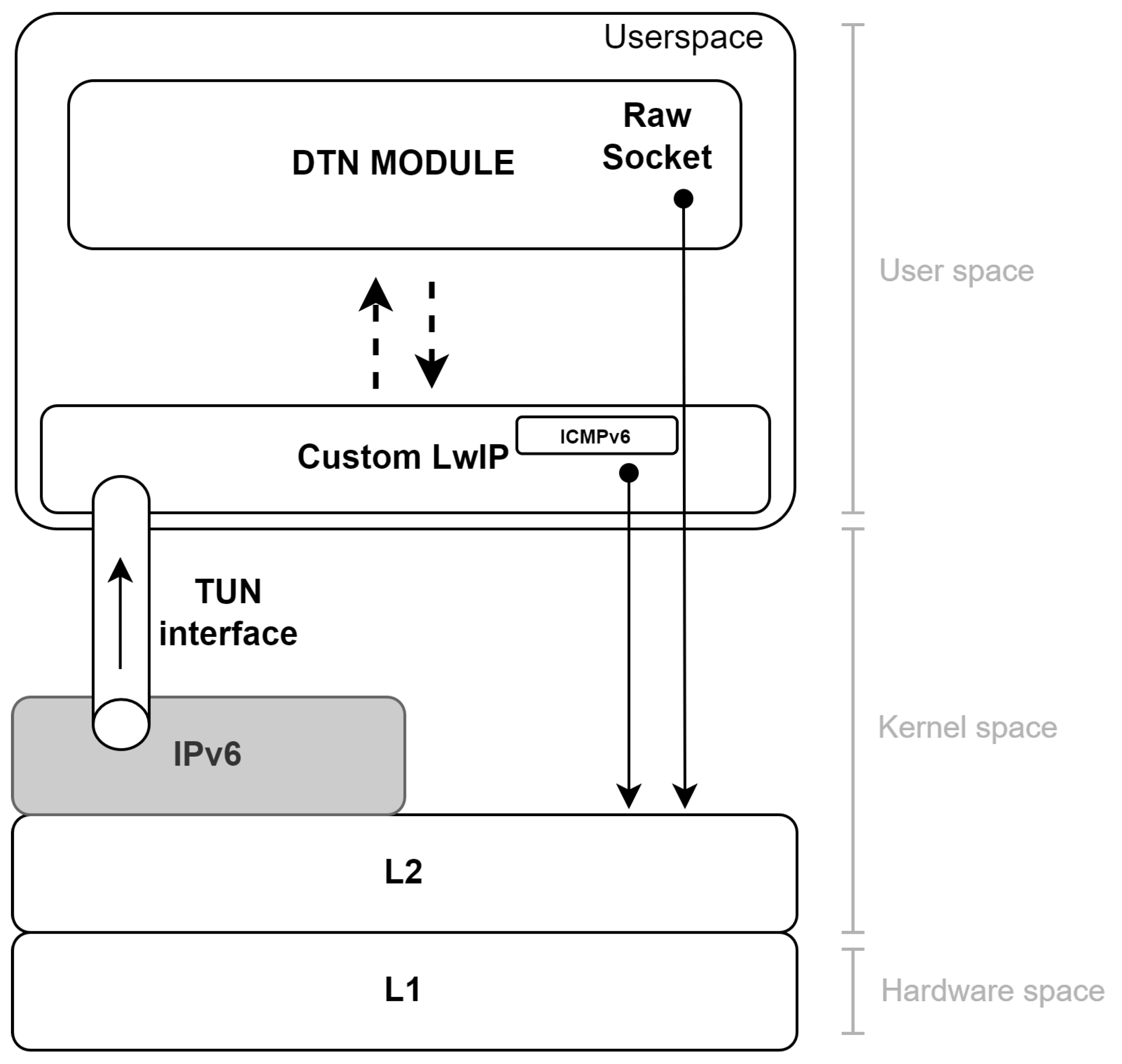
Figure 1 provides a schematic representation of the design of a node.
To implement the proposed design, a network TUNnel (TUN) interface is established between the kernel and the userspace, instructing the kernel to forward all inbound IP packets to this interface without further processing of the headers. Once in the userspace, the IP packets are processed by an LwIP instance enhanced with an additional DTN Module. This implements the DTN functionalities needed in a modular way through custom and specialized functions. DTN packet forwarding completely bypasses the IP stack implemented in the operating system kernel, using raw sockets to deliver the IP packets directly to the correct L2 interface. This is necessary because, otherwise, once the packet is handed back to LwIP, the routing decisions made by the DTN Module would be disregarded, and the packet would not be forwarded in a DTN-aware manner. This approach ensures fine-grained control over DTN traffic flow.
The modular design and placement of the proposed solution in the userspace presents significant advantages, particularly in terms of testing and maintenance. For example, it allows for straightforward substitution of the routing algorithm or the definition of new signaling messages without requiring extensive modifications. However, to support the continued development and widespread adoption of the architecture, a native implementation within the operating system kernel should be considered. Such integration has the potential to enhance performance, simplify operation, and increase the robustness and efficiency of the solution in production environments.
3.1. DTN Module
The DTN Module is a userspace-executed logical entity that encapsulates all the essential components required to augment IPv6 with the capabilities necessary to support DTN communications. Although its internal implementation may vary depending on specific use cases or environments, its functionality can be abstracted at a macro level. The module must implement all the features necessary for storing packets, thereby enabling the store-and-forward functionality essential for DTN. In addition, it must incorporate the logic required to process incoming signaling traffic related to DTN operations and, when necessary, generate new signaling messages. This combination of packet storage and signaling processing ensures that the node can effectively participate in DTN communications while maintaining compatibility with existing IPv6 infrastructures.
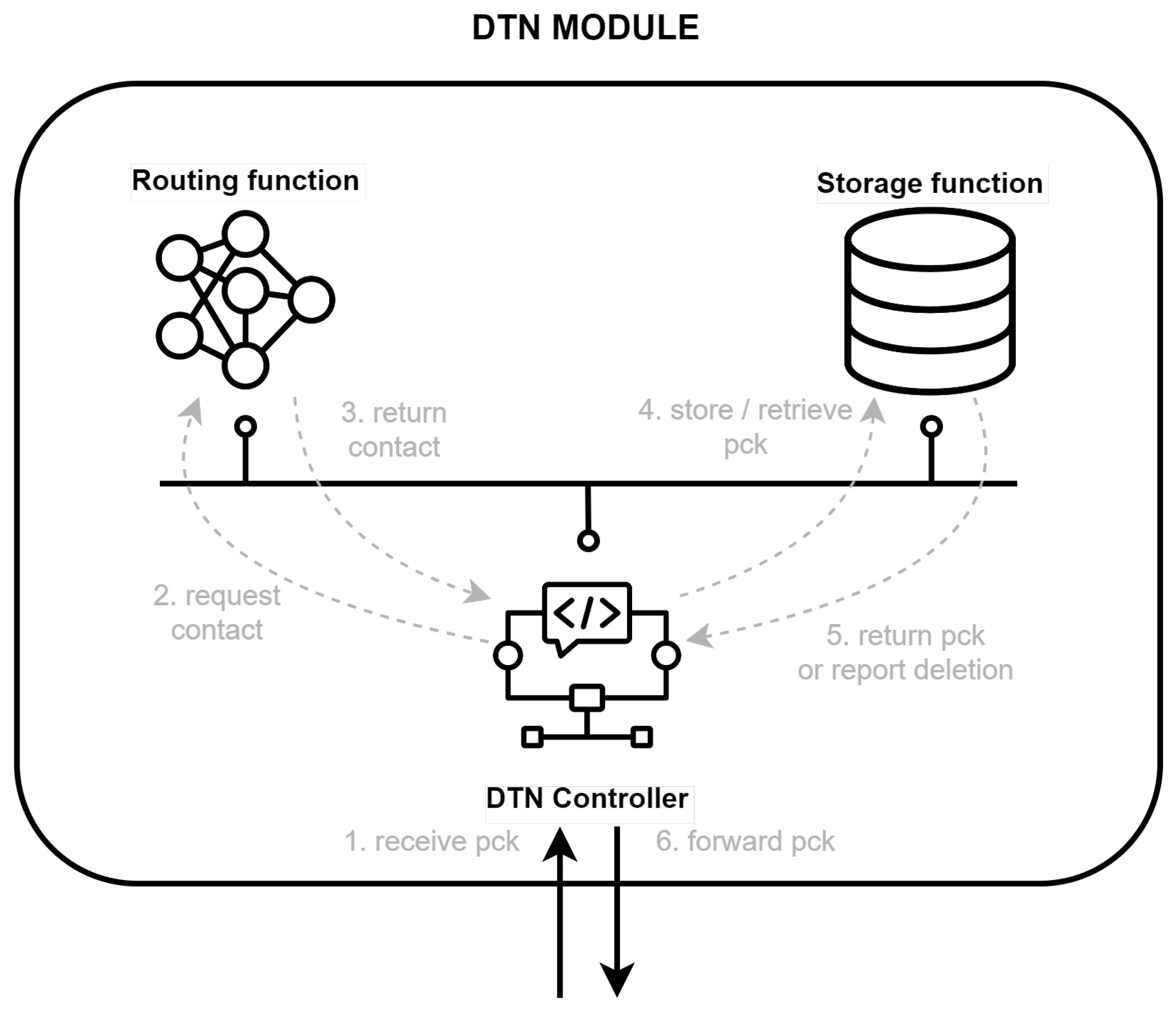
Figure 2 shows the elements of the DTN Module and a non-exhaustive example of the most fundamental interactions between them.
For the internal implementation of these functions, it is suggested to follow a Network Function Virtualization [
25,
26] approach, and to implement them as independent and heavily specialized entities. Based on this methodology, three primary candidates have been identified to fulfill the key functionalities of the module: the DTN Controller, responsible for overseeing and coordinating DTN operations; the Routing Function, which manages dynamic routing decisions to support intermittent and delay-prone links; and the Storage Function, which provides the necessary buffering capabilities to support the store-and-forward paradigm.
Figure 2 shows the interactions between the DTN Controller and the rest of the architecture elements and functions.
3.1.1. DTN Controller
As shown in
Figure 1, the DTN Controller serves as the central processing entity for all incoming or outgoing DTN packets, and is therefore responsible for all interactions between the DTN Module and the custom LwIP. Upon receiving a packet (message 1. receive pck), the DTN Controller analyzes its nature and determines the appropriate handling procedure. If the packet is to be forwarded, it interrogates the Routing Function for a contact (message 2. request contact), which evaluates and reports whether the packet should be stored or forwarded based on the current network conditions and routing logic (message 3. return contact). At the same time, if the packet is identified as signaling traffic, it is also processed directly by the DTN Controller. Depending on the content of the signaling message, a variety of actions may be triggered, ranging from updating routing information to generating new signaling messages or interacting with other functions. This ability to differentiate and appropriately manage user plane and signaling packets ensures the efficient operation of the DTN Module and the overall DTN communication system.
3.1.2. Routing Function
The primary goal of the Routing Function is to provide forwarding (or storage) decisions when requested by the DTN Controller, abstracting the routing algorithm specifics from it. It should implement algorithms specifically designed for routing in DTN networks. Among these, the most promising candidate is the CGR algorithm [
27], which has been extensively studied and is available in multiple implementations. The Routing Function must interface seamlessly with the DTN Controller by receiving route requests and responding with the computed forwarding decision and the timing of the next available contact. This functionality is critical for ensuring efficient store-and-forward operations in DTN environments, as it allows the node to make informed decisions about whether to store a packet temporarily or forward it immediately. By leveraging advanced routing strategies, such as congestion-aware routing, this function plays a key role in optimizing network performance in DTN scenarios.
3.1.3. Storage Function
The Storage Function constitutes the core element of the store-and-forward paradigm, an essential part of the DTN architecture. Its principal function is to remember DTN packets when immediate transmission is not feasible due to contact unavailability.
This function must be capable of efficiently managing data storage and retrieval to support interactions with other components, particularly the DTN Controller. When a packet is received and the next contact is unavailable, the Storage Function keeps the packet until it can be forwarded. In
Figure 2, upon receiving a request from the DTN Controller (message 4. retrieve pck), the Storage Function retrieves the stored packet and makes it available for transmission.
In addition to basic storage functionality, the function must incorporate advanced features to ensure smooth operation in a DTN environment. For instance, it must manage packet queuing and prioritize packets based on urgency, taking into account factors such as expiration times or quality of service (QoS) requirements. The management of storage resources is an issue not bound to a single protocol or solution. Active Queue Management (AQM) will surely be required, as it is in any node that implements buffers (or long-term storage, as in our case). A deeper analysis is left for future use case study, since different algorithms can impact the final performance. Given the often constrained resources of DTN nodes, the function must also optimize storage utilization by employing memory-efficient data structures and algorithms. Ensuring the integrity and reliability of stored data is critical, and the function should implement mechanisms to verify data integrity and prevent data loss caused by storage failures or power failures. For this reason, it is also crucial that these functionalities are implemented with persistent memory.
Furthermore, the Storage Function must include capabilities for removing expired or redundant packets to free up space for new packets. Upon packet deletion, the DTN Controller must be notified, as illustrated in
Figure 2 (message 5: report deletion). This triggers signaling messages, such as DTN-PCK-DELETED, which inform other DTN nodes of the deletion event and its causes. Detailed explanations of these and other signaling messages are provided later in this document.
One of the key challenges in implementing the Storage Function is balancing limited storage resources with the potentially high volume of delayed traffic. The implementation must incorporate timers to manage the lifecycle of stored packets. Timers must be used to periodically ask the DTN Controller if there is a new opportunity to forward the stored packets, and to ensure that stored packets are retained only for their valid duration, aligning with quality of service (QoS) requirements and preventing the storage system from being overwhelmed by outdated or irrelevant traffic. By discarding packets after their expiration, the system can free up storage space for new incoming traffic and maintain overall efficiency.
3.2. Custom ICMPv6 Messages
As previously identified, the status report messages defined in RFC9171 [
10] for BPv7 lack an IP equivalent. Our proposal is to leverage the ICMPv6 functionalities outlined in RFC4443 [
20] to signal DTN-specific information using a mechanism similar to status report. This effectively allows the upper layer to implement retransmission-based end-to-end reliability using the reported information. Next, we present the type and codes of the proposed ICMPv6 messages; its payload; a routing, processing, and security concerns discussion; and a control flow example.
3.2.1. Type and Code Messages
To maintain a clear distinction between the standard signaling of ICMPv6 and DTN signaling, this work proposes the introduction of four new ICMPv6 message types:
DTN-PCK-RECEIVED: Indicates that a packet has been successfully received by a node. Sent in the reverse direction, from the receiving node back to the sender or an intermediate node.
DTN-PCK-FORWARDED: Confirms that a packet has been forwarded to the next node in the network. Sent by the forwarding node to the sender or an intermediate node as a status update.
DTN-PCK-DELIVERED: Signals that a packet has reached its final destination. Sent from the destination node to the original sender or an intermediate node as a delivery confirmation.
DTN-PCK-DELETED: Reports that a packet has been deleted due to specific conditions (e.g., lifetime expiration or storage constraints). Sent from the node deleting the packet to the designated reporting node.
These message types utilize the code field to convey detailed status information. Although a comprehensive list of codes cannot be finalized at this stage, the BPv7 codes defined in the IANA subregistry can be used as a reference. A standardized pairing conforming to the requirements of ICMPv6 should be investigated through implementation and testing. There exists a standardized process. First, it is necessary to present an IETF draft, and when approved and published as an RFC, the IANA will assign the requested ICMPv6 types/codes, and update the ICMPv6 registry with the new entry. The impact on real-world environment is low since in any case, specific protocols must be deployed for DTN. The advantage is the complete compatibility with IP nodes.
Table 2 list the BPv7 status report Reason Codes and
Table 3 the custom ICMPv6 types and codes.
3.2.2. Payload
Building upon the BPv7 status reports’ defined structure, the payload of these ICMPv6 messages can include further details. Relevant information could encompass the creation timestamp of the reported packet, fragmentation-related data such as the fragment offset and payload length, and details about applicable security measures or other metadata. While the source IP address of the reported DTN packet could theoretically be included, this information is redundant since it is already represented as the destination address of the ICMPv6 packet. Further refinements to the payload structure will depend on practical implementation and testing experiences, given that even BPv7 does not provide definitive guidance in some areas.
3.2.3. Routing and Processing
The proposed approach follows the BPv7 model as its primary solution. In this model, the destination IP address of the ICMPv6 message is set to the address reported as the sender in the packet, so that status reports are sent back to the original transmitter. This enables the sender or higher-layer protocols to assess the delivery status and decide if retransmission is required.
3.2.4. Custody Transfer
In more complex or highly partitioned networks, the assumption that the status report can always reach the original sender may not always hold. To address the extreme cases when the sender is no longer reachable, thereby completely disrupting communication reliability, an alternative mechanism could be implemented by adding a “custodian” IP address within the transmitted data packet itself. This can be achieved using the IPv6 hop-by-hop options header, which is specifically designed to carry optional information that may be examined and processed by every node along the delivery path of a packet [
28]. Historically, the use of the hop-by-hop options header was considered infeasible, as RFC2460 [
14] required all intermediate nodes to process the header. Packets were often dropped when intermediate nodes encountered unrecognized options, significantly reducing reliability. Recent updates in RFC8200 [
28], RFC9288 [
29], and RFC9673 [
30] revise this behavior by specifying that not recognizing the content of the options header is not a sufficient condition for dropping the associated packet. Instead, nodes are instructed to forward packets while ignoring unknown options.
Leveraging this updated behavior, the hop-by-hop options header could store the IP address of the last traversed DTN node, considered the custodian of the packet since it keeps a copy of the packet. Intermediate DTN nodes would be responsible for overwriting this field to keep it updated as they accept custody for the packet. By utilizing this mechanism, the updated “last traversed DTN node” address could be used as the destination for the custom ICMPv6 packet, thereby hinting at a BPv6-like custody transfer mechanism where the last forwarder becomes the custodian and reporting target. To support this custody transfer mechanism, the logic of the DTN Module should also be extended in order to retain a copy of the forwarded packet until a new node accepts custody.
Note that this mechanism would partially break the best-effort nature of the IP, as it would add to L3 responsibilities related to retransmission and reliability, which normally belong to upper-layer protocols. For this reason, this solution must be considered only for extreme cases where end-to-end reliability through status reporting has been statistically deemed as unfeasible.
3.2.5. Security Concerns
While the proposed architecture enables comprehensive monitoring and control, it also raises potential security concerns. IPsec is the native security mechanism in IPv6 networks. One of its operation modes is the “Transport Mode”, which enables the encryption and integrity protections of the IPv6 payload without involving the IPv6 header. When applied to our design, the usage of IPsec treats the ICMPv6 header and payload as the payload of the IPv6 packet, which means our design can benefit from both authentication and integrity protection. When it comes to the proposed custody transfer mechanism, since the custodian information is carried as part of an extension header, IPsec does not protect it. This leaves it vulnerable to attacks, specifically to tampering by intermediate nodes. There is no easy solution, as modification of the hop-by-hop header by the intermediate DTN nodes is an integral part of the custody transfer mechanism. These required modifications prevent the application of integrity protection to the headers, and the encryption of IPv6 headers is not possible in a non-private network.
3.2.6. Flow Example
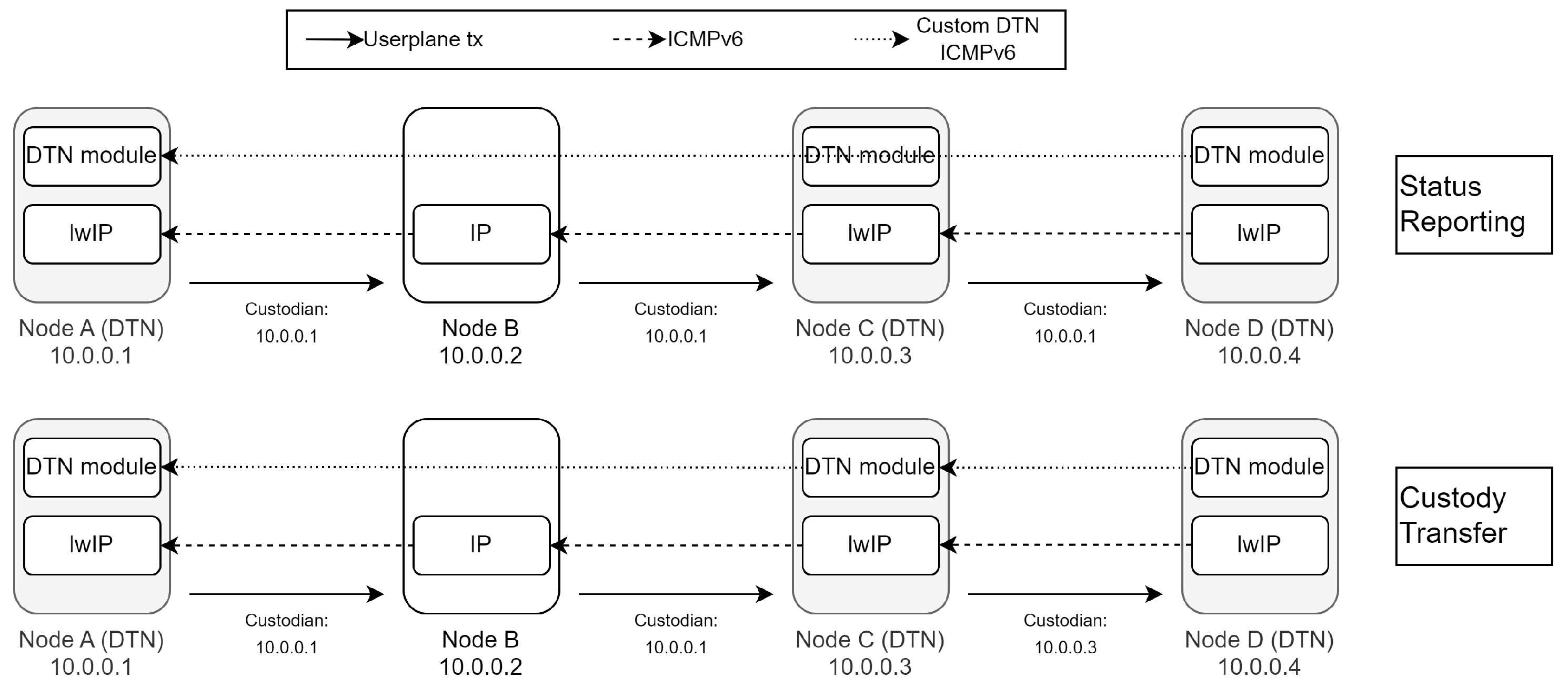
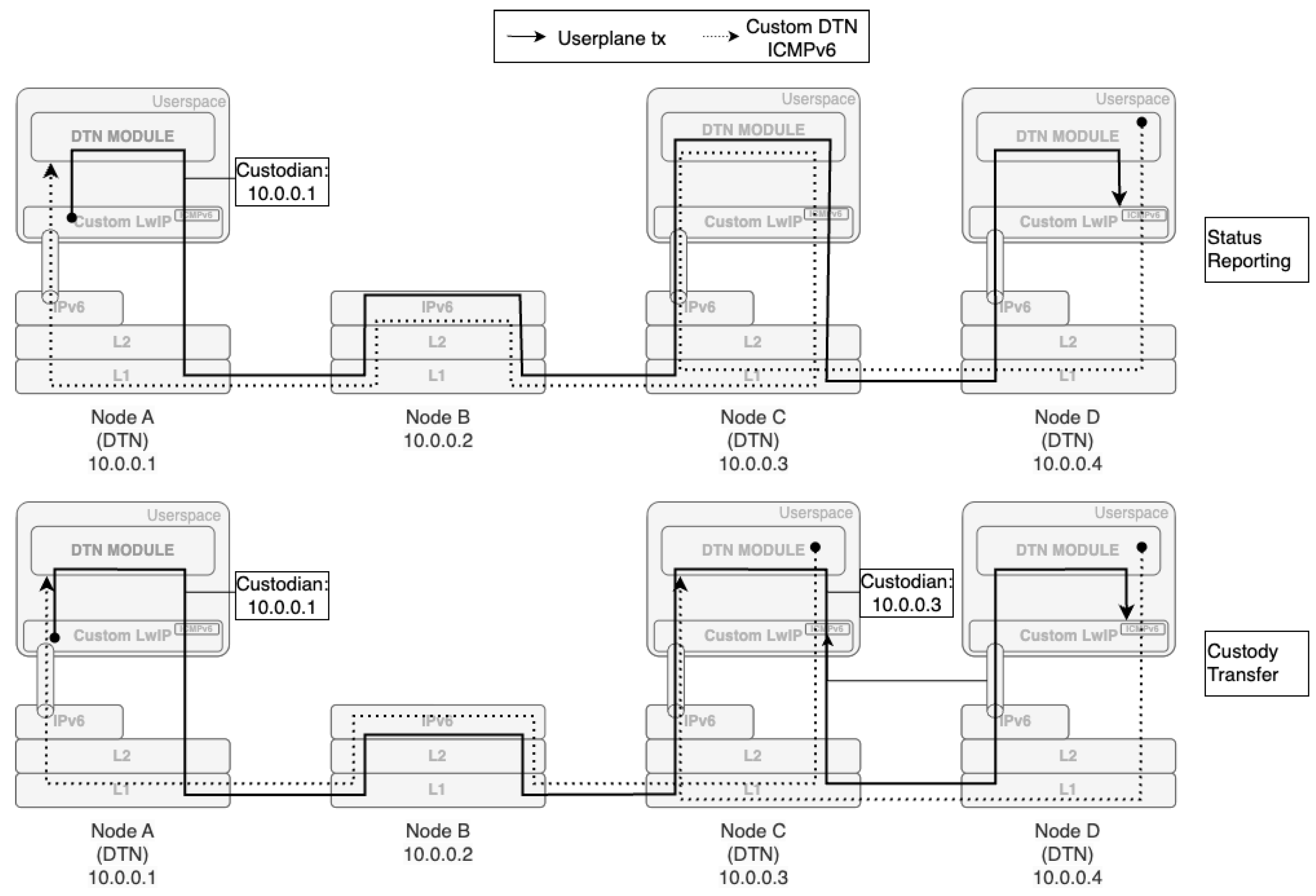
Figure 3 and
Figure 4 illustrate the modified control flow for the two proposed approaches. In this example, user plane transmission happens between DTN Node A and DTN Node D, with the packet being routed through an intermediate node that operates as a standard, unmodified IP node (Node B). If using custody transfer, before forwarding the packet, Node A writes its own address into the hop-by-hop option header. As discussed, this ensures that the packet contains a custodian address that can later be used for custody transfer purposes. The intermediate IP node (Node B), which does not recognize the custom hop-by-hop option header, simply forwards the packet to the next hop (Node C) without processing or modifying it. Node C, being equipped with DTN capabilities, recognizes the hop-by-hop option header of the inbound packet and, if the network is operating with custody transfer, reports custody acceptance to the previous custodian, stores a copy of the packet, replaces the custodian address with its own, and forwards the packet to the next hop (Node D), when possible. Otherwise, if the network relies only on status reporting, the node will temporarily store the packet and forward it without modifying its header. Upon successful receipt of the user plane packet, Node D, as a DTN-capable node, generates a custom ICMPv6 message DTN-PCK-RECEIVED and sends it to the address of the packet sender. When comparing the two methods, the most immediate difference is that, in the custody transfer case, a retransmission responsibility is assigned to the custodian node, and is iteratively moved closer to the destination as the transmission progresses. This feature is not present in the status reporting mode, as it breaks IP compliance by implementing retransmission functionalities at L3. As a result, when the nodes operate in status reporting mode, the communication follows a standard end-to-end flow, whereas in custody transfer mode, communication occurs on a “DTN_Hop-by-DTN_Hop” basis.
4. Implementation Strategy
This section outlines the practical steps for implementing the proposed architecture to integrate DTN features into IPv6. The implementation focuses on leveraging custom code run in the userspace, enhancing the LwIP stack, and building a modular DTN system with custom ICMPv6 signaling. The primary goals are to ensure modularity, interoperability with existing IPv6 systems, and efficient handling of intermittent connectivity. The following implementation is designed for Linux due to its robust support for virtual network interfaces.
4.1. TUN Interface Setup
A TUN interface is used to bypass the kernel’s L3 networking stack, redirecting IP packets to the userspace, where LwIP and the DTN Module process them. This approach enables customized processing and flexible handling of IP traffic, which is essential for implementing DTN-specific features. The interface is created using the ip tuntap utility, a Linux tool designed to facilitate communication between the kernel and userspace. For this implementation, the TUN interface, named dtn0, must be initialized in TUN mode, which is specifically designed for L3 packet handling. After its creation, the interface must be configured to ensure it operates correctly and directs all relevant traffic through the TUN path. Once initialized, an appropriate IP address must be assigned to the interface, and consequently it must be brought into an active state to allow communication. This ensures that the interface is fully integrated into the networking stack of the system. To achieve the desired behavior, it is necessary to configure the routing rules so that all traffic is forwarded to the TUN interface. By setting the TUN interface as the default route, all inbound traffic is redirected through it, ensuring proper packet interception and processing by LwIP and the DTN Module.
4.2. LwIP Setup and Userspace Execution
To set up LwIP for userspace operation, the stack must first be configured and compiled. Customization is performed by editing the configuration file, typically named LwIPopts.h, which defines parameters such as protocol support, buffer sizes, and threading models. For this implementation, LwIP is configured in a single-threaded, event-driven mode to simplify integration with the DTN Module. This configuration ensures support for IPv6, User Datagram Protocol (UDP), and other protocols relevant to DTN operations. Once configured, the stack is compiled into a userspace library using a suitable build system, such as make or cmake. Platform-specific adjustments, such as timing mechanisms and network interface integration, are applied during compilation to ensure compatibility with the target system. On Linux, the netif module is customized to interface with both the TUN device for input and raw sockets for output.
4.3. DTN Module Implementation
The DTN Module operates as an event-driven system that processes packets based on the state of the network and the requirements of the delay-tolerant protocol. Its implementation involves several components working in harmony to provide robust DTN functionalities. No strict guideline is available as of now for its implementation, but sticking to the structure outlined in the previous section, it is suggested to rely on already existing work and customize it for our needs. For instance, a wide variety of implementations of CGR are available, so an implementation from scratch of the Routing Function is not necessary. What is more relevant to discuss is its integration with LwIP. This is achieved through a custom hook mechanism tailored to intercept targeted traffic at essential points in the LwIP processing pipeline. The hook must be implemented within functions such as ip_input() or ip_forward() in the LwIP stack. These functions are responsible for processing inbound packets and forwarding packets not destined for the local node, respectively. The hook inspects each packet and determines whether it meets the criteria for DTN processing. Criteria may include checks on the destination IP address, protocol fields, or application-layer identifiers.
4.4. Hybrid Forwarding Mechanism
Forwarding in this system employs a hybrid approach that combines the reinjection of packets into LwIP together with the use of raw sockets, depending on the routing requirements determined by the DTN Module. This ensures that the system balances compatibility with standard networking behaviors and the flexibility required for delay-tolerant networking. Packets processed by the DTN Module are either returned to LwIP or forwarded directly via raw sockets. When reinjected into LwIP, the packet follows the normal forwarding pipeline, which includes default routing, ICMPv6 generation, and protocol-specific handling. This path is used for traffic that does not require specialized routing or modifications to its headers. For packets requiring custom routing decisions, raw sockets provide a direct forwarding path. The DTN Module must construct the necessary headers, sets the appropriate destination address, and specifies the outgoing network interface. The raw socket bypasses LwIP’s routing logic, ensuring that the packet adheres to the DTN Module’s routing decision. This approach is particularly advantageous for scenarios involving opportunistic forwarding, experimental protocols, or non-standard traffic. The choice between reinjection and raw socket forwarding is dynamically determined based on the packet’s routing requirements. This hybrid mechanism enables the system to handle both standard and DTN-specific traffic efficiently, ensuring seamless integration of advanced routing functionalities without compromising compatibility with the existing networking stack.
5. Conclusions
This work explores the integration of DTN functionalities into IPv6 using ICMPv6, proposing a novel approach to address the challenges of deep-space communications. By comparing BPv7 and IPv6, we identified critical gaps in IPv6, such as the lack of store-and-forward mechanisms and suitable signaling for disrupted environments. To bridge these gaps, we proposed a modular architecture leveraging the LwIP stack and custom ICMPv6 messages to enable DTN capabilities while maintaining IPv6 compliance. Our design enables the coexistence of DTN and non-DTN traffic, ensuring interoperability with existing terrestrial infrastructures and expanding the usability of DTN solutions to new applications, such as IoT devices in challenged environments. As highlighted in this paper, the impact of our solution is limited to the addition of an extension header, which according to published standards should not cause incompatibility with existing networks. Furthermore, the modular design facilitates future enhancements and allows for easier testing and deployment in constrained devices.
While this architecture demonstrates the potential for extending IPv6 to support DTN requirements, its implementation and validation in real-world scenarios will be critical for assessing its performance and scalability. Key areas for further research include addressing security concerns associated with ICMPv6-based signaling and exploring the implications of persistent storage on resource-constrained devices.
This work sets the foundation for a new generation of IP-compliant DTN solutions, bridging the gap between terrestrial and non-terrestrial networks and enabling seamless communication across diverse infrastructures. By leveraging the strengths of IPv6 and adapting it to meet the challenges of DTN environments, we pave the way for a more interoperable and flexible networking paradigm.


