Abstract
This paper starts with an overview of current methods of displaying 3D objects. Two different technologies are compared—a glasses-free 3D laptop that uses stereoscopy, and one that uses front projection on a silver impregnated fabric screen that diffracts light to achieve a holographic effect. The research question is defined—which one is suitable for use by specialists. A methodology for an experiment is designed. A scenario for finding the solution to the problem during the experiment is created. An experiment environment with different workstations for each technology has been set up. An additional reference workstation with a standard screen has been created. Three-dimensional CAD models from the field of mechanical engineering were chosen. Different categories of defects were introduced to make the models usable for the scenario—finding the defects in each of the different workstations. A survey for participant feedback, using several categories of questions, was created, improved, and used during the experiment. The experiment was completed, short discussions were held with each participant, and their feedback was analyzed. The categories of the participants were discussed. The results from the experiment were discussed and analyzed. Statistical analysis was performed on the survey results. The applicability of the experiment in other fields was discussed. Conclusions were made, and the comparative advantages and specifics of each technology were discussed based on the analysis results and the experience gained during the experiment.
1. Introduction
As visualization technologies advance, two new ways of displaying 3D objects have become available recently. One of them is the glasses-free stereoscopic display laptop, which uses cameras integrated in its front panel, right above its monitor. It uses the effect of stereoscopy to display 3D images by tracking the eyes, removing the need for using the special glasses that come with its all-in-one predecessors. This type of technology is currently seeing applications in education [1,2] and training [3]. Another is a holographic simulation that allows for the creation of holographic illusions by using front projection. The technology embeds thin silver threads in its display that reflect light at a high enough level to create bright 3D projections and holographic effects. The method is dependent on the light conditions, and in the perfect environment, the parts of the image that contain no objects are omitted and disappear for the viewers. This in turn creates the illusion that the objects actually exist in reality and are not part of a display. Microsoft HoloLens was considered for evaluation as a fourth workstation, as there are interesting applications for mixed reality and augmented reality that can be explored [4], but they necessitate their own dedicated research and experiments. Virtual reality was also considered, as there are great applications for the technology already, such as cultural tourism [5] and investigating mental stress [6], and in general, 3D technology has introduced various changes to our ways of viewing data [7]. Researchers are searching for ways to enhance visualization, and some have successfully integrated large displays in virtual reality environments to enhance user experience [8]. The effects of stereoscopic 3D displays on visual fatigue and operating performance have been researched [9]. Scientists have optimized the techniques to limit user fatigue when watching such displays by calculating the positions of the viewers’ eyes during movement, thus correcting the 3D projections [10]. Techniques for holographic 3D displays that do not use glasses, and their bottlenecks, have been discussed, and possible algorithmic solutions have been investigated [11]. Innovative holographic near-eye display systems have been created, and prototypes have been tested to expand the lightweight options that may become available for easier use of the technology [12]. The field of 3D visualization is advancing tremendously, and there is room to grow in the direction of physical representation of objects using shape displays [13]. There is a significant variety of technologies for volumetric visualization [14]. Researchers have experimented with visualization technologies for mechanical engineering. Some described their experience with using 3D virtual reality environments and mobile augmented reality applications for teaching mechanical engineering students [15]. Others presented similar mobile augmented reality applications for interacting with 3D objects in engineering education [16]. Details on near-eye display and tracking technologies and their application in visualizing 3D objects have been documented by others [17]. A low-cost prototype, called EducHolo, was developed by scientists [18]. It enables the visualization of holograms on tablets, which were used by students to visualize holograms of mechanical parts. Most of the technologies that can help mechanical engineers for the maintenance and repair of automobile and mechanical equipment are reviewed in detail elsewhere [19].
The goal of the presented qualitative research is to use an experiment to evaluate how useful these new technologies are in comparison to traditional monitor displays and answer the following research question: can they be used to find defects in 3D objects, and to what degree? The general recommendations for qualitative research in [20] are taken into account. The two chosen technologies do not require additional equipment and thus are practical for use in the professional routine. Some of the criteria that categorize 3D display technologies are as follows: illusion, depth, resolution, size, and interactivity. The main purpose of the experiment is to determine if mechanical engineers and IT specialists can optimize their work and see how these new technologies that use different display methods compare in practice. Participants with varying degrees of experience were included in this experiment, in the hope that their ideas and input may reveal other interesting ways to use these display technologies. The expected results from this experiment are valid data from subjective user experience and objective experiment results and analysis of their cross-section. It is expected that newer technologies face pushback from established professionals in their respective fields, and their valid concerns must be noted and analyzed. Different analytical techniques are used in order to refine results and contemplate them from different angles.
2. Experiment Design and Implementation
In order to solve the formulated problem and create a suitable experiment that can be reproduced, a general methodology was created, and a plan for action (a scenario) was developed, following and implementing the methodology. To ensure uniformity of instructions for each participant, the scenario was followed closely, and the instructions were provided in paper format and clarified in a verbal manner.
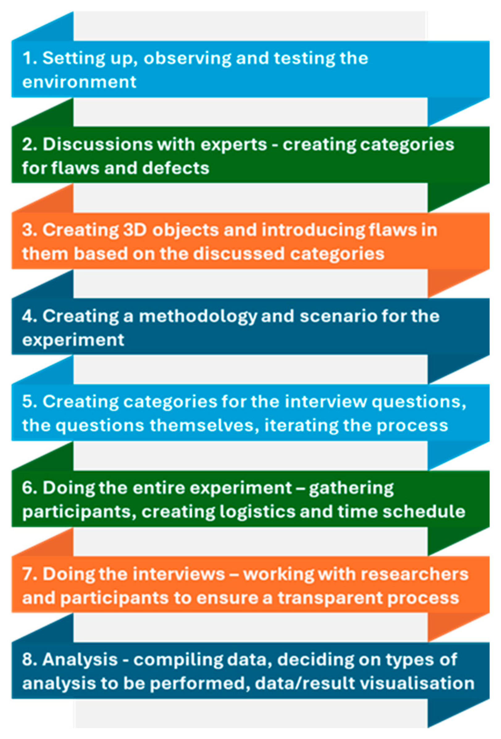
Figure 1 shows the complete methodology. Each of its steps are explained in detail below:
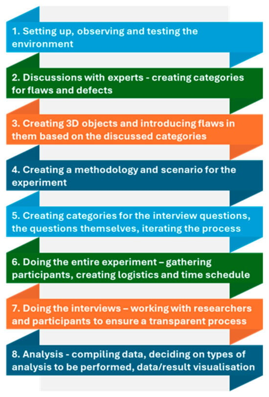
Figure 1.
General experiment methodology.
- 1.
- The display technologies were tested and observed, and the peculiarities of working with each display were discussed.
For example, at this stage, the stylus for the laptops with stereoscopic displays was deemed an unnecessary complication that would introduce a significant challenge for users and could influence experiment results, so it was removed, and a standard computer mouse was used. However, upon further testing with the pilot participant, it was deemed a practically insignificant problem that required a demonstration for a few seconds per participant. Thus, it was decided to keep the stylus and instruct the participants on its use. There was one pilot participant whose role was helping to streamline the entire experimental process. The person chosen for that pilot role was within the 31 to 40 years age range, had 10 years of experience in the field of IT with a wide range of practical experience, and had an average experience in working with 3D modeling. The participant was deemed appropriate to recognize eventual problems with the visualization methods we deployed. Additionally, other more experienced researchers were consulted about other improvements in the process. Their suggestions were considered and complied with, but they themselves were not participants in the experiment, as they would have been biased.
For the holographic display, the workstation was standardized to look like the other workstations present in the experimental room to prevent unnecessary confusion of the users, which could influence the results. In practice, this resulted in a traditional environmental setup, using a wireless mouse and a chair near one of the tables in the room.
The software used was the same or similar in terms of object manipulation between all the workstations. An online 3D viewer was used for two of the workstations, but the stereoscopic workstation included only the compatible stereoscopic viewer—the effects could be achieved only in its own included software.
- 2.
- Categories of 3D object defects were discussed and decided on by consulting experts in the field of mechanical engineering
The main defect types that were discussed were cosmetic, functional, tool-specific, manufacturing-specific, damage (due to wear and due to applied external force), and incompatibility with standard mechanical engineering principles. As the supplier for the objects was an expert in the field, they were consulted heavily on the different defects and their introduction and classification in each of the 3D objects.
- 3.
- Creating 3D objects
Three-dimensional scanning was considered in order to supply more realistic results, as the purpose of this study was to find imperfections that may affect the results of any such process through the introduction of defects or artifacts. The practical limitations of that, however, led to the use of preexisting mechanical engineering parts. Defects were introduced in those objects; afterwards, they were exported in STL and OBJ file formats.
- 4.
- Creating a scenario for the experiment (described in detail in a separate section in this paper)
- 5.
- Creating and categorizing questions, fit for further analysis
We created categories of questions based on the types of errors and defects in the objects, the specialization of participant groups, the number of technologies used, and the 3D object types. We brainstormed and discussed questions for each category in an iterative way, reaching a satisfactory set of questions.
- 6.
- Performing the experiment
This was mainly a logistical issue of finding enough qualified specialists for each participant category, creating a schedule to follow for both participants and researchers, and handling various peculiarities during the experiment itself (such as swapping the workstation and object order to negate random factors as much as possible.)
- 7.
- Performing the interviews
We arranged a group of researchers to accommodate each participant and interview them after they had completed the experiment. A rotation of researchers was assured in order to eliminate bias and minimize mistakes due to repetition or distraction.
- 8.
- Compiling data and deciding on types of analysis that must be performed
We computerized all the gathered data, classified the answer types to the interview questions, and using analytical methods for reliability, including Cronbach alpha for normal distribution; one-sample Kolmogorov–Smirnov test; and for descriptive statistics, mean and standard deviation. We discussed how to visualize the data in the best possible way for other researchers to gain sufficient understanding and value from the experiment, assuring reproducibility of the experiment as much as possible.
The split-half reliability method was also considered for testing survey reliability, but Cronbach’s alpha was chosen as a more suitable method for the analysis due to the bias the split of the data could introduce [21]. The Kolmogorov–Smirnov test was chosen over the Shapiro–Wilk test in the SPSS 26 analysis process because the data did not meet the assumptions of normality that the Shapiro–Wilk test requires. The null hypothesis chosen was that the data were normally distributed. The hypothesis was rejected for the entire dataset, which necessitated the analysis of descriptive statistics for the standard deviation and the mean for each question category.
2.1. Experiment Scenario
The experiment scenario was developed to ensure a transparent, robust, and invariable experimental process.
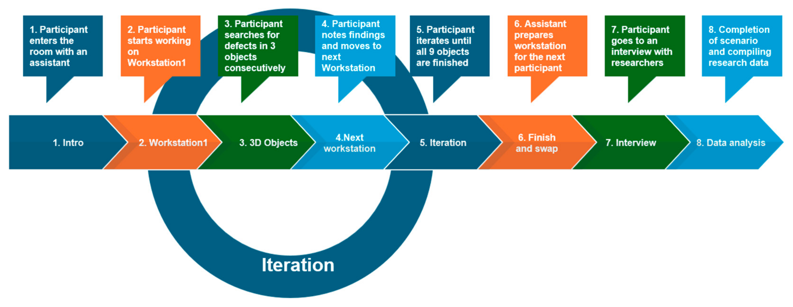
Figure 2 displays the chosen experiment scenario. Each of the steps in this scenario is explained in detail below:
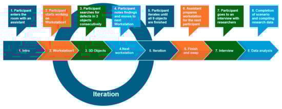
Figure 2.
Experiment scenario.
- The participant enters the room along with a researcher.
The role of the researcher was only to help the participant track time with their chronometer for each object and clarify any workstation questions that arose. The researcher was not an expert in the field of the 3D objects in order to ensure no bias was present. Instructions were printed on paper and given to the participant. Only one participant worked in the experiment room at a time. Although this required more time, it led to better results that would be isolated from outside influences as much as possible.
- 2.
- The participant starts working at a workstation (the researcher shuffles the order of workstations and objects for each of the participants).
There were three workstations in total: one with a normal monitor (the “control” group), and two experimental workstations with each of the other visualization technologies—a glasses-free stereoscopic display laptop and a front projection holographic simulation.
- 3.
- The participant starts working with three 3D objects. The researcher shuffles their order for each participant.
Each workstation had all nine objects, but only three were provided for each participant. It was crucial to rotate through all the objects for all the workstations to ensure minimal outside factors that could influence the experimental results. The workstations were set up with similar software to ensure as little interference based on technological peculiarities as possible. The only exception was the stereoscopic workstation, as it was impossible to use non-compatible software with it. The choice for the other two workstations was made with that in mind to find the most similar environments.
- 4.
- The participant finishes finding defects and writes their findings in the provided template.
The researcher notes the time it took the participant to finish finding the defects in each workstation using a chronometer. The accompanying researcher gives the participant a template that has the different projections of each 3D object in turn. The participant is instructed to circle the defects that they have found using a marker and write a short description for each of them using a pen.
- 5.
- The participant moves to the next workstation and thus passes through all three workstations and all nine of the 3D objects.
This is a standard iterative process that ensures all objects and technologies are visited; a repetition of the previous steps until completion.
- 6.
- The participant is escorted out of the experiment room and led to the interview room.
The researcher closes the files on each workstation and presents the next three objects.
- 7.
- An interview is conducted between a researcher and the participant. A short survey is completed.
- 8.
- The scenario is completed and the participant’s experiment results are compiled. Possible improvements are discussed.
In order to ensure less interference by outside factors such as light, the glass windows and the glass door panels were covered using black foil. The aim was to achieve almost complete darkness for the hologram workstation light condition recommendations. Several photos of the room with each experiment workstation, as well as the experiment environment, can be seen in Figure 3.
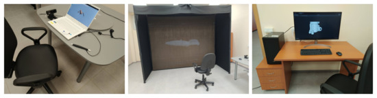
Figure 3.
From left to right, workstations 1, 2, and 3.
Figure 3 shows each workstation for each of the three display technologies. Workstation 1 is the stereoscopic display laptop, workstation 2 is the holographic simulation display, and workstation 3 is the control workstation—a normal computer.
The hardware specifications can be seen in Table 1. Workstation 1 is a stereoscopic glasses-free laptop that comes with a stylus (a pen that helps manipulate 3D objects within the native environment). Workstation 2 includes a PC that sends the image to a powerful projector, which illuminates a display with silver-infused threads. The setup also includes side-covers that help eliminate direct light coming from other directions. Workstation 3 is a PC with a large display. Specifically, for workstation 2, room modifications were needed in order to achieve better results.

Table 1.
Workstation hardware specifications.
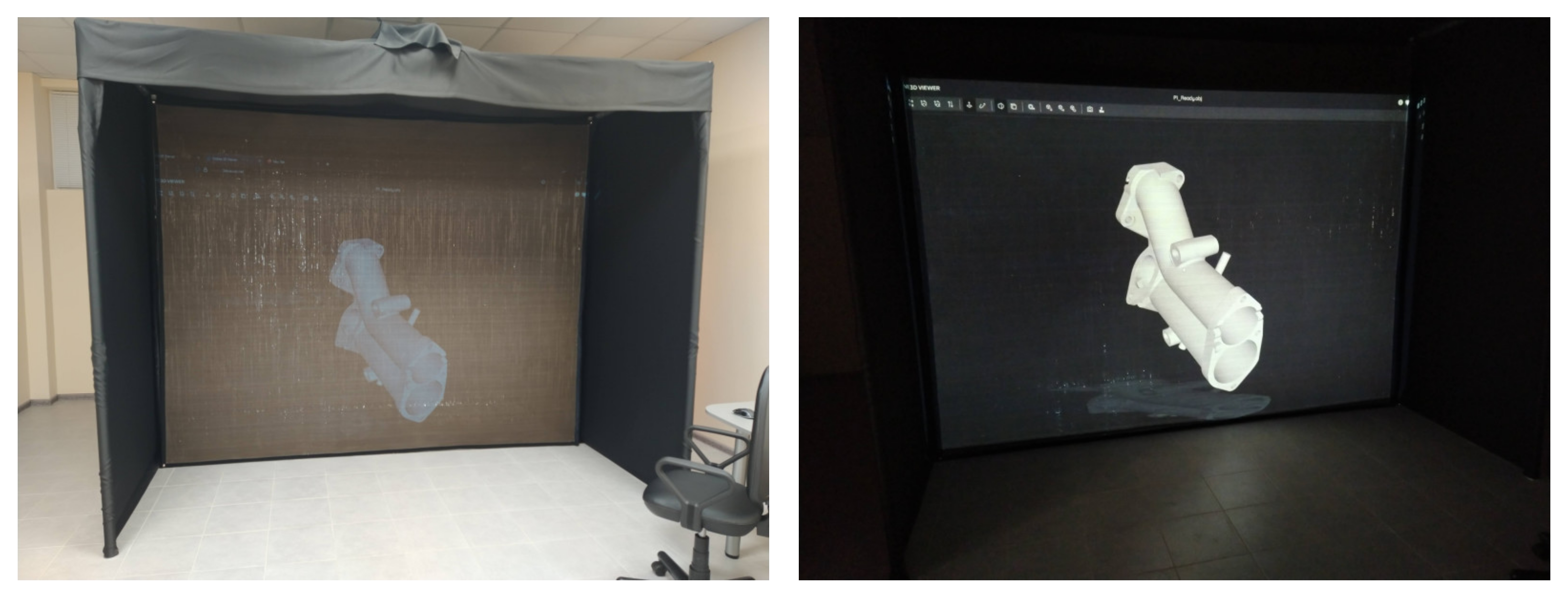
Figure 4 shows the room light insulation, as well as the difference when light is present for workstation 2. The degree to which light affects the experience of working with workstation 2 is apparent, and that made the modifications to the room a necessity.

Figure 4.
Workstation 2 with comparison of lights on and off, achieving the desired holographic effect.
Figure 5 shows some of the participants working on each of the workstations. During the experiment, a small USB-powered lamp was installed near workstation 2 in order to help the participants mark the defects on their paper template after they finished each of their object defect detections. The participants were always asked if they wanted the lights on during the marking process, but most chose to work in the dark, as the light level difference took time to get used to.
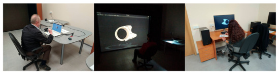
Figure 5.
Left to right: scenes of workstation 1, workstation 2, and workstation 3.
2.2. Software Choice
The software that was used to visualize the 3D objects for workstations 2 and 3 was the same—3Dviewer.net—to ensure uniformity and ease of use. In order for workstation 1’s stereoscopy effect to work, its own proprietary 3D viewer was used (Studio A3, version 5.2.0). Other options included Blender 3.5.0, AutoCAD 24.0, and SolidWorks 2024, but their complexity and the plethora of functionalities they provide were evaluated to introduce too much noise in the experiment results, so a simple solution was found. Microsoft Paint 3D was also considered, as it provides an effective method to mark the defects directly on the object in its native 3D view. However, workstation 1’s stereoscopy did not work there. This necessitated the use of projections printed on paper for the users to mark their results.
2.3. Defect Description
The artificially introduced defects in the CAD models are the crucial part of the conducted experiment. They should reliably reveal the capabilities of the studied screen technologies, being different in size, types, and position, as well as typical for the 3D models in mechanical engineering.
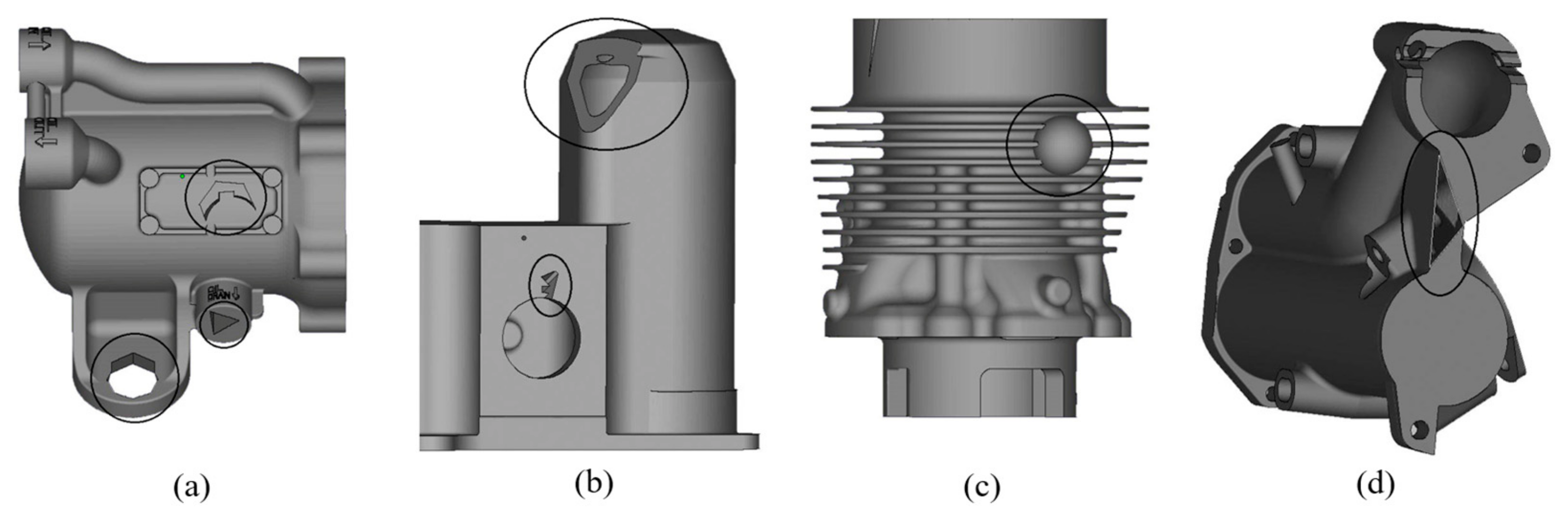
Examples of the chosen types of defects, marked with circles in Figure 6, are as follows:
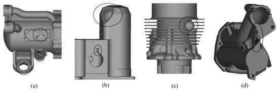
Figure 6.
Types of defects: (a) cutting out, (b) cropping, (c) insertion, (d) missing triangle.
- Cutting out: It may result in unacceptable or strange perforation like a hole in some area (Figure 6a).
- Cropping: The resulting shape is irregular and is illogical for a professional (Figure 6b).
- Insertion: The additional geometric element is functionally unacceptable and clearly redundant (Figure 6c).
- Missing triangle: Typical for 3D printing, this looks like a gap that exposes the inside of the shell (Figure 6d).
The size of each defect is classified as large, medium, or small compared to the part’s volume:
- Below 1% is small.
- Between 1% and 5% is medium.
- Above 5% is large.
The total number of part models is 10. The objects are numbered from 1 to 10. Part number 1 is used for the introduction phase, and others are numbered from 2 to 10 in the following text. There are between 4 and 6 defects in each model, which are randomly distributed. The type of defect, size, recurrence, and presence are summarized in Table 2.
Table 2.
Distribution of defects in the CAD models.
A form shown in Figure 7 is presented to each participant during the introduction phase of the experiment. A detailed description of possible defects and short instructions are also presented. The goal is to familiarize the person with the type of defect, upcoming experiment, and completion of a similar template for each of the parts.
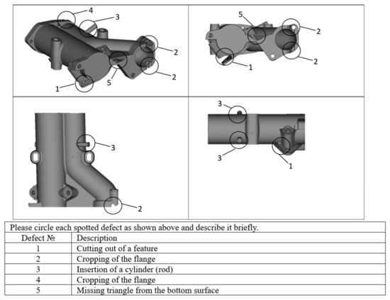
Figure 7.
Example of a completed form. A similar template is given for each separate 3D object.
2.4. Survey Composition
The complete survey composition is shown in Table 3. The Brook’s system usability scale [22] was considered, but a simplified version of the NASA method’s categorical distribution [23] was helpful to construct the survey.
Table 3.
Survey questions, their categories, and answer types.
The interview question classifications can be seen in Table 3 (answer types are as follows: MC = multiple choice, OA = open answer, LIKERT = Likert scale).
Most of the questions (34 out of 42) required answers that could be placed on a Likert scale. The rest (8 of 42) had either a multiple choice category or an open answer. This helped the research team to have an easy-to-understand metric to decide the likely outcomes of the experimental results during the process itself. The idea of in-depth qualitative research assumes that the participant number is enough to ensure data validity [24,25]. This is in stark contrast to quantitative research, where the participant number is assumed to be high enough to be representative of an entire population. Successful qualitative studies are available in different fields; for example, psychology [26], medical diagnostics [27,28,29], and statistics and interview research [30,31]. The format of this survey was inspired by sustainability [32] and good practices in higher education [33].
To reach data saturation for focused qualitative research, statistically, 30 people were considered enough for the current research, according to the referenced sources.
Due to the nature of the experiment, as well as the participant categories, it is difficult and time consuming in practice to find people in these categories (specialists in their own field that have a good amount of experience but are currently in the active workforce). One of the main reasons for this difficulty is the logistical problem of finding timeslots and organizing both participants and researchers due to their schedules.
After the pilot participant completed their work, several changes were made, most of them concerning the number of questions in the survey. During the interview with the first and second participants, almost half of the initial questions were deemed unnecessary, having duplicate meaning, or lacking clarity. The conversations during the interviews helped to streamline the survey questions, refining the final version presented in this paper.
The reliability of the questionnaire was assessed using Cronbach’s alpha, a measure of internal consistency. The survey was deemed acceptable with a value of 0.783 for Cronbach’s alpha. It was estimated that the survey statistical data were of appropriate quality for the experiment [34]. A conclusion can be made that this survey was reliable.
The inter-item correlation in Table 4 helps us to recognize whether the questions were strongly related to each other. A high coefficient of correlation signifies that the survey questions had similar or duplicate meaning. After the SPSS analysis, 8 out of 561 pairs of questions were found to have a high correlation coefficient—above the absolute value of |0.7|, which was 1.43% in total. For the second category, the results were average to high (absolute values between 0.4 and 0.7), including 126 out of 561 pairs, which is 22.46%. A total of 76.11% of the questions had a weak correlation (absolute values below 0.3); therefore, it can be concluded that the survey was successful in its purpose of gathering relevant information from the participants. A conclusion can be made that the gathered survey data are reliable.
Table 4.
Inter-item correlation table. Legend is below the table.
2.5. Participants
It should be noted that there were five people with a significant amount of experience working with 3D projections.
The participant categories are shown in Table 5. The target group of participants was defined as mainly working adults in their prime working age, due to the aim of this study to explore whether the display technologies would be beneficial for this category of people. Most of the participants were highly qualified professionals, well-educated, or people with an enormous amount of practical experience.
Table 5.
Participant categories and reasoning for the choice of participant for each category.
It should be noted that no one from the research team was included as a participant in the experiment in order to ensure the integrity of the data.
A detailed statistical distribution for the different categories of participants is shown in Figure 8. It was concluded that the participant age groups, gender, field of work, and experience in that field of work are sufficiently representative of the current qualitative study.
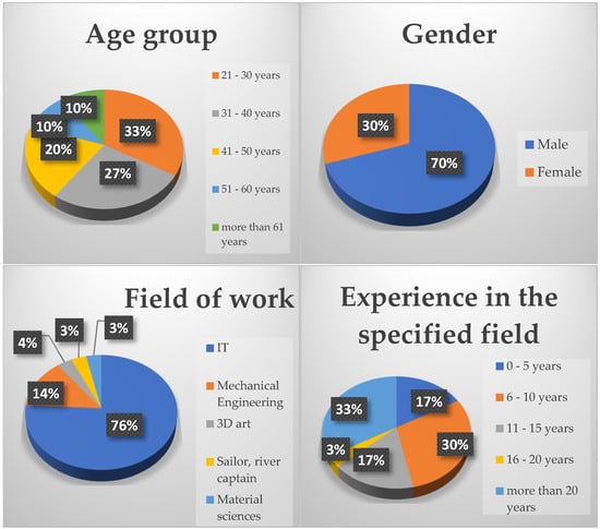
Figure 8.
Participant statistical distribution.
3. Results
The collated experiment results of all the participants can be seen in Table 6.
Table 6.
Collated experiment results per workstation.
The “Times done” row for each workstation is marked with a different color if it is deemed to be below the threshold of 6. It must be noted that the data are variable enough that such instances do not influence them in a significant manner. It can be concluded that the data gathered from the experiment are reliable for conducting qualitative research.
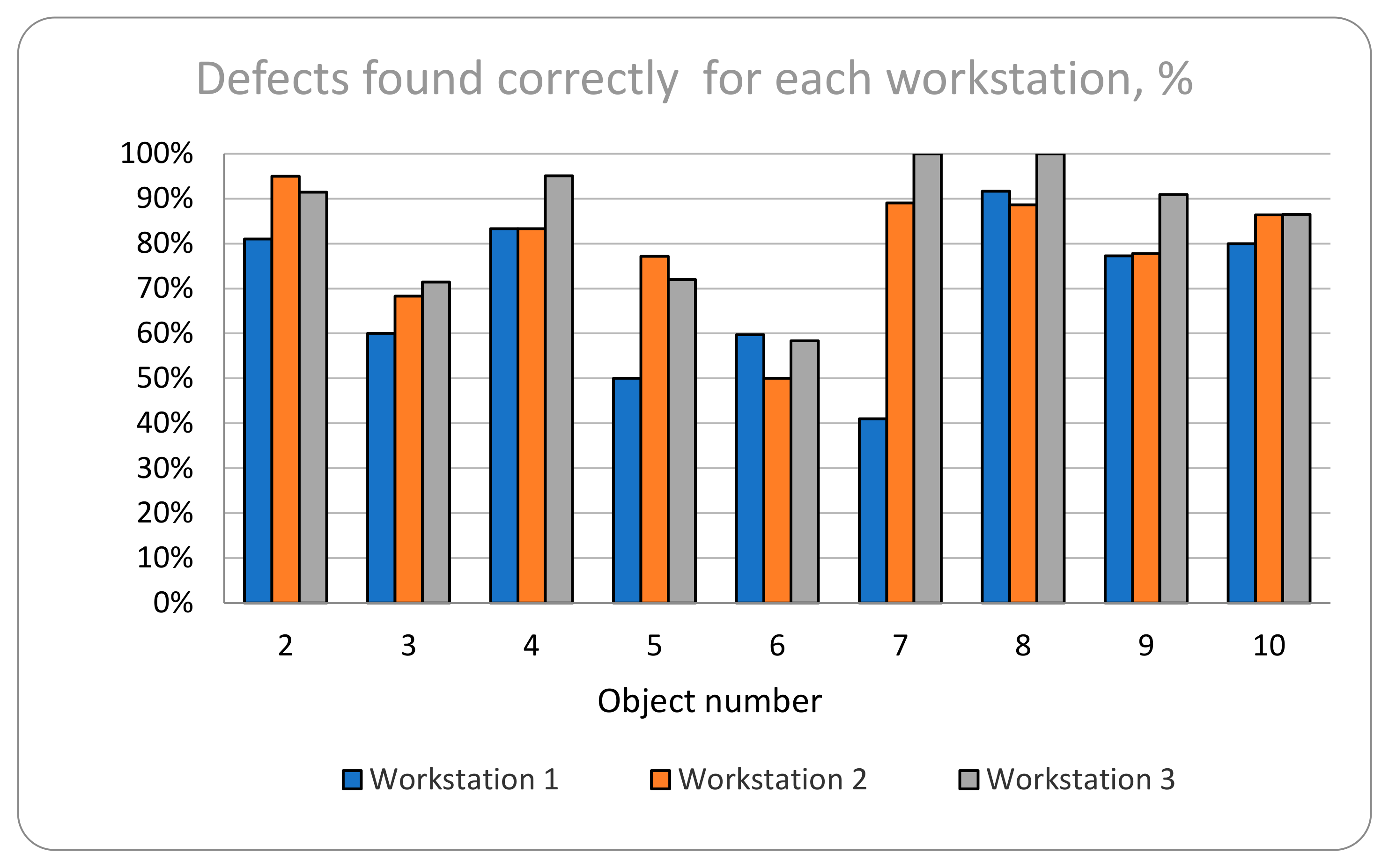
Figure 9 displays the distribution of correctly found defects in each workstation, per object. workstation 1 in general has the least amount of correctly found defects, as only with object 6 does the result surpass the control workstation 3, and that is only by a small margin. The same is valid for workstation 2, although there are consistent results showing a closer gap between the results there and the control workstation 3. It can be concluded that the control workstation 3 has consistently better results for defect detection in the experiment.
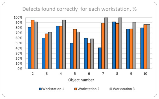
Figure 9.
Distribution of correctly found defects in each workstation for each object.
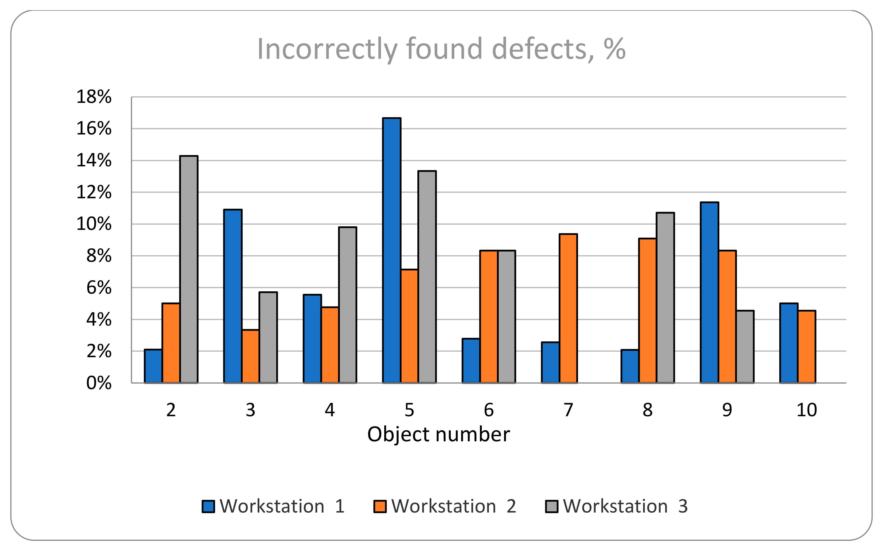
Figure 10 displays the percent of incorrectly found defects in each workstation per object. The mistakes are calculated as a percentage when compared to the total number of defects for each object. The entire category can be seen with its absolute collated numbers in Table 6. An observation can be made that there is no strong relationship between the workstation and the number of mistakes made. These results are possibly related more to the lack of sufficient expertise required to recognize whether a feature is a defect or not; hence, that leads to the current distribution.
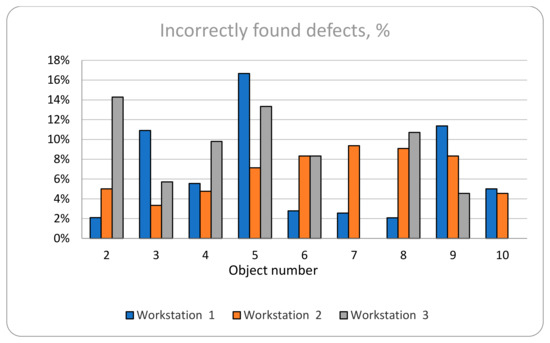
Figure 10.
Distribution of incorrectly found defects in each workstation for each object.
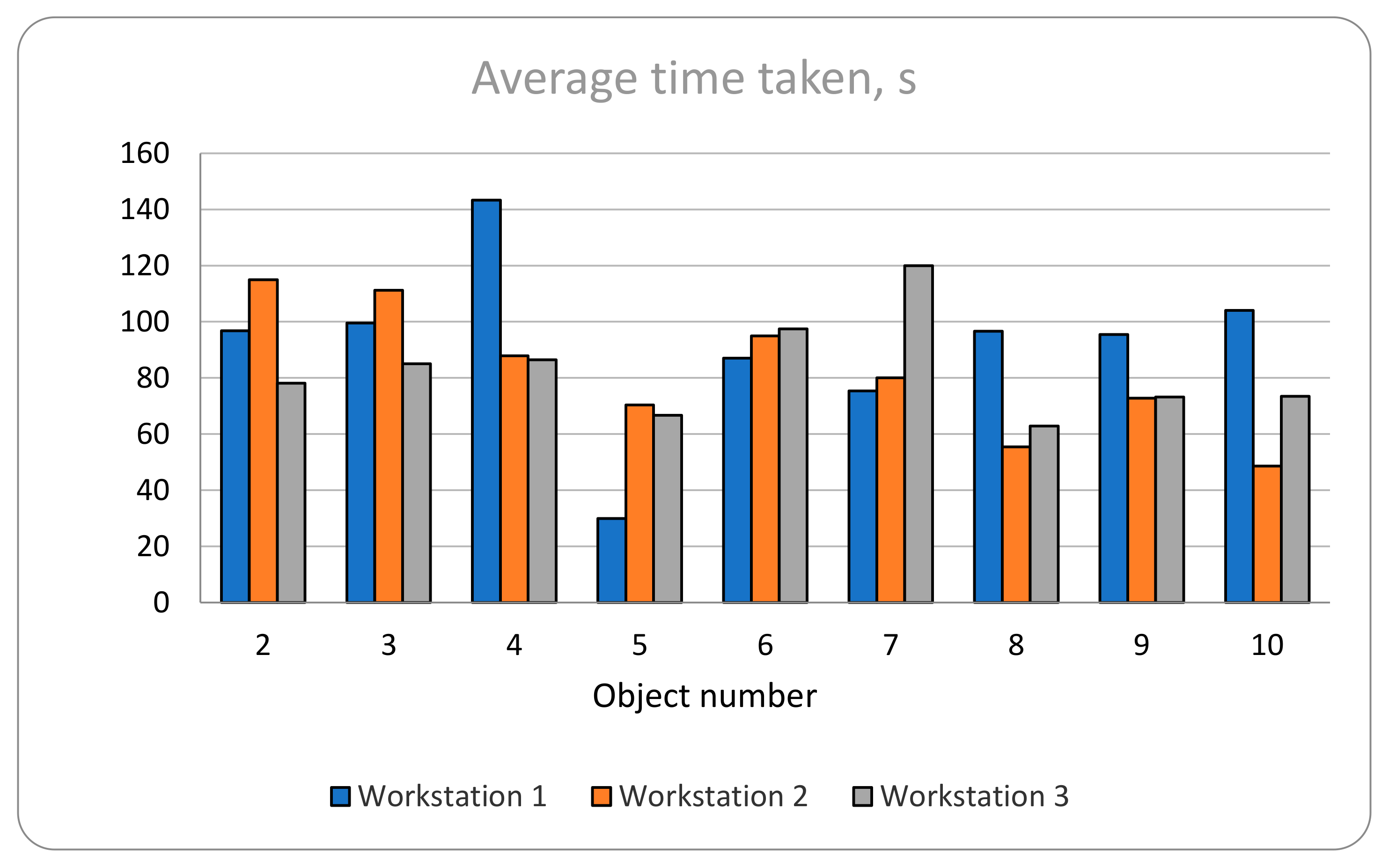
Figure 11 shows the measurement of the time taken for each object in each workstation. The results show consistently competitive results for all three workstations. This was also observed during the experiment itself—when the participants became accustomed to the workstations, their work became consistently fast. There were only small differences in the time it took each participant to locate defects in each separate workstation, but it must be noted that the most time it took was for workstation 1. It can be concluded that the time it took had little meaningful difference for defect detection for workstations 2 and 3, while workstation 1 required more time for objects 4, 8, 9, and 10.

Figure 11.
Average time (in seconds) it took for each object in each workstation.
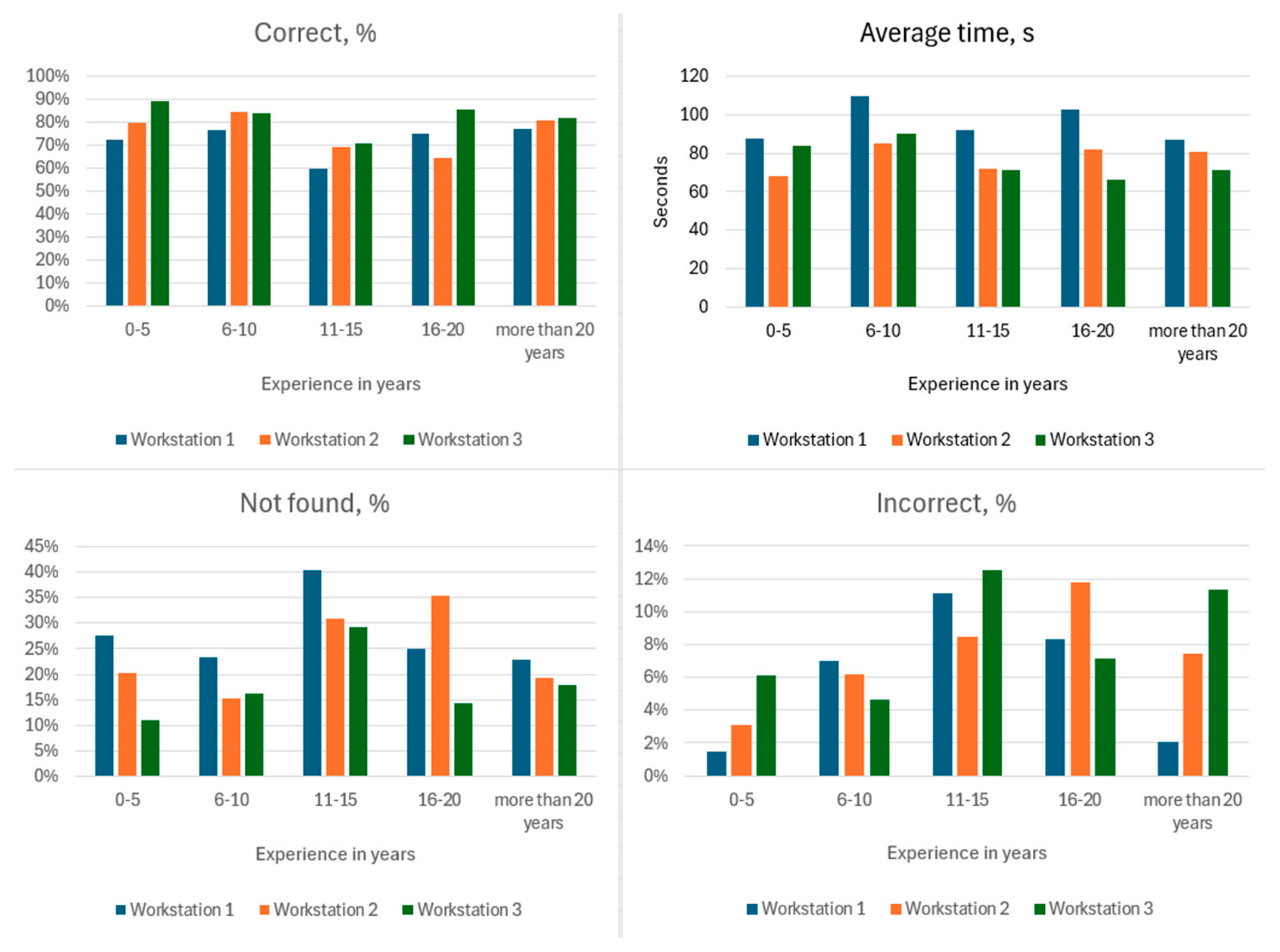
In Table 7 and Figure 12, the collated data for each category of participant experience can be observed. The data show that people with less experience in the field mark fewer defects incorrectly. The most- and least-experienced people made the least mistakes (marking an incorrect defect) on workstation 1. On average, the time it took to find the defects for each age group was the same for all age groups on all workstations. Workstation 1 required the most time for all groups, while workstations 2 and 3 were competing for second place depending on the age group—less-experienced participants required less time in workstation 2, while more-experienced participants worked the fastest on workstation 3. It can be concluded that in terms of finding the correct defects, the best workstation was the third—workstation 3.
Table 7.
Results for each participant experience category.
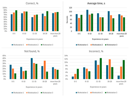
Figure 12.
Results for each category of participant experience.
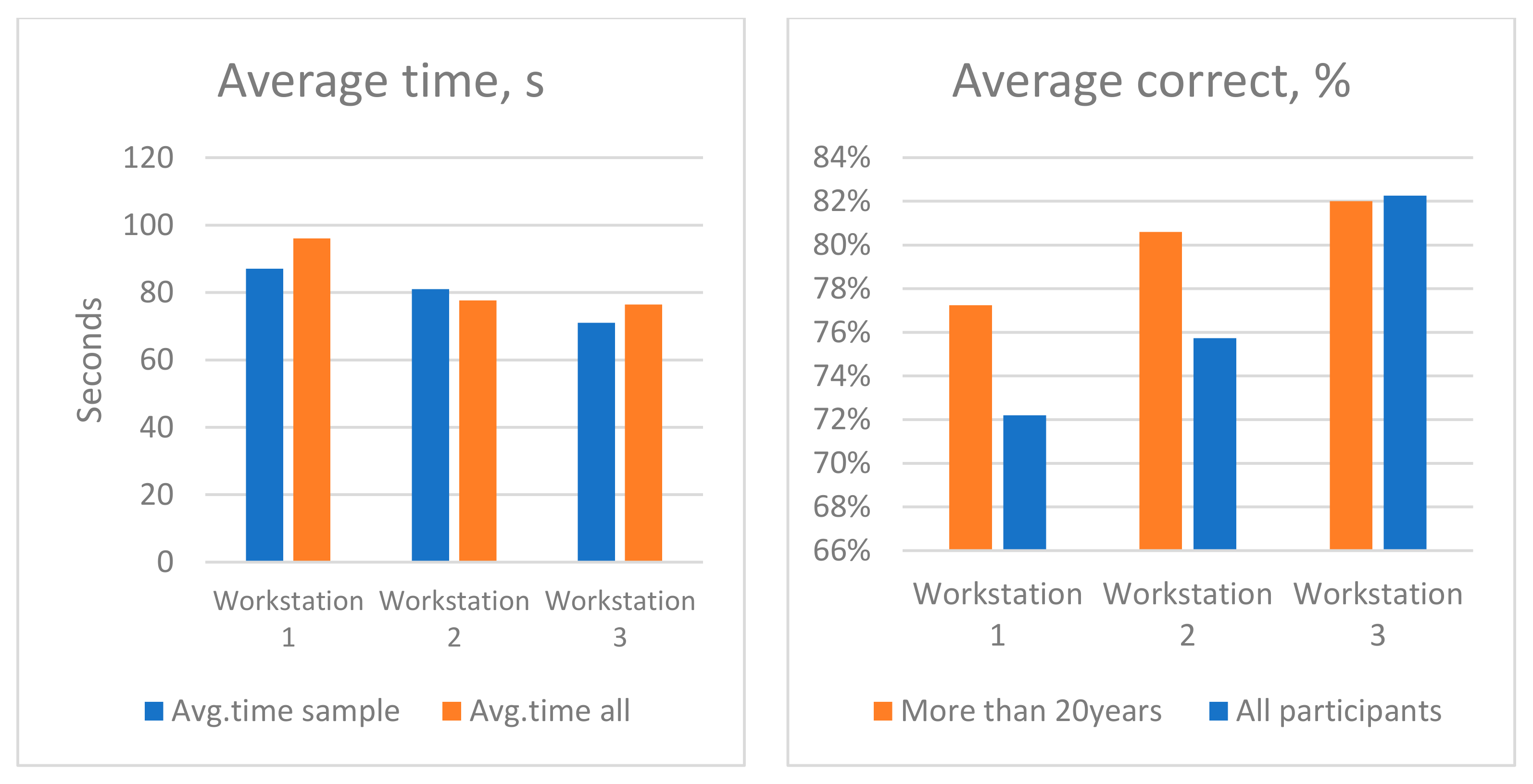
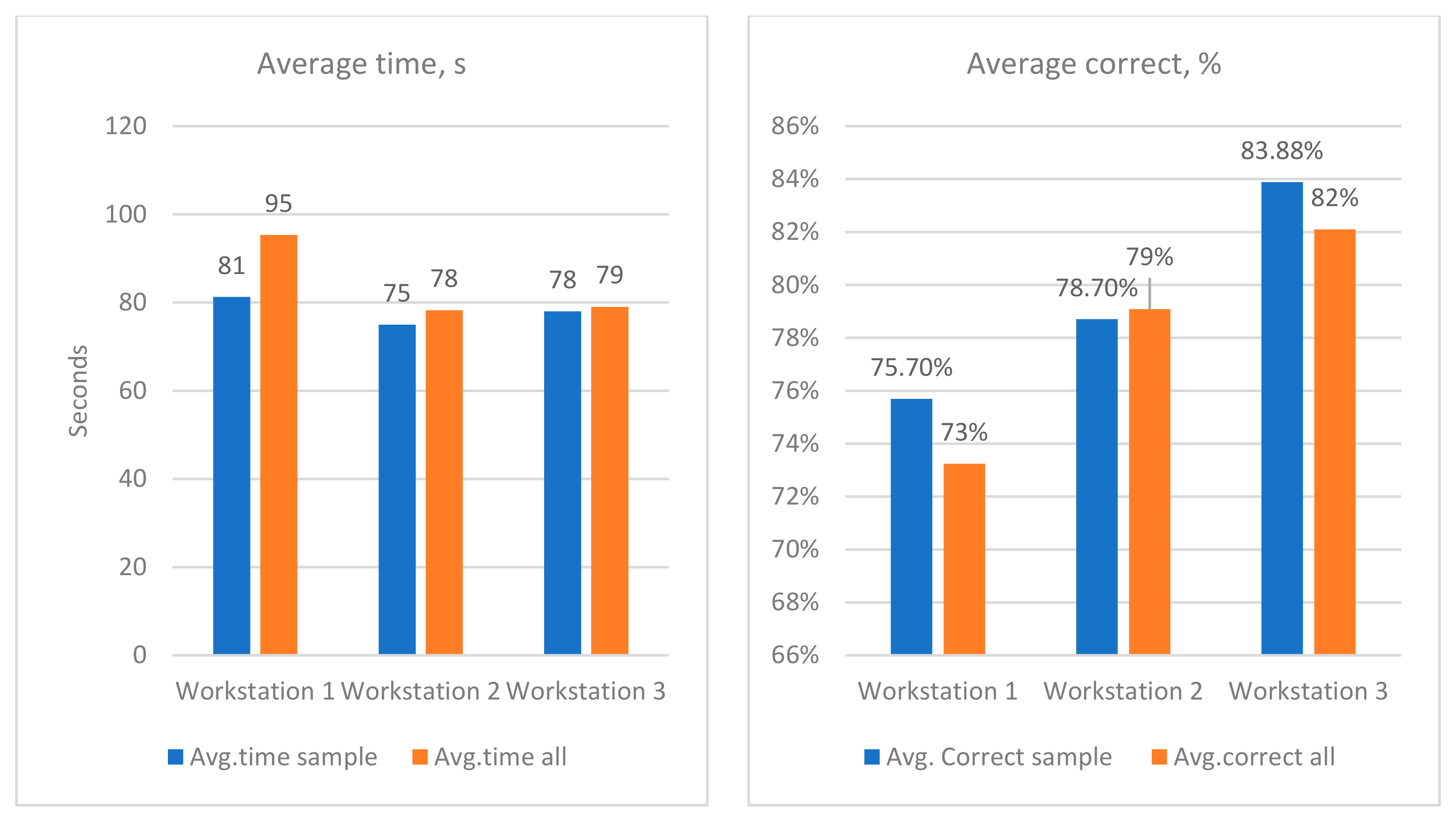
An observation was been made that most participants with work experience were consistent in their time taken to find the object defects, and their average percentage of correctly found defects followed a smoother distribution than the collective average. This can be observed in Table 8 and Figure 13—these include the sample data compared to the average results of all the participants.
Table 8.
Results of experienced (20+ years) participants compared to average results: % correctly found defects and average time taken to complete their work.
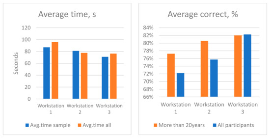
Figure 13.
Chart view of performance of participants with more than 20 years of experience in their field (sample) compared to the average result of all participants.
Survey Results
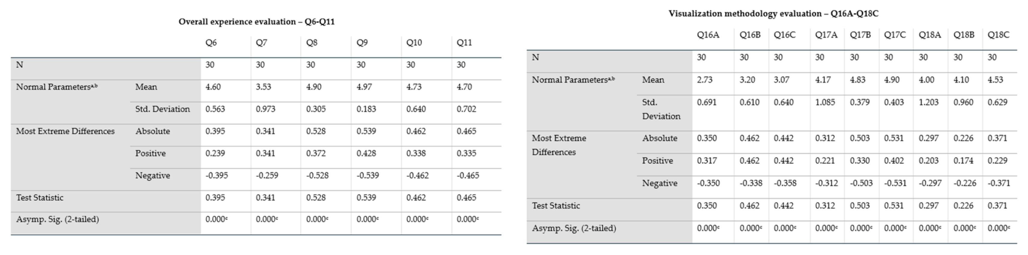
The survey results were tested for normalization using the Kolmogorov–Smirnov one-sample test for each question category. The results are shown in SPSS tables, including the descriptive statistics data, which were analyzed afterwards.
The answers from every relevant category of questions were subjected to the Kolmogorov–Smirnov one-sample test, as seen in Figure 14. The test results were statistically significant due to the value of “p”–“Asymp. Sig.” being below 0.05 for every category. The K-S Statistic (D) parameter displays how much the sample correlates to the theoretical distribution. A value between 0 and 1 indicates a perfect match between them.

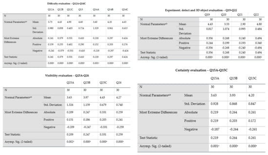
Figure 14.
Results from normalization analysis for each question category in the survey based on the Kolmogorov–Smirnov one-sample test. The superscript “a” signifies that the analysis was made with the assumption that the test distribution is normal, while superscript “b” shows that the values were computed directly from the experiment dataset.
Analyzing the results by category:
Overall experience evaluation (Q6–Q11)—all questions’ results, with the sole exception of Q7, have a mean value that is close to the high end, showing the participants positive reception towards the experiment. The standard deviation for Q6, Q7, and Q10 is relatively low, and for Q8 and Q9, it is low. This indicates that the answers are grouped around the mean value.
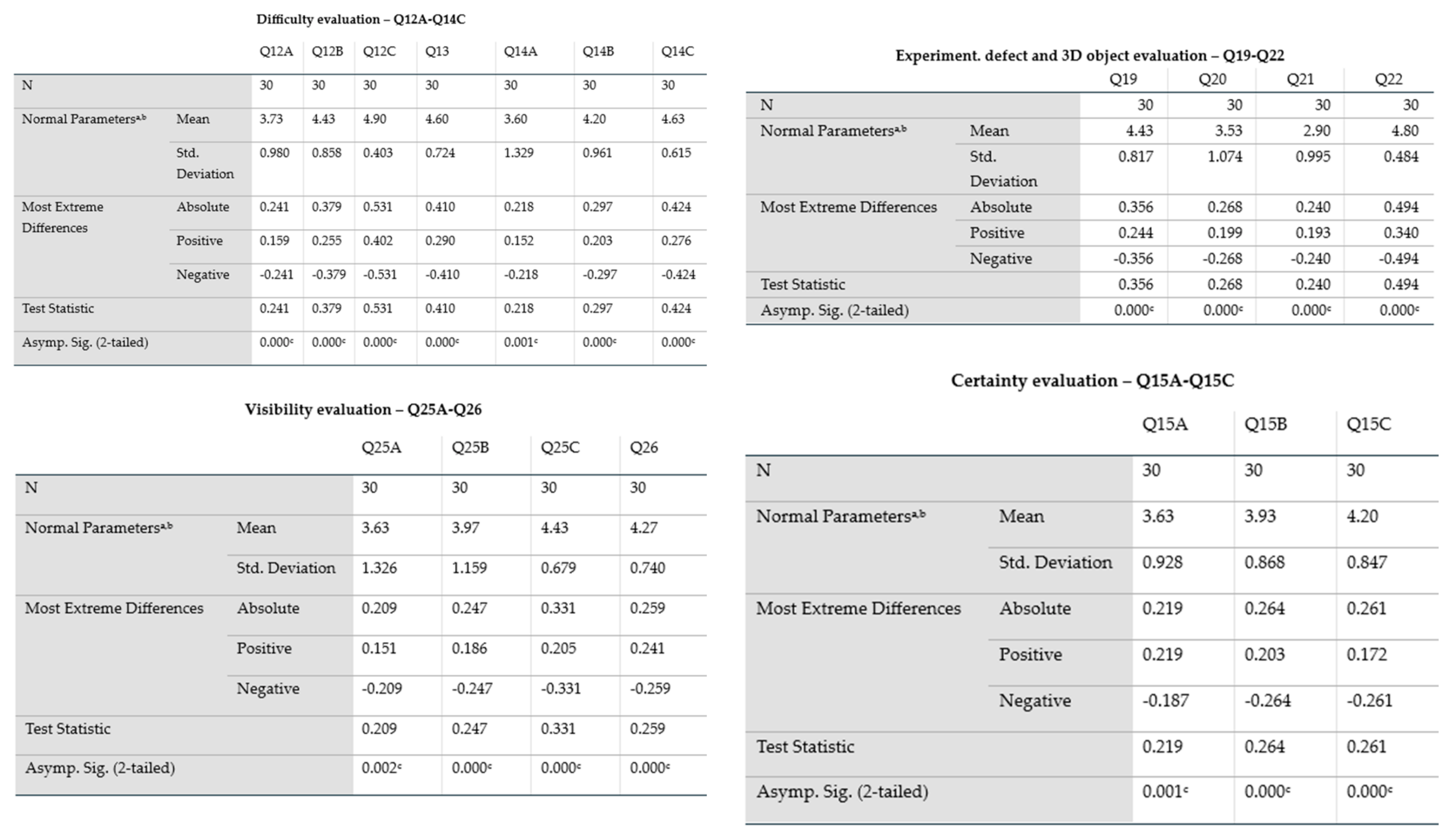
Difficulty evaluation (Q12A–Q14C): The mean value for Q12B, Q12C, Q13, and Q14 is high, which indicates that participants “felt” working with the workstation was easy, and they did not encounter difficulties while searching for defects. The standard deviation for Q12A, Q12B, Q13, Q14B, and Q14C is relatively low, and for Q12C, it is low. Along with the high mean value, this indicates that the assumed easiest workstation to work with was workstation 3. This was one of the main reasons to determine the correlation between the participants, which indicated the ease of use of the workstations and their actual experiment results. These data were used to check whether their perception about the difficulty (noted in the survey) was proven by their results in the experiment. The answers to this category of questions are grouped around the mean value, with the sole exception of Q14A, where the answers are deviating more.
Certainly evaluation (Q15A–Q15C): The mean value for all questions is around choice number 4, which indicates that the participants felt relatively confident in their defect identification. The standard deviation for all three questions is relatively low and shows that the answers are grouped around the mean value.
Visualization methodology evaluation (Q16A–Q18C): The mean value is high for Q17B, Q17C, and Q18C, which shows that most of the participants found the visualization methodology very intuitive and accurate. Q17A, Q18A, and Q18B have their mean around choice 4, and this indicates that some of the participants found the visualization methodology relatively intuitive and accurate. The mean of Q16A, Q16B, and Q16C was around 3—in the middle—which signifies that the participants evaluated the size of the defects as normal: neither too big nor too small. This is important, as these answers also indicate the participants’ ability to quickly grasp how to work with the workstations and manipulate 3D objects in a way that will render the size of defects irrelevant, at least for the three workstations in this experiment. The standard deviation for Q16A, Q16B, Q16C, Q18B, and Q18C showed an average level of variance. Q17B and Q17C had low variance, and the mean value was the highest, meaning that the participants evaluated workstations 2 and 3 as being most intuitive to work with. Q17A and Q18A display a moderate deviation, which means there is a large variety of responses, meaning that workstation 1 (the stereoscopic laptop) received the lowest evaluation for “intuitive to work with” by the participants.
Experiment, defect, and 3D object evaluation (Q19–Q22): The mean value for the answers for Q19 was high, with an average deviation. Q20 had a mean value nearing 3, but it had a moderate deviation, indicating a higher variance in responses. The mean for Q21 was 2.90 and it had a moderate deviation, which shows that the participants did not see unique defects (defects that were present only once during the entire experiment). Q22’s deviation was small and the mean was high, which indicates that participant attention and interest during the experiment remained high.
Visibility evaluation (Q25A–Q26): Q25A, Q25B and Q25C had means that varied from 3.63 to 4.43, indicating that the objects were visible from most angles for the participants. The overall visibility, Q26, was evaluated as relatively good. The deviation in questions Q25A and Q25B was larger, indicating that some of the participants experienced visibility-related issues in workstations 1 and 2.
Feedback (Q27 and free answers in Q28): Nearly all the participants were fully immersed in the experiment and had positive feedback to share. The constructive criticism by the participants was directed at the technologies themselves and not the experiment. It must be noted that several participants were uncomfortable to different degrees during their work on workstation 1. During the interview discussion part (Q28), when asked whether they had an eye condition, it turned out that every person who had been uncomfortable had a varying degree of astigmatism or was of an advanced age. This must be taken into account when considering using this technology on a large scale, and more research on the topic must be carried out by medical professionals.
From the category for the difficulty evaluation, question Q12 was examined in detail (“How easy was the work during each stage of the experiment?” Q12A was related to workstation 1, Q12B to workstation 2, and Q12C to workstation 3). All participants who answered with 5 (that the workstation was extremely easy to work with) had their experiment results analyzed in detail in order to juxtapose their subjective view to their objective results. The number of each participant and their count by question can be observed in Table 9. The analysis of Q12 is of significant importance, as it is closely related to the main goal of this research.
Table 9.
Participants that selected the maximum value of 5, for questions Q12A, Q12B, and Q12C, respectively.
This slice of the participants’ results was collated in separate tables for closer analysis. Determining their level of success compared to the average of the entire participant population was the goal of this part of the analysis. Three similar tables were separately introduced for each workstation. The number of defects denotes all of the defects present in all of the objects that were presented to the participant at the workstation, where “correct” indicates the number of defects that were successfully recognized, and “not found” indicates the number of defects not found (the “correct” and “not found” together comprise 100% of the total number of defects). The number of incorrectly found defects is not a composite part of the entire number of defects, but rather things that were noted that were not effectively defects, but original parts of the functioning object. The results can be observed in the three following tables: workstation 1—Table 10; workstation 2—Table 11; workstation 3—Table 12.
Table 10.
A sample of participant experiment results for workstation 1 for those who answered that it was extremely easy to work with workstation 1.
Table 11.
A sample of participant experiment results for workstation 2 for those who answered that it was extremely easy to work with workstation 2.
Table 12.
Sample of participant experiment results for workstation 3, for those who answered that it was extremely easy to work with workstation 3.
For workstation 1 (Table 10), three participants (43%) had less than 70% correct and four (57%) had more than 70%.
For workstation 2 (Table 11), five participants (26%) had less than 70% correct and fourteen (74%) had more than 70%.
Figure 15 compares the average of the sample and the average of the entire participant population. It can be observed that fewest participants responded that workstation 1 was extremely easy to work with, and from their results, it can be concluded that they were faster and had more correct responses compared to the average. The same can be concluded for workstation 3. The averages for workstation 2, however, showed very close results between the average participant and the select sample size.
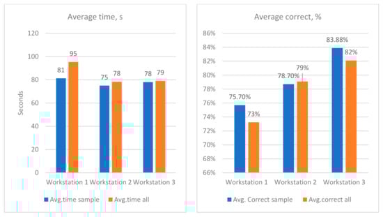
Figure 15.
Comparison between the average of the sample and the average of the entire participant population.
For workstation 3 (Table 12), two participants (7%) had have less than 70% correct, and twenty-six (93%) had more than 70%.
4. Discussion
Over the course of the experiment, it was concluded that the noise in the experiment environment was minimized as much as possible. In order to ensure as much impartiality as possible, each participant was uninformed about the nature of the study. There was a “trick” question in the survey about their “expectations”, Q7, and whether the experiment was as they expected it to be. The answers showed a satisfactory trend—most did not know what to answer, as they did not have any expectations, which confirms their own lack of prior information, and consequently any bias they might have had.
The types of defect and their numbers varied from object to object; hence, they were statistically insignificant, as the defects themselves were not the study’s main goal. This variation was intentionally decided in the beginning, in order to minimize pattern recognition by the participants—either the number or the type of the defect. One possible explanation of the result shown in Figure 9 is that using a large screen hologram results in fewer distractions in a limited light environment and helps with concentration. However, this is not enough to overwhelm preexisting experience on already adopted technologies. Another factor could be the resolution of the screen. This should be included in future research. The harsh change in light conditions in the environment could also contribute to the possible experiment result differences, although the questionnaire and interview results did not reveal this. During the discussions, the participants noted that they were more immersed in the task on workstation 2.
On the other hand, the practical limitations of workstation 2—screen size and light requirements—made it difficult to apply in practice. The difference in results is not significant enough to warrant widespread adoption.
Experiments that involve humans and their live performance are naturally subject to unpredictable and undefined influences. For this reason, several measures for consistency were taken:
- The exact following of the scenario (Figure 2) was supervised by the designated member of the research team.
- Over the course of the experiment, the surrounding noise in the room was minimized.
- In order to ensure objectivity, each participant was uninformed about the nature of the study.
Possible reasons for the results shown in Figure 12 and Figure 13 are overconfident behavior by more experienced participants, underestimating the task at hand due to familiarity with the technology. It took them more time to complete their tasks using the other newer technologies that they were less familiar with.
The average time it took for each participant to complete the experiment was around one hour. Although the researchers’ expectations were that this would be too long and taxing on everyone, according to the feedback, this was an acceptable time range, as no negative opinions were presented during the interviews. Most of the participants were surprised that an hour had passed by the time they finished the experiment, which leads to the conclusion that the time range was appropriate and the experiment was interesting to them.
5. Conclusions
In general, it is easy to come up with a conclusion on how useful a technology will be, based on common sense. This is a very dangerous line of thinking, however, because an unproven opinion has no weight. Thus, it is necessary to conduct an experiment (and in the best-case scenario, a series of both quantitative and qualitative experiments) in order to prove this view. In this case, the experiment had results that were unexpected by the creators, as the varying opinions on the different technologies led to serious considerations on the topic. Each different visualization method had its own positive and negative sides but applying it in practice helped us to further understand exactly how useful it would be in a given field.
After analyzing the data and combining them with the conclusions made during the experiment itself, taking into account all the participants’ feedback, responses, and opinions, it can be said with confidence that both technologies have a future, but the stereoscopic effect without using glasses must be heavily researched from the medical side before being applied to large groups of people. Medical staff were also considered for the experiment. Time constraints have necessitated that their feedback be separated in another paper, as the considerations for the 3D objects are of different categories, and the measurement of participant defect detection is fundamentally different from objects in the mechanical engineering field.
The conclusions about the experiment results were confirmed by both an objective method, experiment results, and a subjective one, survey answers. More-experienced participants were more consistent in their experiment results. The size and variation in the study group was deemed sufficient for the conduct of qualitative research. The sole 3D artist and the various engineers were chosen to validate the researcher’s thought process for the experiment and recognize if the experiment was executed correctly. They are mostly noted in the current research for display and completeness purposes. The survey data and questions were analyzed and found to be reliable. The answers were found to not be normalized and were biased towards positive. Younger participants and some of the older ones appreciated workstation 1 more, although it was, in general, more difficult to work with. The participants that were more confident during their quiz achieved better results in 2 of the 3 workstations (compared to the average of all participants). The different categories in the survey showed that an overwhelming majority of the participants were positive in their opinion both about the experiment and the technologies themselves. Most of the participants did not find it very challenging to perform the assigned tasks, meaning all technologies could be used for the purpose of finding defects in 3D objects. The short interview discussions after the completion of each experiment all concluded in a positive manner, and feedback was positive. Workstation 3—the control workstation—had the best participant results when finding defects. All workstations had similar results when it came to incorrectly found defects—the technologies themselves did not influence the mistakes that the participants made.
It can be concluded that this research was successful in reaching an answer to the research question, and that more similar experiments are necessary for different fields of study to explore the different possible applications of these types of display technologies.
Author Contributions
Conceptualization, V.K.; methodology, V.K. and E.M.; validation, V.K. and M.A.; formal analysis, V.K. and M.A.; investigation, E.M.; resources, V.K. and R.R.; data curation, V.K., E.M. and M.A.; writing—original draft, V.K. and M.A.; writing—review and editing, V.K., E.M., M.A., T.V. and R.R.; visualization, V.K.; supervision, V.K., T.V. and R.R.; project administration, V.K.; funding acquisition, V.K. and T.V. All authors have read and agreed to the published version of the manuscript.
Funding
This study was financed by the European Union—NextGenerationEU, through the National Recovery and Resilience Plan of the Republic of Bulgaria, project No. BG-RRP-2.013-0001-C01.
Institutional Review Board Statement
Not applicable.
Informed Consent Statement
Informed consent was obtained from all subjects involved in the study.
Data Availability Statement
The data are available upon request.
Acknowledgments
This study was financed by the European Union—NextGenerationEU through the National Recovery and Resilience Plan of the Republic of Bulgaria, project No. BG-RRP-2.013-0001-C01.
This publication was developed with the support of Project BG05M2OP001-1.001-0004 UNITe, under Operational Programme “Science and Education for Smart Growth”, by the European Union trough the European Structural and Investment Funds.
Conflicts of Interest
The authors declare no conflicts of interest.
References
- Petrov, P.D.; Atanasova, T.V. The Effect of augmented reality on students’ learning performance in stem education. Information 2020, 11, 209. [Google Scholar] [CrossRef]
- Aljumaiah, A.; Kotb, Y. The impact of using zSpace system as a virtual learning environment in Saudi Arabia: A case study. Educ. Res. Int. 2021, 2021, 2264908. [Google Scholar] [CrossRef]
- Zhou, Z.; Yang, Z.; Jiang, S.; Jiang, B.; Xu, B.; Zhu, T.; Ma, S. Personalized virtual reality simulation training system for percutaneous needle insertion and comparison of zSpace and vive. Comput. Biol. Med. 2022, 146, 105585. [Google Scholar] [CrossRef] [PubMed]
- Palumbo, A. Microsoft HoloLens 2 in medical and healthcare context: State of the art and future prospects. Sensors 2022, 22, 7709. [Google Scholar] [CrossRef] [PubMed]
- Kontogiorgakis, E.; Zidianakis, E.; Kontaki, E.; Partarakis, N.; Manoli, C.; Ntoa, S.; Stephanidis, C. Gamified VR Storytelling for Cultural Tourism Using 3D Reconstructions, Virtual Humans, and 360° Videos. Technologies 2024, 12, 73. [Google Scholar] [CrossRef]
- Lebamovski, P.; Gospodinova, E. Investigating the Impact of Mental Stress on Electrocardiological Signals through the Use of Virtual Reality. Technologies 2024, 12, 159. [Google Scholar] [CrossRef]
- Triviño-Tarradas, P.; García-Molina, D.F.; Rojas-Sola, J.I. Impact of 3D Digitising Technologies and Their Implementation. Technologies 2024, 12, 260. [Google Scholar] [CrossRef]
- Wu, Y.; Wang, Y.; Lou, X. A large display-based approach supporting natural user interaction in virtual reality environment. Int. J. Ind. Ergon. 2024, 101, 103591. [Google Scholar] [CrossRef]
- Chao, C.J.; Yau, Y.J.; Lin, C.H.; Feng, W.Y. Effects of display technologies on operation performances and visual fatigue. Displays 2019, 57, 34–46. [Google Scholar] [CrossRef]
- Solari, F.; Chessa, M.; Garibotti, M.; Sabatini, S.P. Natural perception in dynamic stereoscopic augmented reality environments. Displays 2013, 34, 142–152. [Google Scholar] [CrossRef]
- Pi, D.; Liu, J.; Wang, Y. Review of computer-generated hologram algorithms for color dynamic holographic three-dimensional display. Light Sci. Appl. 2022, 11, 231. [Google Scholar] [CrossRef] [PubMed]
- Kim, J.; Gopakumar, M.; Choi, S.; Peng, Y.; Lopes, W.; Wetzstein, G. Holographic glasses for virtual reality. In Proceedings of the ACM SIGGRAPH 2022 Conference Proceedings, Vancouver, BC, Canada, 7–11 August 2022; pp. 1–9. [Google Scholar] [CrossRef]
- Johnson, B.K.; Naris, M.; Sundaram, V.; Volchko, A.; Ly, K.; Mitchell, S.K.; Acome, E.; Kellaris, N.; Keplinger, C.; Correll, N.; et al. A multifunctional soft robotic shape display with high-speed actuation, sensing, and control. Nat. Commun. 2023, 14, 4516. [Google Scholar] [CrossRef] [PubMed]
- Geng, J. Three-dimensional display technologies. Adv. Opt. Photonics 2013, 5, 456–535. [Google Scholar] [CrossRef] [PubMed]
- Ivanova, G.; Ivanov, A.; Zdravkov, L. Virtual and augmented reality in mechanical engineering education. In Proceedings of the 2023 46th MIPRO ICT and Electronics Convention (MIPRO), Opatija, Croatia, 22–26 May 2023; IEEE: Piscataway, NJ, USA, 2023; pp. 1612–1617. [Google Scholar] [CrossRef]
- Waskito, W.; Fortuna, A.; Prasetya, F.; Wulansari, R.E.; Nabawi, R.A.; Luthfi, A. Integration of mobile augmented reality applications for engineering mechanics learning with interacting 3D objects in engineering education. Int. J. Inf. Educ. Technol. (IJIET) 2024, 354–361. [Google Scholar] [CrossRef]
- Koulieris, G.A.; Akşit, K.; Stengel, M.; Mantiuk, R.K.; Mania, K.; Richardt, C. Near-eye display and tracking technologies for virtual and augmented reality. Comput. Graph. Forum 2019, 38, 493–519. [Google Scholar] [CrossRef]
- Figueiredo, M.J.; Cardoso, P.J.; Gonçalves, C.D.; Rodrigues, J.M. Augmented reality and holograms for the visualization of mechanical engineering parts. In Proceedings of the 2014 18th International Conference on Information Visualisation, Paris, France, 16–18 July 2014; IEEE: Piscataway, NJ, USA, 2014; pp. 368–373. [Google Scholar] [CrossRef]
- Prathibha, S.; Palanikumar, K.; Ponshanmugakumar, A.; Kumar, M.R. Application of augmented reality and virtual reality technologies for maintenance and repair of automobile and mechanical equipment. In Machine Intelligence in Mechanical Engineering; Academic Press: Cambridge, MA, USA, 2024; pp. 63–89. [Google Scholar] [CrossRef]
- Johnson, P.; Harris, D. Qualitative and quantitative issues in research design. In Essential Skills for Management Research; SAGE Publications Ltd.: Thousand Oaks, CA, USA, 2002; pp. 100–116. [Google Scholar] [CrossRef]
- Field, A. Discovering Statistics Using IBM SPSS Statistics; Sage Publications Limited: Thousand Oaks, CA, USA, 2013; pp. 115–121. Available online: https://vlb-content.vorarlberg.at/fhbscan1/330900091084.pdf (accessed on 10 January 2025).
- Brooke, J. SUS—A quick and dirty usability scale. In Usability Evaluation in Industry; CRC Press: Boca Raton, FL, USA, 1996; pp. 4–7. [Google Scholar]
- Hart, S.G. Development of NASA-TLX (Task Load Index): Results of empirical and theoretical research. Adv. Psychol. 1988, 52, 139–183. [Google Scholar] [CrossRef]
- Crouch, M.; McKenzie, H. The logic of small samples in interview-based qualitative research. Soc. Sci. Inf. 2006, 45, 483–499. [Google Scholar] [CrossRef]
- Creswell, J.W.; Poth, C.N. Qualitative Inquiry and Research Design: Choosing Among Five Approaches; Sage Publications: Thousand Oaks, CA, USA, 2016. [Google Scholar]
- Prizeman, K.; McCabe, C.; Weinstein, N. Stigma and its impact on disclosure and mental health secrecy in young people with clinical depression symptoms: A qualitative analysis. PLoS ONE 2024, 19, e0296221. [Google Scholar] [CrossRef]
- Abendstern, M.; Davies, K.; Chester, H.; Clarkson, P.; Hughes, J.; Sutcliffe, C.; Poland, F.; Challis, D. Applying a new concept of embedding qualitative research: An example from a quantitative study of carers of people in later stage dementia. BMC Geriatr. 2019, 19, 227. [Google Scholar] [CrossRef]
- Lilleheie, I.; Debesay, J.; Bye, A.; Bergland, A. A qualitative study of old patients’ experiences of the quality of the health services in hospital and 30 days after hospitalization. BMC Health Serv. Res. 2020, 20, 446. [Google Scholar] [CrossRef]
- Ames, H.; Glenton, C.; Lewin, S. Purposive sampling in a qualitative evidence synthesis: A worked example from a synthesis on parental perceptions of vaccination communication. BMC Med. Res. Methodol. 2019, 19, 26. [Google Scholar] [CrossRef] [PubMed]
- Weller, S.C.; Vickers, B.; Bernard, H.R.; Blackburn, A.M.; Borgatti, S.; Gravlee, C.C.; Johnson, J.C. Johnson. Open-ended interview questions and saturation. PLoS ONE 2018, 13, e0198606. [Google Scholar] [CrossRef] [PubMed]
- Guest, G.; Namey, E.; Chen, M. A simple method to assess and report thematic saturation in qualitative research. PLoS ONE 2020, 15, e0232076. [Google Scholar] [CrossRef]
- Kamranfar, S.; Damirchi, F.; Pourvaziri, M.; Abdunabi Xalikovich, P.; Mahmoudkelayeh, S.; Moezzi, R.; Vadiee, A. A Partial Least Squares Structural Equation Modelling Analysis of the Primary Barriers to Sustainable Construction in Iran. Sustainability 2023, 15, 13762. [Google Scholar] [CrossRef]
- Olmos-Gómez, M.D.C.; Luque-Suárez, M.; Ferrara, C.; Cuevas-Rincón, J.M. Analysis of psychometric properties of the Quality and Satisfaction Questionnaire focused on sustainability in higher education. Sustainability 2020, 12, 8264. [Google Scholar] [CrossRef]
- Elnabawi, M.H.; Jamei, E. The thermal perception of outdoor urban spaces in a hot arid climate: A structural equation modelling (SEM) approach. Urban Clim. 2024, 55, 101969. [Google Scholar] [CrossRef]


Disclaimer/Publisher’s Note: The statements, opinions and data contained in all publications are solely those of the individual author(s) and contributor(s) and not of MDPI and/or the editor(s). MDPI and/or the editor(s) disclaim responsibility for any injury to people or property resulting from any ideas, methods, instructions or products referred to in the content. |
© 2025 by the authors. Licensee MDPI, Basel, Switzerland. This article is an open access article distributed under the terms and conditions of the Creative Commons Attribution (CC BY) license (https://creativecommons.org/licenses/by/4.0/).