Article

Compliant Parallel Asymmetrical Gripper System

by
Andrea Deaconescu
and
Tudor Deaconescu
*
Department of Industrial Engineering and Management, Transilvania University of Brasov, 500036 Brasov, Romania
*
Author to whom correspondence should be addressed.
Technologies 2025, 13(2), 86; https://doi.org/10.3390/technologies13020086
Submission received: 20 January 2025 / Revised: 11 February 2025 / Accepted: 17 February 2025 / Published: 19 February 2025
(This article belongs to the Special Issue Technological Advances in Science, Medicine, and Engineering 2024)

Abstract

:
The paper presents an innovative soft gripper system designed for automated assembling operations. The novel robotic soft gripper utilizes a linear pneumatic muscle as its motor, due to its inherently compliant behavior. This renders redundant the deployment of sensors or complex controllers, due to its mechanical system that ensures the desired adaptive behavior. Adaptivity is attained by adjusting the air pressure in the pneumatic muscle, monitored and controlled in a closed loop by means of a proportional pressure regulator. The kinematic diagram and the functional and constructive models of the gripper system are presented. The developed forces were measured followed by the calculation of stiffness and compliance. The paper concludes with recommendations for the operation of the gripper.

Graphical Abstract

1. Introduction

Gripper systems are designed mainly for industrial applications, matched to the specific place of deployment, while mechanical hands are used mainly for research purposes. The main features of industrial gripper systems are the developed force and structural stiffness provided by systems with a reduced number of degrees of mobility. This increases system reliability and reduces costs. Mechanical hands, on the other hand, resemble natural systems and are highly adaptable, thus being adequate for applications that require advanced dexterity.
Over the last few years, research has been aimed at developing gripper systems that combine the features of the two directions presented above. This means structures with a reduced number of degrees of freedom that at the same time are compliant, thus adaptable to the varied and complex forms of the manipulated objects. A further evident requirement is obtaining all these characteristics at the lowest possible cost.
Natural gripper systems have been a wide source of inspiration for engineers, over time underlying the development of numerous practical applications [1,2,3]. Research results yielded soft grippers designed to handle delicate and irregularly shaped objects without causing damage [4]. The capacity of soft gripper systems to deform/adapt to the shape of the gripped object is influenced by a number of factors including the utilized materials, manufacturing techniques, and the design of the components. Soft grippers typically utilize flexible materials that can absorb impacts, which makes them perfect for handling delicate objects. Mechanical properties like elasticity and stiffness impact directly the deformability and response of soft gripper systems. The manufacturing techniques are also determinants for the structure and general functionality of soft gripper systems. Techniques like 3D printing or casting make possible the manufacturing of complex and customized structures to be used in such devices. Further contributors to the adaptive behavior of soft grippers are the design of the components, actuators, actuators, and controls [5].
Compliance is an essential feature of a soft robotic gripper, being responsible for its adaptability to the shapes of uneven or delicate items. This adaptability aids in evenly distributing the gripping force, which minimizes the likelihood of causing damage. Compliance can be obtained, for example, by using intrinsically soft and/or extensible materials (silicone, rubber, or other soft composites) [6]. Another method of ensuring compliance is to adjust the internal pressure in pneumatic grippers or to employ actuators that modify the gripper’s stiffness (variable stiffness actuators, also known as adjustable compliance actuators) [7,8].
In industry, soft robotic grippers are needed for automated assembling operations. Although, at present, very good positioning precisions are attained, the lack of homogeneity of the paired surfaces’ dimensional characteristics remains a challenge. For this reason, grippers used in automated assembling include a remote centre compliance mechanism (RCC). This is a passive mechanical device that facilitates automated assembling by correcting lateral and angular misalignments during connecting operations. Thus, the blocking of a peg-like object is avoided when introduced into a hole with tight clearance [9].
This paper discusses the conception of a soft gripper system representing a low-cost optimization solution for robotized assembling. A robotic arm with a lower positioning precision combined with a soft gripper presents itself as a cost-effective option. Within this context, this paper presents a novel, pneumatic-muscle-actuated gripper—a bio-inspired system similar to human and animal muscles. The model conceived for automated assembling applications also lends itself to the manipulation of delicate, easily deformable objects. Unlike other grippers available on the marketplace, this novel concept is made from light materials that allow a flexible design, ensure a large useful load-to-eigenweight ratio and eliminate the need for complex sensorization of the entire assembly.
Soft gripping systems made from compliant materials (such as rubber and silicone) have been presented in numerous papers published over the last few years. Polymer-based materials like Ecoflex, Dragon Skin, Elastosil M4601, and polydimethylsiloxane (PDMS), known under its commercial name Sylgard 184, are frequently used due to their unique mechanical properties and easy machinability. The use of thermoplastic elastomers (TPEs) in the field of soft robotics was studied in [10], while an example of a thermoplastic elastomer used in the construction of a three-finger soft gripper is the one proposed by Navas et al. in [11].
Paper [12] presents procedures for the optimized design and cost-effective production of monolithic PneuNets actuators. Wang et al. propose in [13] a solution to control the deformation of a soft planar gripper based on shape memory alloy (SMA). The gripper has a single soft finger that functions as an SMA-based hinge actuator, allowing bending deformations. The soft gripper developed by V. Cacucciolo [14] applies the principles of electro-adhesion to dielectric elastomer actuators. The device is set into motion by a single-electrode monolithic structure and is capable of handling a vast range of objects.
For applications where compliance is ensured pneumatically, over the last few years, numerous variants were conceived, developed, and tested. Pneumatically actuated systems use fingers/jaws that make contact with the object. The motions of the fingers are caused by flexible chambers with specifically preset deformations. Li et al. proposed in [15] a soft pneumatic endoskeleton-type gripper made by 3D printing. A multi-cavity pneumatic soft gripper with a slender, arc-like shape is proposed by Lei et al. in [16]. The model demonstrated a certain flexibility of the soft gripper that is able to grab objects of varied size, mass, and shape.
Certain pneumatically actuated gripper systems use McKibben artificial muscles, conceived by biomimetics; their distinctive characteristics facilitate secure and smooth interactions between humans and robots, and make them well-suited for handling complex or delicate tasks. The PowerGripper manufactured by Festo, Germany [17] is modelled on the complex kinematics of a bird’s beak. It combines a pneumatic muscle as the motor with Watt linkages. Hamon et al. presented in [18] a model-free control strategy for managing the force-control phases in a gripper activated by McKibben pneumatic muscles. A novel variable-stiffness soft robotic gripper is proposed by Arachchige et al. in [19]. Each finger is actuated by a pneumatic muscle and thus benefits from adjustable stiffness.
The above examples suggest that grippers should be systems with integrated position and force control that are flexible, low-weight, and allow large useful loads—all at an affordable price. In this sense, this paper discusses the construction and performance of a novel gripper system actuated by a pneumatic muscle.
The paper is structured into five sections. After the Section 1, the Section 2 analyzes the compliance feature needed for assembling operations. This section describes the causes that hinder the assembling process and how these can be addressed. The desired variation of a gripper’s compliance with jaw displacement is discussed. The 
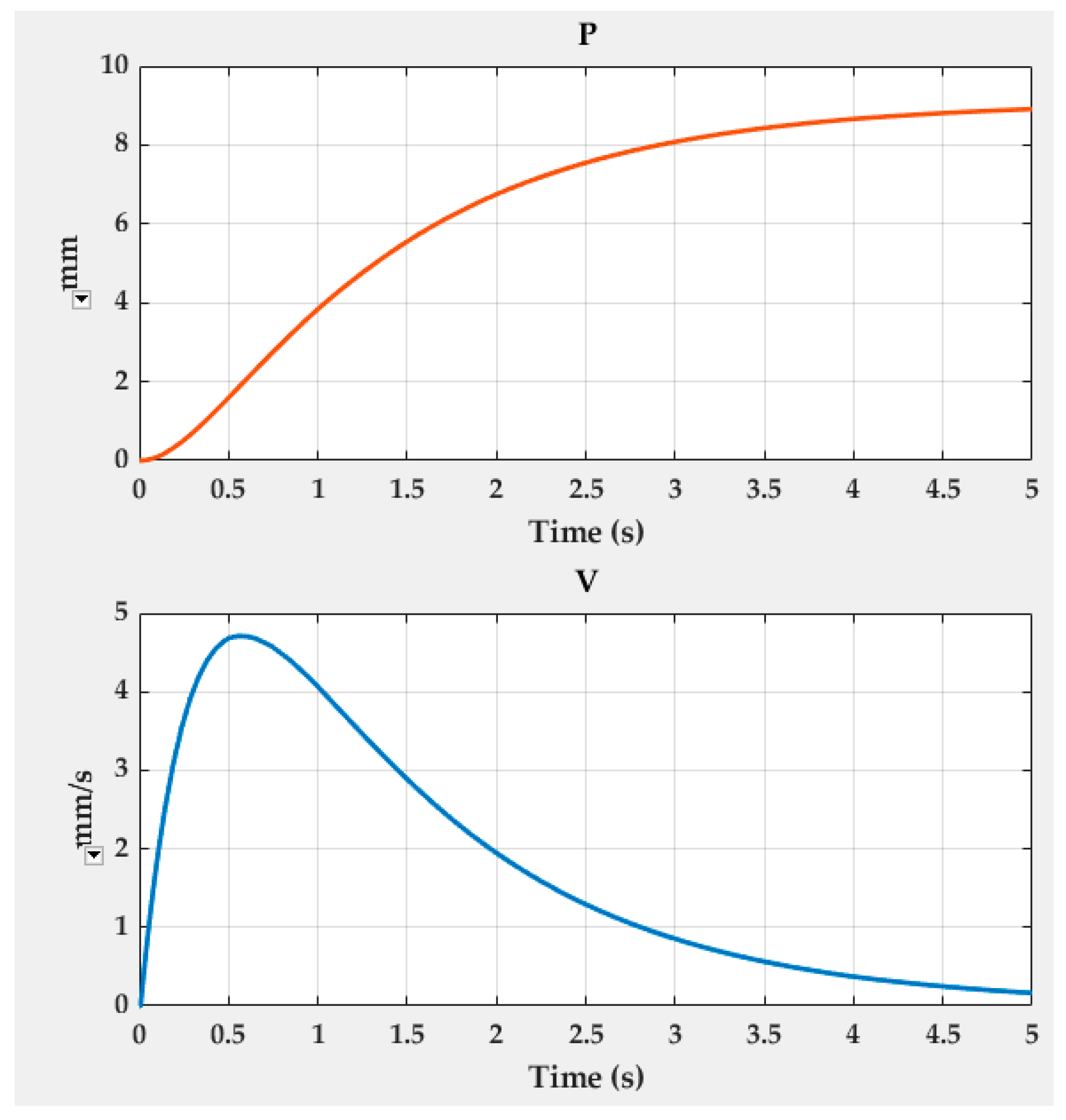
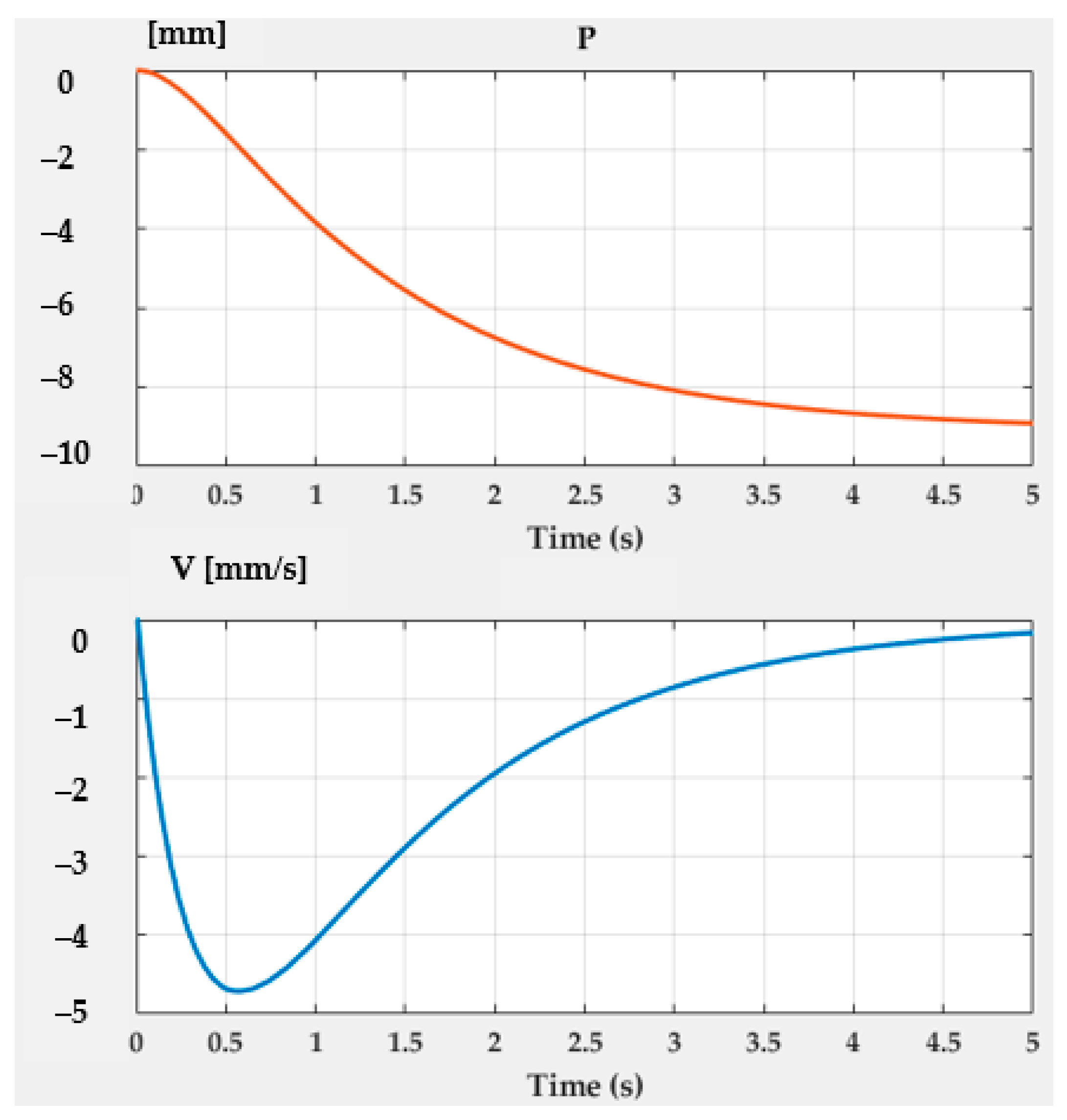
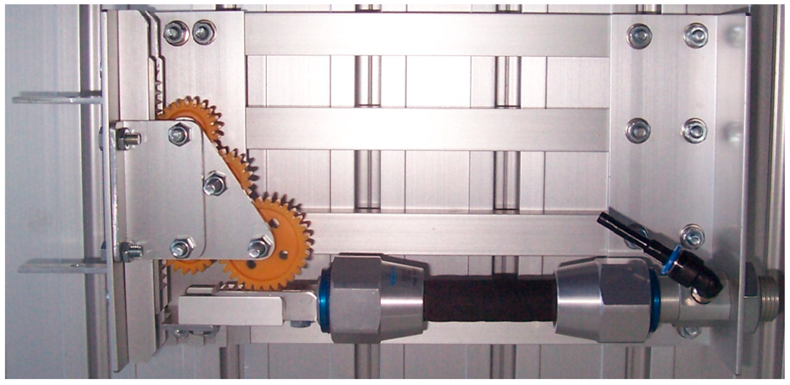
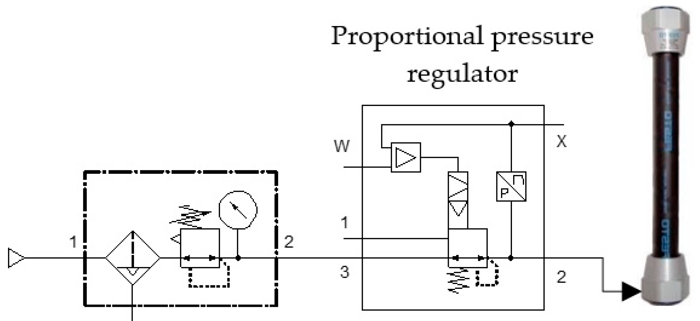
Section 3 introduces the kinematic diagram. Further, the gripper’s dynamic behavior is analyzed and validated by the model-based design technique available in MatLab. The section concludes with the constructive model of the novel soft gripper system and its pneumatic actuation diagram. The Section 4 analyzes the experimental results. The calculation method of compliance and stiffness is presented as well as their characteristic curves for two charging pressures of the muscle. Recommendations for the operation of the gripper system are also formulated. The Section 5 is dedicated to the main conclusions of the study.

2. Adjustable Compliance—An Essential Property in Automated Assembling Operations

In manual assembling the human operator is capable of noticing and overcoming difficulties caused by the lateral and angular misalignment of the paired parts. This is due to the operator’s intelligence, experince, and the tactile abilities of the fingers (their adaptive behavior). In addition, closed-loop control is ensured by the connection between the human senses and the brain [20].
In automated robotized assembling operations, the occurrence of component misalignment (peg in a hole) is quite likely. In the case of a slightly deviated alignment, the contact of the two parts will no longer be perfect as the peg touches first a side of the hole, its tip being subjected to the action of a lateral force. As the entire gripper system is not perfectly rigid, the peg will tend to rotate around the so-called center of compliance. Such rotation will cause an even more unfavorable alignment of the peg, an increase in lateral force, and an additional rotation. The result will be a blockage that hinders the completion of the assembling process. This can be avoided by using sensors, feedback, and compensation—a solution that may entail significant costs related to design, operation, and maintenance [21].
The jamming of the assembly components can be prevented by using remote centre compliance mechanisms (RCC). Typically placed at the interface between the robot arm and the gripper system, RCC facilitates the gripping assembly’s motion in a plane perpendicular to the peg axis. The system’s compliance allows the peg to automatically realign its axis with that of the hole without relying on any force sensory feedback.
A soft gripper system with adjustable compliance can be obtained by using a variable stiffness linear actuator of pneumatic-muscle type. Pneumatic artificial muscles (PAM) are flexible actuators conceived to mimic the motions of human muscles. Their importance in robotics and medicine has been proved by research that highlighted their compliant behavior. The utilization of pneumatic muscles for gripping purposes allows for the building of light and flexible structures and the safe handling of objects.
Grabbing and fixing fragile objects between jaws calls for adaptable gripper systems. 
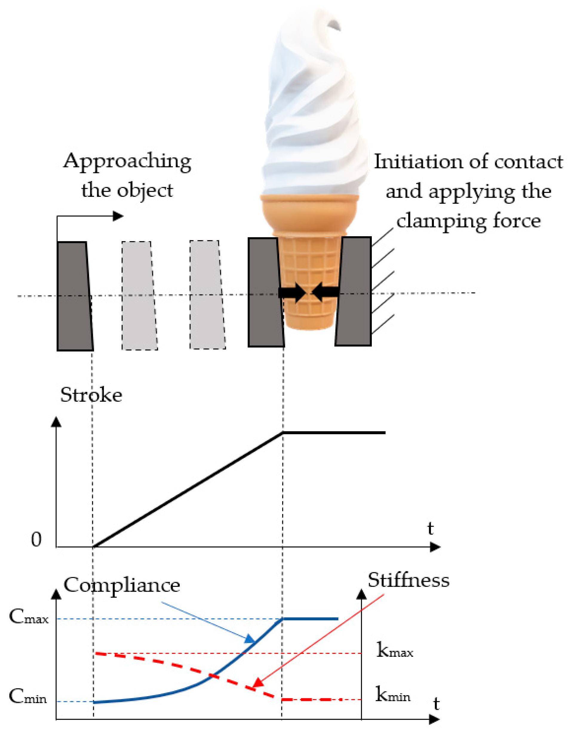
Figure 1 shows the desired variation of the compliance and stiffness of a gripper system with the displacement of the jaws.
The essential stages in the grabbing and fixing of the object are approaching the object, initiation of contact, and securing the object between the jaws by increasing the clamping force. Initially, during the approaching and positioning phase of the jaws in relation to the object to be gripped, the system’s stiffness has to be high and its compliance has to be minimal. Once the jaws have made contact with the object, its deformation has to be prevented, and consequently, the system’s compliance has to reach a maximum, while the stiffness has to decrease to minimum values. Of interest is also the shape of the two curves that illustrates the variation of compliance and stiffness, respectively. The compliance curve has to be concave, thus indicating compliance increase by a small gradient at the onset of jaw motion. At the end of the jaw stroke, compliance has to increase steeply in order to reach maximum values at the moment of contact with the gripped object. Maintaining compliance at a high value facilitates the assembling of the gripped object into the counterpart.
The requirements laid out above are met by a novel constructive solution of a gripper system presented further on. This system has the capacity to adapt its behavior continuously between two extremes, from flexibility to stiffness and vice versa.

3. Construction of the Gripper System

3.1. The Kinematic Diagram of the Gripper System

The proposed constructive variant includes two jaws, each with one degree of mobility. Power is transmitted to the two jaws by means of gears and racks. The pneumatic muscle is positioned asymmetrically in order to allow the proportional pressure regulator that controls the motion of the motor to be fitted into the metal housing of the system. A further reason for the asymmetrical position of the pneumatic muscle is to create the space needed to introduce the gears organized in two parallel linkages. By the connection of the mechanisms, the analyzed gripper system is an aggregate of the mixed type, where the two serial mechanisms are parallel connected starting with the power node at gear 2. Figure 2 shows the positioning of the utilized components.
The input values of the system are the speed (v1) and the force (F1) developed by the pneumatic muscle. Speed and force are transmitted to the jaws by means of two parallel linkages. The two outputs of the system represent its external links to the gripper jaws; thus, each jaw has its specific speed (v4 and v7, respectively) and force (F4 and F7, respectively) that act in opposing directions.
The designed gripper system incorporates the following gears and racks: racks 1, 4 and 7: 1 mm module; z2: 30 teeth; and z3, z5, and z6 each 20 teeth. The assembly described above was dimensioned based on the following input data: mass of the gripped object m = 0.7 kg; acceleration of the system consisting of the gripper and the gripped object: a = 5 m/s2; gravitational acceleration: g = 9.81 m/s2; deceleration at emergency stopping: as = 10 m/s2; friction coefficient: µ = 0.2; safety coefficient: S = 2.5. For these values, the necessary force to be developed by each jaw for retaining the gripped object is calculated by Equation (1):
F G = m · ( g + a S ) · S μ · n = 0.7 · ( 9.81 + 10 ) · 2.5 0.2 · 2 = 86.67 N
The proposed gripper system consists of two jaws (n = 2), and consequently the selected pneumatic muscle must be able to generate a force of at least 2 × 86.67 N, that is 173.34 N. Starting from the requirements related to operation and general dimensions, a MAS-10-45N-AA-MC-O-ER-EG pneumatic muscle manufactured by Festo, Germany was selected, with an interior diameter of 10 mm and an active length of 45 mm. The maximum axial contraction of a muscle is about 20% of its initial length, thus in this case, ΔLmax = 9 mm. The characteristic curves of the forces developed by this muscle versus pressure and axial contraction (stroke) are shown in Figure 3:
In order to ensure the force necessary for gripping an object of m = 0.7 kg, that is in order for each jaw to develop a force of 86.67 N, the range of the muscle’s axial contraction results from the diagram above (marked green). Thus, at a pressure of 6 bar of the compressed air, the maximum contraction of the pneumatic muscle is about 4.5 mm, causing the two jaws to draw closer by 9 mm. At a pressure of 4 bar, the maximum displacement of one jaw is 2 mm.

3.2. Functional Model of the Gripper System

The operational behavior of the gripper system—currently under development—was studied by a technique known as model-based design (MBD). MBD helps identify design errors, thus saving time and improving the quality of the analyzed system. For the analysis and validation of dynamic systems, model-based design uses mathematical models/algorithms and their graphic/visual representations. The functional model of the gripper system (Figure 4) was conceived with the graphical extension Simulink® of Matlab® R2021b. Simulink® includes Simscape™, a graphical programming environment for the modelling, simulation. and analysis of dynamic systems. For the modelling of fluidic systems, Simscape™ Fluids™ is used, providing a set of components specific to this field. The model of the gripper system includes both the kinematic structure of the mechanical assembly and the dimensional parameters of its components.
Modelling and simulation of the gripper’s motions starts from conducting an object gripping exercise consisting of the displacement (approaching) of the jaw-bearing racks over an interval of 5 s.
The functional model (Figure 4) was built with blocks from the Simulink Library. A pneumatic-muscle-type block (Air Muscle Actuator) was used, with characteristics based on the Chou and Hannaford model [22]. The pneumatic muscle is charged with compressed air via a Proportional Valve Actuator. This block represents an electromagnetic actuator that is used in proportional and servo-valves to drive a spool. It is conceived to function together with a 3-Way Directional Valve in order to create the desired configuration of a proportional valve.
Upon the generation of a ramp-type signal of the shape shown in Figure 5, the 3-Way Directional Valve opening fraction is set by the physical signal port S. A positive physical signal opens the connection between ports P and A and closes the connection between ports A and T.
The slow charging of the pneumatic muscle with compressed air causes its axial contraction, its variation versus time is visualized by means of block Scope2 (Figure 6).
The displacement of rack 1 by 9 mm causes the rotation of pinion 2. The variation of its rotation angle versus time is shown in Figure 7:
The rack and pinion mechanism connected to the free end of the pneumatic muscle further ramifies towards the two effector elements (jaws) of the gripper system (Figure 2). One branch consists of the Simple Gear block (Figure 4) formed by gears 2 and 3 and the Rack and Pinion 1 block consists of pinion 3 and rack 4. The other branch includes the Gear Box block, consisting of gears 2 and 5, and 5 and 6, respectively, and the Rack and Pinion 2 block, consisting of pinion 6 and rack 7.
The motions of the two racks (4 and 7)—displacements and speeds—are monitored by blocks Scopes 3 and 4 (Figure 8 and Figure 9).
In the figures above it can be observed that the displacements of the two jaw-bearing racks effectively reach the maximum 9 mm threshold provided by the pneumatic muscle. Further noticeable in this functional sequence is an initial rapid increase in speed up to approximately 4.8 mm/s. Subsequently, the motion progresses smoothly and without shocks until it comes to a complete stop, indicating a secure grip on the targeted object.

3.3. Constructive Model of the Gripper System

The construction of the gripper system is presented in Figure 10, and its actuation diagram in Figure 11.
The pneumatic diagram includes an MPPES-3-1/4-6-010 proportional pressure regulator (Festo, Germany) that receives an electric signal from an external potentiometer. This system allows the continuous adjustment of the regulator’s feeding voltage, causing constant variations of the air pressure in the pneumatic muscle. This is a pressure-based control scheme where the pressure in the pneumatic muscle is measured and controlled in a closed-loop system. Due to the strong hysteresis in the muscle’s behavior, it became necessary to determine the functions that describe the variation of the force generated at the jaw versus pressure, at the charging and discharging of the muscle, respectively. These functions underlie the control of the proportional pressure regulator. A specially developed computer program based on these polynomial equations is loaded into a PLC. The PLC sends an electric signal to the proportional pressure regulator whose voltage is continuously modified according to the polynomial functions [23]. The possibility of continuously modifying the air pressure influences the compliance of the whole system.

4. Experimental Results

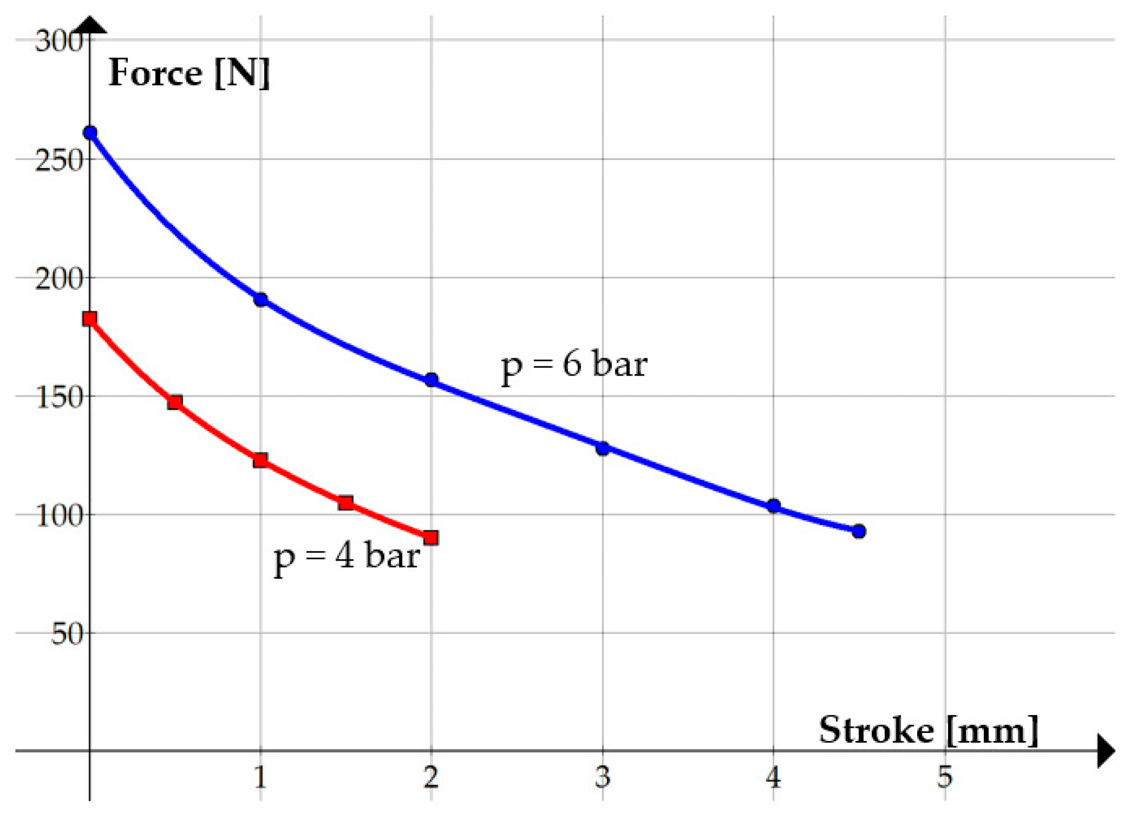
Experimental research was aimed at determining the force developed at the jaw level and the stiffness/compliance of the gripper system. The maximum force that can be developed by a jaw was measured with the attached force sensor. 
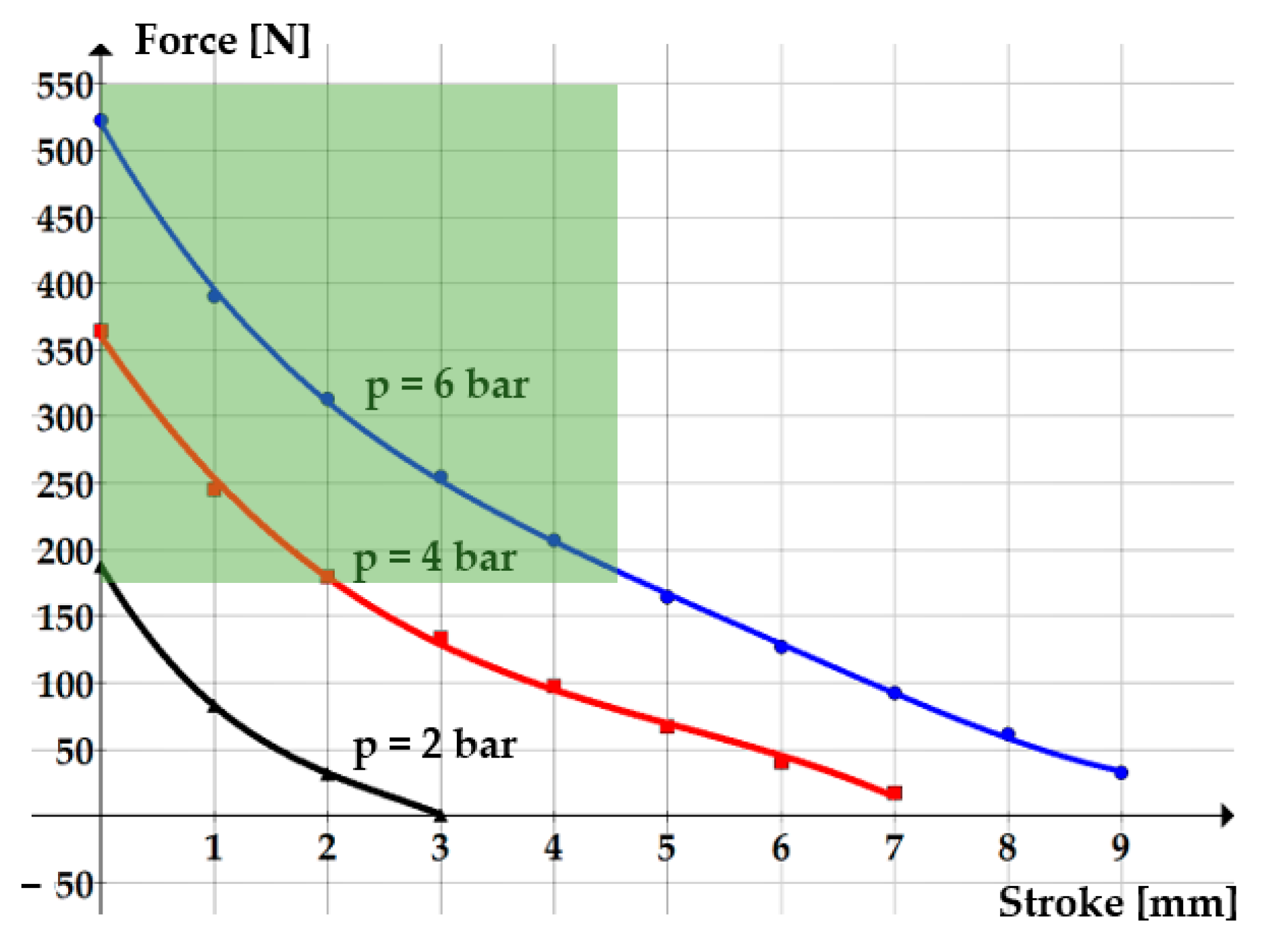
Table 1 presents the values of the measured forces for different strokes carried out by a jaw at charging pressures of 6 bar and 4 bar, respectively. Figure 12 shows the graph plotted with these data.
The maximum limits of jaw displacement were set at 4.5 mm and 2 mm, respectively, enabling the developed force to sustain an object of 0.7 kg.
Equations (2) and (3) are the regression functions of the curves shown in Figure 12:
F 6   b a r s = 0.8 · s 4 9.227 · s 3 + 39.48 · s 2 101.1 · s + 260.91
F 4   b a r s = 1.53 · s 4 11.13 · s 3 + 36.01 · s 2 85.81 · s + 182.1
It is known that for a system to be compliant, the dependency of the developed force (F) on its stroke (s) has to be nonlinear. 
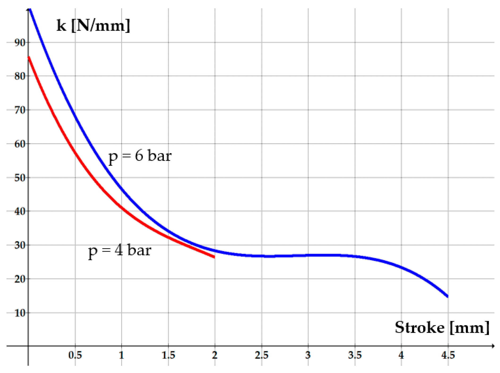
Figure 12 shows a nonlinear decrease in the force as the jaw stroke increases. Consequently, variable stiffness k and compliance C are obtained, described by the following equations:
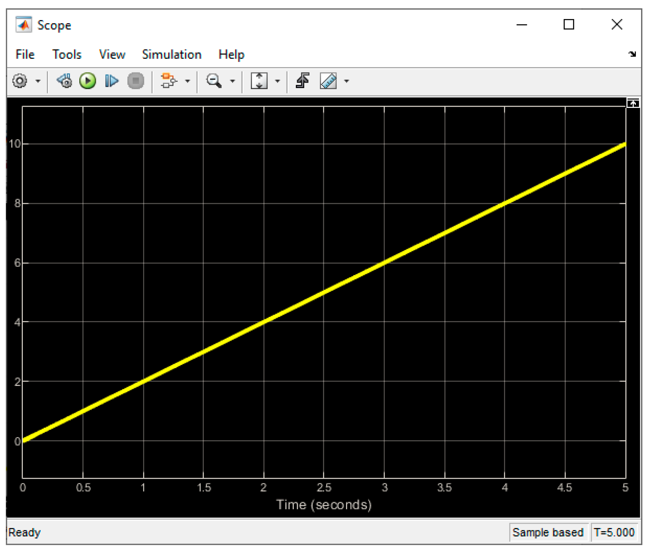
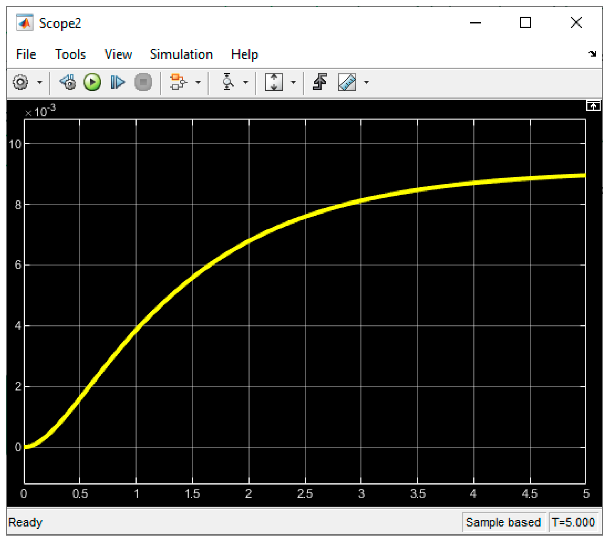
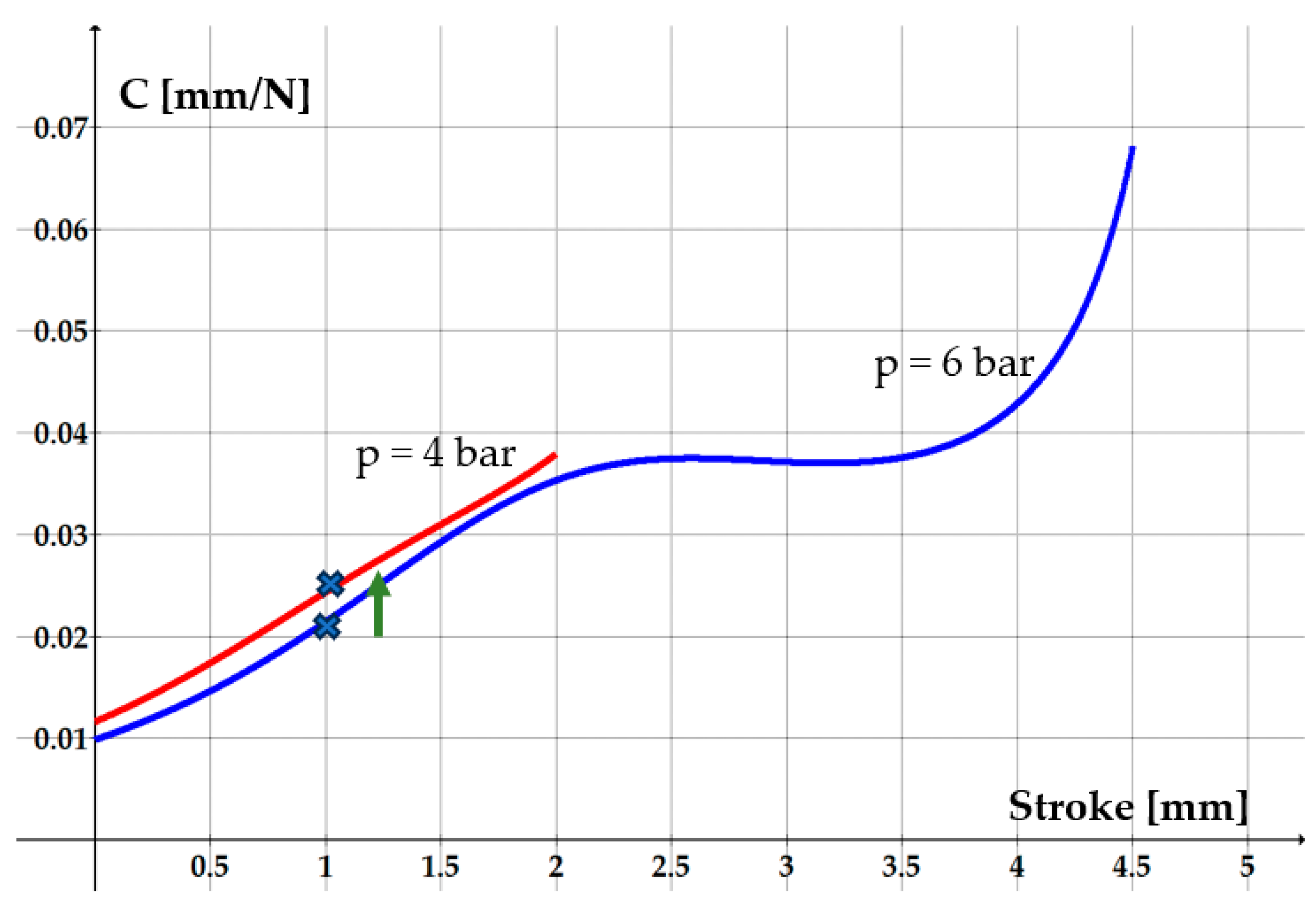
k 6   b a r ( s ) = d F 6   b a r d s = ( 3.2 · s 3 27.68 · s 2 + 78.96 · s 101.1 )
k 4   b a r ( s ) = d F 4   b a r d s = ( 6.12 · s 3 33.39 · s 2 + 72.02 · s 85.81 )
C 6   b a r = k 6   b a r 1 = 1 ( 3.2 · s 3 27.68 · s 2 + 78.96 · s 101.1 )
C 4   b a r = k 4   b a r 1 = 1 ( 6.12 · s 3 33.39 · s 2 + 72.02 · s 85.81 )
Figure 13 and Figure 14 show the variations of stiffness and compliance, respectively, versus the stroke of one jaw.
The two graphs confirm the hypotheses presented in Figure 1, indicating that the stiffness tends to decrease and compliance increases while the jaws draw closer to the object to be gripped. As the moment of contact and firm securing of the object approaches, the shape of the compliance curve becomes concave, its gradient increases and the system’s compliance rapidly reaches high values.
Figure 14 illustrates that once contact has been made with the object, an adequate adjustment of the working pressure can determine certain values of compliance. The example presented in the figure demonstrates that for a jaw stroke set at 1 mm, reducing air pressure from 6 bar to 4 bar leads to an increase of compliance from 0.0215 to 0.0244 mm/N. The higher the compliance is, the more adequate the system becomes for the handling of fragile or easily deformable objects. Also, high compliance facilitates the assembling of the gripped object with a counterpart by compensating for misalignments.
The gripper system presented in this paper is in the test phase. One of the observed disadvantages is the hysteresis phenomenon induced by friction. When used for assembling operations, however, hysteresis is not an impediment, as it occurs in the initial phase, when the object is grasped prior to assembling, and in the final phase, when the assembled object is released. A further disadvantage is the presence of a threshold pressure that delays the development of force by the pneumatic muscle. This inconvenience is, however, of lesser importance in assembling operations. Follow-up research is to be conducted, aimed at addressing the effects of hysteresis and of the threshold pressure.

5. Conclusions

The paper proposes a soft gripper system notable for its simple structure that can be manufactured at a low cost and has a morphology easily adaptable to various applications. Actuation is ensured by a pneumatic muscle that is an inherently compliant actuator. This property is extremely beneficial, as it allows in automated assembling operations the compensation of lateral or angular misalignments.
The diagram of principle, the functional model and the construction of the gripper system were presented. The forces that can be developed by this novel system were studied, as well as its behavior related to stiffness and compliance. Compliance can be adjusted by varying the air pressure in the pneumatic muscle, which is monitored and controlled in a closed loop by means of a proportional pressure regulator. The behavior of the gripper system meets the requirements for a device of this type, that is to allow soft gripping of an object and flawless blockage-free assembling.
In addition to other soft gripper systems available on the marketplace developed for assembling operations, the model presented in this paper can also be used for other applications, like the manipulation of fragile, easily deformable objects. The possibility of adjusting compliance allows the limitation of the contact forces to values that are acceptable in safe handling, without making feedback necessary. While the soft gripper system presented in the paper is lightweight and compact, it is susceptible to improvements related to the actuator itself, to the modality of compliance control, as well as to widening the range of its applicability.

Author Contributions

Conceptualization, T.D.; methodology, A.D.; validation, A.D. and T.D.; investigation, A.D. and T.D.; writing—original draft preparation, A.D.; writing—review and editing, A.D. and T.D.; supervision, T.D. All authors have read and agreed to the published version of the manuscript.

Funding

This research received no external funding.

Institutional Review Board Statement

Not applicable.

Informed Consent Statement

Not applicable.

Data Availability Statement

Data are contained within the article.

Conflicts of Interest

The authors declare no conflicts of interest.

References

  1. Bar-Cohen, Y. Biomimetics—Using nature to inspire human innovation. J. Bioinspiration Biomim. 2006, 1, P1. [Google Scholar] [CrossRef]
  2. Dieter, G.E. Engineering Design: A Material and Processing Approach, 3rd ed.; McGraw-Hill: Boston, MA, USA, 2000. [Google Scholar]
  3. Ulrich, K.T.; Eppinger, S.D.; Yang, M.C. Product Design and Development, 7th ed.; McGraw–Hill/Irwin: Boston, MA, USA, 2004. [Google Scholar]
  4. Rus, D.; Tolley, M.T. Design, fabrication and control of soft robots. Nature 2015, 521, 467–475. [Google Scholar] [CrossRef] [PubMed]
  5. Elsamanty, M.; Hassaan, M.A.; Orban, M.; Guo, K.; Yang, H.; Abdrabbo, S.; Selmy, M. Soft Pneumatic Muscles: Revolutionizing Human Assistive Devices with Geometric Design and Intelligent Control. Micromachines 2023, 14, 1431. [Google Scholar] [CrossRef]
  6. Shintake, J.; Cacucciolo, V.; Floreano, D.; Shea, H. Soft Robotic Grippers. Adv. Mater. 2018, 30, 1707035. [Google Scholar] [CrossRef] [PubMed]
  7. Wolf, S.; Grioli, G.; Eiberger, O.; Friedl, W.; Grebenstein, M.; Höppner, H.; Burdet, E.; Tsagarakis, N.G.; Visser, L.C.; Catalano, M.; et al. Variable Stiffness Actuators: Review on Design and Components. IEEE/ASME Trans. Mechatron. 2015, 11, 2418–2430. [Google Scholar] [CrossRef]
  8. Weipeng, Z.; Peng, Y. A variable stiffness compliant actuator based on antagonistic normal-stressed electromagnetic mechanism. Sens. Actuators A Phys. 2024, 366, 114983. [Google Scholar]
  9. Remote Center Compliance. Available online: https://en.wikipedia.org/wiki/Remote_center_compliance#:~:text=In%20robotics%2C%20a%20remote%20center,a%20hole%20with%20tight%20clearance (accessed on 28 December 2024).
  10. Deaconescu, A.; Deaconescu, T. Tribological Behavior of Hydraulic Cylinder Coaxial Sealing Systems Made from PTFE and PTFE Compounds. Polymers 2020, 12, 155. [Google Scholar] [CrossRef] [PubMed]
  11. Navas, E.; Shamshiri, R.R.; Dworak, V.; Weltzien, C.; Fernández, R. Soft Gripper for Small Fruits Harvesting and Pick and Place Operations. Front. Robot. AI 2023, 10, 1330496. [Google Scholar] [CrossRef] [PubMed]
  12. Tiboni, M.; Loda, D. Monolithic PneuNets Soft Actuators for Robotic Rehabilitation: Methodologies for Design, Production and Characterization. Actuators 2023, 12, 299. [Google Scholar] [CrossRef]
  13. Wang, W.; Tang, Y.; Li, C. Controlling bending deformation of a shape memory alloy-based soft planar gripper to grip deformable objects. Int. J. Mech. Sci. 2021, 193, 106181. [Google Scholar] [CrossRef]
  14. Cacucciolo, V.; Shintake, J.; Shea, H. Delicate yet Strong: Characterizing the Electro-Adhesion Lifting Force with a Soft Gripper. In Proceedings of the RoboSoft 2019—2019 IEEE International Conference on Soft Robotics, Seoul, Republic of Korea, 14–18 April 2019; pp. 108–113. [Google Scholar]
  15. Li, H.; Xie, D.; Xie, Y. A Soft Pneumatic Gripper with Endoskeletons Resisting Out-of-Plane Bending. Actuators 2022, 11, 246. [Google Scholar] [CrossRef]
  16. Lei, J.; Ge, Z.; Fan, P.; Zou, W.; Jiang, T.; Dong, L. Design and Manufacture of a Flexible Pneumatic Soft Gripper. Appl. Sci. 2022, 12, 6306. [Google Scholar] [CrossRef]
  17. PowerGripper. Available online: https://www.festo.com/gb/en/e/about-festo/research-and-development/bionic-learning-network/highlights-from-2010-to-2012/powergripper-id_33664/ (accessed on 27 December 2024).
  18. Hamon, P.; Michel, L.; Plestan, F.; Chablat, D. Model-free based control of a gripper actuated by pneumatic muscles. Mechatronics 2023, 95, 103053. [Google Scholar] [CrossRef]
  19. Arachchige, D.D.K.; Chen, Y.; Walker, I.D.; Godage, I.S. A Novel Variable Stiffness Soft Robotic Gripper. In Proceedings of the IEEE International Conference on Automation Science and Engineering (CASE), Lyon, France, 23–27 August 2021. [Google Scholar]
  20. Monkman, G.J.; Hesse, S.; Steinmann, R.; Schunk, H. Robot Grippers; Wiley-VCH Verlag GmbH&Co.: Weinheim, Germany, 2007. [Google Scholar]
  21. Ciblak, N.; Lipkin, H. Design and Analysis of Remote Center of Compliance Structures. J. Robot. Syst. 2003, 20, 415–427. [Google Scholar] [CrossRef]
  22. Chou, C.P.; Hannaford, B. Measurement and modeling of McKibben Pneumatic Artificial Muscles. IEEE Trans. Robot. Autom. 1996, 12, 90–102. [Google Scholar] [CrossRef]
  23. Petre, I.; Deaconescu, A.; Sârbu, F.; Deaconescu, T. Pneumatic Muscle Actuated Wrist Rehabilitation Equipment Based on the Fin Ray Principle. Stroj. Vestn.—J. Mech. Eng. 2018, 64/6, 383–392. [Google Scholar]
Figure 1. Variation versus time of jaw stroke and system compliance/stiffness.
Technologies 13 00086 g001
Figure 2. Kinematic diagram of the gripper system.
Technologies 13 00086 g002
Figure 3. Variation of the force versus the stroke and charging pressure.
Technologies 13 00086 g003
Figure 4. Functional model of the soft gripper system.
Technologies 13 00086 g004
Figure 5. Ramp-type input signal.
Technologies 13 00086 g005
Figure 6. Variation of the pneumatic muscle’s contraction versus time.
Technologies 13 00086 g006
Figure 7. Variation versus time of the rotation angle of gear 2.
Technologies 13 00086 g007
Figure 8. Variation versus time of the speed and velocity of rack 4.
Technologies 13 00086 g008
Figure 9. Variation versus time of the speed and velocity of rack 7.
Technologies 13 00086 g009
Figure 10. Construction of the soft gripper system.
Technologies 13 00086 g010
Figure 11. Control of the gripper system by means of a proportional pressure regulator.
Technologies 13 00086 g011
Figure 12. Variation of the forces developed by a jaw versus its stroke.
Technologies 13 00086 g012
Figure 13. Variation of stiffness versus jaw stroke at a pressure of 4 and 6 bar.
Technologies 13 00086 g013
Figure 14. Variation of compliance versus jaw stroke at a pressure of 4 and 6 bar.
Technologies 13 00086 g014
Table 1. Force and stroke values.
p = 6 bar
Stroke [mm]012344.5
Force [N]261.1190.4156.6127.6103.592.7
p = 4 bar
Stroke [mm]00.511.52
Force [N]182.1146.9122.7104.690
Disclaimer/Publisher’s Note: The statements, opinions and data contained in all publications are solely those of the individual author(s) and contributor(s) and not of MDPI and/or the editor(s). MDPI and/or the editor(s) disclaim responsibility for any injury to people or property resulting from any ideas, methods, instructions or products referred to in the content.

