Abstract
TiNi-based alloys are widely utilized in various engineering and medical applications. This study presents a newly developed and optimized technology for producing TiNi wires with a diameter of 40 μm utilizing a combined mechano-chemical treatment and drawing process. The resulting thin wires were tested and characterized using multiple methods to determine their structural, phase, and mechanical properties. The structure of the TiNi wires, designed for use as textile implants in reconstructive medicine, features a TiNi metal matrix (B2 and B19′ phases) at the core and a surface oxide layer. A key structural characteristic of these wires is the presence of fine nanograins averaging 15–17 nm in size. No texturizing of the metallic material was observed during repeated plastic deformations throughout the drawing process. The applied mechano-chemical treatment aimed to modify the structure of the wires’ surface oxide layer. Specifically, reducing the thickness and roughness of this layer decreased the friction coefficient of the alloy during drawing, thus significantly reducing the number of breaks during production. At the same time, the cryogenic treatment of the final product was found to stabilize the martensitic phase B19′, which reduces the Young’s modulus by 10 GPa. Consequently, this newly developed methodology enhances the material’s quality and reduces labor costs during production.
1. Introduction
Nickel titanium (TiNi), also known as nitinol, is a series of metal alloys composed of nickel and titanium in roughly equal atomic percentages [1,2,3,4,5,6,7]. TiNi-based alloys are renowned for their shape memory effect and superelasticity, coupled with excellent corrosion resistance, mechanical properties, and biocompatibility [1,2,3,4,5,8,9,10,11]. The shape memory effect and superelasticity of these alloys are related to thermoelastic martensitic transformations (MTs), which involve a phase change from austenite to martensite. These transformations can be triggered either by cooling or by applying stress. Martensite formation begins when the material is cooled below its martensite start temperature (Ms) and completes at the martensite finish temperature (Mf). The transformation is reversible, which is why the austenite start temperature (As) and austenite finish temperature (Af) are defined as the temperatures when the reverse transformation from martensite to austenite begins and ends upon heating, respectively [1,7,12].
At the same time, these materials exhibit a unique combination of physico-chemical properties, including high chemical stability, making them highly attractive for numerous biomedical applications. They are highly biocompatible and possess properties suitable for use in stents, medical instruments, and bone reconstruction materials, as well as in orthopedic, orthodontic, and ophthalmologic implants [10,11,12].
TiNi-based materials can be produced using various approaches, resulting in different structural forms and shapes. The most common forms include monolithic, porous, and composite materials (see Figure 1) [4,5,10,11,13,14]. As seen in Figure 1, the wide variety of TiNi materials with different structures and surface morphologies can be considered for diverse applications in medicine as various functional materials [9,10,15]. Monolithic materials are typically processed through rolling, forging, and drawing, resulting in plates, bars, and wires [16,17,18,19]. Drawing wires to diameters of 30–60 μm produces thin threads, which are then used as suture materials and for weaving textile and felting materials [17,18,19]. Porous TiNi materials are used to create porous structures, while varying the degrees of milling produces powders and granular materials [11,20,21,22,23]. Finally, the combined use of monolithic and porous TiNi materials results in composite porous–monolithic materials, which integrate the properties of both monolithic and porous TiNi [24].
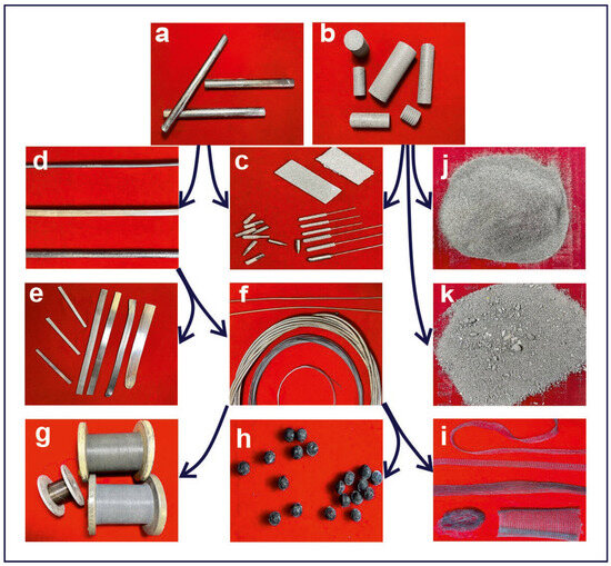
Figure 1.
Main forms of TiNi produced industrially for biomedical applications or as components for further implant manufacturing: (a) monolithic materials; (b) porous materials; (c) composite porous–monolithic implants; (d) rods; (e) plates or sheets; (f) wires; (g) sutures; (h) felted materials; (i) textiles; (j) powders; and (k) granules. Arrows indicate relationships between materials and their original monolithic or porous TiNi forms.
As mentioned above, the combination of high anticorrosive stability and unique mechanical and deformation properties makes TiNi alloys highly attractive for numerous biomedical technologies [4,5,9,15,25,26]. TiNi-based alloys have been successfully used in various biomedical applications, including stents [6,13,27,28,29], clips for osteosynthesis and bone regeneration [5,9,15,30,31], dental implants [10,32,33,34] and brackets [10,35], sewing textile materials [19,36], porous and composite implants [4,11,21,22,23,24,37,38], as well as medical instruments and their components [39].
Among various implants, those based on TiNi textiles are particularly effective for the correction and restoration of soft tissues and organs, setting them apart from other materials [17,36]. The advantages of such textile implants, which utilize thin TiNi threads, include low specific weight, high permeability, significant reversible deformation, and ultimate strength. These benefits arise from the properties of the thin TiNi threads and the method used to create the textile structure. Consequently, TiNi nets are highly successful in plastic and regenerative surgery of soft tissues, where they support relatively large areas of recovered skin or other soft tissues [17,18,36].
The structural elements of these textile implants are thin TiNi wires, typically with a diameter of less than 100 μm, which are usually obtained through the drawing method [17,18]. For example, Tsuchiya et al. produced TiNi-based wires by cold drawing, achieving an area reduction of 50–70% using diamond dies at a drawing speed of 50 m/min without intermediate annealing [18]. As a result, the amorphous phase dominated in the as-prepared material, coexisting with the nanocrystalline austenitic phase TiNi (B2), while the martensitic phases (B19′ and R) were absent. Amorphous–crystalline TiNi wires are known to exhibit high tensile strength (2 GPa), a high elastic modulus (71 GPa), and superelasticity (>5%) after aging. Therefore, this material has been concluded to have significant potential as a new material for medical devices such as vessel stents [18]. However, the use of such alloys is somewhat limited due to their high Young’s modulus and relatively large diameter, which complicates the creation of textile implants.
The preparation of thin TiNi wires using powder metallurgy and the combustion synthesis process, which relies on the exothermic reaction between Ti and Ni, has also been demonstrated [20]. The resulting billets underwent mechanical pressure treatment (hot forging, hot rolling, and cold drawing), producing flat wires with a width of 2.18 mm and a thickness of 0.92 mm [20]. The authors reported the dependence of the TiNi transformation temperature on the Ni content after heat treatment by aging at 783 K for 25 min following 20% cold rolling. The martensitic transformation (MT) temperature of the wires decreased rapidly with increasing Ni content, consistent with existing theories. However, at a Ni concentration of 51.7 at.%, an increase in characteristic MT temperatures was observed due to the formation of Ti3Ni4 particles [20]. It should be noted that Ni-enriched TiNi-based alloys are known for their high superelasticity and high modulus of elasticity.
In contrast to the above-mentioned approaches, Saito and coworkers obtained thin TiNi wires with equiatomic composition and diameters less than 100 μm [17]. They described a process for fabricating nitinol wires as thin as 30 μm in diameter using clad-chip extrusion (CCE) combined with drawing. In this method, thin Ti-Ni-Ti sandwich chips were used as feedstock. The CCE-fabricated wires exhibited higher values for Young’s modulus, yield strength, and other functional properties compared to those produced by the casting method. However, this approach requires very thin layers of Ti and Ni in the Ti-Ni-Ti composite to suppress the formation of Kirkendall voids, as the diffusion coefficient of Ni in β-Ti is 40,000 times higher than that of Ti in Ni. Additionally, the method is labor-intensive and results in wires that are not suitable for textile structures [17].
To produce thin TiNi wires for various implants, Gunther and coworkers proposed a technique based on direct exposure to infrared (IR) irradiation [19]. IR irradiation was shown to have a minimal impact on the core of the matrix of the as-produced TiNi wires while significantly affecting the structure of the near-surface layer by making it more homogeneous and free from inclusions. The concentration of Ti and Ni atoms in the wire’s core remained practically unchanged. However, TiNi wires obtained with the help of IR irradiation demonstrated significantly higher oxygen concentrations in their surface layer upon reducing their diameter, which had a positive effect on the biocompatibility of the material [19]. This was achieved due to a thicker surface oxide layer, which can reduce the physico-mechanical properties of the material, as massive oxide films are prone to cracking and delamination. Consequently, this makes it difficult to produce fine TiNi yarns and damages needles during loom operation due to the abrasive properties of the oxide layer on such fine threads. Brileanu et al. demonstrated that, depending on the state of the surface TiO2 oxide and its share in the lubricant, it can either act as a lubricating additive or as an abrasive [40]. They also found that the diameter of the wear scar and the coefficient of friction increased with the volume concentration of TiO2 nanoparticles in the lubricating oil used [40].
Thus, the TiNi-based wires reported so far have a common problem: a high modulus of elasticity and a massive oxide layer on their surface, which is expected to result in a mismatch of their biomechanical behavior with the soft tissues of the human body. The elastic modulus of the martensitic phase TiNi (B19′) is known to be smaller compared to that of TiNi (B2) [1]. Stabilizing the martensitic phase in TiNi-based alloys is expected to help reduce the elastic modulus of the material. Additionally, the chemical surface treatment of TiNi-based wire, as adopted in the present work, was expected to significantly reduce the labor input and produce a material with a nanostructured state. This provided additional motivation for our study, with the expectation of achieving results with high applied value.
In light of the above, the aim of this work was to develop a new, cost-efficient technology for producing TiNi wires with improved mechanical properties, such as Young’s modulus. To achieve this, we investigated the effect of chemical treatment on the structural features and properties of thin TiNi-based wires obtained by drawing, followed by intermediate annealing and chemical surface treatment. We then studied the mechanical properties of the prepared TiNi wires, including their elastic modulus, and how these properties were related to martensite stabilization in the nanograined structure of the wires. The novelty and originality of this study lie in producing thin TiNi wires, with diameters as small as 40 μm, using a simple and low-cost technology. This approach enhances the producibility of fabricated TiNi threads with a nanograined structure and a Young’s modulus that is attractive for medical applications.
2. Materials and Methods
2.1. Material Preparation Technology
The subjects of the present work were thin TiNi wires with diameters down to 40 μm which were fabricated by drawing combined with intermediate stages of thermal and chemical treatment, as schematically illustrated in Figure 2. Initially, Ti-50 at.% Ni ingots were prepared via vacuum induction melting (VIM) using spongy titanium (TG-90, purity of 99.94%) and nickel (N1, purity of 99.90%), both sourced from Ural Metals, Kamensk-Uralsky, Russia. Both the titanium and nickel precursors, each chopped into ~30–35 mm fragments, were weighed and dosed into the VIM chamber using a GH-200 balance (A&D, Tokyo, Japan).
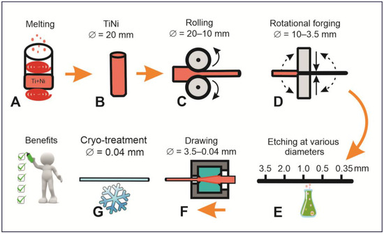
Figure 2.
Schematic presentation of technological steps used to prepare nanostructured TiNi wires with diameter ~40 μm. The following stages were involved: inductive melting of Ti and Ni (A), preparing the ingot for thinning (B), ingot rolling (C), rotational forging (D) followed by etching (at diameters of 3.5, 2.0, 1.0, 0.5, and 0.35 mm) (E) and drawing (F), and final cryo-treatment of wires with diameters of 0.04 mm (G).
To ensure a more efficient chemical reaction between Ti and Ni during their remelting, the two components were placed layer by layer in a carbon crucible inside an ISV-0.004-PI M1 induction vacuum furnace (Petra, Ufa, Russia). To avoid the interaction of the melt with carbon of the crucible, a protective layer of TiNi was created on its walls beforehand. Inductive heating was carried out at a pressure of 1 atm in Ar medium (99.99% pure, from Cryogenmash-Gas, Tomsk, Russia). The process of heating, melting, and chemical reaction between Ti and Ni in the liquid phase took about 10 min, after which the TiNi melt was poured into a vertical metal mold composed of heat-resistant steel where it was cooled for 1–1.5 h. The so-obtained ingot consisted of a main cylindrical part and upper cone-shaped part which contained the liquation zone, shrinkage sink, slag, and pores. The latter part was removed by a DOS 66 disk-cutting machine (KZDM, Armavir, Russia), after which the side surface of the cylindrical ingot was ground by a 3M636 grinding machine (KZDM, Armavir, Russia). As a result, a cylindrical ingot with a diameter of 20 mm and a length of 300 mm was obtained.
The initial thinning of the ingot, from 20.0 to 10.0 mm, was carried out by rolling with a DOU-80 rolling mill (DOU, Moscow, Russia, see Figure 2). The rolling process is known to be associated with accumulation of internal stresses caused by plastic deformation, which is why the sample was annealed in a SUOL 0.4.4/12 tube furnace (Tula-Term, Tula, Russia) at temperatures of 900–950 °C. After the rolling, the total compression (εΣ) was found to be 60%. Further thinning of the wire was achieved by means of a rotary forging machine (an RKM-4, Pressmash, Taganrog, Russia), resulting in a diameter of 3.5 mm (εΣ = 65%). Wires with diameters below 3.5 mm (down to 0.04 mm) were produced by drawing through several drawing machines due to different drawing forces and required tooling.
When the obtained TiNi wires reached a diameter of 2.5–3.5 mm, a catenary driving machine (CVM-1.5, from AZTM, Almaty, Kazakhstan) was used, while wires with diameters 2.5–0.4 mm and 0.4–0.04 mm used drawing machines SVP-0.12M and SVP-0.03M equipped with strain gauges for stress determination during drawing (both from Pressmash, Taganrog, Russia), respectively. After each drawing, the product was annealed at temperatures of 450–900 °C, with the latter temperatures being gradually decreased for thinner TiNi wires.
Finally, textile structures in the form of canvas were obtained using a Flat Bed Rishikesh Wire Knitting Machine (Rishikesh Electromatic Pvt. Ltd., Mumbai, India). The width of the produced fabric was 200 mm with a loop size of about 2 mm. During the knitting process, the wire was lubricated with machine oil to reduce friction within the weaving needles. After obtaining the fabric, it was first rinsed and washed with acetone and then further annealed in a furnace at about 450 °C for 10 min.
2.2. Material Modification Technology
Repeated high-temperature processing and plastic deformation are known to create an oxide scale on the wire surface, ranging from 0.07 to 22 µm thick [41]. When obtaining thin wire with diameters on the order of 40 μm, such a massive oxide scale can significantly increase the breakage frequency and lead to deterioration of the product’s quality. All this brought us to the necessity of chemical treatment of intermediate TiNi wires to improve their properties and facilitate subsequent drawing procedures. To decrease the Young’s modulus of the final product, the newly developed technology included cryo-treatment of fabricated TiNi wires. For this purpose, they were placed in a vessel with liquid nitrogen (99.99% pure, from Cryogenmash-Gas, Tomsk, Russia) for 1 min for the material to reach a temperature of −196 °C, which was confirmed visually by the completion of the boiling process.
In TiNi-based alloys, martensitic transformations are known to be realized in two ways: by changing temperature or stress. In the present work, the temperature method of obtaining martensitic transformation was used. The cryogenic cooling we used provided a complete transition to the martensitic phase of nanostructured material with a high content of grain boundaries and internal stresses. When the austenite–martensite interphase boundary moves and interacts with multiple grain boundaries, the reversibility of the transformation may be broken. As a result, the nanostructural state of the material leads to stabilization of the martensitic phase B19′ in the obtained thin TiNi wires.
To evaluate the effect of the novel processing stages on the surface and mechanical properties of the produced TiNi materials, two samples were extensively analyzed. Their fabrication conditions are detailed below and in Table 1. Sample A was produced using a conventional approach, specifically through multiple drawing cycles, which gradually reduced the product’s diameter from 20 mm to approximately 40 μm. Its counterpart, Sample B, prepared using the same procedures as Sample A, underwent additional treatment in diluted acidic solutions (HNO3, HF, and H2O in a 3:1:100 v/v ratio) for 24 h. To get rid of any residual acid, the obtained wire was rinsed under running water and then soaked in water for an additional 24 h. This treatment was applied to wires with diameters of 3.5, 2.0, 1.0, 0.5, and 0.35 mm, followed by surface polishing and cleaning on a grinding machine. The acids used were 65% nitric acid and 45% hydrofluoric acid, both chemically pure and purchased from SIGMATEK (Khimki, Russia).

Table 1.
Samples used for characterization.
2.3. Characterization
The structural features of the thin wires were investigated using X-ray diffraction (XRD) analysis, scanning electron microscopy (SEM), energy-dispersive X-ray spectroscopy (EDS), electron backscatter diffraction (EBSD), and transmission electron microscopy (TEM). For the SEM and TEM studies, the samples were prepared using a focused ion beam (FIB). The deformation properties of the experimental samples were studied by analyzing their stress–strain (σ(ε)) dependences.
2.3.1. Sample Preparation
Due to their small diameters, volumes, and masses, thin TiNi-based wires with diameters of 40 μm required special preparation for analysis. For XRD, Samples A and B were first cut into fragments using scissors, then stacked tightly together to form a rod with a diameter of 10 mm. The cross-section of this rod was then investigated. In the diffractometer, these samples were fixed on a special stage to maintain proper orientation.
For the SEM and TEM studies, lamellae were cut in both transverse and longitudinal directions of the TiNi wires. Such lamellae were obtained by a FIB using a Hitachi FB-2100 (Hitachi, Tokio, Japan) instrument, which is capable of etching material with Ga ions, depositing W to create a protective mask, and moving the lamellae with a manipulator. After cutting from the wires, the initial size of the lamella was 10 × 8 × 0.2 μm3. At this stage, SEM, EDS, and EBSD analyses were performed. Because the etching rate with Ga ions is high, difficult to control, and is accompanied by formation of an amorphous layer on the lamella surface, further (and final) thinning to 0.05 μm was carried out using Ar ion etching on a Leica EM RES102 (Leica Microsystems, Wetzlar, Germany) to meet the requirements for TEM.
2.3.2. X-Ray Diffraction Analysis (XRD)
The phase composition of the samples was investigated by means of an XRD 6000 diffractometer (Shimadzu, Kyoto, Japan) using CuKα-radiation with a wavelength of 1.54 Å at an accelerating voltage of 40 kV and a current of 30 mA. The diffraction angle range of 2Θ was 20–120° with sampling of 0.02° and a scanning speed of 1°/min. The phase composition analysis was performed using the PDF 4+ database and POWDER CELL 2.4 software with the pseudo-Voigt profile function. The lattice parameters were set using the Rietwild method, in which the diffraction profile is created based on a theoretical lattice model that describes the experimental diffractogram as accurately as possible.
2.3.3. Scanning Electron Microscopy (SEM)
The macro- and microstructure features of the experimental samples were studied in high vacuum conditions using Quanta 200 3D (FEI Company, Hillsboro, OR, USA) and TESCAN MIRA microscopes (TESCAN, Brno-Kohoutovice, Czech Republic) with the modes of secondary (SE) and back-scatter electrons (BSE). The accelerating voltage was 20–30 kV with a probe current of 0.5–1.3 nA. The chemical composition analysis and elemental mapping were performed by EDS using an EDAX Econ IV microanalyzer (EDAX, Mahwah, NJ, USA). The EBSD analysis was performed using an Oxford Instruments NanoAnalysis (EBSD) System.
2.3.4. Transmission Electron Microscopy (TEM)
The microstructure of the alloy was studied on a Hitachi HT-7700 transmission electron microscope equipped with a scanning mode unit and a Bruker X-Flash 6 T/60 V energy dispersive spectrometer (Billerica, MA, USA). The studies were performed in TEM (light and dark field) and scanning transmission electron microscopy (STEM) modes.
2.3.5. Stress–Strain Behavior
The main fracture characteristics of the alloy, such as tensile strength and strain to failure, were recorded from the curves σ(ε) obtained on an Instron 3369 setup (Instron, Norwood, MA, USA), with the sample diameter and length being 40 μm and 50 mm, respectively. The tensile strength of the samples was determined using Equation (1) below [42]:
where P is the load applied to the sample and S is the cross-sectional area of the sample. The strain to failure of the alloy was determined by Equation (2):
where l0 is the initial length of the sample and l is the length of deformed sample.
Analysis of the dependence σ(ε) allowed us to determine the following parameters of the prepared TiNi wires: elastic strain of austenite phase (εAelast), Young’s modulus (E), elastic strain of martensitic TiNi (εMelast), martensitic strain (εm), plastic strain (εplast), martensitic shear stress (σm), tensile strength (σb), and fracture strain (εb). The elastic strain of austenite (εAelast) was determined as the length of the linear strain–stress relationship in accordance with the law of proportionality (σ = Eε, where E is Young’s modulus) at the stage preceding the martensitic plateau (stage I). Young’s modulus was determined by the σ/ε ratio in the linear section of stage I observed in the σ(ε) dependence. The value of the martensite elastic strain (stage of deformation hardening of the martensitic phase) was determined from the linear section of strain development under load. Martensitic strain (εm) is known to correspond to the length of the yield area associated with the martensitic transition B2→B19′ (stage II). The value of the plastic strain (εplast) is determined by the duration of stage III in the graph of dependence σ(ε), which is characterized by the development of intensive plastic flow in the material under study. Then, the martensitic shear stress (σm) is the critical stress at which the deformation in the material accumulates due to the realization of martensitic transformation B2 → B19′. Finally, the values of tensile strength (σb) and fracture strain (εb) were determined by the end point of the σ(ε) dependence, which corresponds to fracture.
3. Results and Discussion
Figure 3 shows the XRD pattern of Sample A, which was composed of wires with no chemical or cryogenic treatment. The phase composition of the TiNi material was found to be predominantly the austenitic phase B2, which has a body-centered cubic crystal structure with a lattice parameter of a = 3.0144 Å. Only traces of the TiNi (B19′) phase were observed. This is confirmed by the main reflections from the (110), (111), (200), (210), (211), and (220) planes, as seen in Figure 3. When using the Bragg–Brentano imaging scheme, the small diameter of the analyzed wires and their thin oxide layer made it impossible to obtain data on the oxide layer’s content. Therefore, the pattern exhibited in Figure 3 only represents the phase composition of the bulk part of the prepared wires. Another interesting finding was the absence of reflexes from the Ti2Ni phase in the XRD pattern, although this secondary phase is known to be always present in TiNi-based alloys. This observation correlates well with the work of Bhagyaraj and co-authors, who showed that as a result of repeated drawing processes, such brittle Ti2Ni phases are destroyed and cause local amorphization of the TiNi phase [43].
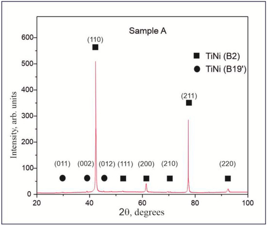
Figure 3.
XRD pattern of Sample A (as prepared TiNi wires before chemical and cryogenic treatment).
The very high bio-integration potential of TiNi-based implants is known to be provided by their surface TiO2 oxide layer, which in the case of TiNi wires is formed during multiple drawing and intermediate annealing procedures. The structure of the produced thin TiNi wires is determined by the way they are prepared, being formed by multiple mechanical and thermal impacts during drawing and annealing. As seen in Figure 4, their surface layer has an inhomogeneous rough structure and consists of individual granules of different sizes which are separated by longitudinal scratches. The latter scratches are of various depths as they are formed due to the impact of separated abrasive granules on the surface during the drawing process through the dies. This is confirmed by the non-straight shape of some scratches, as seen in Figure 4. As the wire was drawn through the die, some abrasive particles may have moved across its surface, which caused the trajectory of the scratch to change (e.g., the trajectory marked with A in Figure 4). The length of the scratch is determined by the total abrasion of such an abrasive particle, as evidenced by the surface scratches in Figure 4 having a beginning and an end (marked with A and B, respectively).
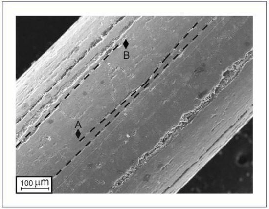
Figure 4.
SEM surface image of TiNi wire with intermediate diameter that demonstrates longitudinal scratches.
During heat treatment of TiNi, its Ti atoms are known to segregate and move toward its free surfaces, leading to the formation of an oxide film based on TiO2 [44,45,46,47]. As a result, depending on the temperature and duration of heat treatment, a surface oxide layer up to 50 µm thick can form in air [44].
The TiNi wires prepared in the present study were also found to have a surface granular layer based on the oxide phase TiO2 (Figure 5). The chemical composition of the surface layer of the sample presented in Figure 5 was determined by EDS to be 55.0, 35.7, and 9.3 at% of O, Ti, and Ni, respectively. The presence of Ni is probably explained by a relatively small thickness of the surface oxide layer of TiO2, which is why Ni atoms could be detected from phases underneath the surface oxide layer. Additionally, the surface layer of the TiNi metal matrix may have a Ni-rich peripheral layer TiNi3, which can also result in an increased Ni value in EDS spectra.
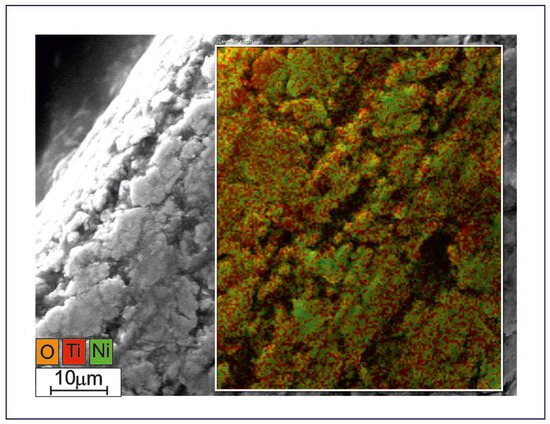
Figure 5.
Surface SE-SEM image combined with EDS map for the prepared TiNi wire (Sample A). Scale bar indicates 10 μm.
Figure 6 exhibits a cross-sectional SEM image (a) and EDS mapping images (b-e) which represent the microstructure of the surface layers and the inner bulk of a TiNi-based thin wire. EDS mapping images demonstrating the distribution of Ti, Ni, and C atoms and their combination (Ti+Ni+C atoms) are presented in panels (b), (c), (d), and (e), respectively. Figure 6b shows an increased Ti content at the wire’s surface, which corresponds to the oxide film based on TiO2. At the same time, there is a decrease in the Ti concentration in the Ni-rich regions (Figure 6c), which corresponds to secondary-phase TiNi3, as well as in the particle structure in the bulk part of the material. Comparison with the C distribution seen in Figure 6d suggests that the observed particles are likely to be based on Ti and C atoms. As a rule, such phases are finely dispersed, up to 500 nm in size, strong, and can initially appear in TiNi-based cast materials from spongy Ti and graphite crucibles where induction melting is carried out. There are also areas of increased C content in Figure 6d seen on the material’s surface and around the longitudinal scratches, which can be explained by the use of carbon lubricants during drawing.
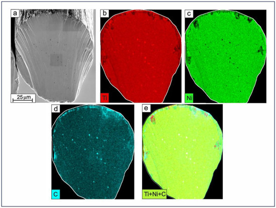
Figure 6.
Cross-sectional SEM image (a) along with corresponding EDS mapping images for Ti (b), Ni (c), C (d), and the combined Ti+Ni+C distribution (e) in the prepared TiNi wire (Sample A). Scale bar indicates 25 μm.
Thus, based on the EDS mapping images, one can draw the following conclusions: (i) The wire has a discrete structure of a surface layer with variable thickness based on TiO2, and a sub-layer underneath which is enriched with C atoms. (ii) There are scratches located on the wire surface which have varying depths, and the oxide layer may be as thick as 0.5–1.5 μm. (iii) The TiNi3 phase appears to be located at the periphery of the metallic bulk of the wire. (iv) There are TiC secondary phase particles and no particles of phase Ti2Ni in the bulk of the produced wires.
Interestingly, no phase Ti2Ni was detected in the present study, while its presence in cast and porous TiNi-based alloys is typically inevitable. Figure 6c shows dark spots at the sites of secondary phase particles which were previously described as having composition TiC. Previously, Bhagyaraj and co-authors showed shearing/fragmentation of Ti2Ni during processing; the areas around them were mostly faceted and assisted in the nucleation of martensite [43]. The matrix close to Ti2Ni particles experienced severe plastic deformation, which led to amorphization [43]. In the context of this work, the plastic deformation during multiple drawing procedures is believed to promote the amorphization of Ti2Ni to such an extent that no phase Ti2Ni could be found in the structure of the produced TiNi wires.
Moreover, based on this finding, as well as the amorphization of TiNi previously reported by Bhagyaraj and co-authors [43], one can assume the nature of deep scratch formation on the surface of TiNi wires. After amorphization of TiNi in the regions around destroyed Ti2Ni particles, the further thinning of the wire moves such areas closer to the periphery, where they can form large defects in the form of pores and cracks.
Figure 7 shows the results of TEM studies of a prepared TiNi wire (40 μm in diameter) and its structure. A lamella-shaped sample was obtained from the sample surface to a depth of 4 μm. In agreement with the above-discussed methods, the results of TEM analyses confirm that the material has a composite structure based on a surface amorphous TiO2 layer (anatase), a crystalline nanostructured matrix based on TiNi (B2), and secondary TiC phase particles.
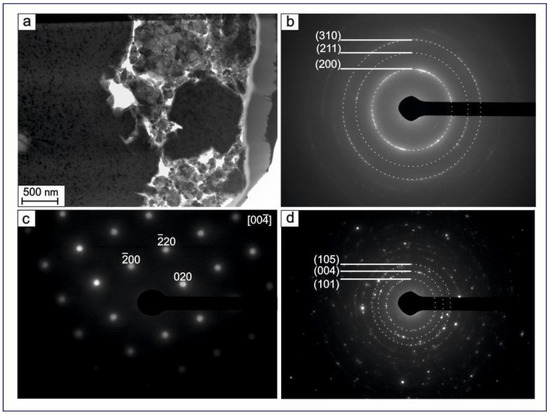
Figure 7.
TEM image of TiNi wire (Sample A) (a); SAED patterns of TiNi (B2) (b), TiO2-anatase (c), and TiC (d). Scale bar in panel (a) indicates 500 nm.
Figure 8a shows the grain microstructure of the TiNi phase with inclusions of secondary phase particles obtained with the R-STEM transmission electron detector in the pseudo-color imaging mode (ColorSTEM). Figure 8b demonstrates Kikuchi pattern lines which confirm the presence of TiC phase particles in the structure of the analyzed TiNi wire. The TiC phase is known to have a cubic structure, belonging to space group with lattice parameter a = 4.3442 Å [48]. The TiC particles were found by TEM analysis to be round-shaped, without straightened boundaries, and having their sizes within the range 0.15–1.7 μm. Similar to Ti3Ni4, the TiC phase was also reported to have finely dispersed coherent particles which significantly increase the ultimate strength and fatigue and wear resistance of their TiNi material, mainly through an increase in the level of internal stresses [49]. Additionally, TiC particles were also shown to contribute to the formation of the R phase, thus lowering some of transformation temperatures [50]. This is expected to have a positive effect on reducing the Young’s modulus values of the TiNi wires produced in this study.
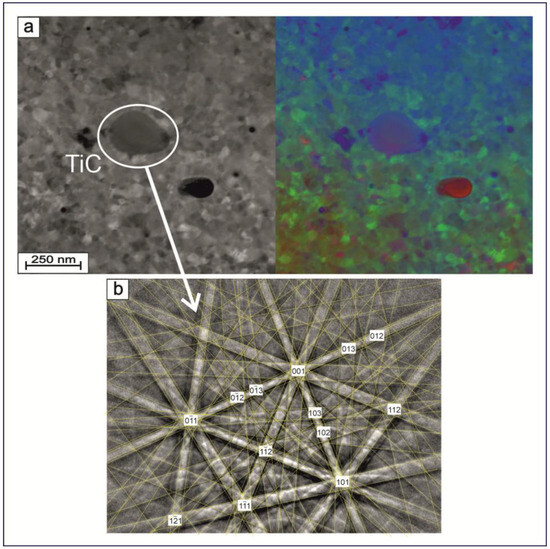
Figure 8.
(a) Cross-sectional R-STEM images recorded in secondary-electron (left) and pseudo-color imaging (right) modes. (b) Kikuchi line patterns of the obtained TiNi wire (Sample A) showing the presence of TiC secondary-phase particles, as indicated in panel (a).
Figure 9 exhibits the boundary structure of an obtained TiNi-based wire with a diameter of 40 μm as well as the histograms of grain size distribution (in the transverse and longitudinal directions). Based on the combination of the TEM, XRD, and EBSD results, no texturing of the microstructure was detected in the obtained TiNi wires. The grains observed within the material have an equiaxed shape and straight boundaries with triple junctions, which indicate their equilibrium state. The average grain size in both directions is seen in Figure 9c,d to be almost the same, having average values around 15–16 nm.
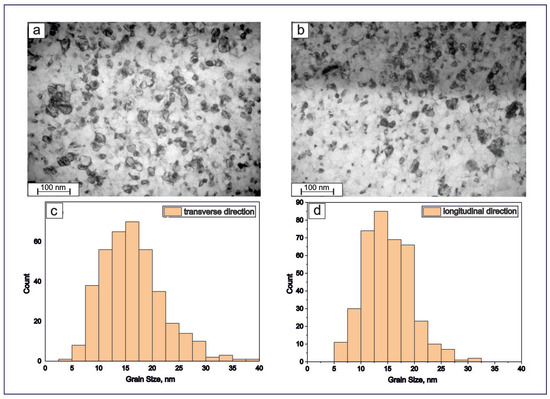
Figure 9.
Cross-sectional TEM images (a,b) and histograms of grain sizes (c,d) of TiNi wires along transverse (a,c) and longitudinal (b,d) directions. As seen in both panels (c,d), the average size is around 15–16 nm.
As a rule, metal grains are known to be refined after thermomechanical treatments, which makes it possible to obtain grains as small as several microns. However, this approach was not reported to result in refined grains with submicron (0.1–1.0 μm) or nanometer (<100 nm) sizes [51]. Such ultra-fine grain sizes usually need some alternative processing methods based on severe plastic deformation [52]. As a rule, to obtain nano-sized metallic grains, specific mechanical processing methods are used, e.g., equal-channel angular pressing (ECAP) [53,54] and mechanical ball milling [55]. Such complex treatments are difficult to apply to the production of implantable structures, since after heating (needed to shape some implants) recrystallization and loss of their nanostructure are often possible. The method of obtaining thin nanostructured wires through drawing offers high productivity due to the use of machines that perform multiple passes through five to six dies. This process results in a significantly faster reduction in wire diameter compared to single-pass drawing. Importantly, drawing is a highly productive and scalable method for producing thin TiNi wires, which can be utilized in textile implants.
Thus, obtaining a nanograined metallic material during its drawing process seems to be a significant result and ensures high functional and mechanical properties of such a material.
Figure 10a presents an XRD pattern of Sample B, where it is clearly seen that cryogenic treatment allowed for the production of thin wires of TiNi with two phases, B2 and B19′. The volume fraction of the high-temperature austenitic phase B2 was found to be 83%, while the fraction of the low-temperature martensitic phase B19′ was 17%. The body-centered crystal structure of TiNi alloys, according to PDF4 # 03-065-5746, is known as the B2 austenitic phase with lattice parameter a = 3.0144 Å, whereas the monoclinic crystal structure B19′ is a martensitic phase with its lattice parameters a = 2.7826 Å, b = 4.2130 Å, c = 4.6198 Å (c/a = 1.660), and β = 96.8° (PDF4 # 00-035-1281).
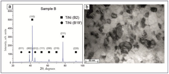
Figure 10.
XRD patterns of produced TiNi wires after cryogenic and chemical treatment of Sample B (a); TEM image of twins of thin wire after modification of Sample B (b).
Figure 10b exhibits a light-field TEM image of a cross-section of Sample B containing B19′ martensite. The submicrostructure of Sample B is represented by B2 austenite grains and B19′ martensite grains with twins. It should be noted that some grains have adjacent boundaries and form clusters, which can be considered as TiNi subgrains. Thus, based on TEM analysis, it can be concluded that, among other processes, the martensitic transformation in cryogenically treated 40 μm thick TiNi nanocrystalline wire proceeded via formation of atomic-scale twin crystals.
Figure 11 compares the stress–strain dependences, σ(ε), of thin TiNi wires for Samples A and B. Each of the two curves demonstrate several distinct sections corresponding to certain stages of deformation: (I) a linear stage of elastic deformation of the high-temperature austenite phase B2 (marked with squares), (II) a yield area associated with the martensitic transition B2→B19′ (marked with triangles), (III) a linear section of strain development under load (marked with circles), and (IV) a stage of intense plastic flow development in the martensitic phase B19′ (marked with diamonds). Table 2 presents the strain–strength characteristics of the studied samples (A and B). The division into sections of the stress–strain dependence of the studied samples corresponds to the stage of deformation development during loading, previously reported elsewhere [56]. The martensitic transformation stage seen in σ(ε) dependence was observed to be followed by the stage of elastic deformation of the martensitic phase. For Sample A it was found to be 5.23%, while for Sample B it was 5.36%. As seen in Figure 11, the qualitative difference in σ(ε) dependences for Samples A and B is mainly in the presence of the subsequent stage of plastic deformation, which is well expressed for Sample B with a thin oxide layer (whose plastic strain was equal to 1.65%, see Table 2). The plastic component in this sample is believed to be realized through the twinning of martensitic plates.
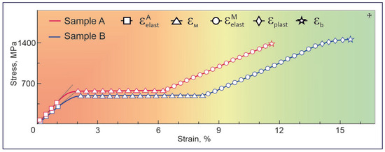
Figure 11.
Stress–strain curves of TiNi wires in Samples A (red) and B (blue).
Table 2.
Mechanical properties of TiNi wires produced in this study.
It is also seen in Table 2 that the material subjected to both chemical and cryogenic treatments (Sample B) demonstrated a decrease in its Young’s modulus (E) value to 27.1 GPa and in its martensitic shear stress (σM) to 485.45 MPa, whereas its martensitic deformation (εM) value increased to 6.15%. One of reasons for such changes might be the appearance of stabilized martensitic phase B19′ in its structure after cryogenic treatment. In accordance with previous reports, the Young’s modulus of martensitic phase B19′, which defines the stiffness of TiNi-based materials, is 20–50 GPa [57,58,59]. Thus, the produced TiNi wires, along with having phases B2 and B19′, are seen to have a lower Young’s modulus.
The additional decrease in Young’s modulus observed for Sample B is believed to be associated with the thinning of the oxide layer. As discussed above, such a surface layer has a complex composite structure, mainly including phases TiO2 and TiNi3 (and possibly a solid solution of titanium in nickel Ni(Ti) between them, in some cases of high-temperature treatment or long exposure time), and serve as a rigid framework during deformation of the sample, which is consistent with the previously published results of Dagdelen and coworkers [60]. The elasticity modulus of each of the above phases is higher than that of the main phase TiNi, which must significantly contribute to the resulting value of Young’s modulus of Sample A. Naturally, after chemical etching and reducing the thickness of the surface oxide layer, the corresponding value of Sample B was reduced.
Figure 12a,b present a textile fabric obtained by machine knitting which is ready to be used as an implantable structure in abdominal hernia treatment or for plastic surgery. The length of the produced web was up to 5 m, with a width of 0.20 m and a cell size of 1.5–2 mm. Due to the structure of the cells (see Figure 12b), which are connected with each other and formed by loops, it is possible to change the size of the web and cells without disturbing the structure of the structure as a whole. Thus, during the operation, the surgeon can both model the material configuration and independently set the size of the cells in longitudinal and transverse directions, as well as the length and width of the textile implant depending on the direction of the web stretching. All these parameters determine the porosity, permeability, linear dimensions, and area of the textile implant.
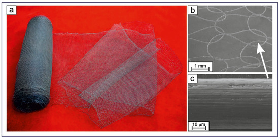
Figure 12.
Photograph (a) and SEM images of produced textile implant based on a 40 μm thick TiNi wire (Sample B) and the microstructure of the thin wire in the textile (b,c). The rolled web in panel (a) is 5 m long and 0.2 m wide.
This textile fabric depicted in Figure 12a was obtained using fine wires subjected to intermediate etching (Sample B). Such intermediate etching was found to smoothen the structure of the surface layer, with both the number of surface granules and their size decreased (Figure 12c), which should reduce the wire’s coefficient of friction. According to previous work [61], the coefficient of friction (f) in wire drawing is a subjective value that depends on the method of its determination. In the present study, f could be estimated from the drawing stress (σD). We found that for the material produced without intermediate etchings (Sample A), its σD was 840 MPa, while for Sample B the σD was 680 MPa. Thus, the coefficient of friction f was estimated to be 0.125 and 0.050 for Samples A and B, respectively. The decrease in the friction coefficient is expected to reduce the number of breaks in both drawing and weaving, which should have a positive effect on both the process of obtaining fine wires and textile items on their basis.
4. Conclusions
This study reports on the development of a novel, low-cost technology for producing thin TiNi wires with enhanced mechanical properties for biomedical use as textiles in reconstructive surgery. TiNi threads as thin as ~40 μm were fabricated by combining wire drawing and acid etching, with the latter chemical treatment used to reduce the thickness of the surface oxide layer periodically after a certain number of drawing procedures. This reduction in oxide layer thickness decreased the friction coefficient of the intermediate material during subsequent drawing procedures, significantly reducing the probability of wire breakage during both production and weaving into textiles. As a final stage, cryogenic treatment was applied to the product to stabilize its martensite phase and thus reduce Young’s modulus. The resulting material, subjected to both chemical and cryogenic treatments, demonstrated a decrease in its Young’s modulus and was based on small TiNi nanograins with average sizes of 15–17 nm. In addition, the as-produced thin TiNi wires were found to be free of Ti2Ni second-phase particles, which is also believed to contribute to their improved mechanical properties. These attributes make the fabricated thin TiNi wires suitable for implantation.
Author Contributions
Conceptualization, N.V.A., H.-T.U., A.V.S. and S.G.A.; methodology, A.V.S., S.A.K. and S.G.A.; investigation, N.V.A., A.V.S., H.-T.U. and S.G.A.; data curation, A.V.S., N.V.A., H.-T.U. and S.A.K.; writing—original draft preparation, N.V.A., H.-T.U. and S.A.K.; writing—review and editing, S.G.A., S.A.K. and A.V.S.; supervision, S.A.K. and S.G.A.; project administration, S.G.A. and N.V.A.; funding acquisition, N.V.A. All authors have read and agreed to the published version of the manuscript.
Funding
The study was supported by the Russian Science Foundation (grant No. 24-29-00735, https://rscf.ru/project/24-29-00735/, accessed on 1 January 2025).
Institutional Review Board Statement
Not applicable.
Informed Consent Statement
Not applicable.
Data Availability Statement
Data are contained within the article.
Acknowledgments
We express gratitude to the Tomsk Regional Core Shared Research Facilities Centre of National Research Tomsk State University. The authors also thank A. Kudryavtsev for the EBSD studies which were carried out using the analytical complex based on the SEM TESCAN MIRA and Oxford Instruments NanoAnalysis EBSD system. The analyses (TEM studies) were carried out using the equipment of the Krasnoyarsk Regional Shared Research Center (Krasnoyarsk Scientific Center, Siberian Branch, Russian Academy of Sciences). Finally, S.A.K. acknowledges support from the Amada Foundation (grant No. AF-2024231-B3).
Conflicts of Interest
The authors declare no conflicts of interest.
References
- Otsuka, K.; Ren, X. Physical metallurgy of Ti–Ni—Based shape memory alloys. Prog. Mater. Sci. 2005, 50, 511–678. [Google Scholar] [CrossRef]
- Potekaev, A.I.; Klopotov, A.A.; Kulagina, V.V.; Solov’eva, Y.V.; Anikeev, S.G. Alloys Based on TiNi in Pre-Transition Low-Stability States; Springer: Berlin/Heidelberg, Germany, 2024; 284p. [Google Scholar] [CrossRef]
- Lobodyuk, V.A.; Estrin, E.I. Martensitic Transformation; Cambridge International Science Publishing Ltd.: Cambridge, UK, 2014. [Google Scholar]
- Bansiddhi, A.; Sargeant, T.D.; Stupp, S.I.; Dunand, D.C. Porous NiTi for bone implants: A review. Acta Biomater. 2008, 4, 773–782. [Google Scholar] [CrossRef] [PubMed]
- Elahinia, M.; Tabesh, M.; Hashemi, M.; Bhaduri, S.B. Manufacturing and processing of TiNi implants: A review. Prog. Mater. Sci. 2012, 57, 911–946. [Google Scholar] [CrossRef]
- Kondoh, K.; Umeda, J.; Soba, R.; Tanabe, Y. Advanced TiNi shape memory alloy stents fabricated by a powder metallurgy route. In Titanium in Medical and Dental Applications; Woodhead Publishing Series in Biomaterials; Woodhead Publishing: Cambridge, UK, 2018; pp. 583–590. [Google Scholar] [CrossRef]
- Anikeev, S.G.; Artyukhova, N.V.; Shabalina, A.V.; Kulinich, S.A.; Hodorenko, V.N.; Kaftaranova, M.I.; Promakhov, V.V.; Gunter, V.E. Preparation of porous TiNi-Ti alloy by diffusion sintering method and study of its composition, structure and martensitic transformations. J. Alloys Compd. 2022, 900, 163559. [Google Scholar] [CrossRef]
- Anikeev, S.G.; Shabalina, A.V.; Kulinich, S.A.; Artyukhova, N.V.; Korsakova, D.R.; Yakovlev, E.V.; Vlasov, V.A.; Kokorev, O.V.; Hodorenko, V.N. Preparation and electron-beam surface modification of novel TiNi material for medical applications. Appl. Sci. 2021, 11, 4372. [Google Scholar] [CrossRef]
- Gucu, A.; Toktas, F.; Eris, C.; Ata, Y.; Turk, T. Nitinol thermoreactive clips for secondary sternal closure in cases of noninfective sternal dehiscence. Texas Heart Inst. J. 2012, 39, 513–516. [Google Scholar]
- Oshida, Y.; Tominaga, T. Nickel-Titanium Materials. Biomedical Applications; De Gruyter: Berlin, Germany, 2020. [Google Scholar] [CrossRef]
- Anikeev, S.G.; Hodorenko, V.N.; Kaftaranova, M.I.; Shabalina, A.V.; Artyukhova, N.V.; Terletskaya, E.N.; Kulinich, S.A.; Pakholkina, S.; Bolshevich, E.A.; Medvedev, Y.A. Porous TiNi material manufactured via self-propagating high-temperature synthesis (SHS) and chemical treatment for ophthalmological implants. Mater. Today Commun. 2024, 40, 110071. [Google Scholar] [CrossRef]
- Jani, J.M.; Leary, M.; Subic, A.; Gibson, M.A. A review of shape memory alloy research, applications and opportunities. Mater. Des. 2014, 56, 1078–1113. [Google Scholar] [CrossRef]
- Cai, S.; Jin, Z.; Zeng, P.; Yang, L.X.; Yan, Y.; Wang, Z.M. Structural optimization and in vivo evaluation of a colorectal stent with anti-migration and anti-tumor properties. Acta Biomater. 2022, 154, 123–134. [Google Scholar] [CrossRef]
- Anikeev, S.G.; Kaftaranova, M.I.; Hodorenko, V.N.; Ivanov, S.D.; Artyukhova, N.V.; Shabalina, A.V.; Kulinich, S.A.; Slizovsky, G.V.; Mokshin, A.V.; Gunther, V.E. TiNi-based material with shape-memory effect for surgical treatment of diseases of small intestine in newborn and young children. J. Funct. Biomater. 2023, 14, 155. [Google Scholar] [CrossRef]
- Gall, K.A.; Tyber, J.A.; Pacaccio, D.J. Osteosynthetic Implants and Methods of Use and Manufacture. U.S. Patent No. 7985222B2, 21 April 2005. [Google Scholar]
- Phukaoluan, A.; Khantachawana, A.; Kaewtatip, P.; Dechkunakorn, S.; Anuwongnukroh, N.; Santiwong, P.; Kajornchaiyakul, J. Comparison of friction forces between stainless orthodontic steel brackets and TiNi wires in wet and dry conditions. Int. Orthod. 2017, 15, 13–24. [Google Scholar] [CrossRef] [PubMed]
- Saito, S.; Wachi, T.; Hanada, S. A new fabrication process of TiNi shape memory wire. Mater. Sci. Eng. A 1993, 161, 91–96. [Google Scholar] [CrossRef]
- Tsuchiya, K.; Hada, Y.; Koyano, T.; Nakajima, K.; Ohnuma, M.; Koike, T.; Todaka, Y.; Umemoto, M. Production of TiNi amorphous/nanocrystalline wires with high strength and elastic modulus by severe cold drawing. Scr. Mater. 2009, 60, 749–752. [Google Scholar] [CrossRef]
- Gunther, S.V.; Anikeev, S.G.; Kim, J.S.; Monogenov, A.N.; Gunther, V.E. The technology of the manufacturing thin wire of TiNi-based alloys by using infrared radiation. KnE Mater. Sci. 2017, 2, 88–97. [Google Scholar] [CrossRef]
- Kaieda, Y. Fabrication of composition-controlled TiNi shape memory wire using combustion synthesis process and the influence of Ni content on phase transformation behavior. Sci. Technol. Adv. Mater. 2003, 4, 239–246. [Google Scholar] [CrossRef]
- Kang, S.B.; Yoon, K.S.; Kim, J.S.; Nam, T.H.; Gjunter, V.E. In vivo result of porous TiNi shape memory alloy: Bone response and growth. Mater. Trans. 2002, 43, 1045–1048. [Google Scholar] [CrossRef]
- Simonovich, A.E.; Fomichev, N.G. Porous TiNi implants in surgery of spine degenerative diseases. KnE Mater. Sci. 2017, 2, 334–342. [Google Scholar] [CrossRef]
- Kokorev, O.V.; Hodorenko, V.N.; Chekalkin, T.L.; Kim, J.S.; Kang, S.B.; Dambaev, G.T.; Gunther, V.E. In vitro and in vivo evaluation of porous TiNi-based alloy as a scaffold for cell tissue engineering. Artif. Cells Nanomed. Biotechnol. 2016, 44, 704–709. [Google Scholar] [CrossRef]
- Shabalina, A.V.; Anikeev, S.G.; Kulinich, S.A.; Artyukhova, N.V.; Vlasov, V.A.; Kaftaranova, M.I.; Hodorenko, V.N.; Yakovlev, E.V.; Pesterev, E.A.; Lukyanenko, A.V.; et al. Combined porous-monolithic TiNi materials surface-modified with electron beam for new-generation rib endoprostheses. J. Funct. Biomater. 2023, 14, 277. [Google Scholar] [CrossRef]
- Zhu, J.; Zeng, Q.; Fu, T. An updated review on TiNi alloy for biomedical applications. Corros. Rev. 2019, 37, 539–552. [Google Scholar] [CrossRef]
- Manivasagam, G.; Dhinasekaran, D.; Rajamanickam, A. Biomedical implants: Corrosion and its prevention—A review. Recent Pat. Corros. Sci. 2010, 2, 40–54. [Google Scholar] [CrossRef]
- Denisenko, V.; Gain, Y.M.; Buhtarevich, S.P.; Rubanik, V.V.; Rubanik, V.; Tomchina, A.V.; Erushevich, A.V.; Shkudnov, A.A.; Shappo, G.M.; Veremey, Y.I.; et al. Application of self-expanding titanium nickelide stents of Belorussian manufacture in the treatment of stenotic colorectal cancer. Endosk. Khirurgiya 2017, 23, 15. [Google Scholar] [CrossRef]
- Lima Miranda, R.; Zamponi, C.; Quandt, E. Fabrication of TiNi thin film stents. Smart Mater. Struct. 2009, 18, 104010. [Google Scholar] [CrossRef]
- Moravej, M.; Mantovani, D. Biodegradable metals for cardiovascular stent application: Interests and new opportunities. Int. J. Mol. Sci. 2011, 12, 4250–4270. [Google Scholar] [CrossRef]
- Filip, P.; Lausmaa, J.; Musialek, J.; Mazanec, K. Structure and surface of TiNi human implants. Biomaterials 2001, 22, 2131–2138. [Google Scholar] [CrossRef]
- Artyukhova, N.; Yasenchuk, Y.; Chekalkin, T.; Gunther, V.; Kim, J.S.; Kang, J.H. Structure and properties of porous TiNi(Co, Mo)-based alloy produced by reaction sintering. Smart Mater. Struct. 2016, 25, 107003. [Google Scholar] [CrossRef]
- Radkevich, A.; Gantimurov, A.; Zhiglov, N.; Podgorny, V.; Zhiglov, D.; Zhiglov, A.; Gunther, V. Application of TiNi Dental Implants With Permeable Porosity in Patients Rehabilitation with Different Adentia Options. KnE Mater. Sci. 2017, 2, 211–218. [Google Scholar] [CrossRef]
- Olesov, E.; Bronstein, D.; Lerner, A.; Zaslavsky, R.; Shmatov, K. Electrochemical Interaction of TiNi-Based Implant With Overlay Denture. KnE Mater. Sci. 2017, 2, 448–452. [Google Scholar] [CrossRef]
- Vautrin, A.; Aw, J.; Attenborough, E.; Varga, P. Fatigue life of 3D-printed porous titanium dental implants predicted by validated finite element simulations. Front. Bioeng. Biotechnol. 2023, 11, 1240125. [Google Scholar] [CrossRef]
- Gil, F.J.; Planell, J.A. Effect of copper addition on the superelastic behavior of Ni-Ti shape memory alloys for orthodontic applications. J. Biomed. Mater. Res. 1999, 48, 682–688. [Google Scholar] [CrossRef]
- Shvedova, M.; Dambaev, G.; Vusyk, A.; Skidanenko, V.; Anfinogenova, Y. TiNi-Based Mesh Implant Sternal Resynthesis in Patients With Postoperative Sterno-Mediastinitis. KnE Mater. Sci. 2017, 2, 273–279. [Google Scholar] [CrossRef]
- Abd-Elaziem, W.; Mohammed, M.M.; Yehia, H.M.; Sebaey, T.A.; Khan, T. Porous titanium for medical implants. Multidiscip. Mater. Chron. 2024, 1, 1–18. [Google Scholar] [CrossRef]
- Chen, J.; Chen, L.; Li, W.; Swain, M.; Li, Q. Porous Titanium Implant and Micro-CT Based Characterization of Sub-Surface Morphology. In Proceedings of the 8th Pacific Rim International Congress on Advanced Materials and Processing, Waikoloa, HI, USA, 4–9 August 2013; pp. 1579–1586. [Google Scholar]
- Khmelevskaya, I. Medical applications of TiNi-based shape memory alloys in Russia. In Proceedings of the Scientific Proceedings of IX International Congress “Machines, Technologies, Materials”, Varna, Bulgaria, 19–21 September 2012; Volume 3, pp. 68–71. [Google Scholar]
- Birleanu, C.; Pustan, M.; Cioaza, M.; Molea, A.; Popa, F.; Contiu, G. Effect of TiO2 nanoparticles on the tribological properties of lubricating oil: An experimental investigation. Sci. Rep. 2022, 12, 5201. [Google Scholar] [CrossRef] [PubMed]
- Ng, C.W.; Mahmud, A.S.; Ahmad, M.N.; Razali, M.F.; Liu, Y. Estimation of titanium oxide layer thickness on thermally oxidized NiTi alloy based on color variations. Materialwiss. Werkstofftech. 2022, 53, 47. [Google Scholar] [CrossRef]
- Ashby, M.F. Materials Selection in Mechanical Design, 1st ed.; Butterworth-Heinemann: Oxford, UK, 2011; 646p. [Google Scholar]
- Bhagyaraj, J.; Ramaiah, K.V.; Saikrishna, C.N.; Bhaumik, S.K.; Gouthama. Behaviour and effect of Ti2Ni phase during processing of NiTi shape memory alloy wire from cast ingot. J. Alloys Compd. 2013, 581, 344–351. [Google Scholar] [CrossRef]
- Mahmud, A.; Wu, Z.; Zhang, J.; Liu, Y.; Yang, H. Surface oxidation of NiTi and its effects on thermal and mechanical properties. Intermetallics 2018, 103, 52–62. [Google Scholar] [CrossRef]
- Satow, T.; Isano, T.; Honma, T. The high temperature oxidation of intermetallic compound TiNi. J. Jpn. Inst. Met. 1974, 38, 242–246. (In Japanese) [Google Scholar] [CrossRef][Green Version]
- Chu, C.L.; Wu, S.K.; Yen, Y.C. Oxidation behavior of equiatomic TiNi alloy in high temperature air environment. Mater. Sci. Eng. A 1996, 216, 193–200. [Google Scholar] [CrossRef]
- Firstov, G.S.; Vitchev, R.G.; Kumar, H.; Blanpain, B.; Van Humbeeck, J. Surface oxidation of NiTi shape memory alloy. Biomaterials 2002, 23, 4863–4871. [Google Scholar] [CrossRef]
- Zhou, Y.C.; Wang, X.H.; Sun, Z.M.; Chena, S.Q. Electronic and structural properties of the layered ternary carbide Ti3AlC2. J. Mater. Chem. 2001, 11, 2335–2339. [Google Scholar] [CrossRef]
- Ye, H.Z.; Liu, R.; Li, D.Y.; Eadie, R. Development of a new wear-resistant material: TiC/TiNi composite. Scr. Mater. 1999, 41, 1039–1045. [Google Scholar] [CrossRef]
- Mari, D.; Dunand, D.C. NiTi and NiTi-TiC composites: Part 1. transformation and thermal cycling behavior. Met. Mater. Trans. A 1995, 26, 2833–2847. [Google Scholar] [CrossRef]
- Valiev, R.Z.; Raab, G.J.; Botckin, A.V.; Dubinina, S.V. Ultra-fine grained metals and alloys receprion with plastic deformation methods: New points of view at technologies wworking up. Izv. Ferr. Metal. 2012, 55, 54–57. (In Russian) [Google Scholar] [CrossRef][Green Version]
- Valiev, R.Z.; Estrin, Y.; Horita, Z.; Langdon, T.G.; Zechetbauer, M.J.; Zhu, Y.T. Producing bulk ultrafine-grained materials by severe plastic deformation. JOM 2006, 58, 33–39. [Google Scholar] [CrossRef]
- Khmelevskaya, I.Y.; Karelin, R.D.; Prokoshkin, S.D.; Andreev, V.A.; Yusupov, V.S.; Perkas, M.M.; Prosvirnin, V.V.; Shelest, A.E.; Komarov, V.S. Effect of the quasi-continuous equal-channel angular pressing on the structure and functional properties of Ti–Ni-based shape-memory alloys. Phys. Met. Metallogr. 2017, 118, 279–287. [Google Scholar] [CrossRef]
- Karelin, R.; Komarov, V.; Khmelevskaya, I.; Cherkaso, V.; Andreev, V.; Yusupov, V.; Prokoshkin, S. Effect of temperature-deformation regimes of equal channel angular pressing in core-shell mode on the structure and properties of near-equiatomic titanium nickelide shape memory alloy. J. Alloys Compd. 2024, 1005, 176071. [Google Scholar] [CrossRef]
- El-Eskandarany, M.S.; Al-Hazza, A.; Al-Hajji, L.A.; Ali, N.; Al-Duweesh, A.A.; Banyan, M.; Al-Ajmi, F. Mechanical milling: A superior nanotechnological tool for fabrication of nanocrystalline and nanocomposite materials. Nanomaterials 2021, 11, 2484. [Google Scholar] [CrossRef]
- Lotkov, A.; Grishkov, V.; Timkin, V.; Baturin, A.; Zhapova, D. Yield stress in titanium nickelide-based alloys with thermoelastic martensitic transformations. Mater. Sci. Eng. A. 2019, 744, 74–78. [Google Scholar] [CrossRef]
- Rajagopalan, S.; Little, A.L.; Bourke, M.A.M.; Vaidyanathan, R. Elastic modulus of shape-memory NiTi from in situ neutron diffraction during macroscopic loading, instrumented indentation, and extensometry. Appl. Phys. Lett. 2005, 86, 081901. [Google Scholar] [CrossRef]
- Qiu, S.; Clausen, B.; Padula II, S.A.; Noebe, R.D.; Vaidyanathan, R. On elastic moduli and elastic anisotropy in polycrystalline martensitic NiTi. Acta Mater. 2011, 59, 5055–5066. [Google Scholar] [CrossRef]
- Li, K.F.; Li, M.; Zhao, Y.; Shan, W.K.; Cao, Y.; Guo, D. Achieving ultralow elastic modulus in TiNi alloy by controlling nanoscale martensite phase. Mater. Lett. 2018, 233, 282–285. [Google Scholar] [CrossRef]
- Dagdelen, F.; Ercan, E. The surface oxidation behavior of Ni–45.16%Ti shape memory alloys at different temperatures. J. Therm. Anal. Calorim. 2014, 115, 561–565. [Google Scholar] [CrossRef]
- Guryanov, G.N. Methods for determining the coefficient of friction during drawing of a round solid profile. Zavod. Lab. Diagn. Mater. 2016, 82, 60–68. Available online: https://www.zldm.ru/jour/article/view/293/294 (accessed on 1 January 2025).


Disclaimer/Publisher’s Note: The statements, opinions and data contained in all publications are solely those of the individual author(s) and contributor(s) and not of MDPI and/or the editor(s). MDPI and/or the editor(s) disclaim responsibility for any injury to people or property resulting from any ideas, methods, instructions or products referred to in the content. |
© 2025 by the authors. Licensee MDPI, Basel, Switzerland. This article is an open access article distributed under the terms and conditions of the Creative Commons Attribution (CC BY) license (https://creativecommons.org/licenses/by/4.0/).