Article

Effect of Anti-Bending Bars on Vertical Vibrations of Passenger Carriage Body

by
Ioana-Izabela Apostol
,
Traian Mazilu
* and
Mădălina Dumitriu
*
Department of Railway Vehicles, National University of Science and Technology Politehnica Bucharest, 060042 Bucharest, Romania
*
Authors to whom correspondence should be addressed.
Technologies 2025, 13(2), 73; https://doi.org/10.3390/technologies13020073
Submission received: 18 December 2024 / Revised: 7 February 2025 / Accepted: 8 February 2025 / Published: 10 February 2025

Abstract

:
High-speed passenger carriages with a long and light carriage body are sensitive to vertical vibration because the bending mode eigenfrequency falls within the most sensible frequency interval for the human being. Anti-bending bars (ABBs) are a passive means to raise the eigenfrequency of the bending mode of the carriage body beyond the sensitive limit, ameliorating ride comfort. ABBs are two bars fixed via vertical supports under the carriage chassis on the longitudinal beams. ABBs resist the bending of the carriage body and can, therefore, increase the bending eigenfrequency beyond the sensitive limit, as necessary. In this paper, a new model for the ABBs, which takes into account the longitudinal stiffness of the ABBs, the three-direction stiffness of the fastening between the ABBs and the vertical supports and the vertical vibration modes of the ABBs via the Euler–Bernoulli beam theory and modal analysis, is incorporated in the 10 degrees of freedom model of a passenger carriage; this is to study the effect of the ABBs upon the running behaviour and ride comfort according to the specific regulations in the field. First, the frequency response functions (FRFs) of the passenger carriage with an ABB system are calculated and analysed, and then, the root mean square (r.m.s.) acceleration and the comfort index are evaluated in the carriage body centre in the context of a parametric study. The longitudinal stiffness of the fastening is critical to ensure the effectiveness of the ABB system. However, the effect of decreasing in the longitudinal stiffness of the fastening can be compensated by adopting longer ABBs.

1. Introduction

Passenger carriages are designed to meet the requirements related to running behaviour and ride comfort, according to the specific regulations [1,2]. This task is challenging to accomplish when it comes to high-speed passenger carriages that can experience disturbing vertical structural vibrations. This type of vehicle is often provided with long and light carriage bodies that favour the transmission of vertical vibrations in the frequency range of the maxim sensitivity of the human being, situated around 8 Hz, affecting vertical ride comfort [3,4,5]. This happens because the eigenfrequency of the first bending mode of the carriage body can lower to 6–10 Hz due to its slender and light structure.
There are two ways to ameliorate vertical ride comfort due to the vibration of the high-speed passenger carriages, namely the isolation of the carriage body from vibration [6,7,8,9,10] and the attenuation of its structural vibration [11,12,13,14,15].
In both situations, passive, semi-active and active means can be used. Passive means imply using passive components, such as springs and dampers, or simple devices of mechanical nature that are cheap and safe to operate [16,17,18,19,20]. Active and semi-active means the use of actuators operating under sophisticated systems of command and control which are costly [6,8,21,22,23,24].
The structural vibration of the carriage body can be excited by track irregularities depending on the train speed and the spacing of the axles in the vehicle [25,26]. At relatively high speeds, the structural vibration of the carriage body exhibits resonance effects, which has a negative impact on the vertical ride comfort. It is difficult to mitigate these effects through the isolation of the carriage body by means of passive secondary suspension, as this is designed to isolate the rigid motion of the carriage body and has little effect on its structural vibration. From this perspective, passive dynamic vibration absorbers, or other dedicated mechanical devices mounted on the chassis of the carriage body, appear to be more effective [27,28,29]. Active and semi-active technologies can be applied in secondary suspension or primary suspension to control both the rigid modes and the structural vibration of the carriage body [30]. Semi-active primary suspensions can be highly effective when an adequate controller is used, such as the Linear–Square–Gaussian controller [31]. Semi-active suspensions have the advantage of being less complex and less expensive than active suspensions. They are also safer and more reliable.
The ABB system represents a passive means to improve ride comfort in high-speed rail vehicles with a light and long carriage body (Figure 1) [29]. Each longeron of the carriage body chassis is provided with two vertical supports bearing a bar. The two ABBs work in the longitudinal direction as springs that act upon the vertical supports by reaction forces depending on how the carriage body bends. Reaction forces determine longitudinal forces and bending moments in the neutral axis of the carriage body. Bending moments oppose the carriage body bending, increasing the bending stiffness and the eigenfrequency of its first bending mode.
To explore the ABBs practicability to improve ride comfort, the seven degrees of freedom model of a passenger carriage with an ABB system moving along a rigid track has been used to calculate the comfort index [29]. The carriage body was represented as an equivalent Euler–Bernoulli beam, and the bounce motion, pitch motion and first bending mode have been considered using the modal analysis technique. The ABBs have been modelled by simple longitudinal springs related to the vertical supports, neglecting their mass and the possibility to move in the vertical direction. This ABBs model is termed hereafter as ABBs–spring model. The passenger carriage model incorporates the two bogies considered as rigid objects moving in the vertical plane (bounce and pitch) and the primary and secondary suspension.
The parameters of the ABBs (diameter and length) must meet two conditions related to the convenient increase in the carriage body bending frequency and the avoidance of interference between the carriage body bending and the ABBs bending. To meet the last condition, it is necessary that the bending frequency of the ABBs be twice as high as the bending frequency of the carriage body with ABBs, thus resulting in the limitation of the length of the ABBs [29].
The capability of the ABBs system to raise the frequency of the first bending mode of the carriage body has been tested in laboratory conditions using a scale demonstrator [32,33].
To refine the ABBs representation, a new model has been elaborated to consider the three-directional stiffness of the fastening between the ABBs and the vertical supports and the vertical motion of the ABBs [34]. The ABBs new model has been integrated into the model of the carriage body–secondary suspension system maintaining the above carriage body model. The fastening between the ABBs and vertical supports is modelled as three springs, two for vertical and longitudinal translation and one for rotation in the vertical–longitudinal plane. The ABBs are considered as Euler–Bernoulli beams connected to the fastening springs. Applying the modal analysis technique, the bounce, pitch and first bending mode of the carriage body and the ABBs have been retained to facilitate the analysis of the influence of the fastening stiffness on the eigenfrequency of the vibration modes of the carriage body and ABBs.
In this paper, the new model of ABBs described above [34] is integrated in the entire model of a passenger carriage resulting in a 10 degrees of freedom new model of the passenger carriage with ABBs. The advantages of the new model of a passenger carriage with ABBs consist of the possibility to consider the three-directional stiffness of the fastening and the bending vibration of the ABBs. FRFs of the carriage body and ABBs are computed first, and the influence of the fastening stiffness on the vibration behaviour of the carriage body and ABBs is investigated. Subsequently, the new model of the passenger carriage with ABBs running on a track with random irregularity is used to calculate the r.m.s. acceleration (hereafter, simply referred to as acceleration) and the comfort index to point out the objectives of this paper: to evaluate the effect of the fastening stiffness and the bending vibration of the ABBs on the running behaviour and ride comfort in the carriage body and to identify the possibility to improve them.

2. Mechanical Model of the Passenger Carriage with an ABB System and Governing Equations

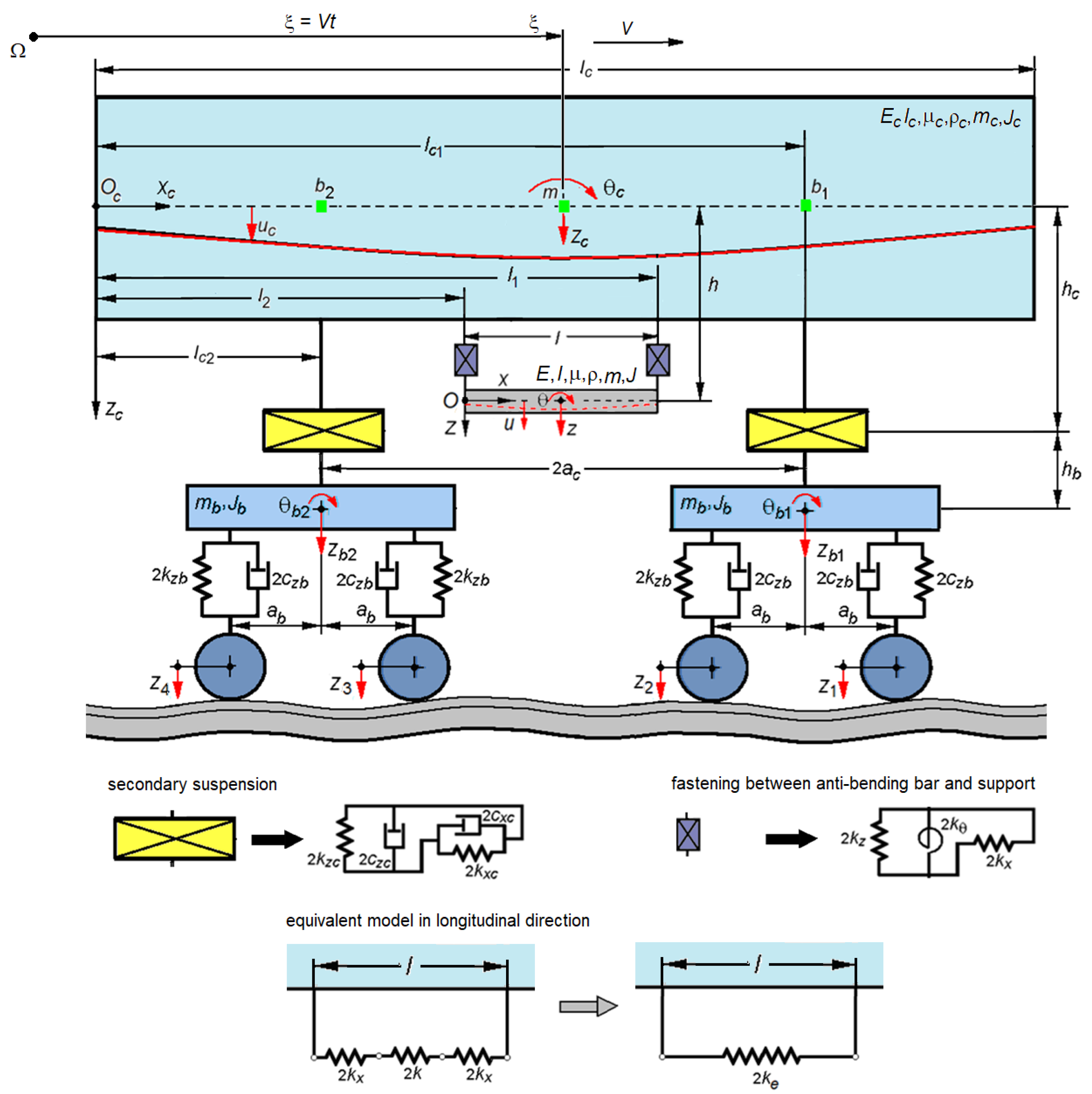
2.1. Mechanical Model

Figure 2 presents the mechanical model of the passenger carriage with an ABB system running at constant speed V on a rigid track affected by vertical irregularity exciting the vehicle vibration. The passenger carriage position is related to the static reference frame Ωξ, so that the position of the carriage body centre is ξ = Vt, where t stands for time.
Both the passenger carriage and track are supposed as symmetrical structures in relation to the longitudinal vertical plane. At the same time, the passenger carriage is symmetrical in relation to a transverse vertical plane that contains the centre of gravity of the carriage body. Vehicle model incorporates the carriage body featured with an ABB system resting on the secondary suspension, and two bogies that include the primary suspension and four wheelsets.
The carriage body and the two ABBs are modelled as uniform free-free Euler–Bernoulli beams. The parameters for the carriage body are the mass per length unit ρc, the equivalent bending stiffness EcIc, the structural damping coefficient μc, the carriage body length lc, the distances from the left end of the carriage body to the elements of the secondary suspension, lc1 and lc2, and the vehicle wheelbase, 2ac. The parameters for the ABBs are the diameter d, the mass per length unit ρ, the bending stiffness EI, the structural damping coefficient μ, the length l, the distances from the left end of the carriage body to the vertical supports, l1 and l2, and the distance from the ABBs axis to the neutral axis of the carriage body h. In the longitudinal direction, the ABBs are considered as elastic elements of stiffness, k, each.
k = π d 2 E 4 l .
The carriage body motion is described by the function uc(xc, t) representing the vertical displacement of the xc carriage body section at the time t in respect to the moving reference frame Ocxczc. The two ABBs move together and their motion is described by the function u(x, t)—the vertical displacement of the section x at the time t with respect to the moving reference Oxz.
Fastening between the ABBs and the vertical supports are modelled using three elastic elements to each bar end working in vertical and longitudinal directions and, respectively, rotation in the vertical–longitudinal plane. The parameters for the fastening are the vertical stiffness kz, the longitudinal stiffness kx and the rotational stiffness kθ.
Longitudinal elastic elements of the fastening work with the ABBs as equivalent elastic elements of equivalent stiffness 2ke (Figure 2).
2 k e = 2 k K 2 + K ,
where the proportional factor K is the ratio between the longitudinal stiffness of the fastening and the stiffness of the bar.
K = k x k .
The secondary suspension is modelled using two Kelvin–Voigt systems, one for the vertical direction and other one for the longitudinal direction. The first Kelvin–Voigt system represents the actual elements of the secondary suspension, and the second Kelvin–Voigt system models the longitudinal bar system transmitting the traction/braking force between the carriage body and the two bogies. Parameters for the secondary suspension model are the vertical stiffness kzc, the vertical damping constant czc, the longitudinal stiffness kxc and the longitudinal damping constant cxc, the distance between the longitudinal bar system and the carriage body neutral axis hc, and the distance between the longitudinal bar system and the bogie mass centre hb.
The two bogies are modelled as a rigid body with two degrees of freedom: vertical translation, termed the bogie bounce, and vertical–longitudinal rotation, termed the bogie pitch. Parameters for the bogie model are the mass mb, the mass moment of inertia Jb and the wheelbase 2ab.
The bogie displacement in the vertical plane is described by the functions zb1(t) and zb2(t) for the bounce motion, and θb1(t) and θb2(t) for the pitch rotation.
The primary suspension is modelled with the help of a Kelvin–Voigt system and its parameters are the vertical stiffness kzb and the damping constant czb.
Vertical vibration of the vehicle is excited by the displacement of the wheelsets, zo1÷4(t), which equals the track irregularity corresponding to each wheelset.

2.2. Equations of Motion

The equation of motion for the carriage body can be written according to the Euler–Bernoulli beam theory
E c I c 4 u c ( x c , t ) x c 4 + μ c I c 5 u c ( x c , t ) x c 4 t + ρ c 2 u c ( x c , t ) t 2 = i = 1 2 F z c i δ ( x c l c i ) + F z i δ ( x c l i ) i = 1 2 ( M i F x i h ) δ ( x c l i ) ,
where δ(.) is the unit impulse function, Fzci are the forces in the secondary suspension, and Fxi, Fzi and Mi are the forces and the moments in the elastic elements of the fastenings.
F z c i = 2 c z c u c ( l c i , t ) t z ˙ b i 2 k z c u c ( l c i , t ) z b i ,
F x 1 , 2 = ± 2 k e h u c ( l 1 , t ) x c u c ( l 2 , t ) x c , F z 1 = 2 k z u c ( l 1 , t ) u ( l , t ) , F z 2 = 2 k z u c ( l 2 , t ) u ( 0 , t ) , M 1 = 2 k θ u c ( l 1 , t ) x c u ( l , t ) x , M 2 = 2 k θ u c ( l 2 , t ) x c u ( 0 , t ) x .
Similarly, the equation of motion of the ABBs can be read as follows:
2 E I 4 u ( x , t ) x 4 + 2 μ I 5 u ( x , t ) x 4 t + 2 ρ 2 u ( x , t ) t 2 = F z 1 δ ( x l ) F z 2 δ ( x ) + M 1 δ ( x l ) + M 2 δ ( x ) .
Equations of motion (4) and (7) can be transformed by the modal analysis method to obtain the equations of motion for the rigid modes (bounce and pitch motions) and the first bending mode for both the carriage body and ABBs. For this aim, the displacements of the carriage body and ABBs are taken as follows:
u c ( x c , t ) = z c ( t ) + x c l c 2 θ c ( t ) + Y c ( x c ) T c ( t )
u ( x , t ) = z ( t ) + x l 2 θ ( t ) + Y ( x ) T ( t ) ,
where zc(t) and θc(t) are the bounce and pitch motions of the carriage body, z(t) and θ(t) are the same motion components for the ABBs, Tc(t) and Yc(xc) are the time coordinate and the eigenfunction of the first bending mode of the carriage body, and T(t) and Y(x) are the same functions for the first bending mode of the ABBs.
Eigenfunctions have the following shape:
Y c ( x c ) = sin ( α c x c ) + sinh ( α c x c ) sin ( α c l c ) sinh ( α c l c ) cos ( α c l c ) cosh ( α c l c ) cos ( α c x c ) cosh ( α c x c ) ,
Y ( x ) = sin ( α x ) + sinh ( α x ) sin ( α l ) sinh ( α l ) cos ( α l ) cosh ( α l ) cos ( α x ) cosh ( α x ) ,
where α c = p c 2 ρ c E c I c 4 and α = p 2 ρ E I 4 are the solutions to the characteristic equations
cos α c l c cosh α c l c 1 = 0
and
cos α l cosh α l 1 = 0 ,
where pc and p are the eigenvalues of the first bending mode of the carriage body and ABBs.
In line with the above, the following are equations of motion result:
-
For the bounce motion,
m c z ¨ c + 4 c z c z ˙ c + 4 ( k z c + k z ) z c + 4 ε c z c T ˙ c + 4 ( ε k z c + β k z ) T c 4 k z z 4 γ k z T 2 c z c z ˙ b 1 + z ˙ b 2 2 k z c z b 1 + z b 2 = 0 ,
2 m z ¨ + 4 k z z + 4 γ k z T 4 k z z c 4 β k z T c = 0 ,
-
For the pitch motion,
J c θ ¨ c + 2 c z c a c [ 2 a c θ ˙ c ( z ˙ b 1 z ˙ b 2 ) ] + 2 k z c a c [ 2 a c θ c ( z b 1 z b 2 ) ] + 2 c x c h c [ 2 h c θ ˙ c + h b ( θ ˙ b 1 + θ ˙ b 2 ) ] + 2 k x c h c [ 2 h c θ c + h b ( θ b 1 + θ b 2 ) ] + ( l 2 k z + 4 k θ ) θ c ( l 2 k z + 4 k θ ) θ = 0
2 J θ ¨ + ( l 2 k z + 4 k θ ) θ ( l 2 k z + 4 k θ ) θ c = 0 ,
-
For the first bending mode,
m m c T ¨ c + ( c m c + 4 ε 2 c z c ) T ˙ c + ( k m c + 4 ε 2 k z c + 4 β 2 k z + 4 β 2 k θ + 8 β 2 h 2 k e ) T c + 4 ε c z c z ˙ c + ( 4 ε k z c + 4 β k z ) z c 4 β k z z 4 ( β γ k z β γ k θ ) T + 2 c x c h c λ [ 2 h c λ T ˙ c + h b ( θ ˙ b 1 θ ˙ b 2 ) ] + 2 k x c h c λ [ 2 h c λ T c + h b ( θ b 1 θ b 2 ) ] 2 ε c z c ( z ˙ b 1 + z ˙ b 2 ) 2 ε k z c ( z b 1 + z b 2 ) = 0 .
2 m m T ¨ + 2 c m T ˙ + 2 ( k m + 2 γ 2 k z + 2 γ 2 k θ ) T + 4 γ k z z 4 γ k z z c 4 ( β γ k z β   γ   k θ ) T c = 0 ,
where mmc, cmc and kmc are the modal mass, modal damping and modal stiffness of the first bending mode of the carriage body, and mm, cmc and km are the same parameters for the first bending mode of the ABBs.
m m c = ρ c 0 l c Y c 2 ( x c ) d x c ,   c m c = μ c I c 0 l c d 2 Y c ( x c ) d x c 2 2 d x c ,   k m c = E c I c 0 l c d 2 Y c ( x c ) d x c 2 2 d x c ,
m m = ρ 0 l Y 2 ( x ) d x ,   c m = μ I 0 l d 2 Y ( x ) d x 2 2 d x ,   k m = E I 0 l d 2 Y ( x ) d x 2 2 d x .
The next symbols are introduced in Equations (14)–(19).
Y c ( l c 1 ) = Y c ( l c 2 ) = ε ,   Y c ( l 1 ) = Y c ( l 2 ) = β , d Y c ( l c 1 ) d x c = d Y c ( l c 2 ) d x c = ε ,   d Y c ( l 1 ) d x c = d Y c ( l 2 ) d x c = β , Y ( 0 ) = Y ( l ) = γ ,   d Y ( 0 ) d x = d Y ( l ) d x = γ .
Applying the laws of mechanics, the equations of motion of the bogie chassis are obtained:
-
For the bounce motion,
m b z ¨ b 1 + 4 c z b z ˙ b 1 + 4 k z b z b 1 + 2 c z c ( z ˙ b 1 z ˙ c a c θ ˙ c ε T ˙ c ) + 2 k z c ( z b 1 z c a c θ c ε T c ) = 2 c z b ( z ˙ 1 + z ˙ 2 ) + 2 k z b ( z 1 + z 2 ) ,
m b z ¨ b 2 + 4 c z b z ˙ b 2 + 4 k z b z b 2 + 2 c z c ( z ˙ b 2 z ˙ c + a c θ ˙ c ε T ˙ c ) + 2 k z c ( z b 2 z c + a c θ c ε T c ) = 2 c z b ( z ˙ 3 + z ˙ 4 ) + 2 k z b ( z 3 + z 4 ) ,
-
For the pitch motion,
J b θ ¨ b 1 + 4 c z b a b 2 θ ˙ b 1 + 4 k z b a b 2 θ b 1 + 2 c x c h b [ h b θ ˙ b 1 + h c ( θ ˙ c + λ T ˙ c ) ] + 2 k x c h b [ h b θ b 1 + h c ( θ c + λ T c ) ] = 2 c z b a b ( z ˙ 1 z ˙ 2 ) + 2 k z b a b ( z 1 z 2 ) ,
J b θ ¨ b 2 + 4 c z b a b 2 θ ˙ b 2 + 4 k z b a b 2 θ b 2 + 2 c x c h b [ h b θ ˙ b 2 + h c ( θ ˙ c λ T ˙ c ) ] + 2 k x c h b [ h b θ b 2 + h c ( θ c λ T c ) ] = 2 c z b a b ( z ˙ 3 z ˙ 4 ) + 2 k z b a b ( z 3 z 4 ) .
Next, the passenger carriage without an ABB system and the passenger carriage with an ABB system–spring model are considered for comparison.
Equations of motion of the vehicle without an ABB system are obtained by inserting ke = 0, kz = 0 and kθ = 0 in Equations (14), (16) and (18):
-
For the bounce motion,
m c z ¨ c + 4 c z c z ˙ c + 4 k z c z c + 4 ε c z c T ˙ c + 4 ε k z c T c 2 c z c z ˙ b 1 + z ˙ b 2 2 k z c z b 1 + z b 2 = 0 ,
-
For the pitch motion,
J c θ ¨ c + 4 a c 2 c z c θ ˙ c + 4 a c 2 k z c θ c 2 a c c z c z ˙ b 1 z ˙ b 2 2 a c k z c z b 1 z b 2 + 2 c x c h c [ 2 h c θ ˙ c + h b ( θ ˙ b 1 + θ ˙ b 2 ) ] + 2 k x c h c [ 2 h c θ c + h b ( θ b 1 + θ b 2 ) ] = 0 ,
-
For the first bending mode,
m m c T ¨ c + ( c m c + 4 ε 2 c z c ) T ˙ c + ( k m c + 4 ε 2 k z c ) T c + 4 ε c z c z ˙ c + 4 ε k z c z c + 2 c x c h c λ [ 2 h c λ T ˙ c + h b ( θ ˙ b 1 θ ˙ b 2 ) ] + 2 k x c h c λ [ 2 h c λ T c + h b ( θ b 1 θ b 2 ) ] 2 ε c z c ( z ˙ b 1 + z ˙ b 2 ) 2 ε k z c ( z b 1 + z b 2 ) = 0 ,
and adding Equations (23)–(26).
Equations of motion of the vehicle with an ABB system–spring model are obtained by inserting ke = k, kz = 0 and kθ = 0 in Equations (14), (16) and (18).
-
For the bounce motion,
m c z ¨ c + 4 c z c z ˙ c + 4 k z c z c + 4 ε c z c T ˙ c + 4 ε k z c T c 2 c z c z ˙ b 1 + z ˙ b 2 2 k z c z b 1 + z b 2 = 0 ,
-
For the pitch motion,
J c θ ¨ c + 4 a c 2 c z c θ ˙ c + 4 a c 2 k z c θ c 2 a c c z c z ˙ b 1 z ˙ b 2 2 a c k z c z b 1 z b 2 = 0 ,
-
For the first bending mode,
m m c T ¨ c + ( c m c + 4 ε 2 c z c ) T ˙ c + ( k m c + 4 ε 2 k z c + 8 β 2 h 2 k ) T c + 4 ε c z c z ˙ c + 4 ε k z c z c + 2 c x c h c λ [ 2 h c λ T ˙ c + h b ( θ ˙ b 1 θ ˙ b 2 ) ] + 2 k x c h c λ [ 2 h c λ T c + h b ( θ b 1 θ b 2 ) ] 2 ε c z c ( z ˙ b 1 + z ˙ b 2 ) 2 ε k z c ( z b 1 + z b 2 ) = 0 ,
and adding Equations (23)–(26).
Returning to the equations of motion of the passenger carriage model, namely Equations (14)–(19) and (23)–(26), it is proposed to write them in matrix form:
M q ¨ + C q ˙ + K q = P z ˙ + R z ,
where q is the displacement vector, and zo is the excitation vector,
q = z c θ c T c z θ T z b 1 z b 2 θ b 1 θ b 2 T ,
z = 0 0 0 0 0 0 z 1 + z 2 z 3 + z 4 z 1 z 2 z 3 z 4 T ,
and M is the inertia matrix, C—the damping matrix, K—the stiffness matrix, and P and R are diagonal matrices.
P = diag 0 , 0 , 0 , 0 , 0 , 0 , 2 c z b , 2 c z b , 2 a b c z b , 2 a b c z b ,
R = diag 0 , 0 , 0 , 0 , 0 , 0 , 2 k z b , 2 k z b , 2 a b k z b , 2 a b k z b .
Equation (33) is used to calculate the FRFs.

3. Frequency Response Functions

In this section, the specific assumptions of steady-state harmonic behaviour are considered: (a) the excitation is a harmonic function of any angular frequency ω; and (b) the response of the system is described by a harmonic function of the same angular frequency as that of excitation. Vertical track irregularity is described by the harmonic function.
z ( ξ ) = Z cos 2 π Λ ξ
where Z is the amplitude and Λ is the wavelength of the vertical track irregularity.
At a given moment, t > 0, the position of the passenger carriage is located at the distance ξ = Vt, and the positions of its axles are given by the following relations:
ξ 1 = ξ + a c + a b = V t + a c + a b , ξ 2 = ξ + a c a b = V t + a c a b , ξ 3 = ξ a c + a b = V t a c + a b , ξ 4 = ξ a c a b = V t a c a b .
Vertical track irregularity corresponding to the vehicle axles takes the following values:
z 1 , 2 ( t ) = Z cos ω t + a c ± a b V ,   z 3 , 4 ( t ) = Z cos ω t a c ± a b V ,
where ω = 2πV/Λ is the angular frequency of the vibration induced by the vertical track irregularity.
Vehicle response is described by the following harmonic functions:
z c ( t ) = Z c cos ( ω t + φ z c ) ,   θ c ( t ) = Θ c cos ( ω t + φ θ c ) ,   T c ( t ) = T c o cos ( ω t + φ T c ) ,
z ( t ) = Z cos ( ω t + φ z ) ,   θ ( t ) = Θ cos ( ω t + φ θ ) ,   T ( t ) = T o cos ( ω t + φ T ) ,
z b 1 , 2 ( t ) = Z b 1 , 2 cos ( ω t + φ z b 1 , 2 ) ,   θ b 1 , 2 ( t ) = Θ b 1 , 2 cos ( ω t + φ θ b 1 , 2 ) ,  
where Zc, Θc, Tco, φzc, φθc and φTc are the amplitudes and phase shifts of the carriage body time coordinates, Z, Θ, To, φz, φθ and φT are the amplitudes and phase shifts of the ABBs time coordinates, and Zb1,2, Θb1,2, φ z b 1 , 2 and φ θ b 1 , 2 are the same quantities of the bogies time coordinates.
Steady-state harmonic behaviour of the vehicle can be described by the following complex variables:
z ¯ j ( t ) = Z ¯ j e i ω t     j = 1 ÷ 4 ,
z ¯ c ( t ) = Z ¯ c e i ω t , θ ¯ c ( t ) = Θ ¯ c e i ω t ,   T ¯ c ( t ) = T ¯ c o e i ω t ,
z ¯ ( t ) = Z ¯ e i ω t , θ ¯ ( t ) = Θ ¯ e i ω t ,   T ¯ ( t ) = T ¯ o e i ω t ,
z ¯ b 1 ( t ) = Z ¯ b 1 e i ω t ,   z ¯ b 2 ( t ) = Z ¯ b 2 e i ω t ,   θ ¯ b 1 ( t ) = Θ ¯ b 1 e i ω t , θ ¯ b 2 ( t ) = Θ ¯ b 2 e i ω t ,
where the complex amplitudes of the time coordinates read
Z ¯ 1 , 2 = Z e i ω a c ± a b V ,   Z ¯ 3 , 4 = Z e i ω a c ± a b V
Z ¯ c = Z c e i φ z c ,   Θ ¯ c = Θ c e i φ θ c ,   T ¯ c o = T c o e i φ T c ,
Z ¯ = Z e i φ z ,   Θ ¯ = Θ e i φ θ ,   T ¯ o = T o e i φ T ,
Z ¯ b 1 , 2 = Z b 1 , 2 e i φ z b 1 , 2 ,   Θ ¯ b 1 , 2 = Θ b 1 , 2 e i φ θ b 1 , 2 .
Complex variables verify the equation of motion (33):
ω 2 M + i ω C + K q ¯ = ( i ω P + R ) z ¯ ,
where
q ¯ = Z ¯ c Θ ¯ c T ¯ c Z ¯ Θ ¯ T ¯ Z ¯ b 1 Z ¯ b 2 Θ ¯ b 1 Θ ¯ b 2 T ,
z ¯ = 2 Z ¯ 0   0   0   0   0   0   e i ω a c V cos ω a b V e i ω a c V cos ω a b V i e i ω a c V sin ω a b V i e i ω a c V sin ω a b V T .
Solving Equation (52), the FRFs of the coordinates are obtained:
H ¯ z c ( ω ) = Z ¯ c ( ω ) Z ¯ ,   H ¯ θ c ( ω ) = Θ ¯ c ( ω ) Z ¯ ,   H ¯ T c ( ω ) = T ¯ c ( ω ) Z ¯   , H ¯ z ( ω ) = Z ¯ ( ω ) Z ¯ ,   H ¯ θ ( ω ) = Θ ¯ ( ω ) Z ¯ ,   H ¯ T ( ω ) = T ¯ ( ω ) Z ¯ b , H ¯ z b 1 , 2 ( ω ) = Z ¯ b 1 , 2 ( ω ) Z ¯ ,   H ¯ θ b 1 , 2 ( ω ) = Θ ¯ b 1 , 2 ( ω ) Z ¯ .
FRFs of the displacements of the carriage body and ABBs are as follows:
-
For the carriage body,
H ¯ c ( x c , ω ) = H ¯ z c ( ω ) + x c l c 2 H ¯ θ c ( ω ) + Y c ( x ) H ¯ T c ( ω ) ,
-
For the ABBs,
H ¯ ( x , ω ) = H ¯ z ( ω ) + x l 2 H ¯ θ ( ω ) + Y ( x ) H ¯ T ( ω ) .
A similar method is applied to obtain the FRF of the carriage body considering the two reference cases: passenger carriage without ABBs and with ABBs–spring model.
To calculate the FRF of the carriage body displacement above the bogies or at the centre of the carriage body, replace xc in Equation (56) with ac1,2 for the front and rear bogies or lc/2 for the centre of the carriage body.
FRF of the displacement in the middle of the ABBs is obtained by replacing x by l/2 in Equation (57).

4. Study on ABBs Effect on Vertical Vibrations of the Carriage Body

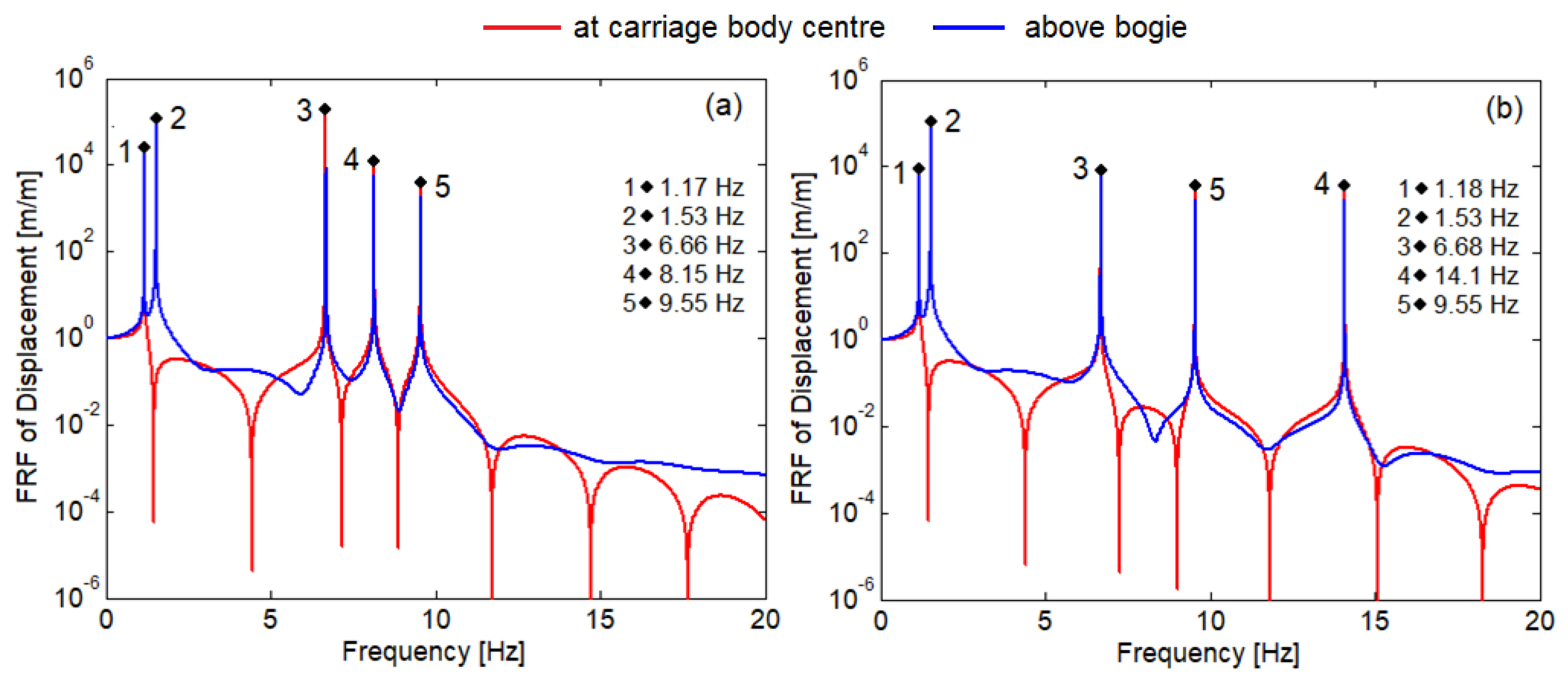
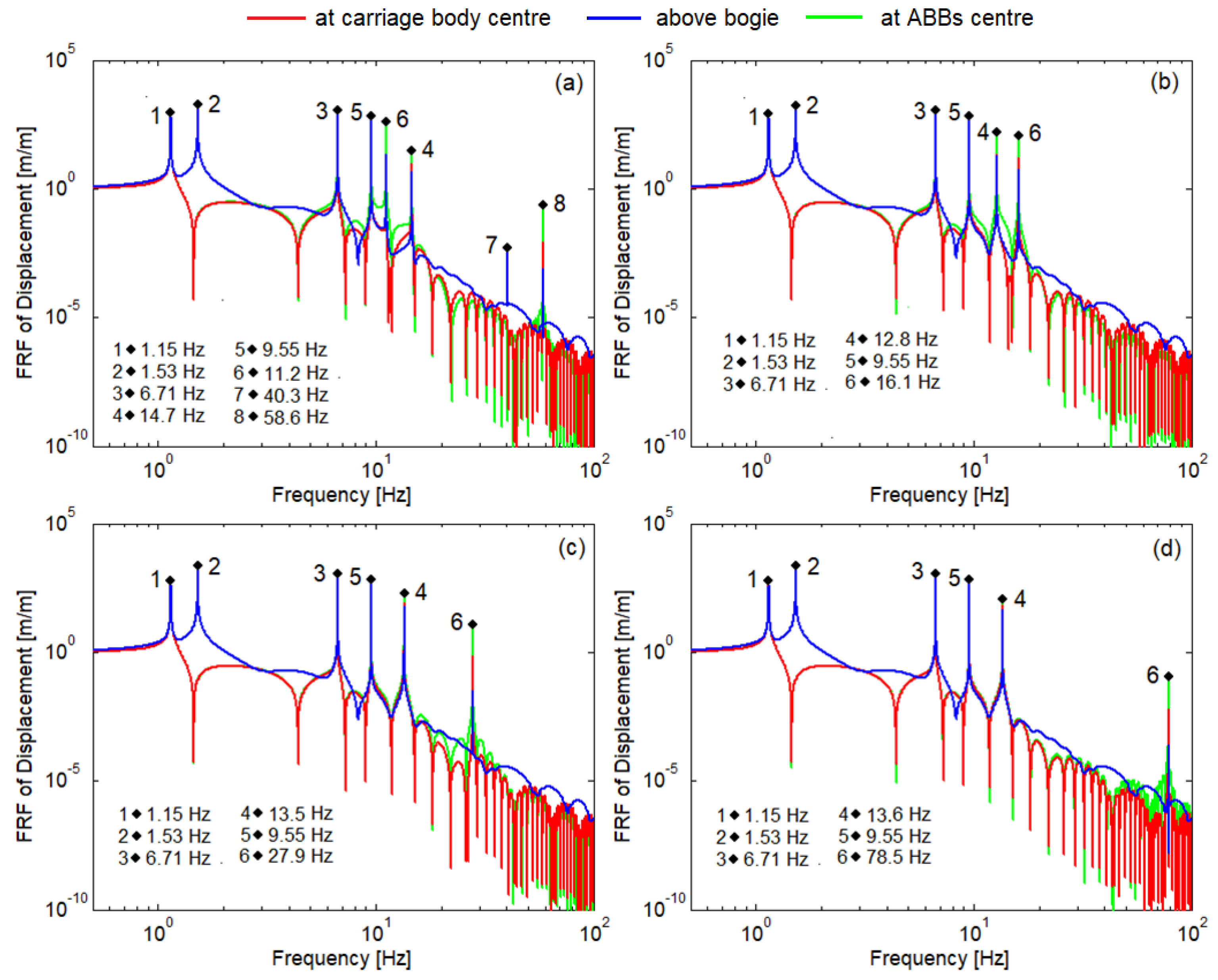
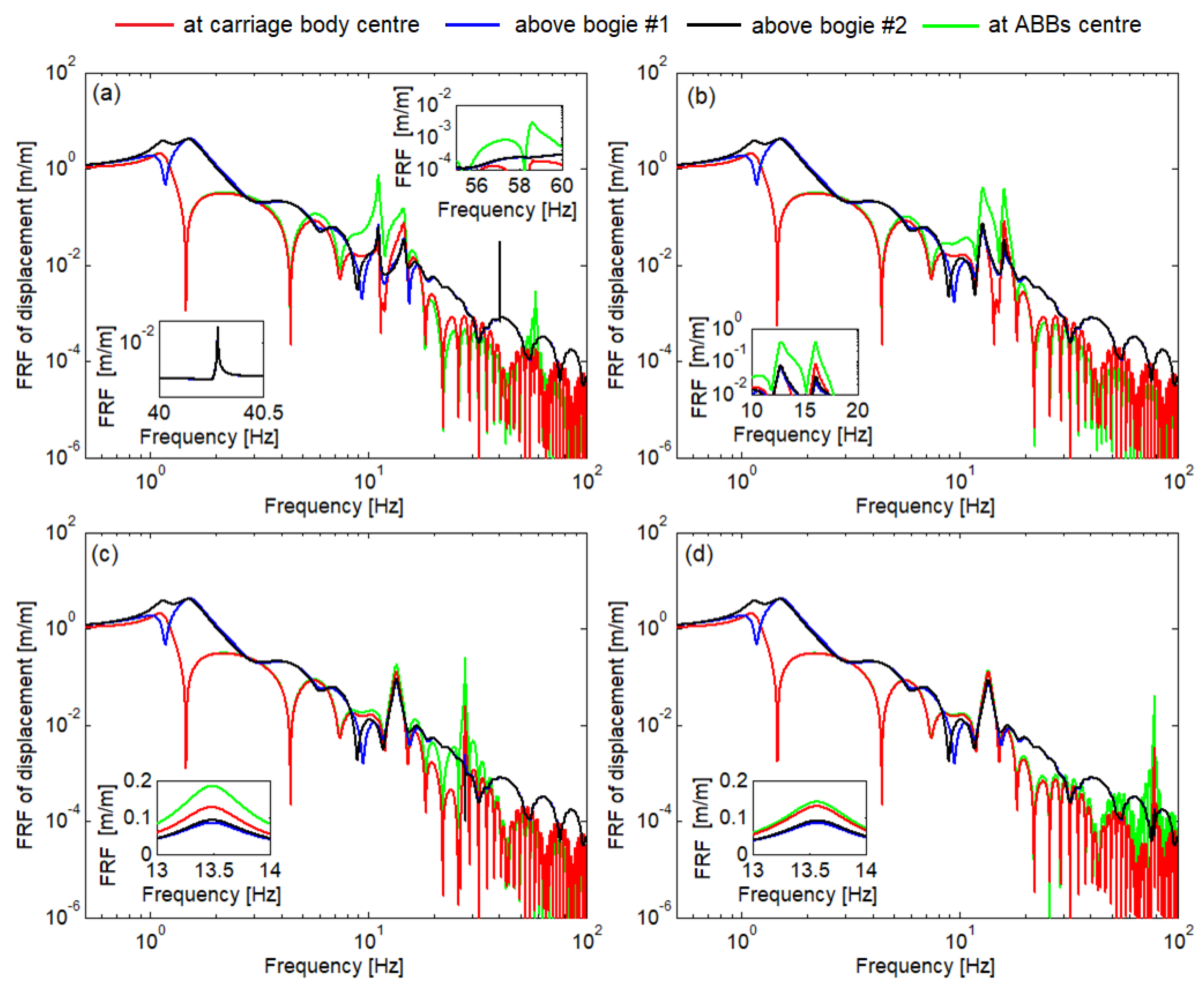
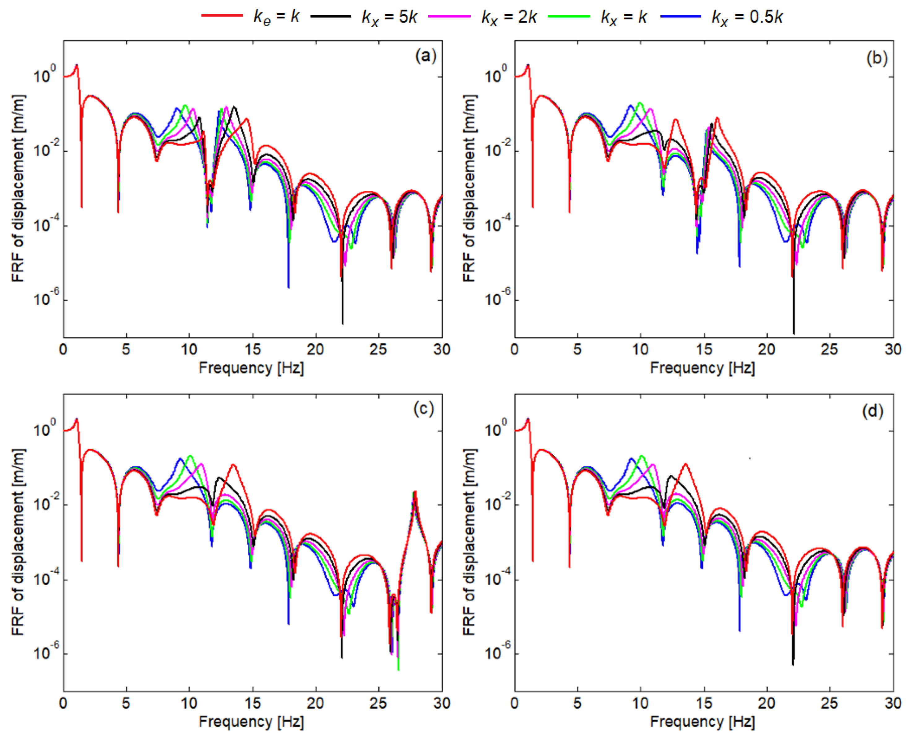
4.1. Dynamic Response of the Carriage Body with ABB

In this section, the FRFs are used to highlight the basic properties of the passenger carriage with ABBs in comparison to the two reference cases.
Table 1 presents the parameter values of the passenger carriage with ABBs and Table 2 shows the parameter values of the ABBs, both extracted from [29].
Figure 3 shows the FRF of the displacement for the reference cases (carriage body without/with ABBs) calculated at the speed of 200 km/h. Model damping is not considered to highlight the resonance frequencies. Under these conditions, the FRFs calculated above the two bogies are identical; therefore, only one of them is represented together with the FRF of the displacement in the carriage body centre.
Diagram (a) shows the resonance frequencies of the passenger carriage: the frequency of the carriage body bounce motion at 1.17 Hz, the frequency of the bogie bounce motion at 6.66 Hz, the frequency of the carriage body pitch motion at 1.53 Hz, the frequency of the bogie pitch motion at 9.55 Hz and the bending frequency of the carriage body at 8.15 Hz. The bogie pitch motion and the carriage body bending are coupled due to the longitudinal bar system, which explains the 9.55 Hz resonance in the FRF of the displacement in the carriage body centre. Here, the 9.55 Hz resonance is specific to the bogie pitch motion. In diagram (b), the effect of the ABBs on the carriage body increases the carriage body bending frequency to 14.10 Hz. The other resonance frequencies remain practically unchanged: the frequency of the carriage body bounce motion at 1.18 Hz, the frequency of the bogie bounce motion at 6.68 Hz, the frequency of the carriage body pitch motion at 1.53 Hz, and the frequency of the bogie pitch motion at 9.55 Hz.
The anti-resonance depths observed mainly in the FRF plot of the displacement in the carriage body centre come from the geometric filter effect imposed by the wheelbase of the bogie and the wheelbase of the vehicle [35,36].
Figure 4 presents the FRF of the displacement calculated in the carriage body centre and above the first bogie, and the FRF of displacement in the ABBs centre when the passenger carriage is travelling at 200 km/h. The FRFs of the displacement are calculated within the range 0.5–100 Hz, using the new model of the ABBs that considers the ABBs modes and the stiffness of the fastening. Four values are selected for the vertical stiffness of the fastening, kz = 10 MN/m, 100 MN/m, 1 GN/m and 10 GN/m, and the corresponding values of the angular stiffness kθ. Angular stiffness of the fastening is given by the equation
k θ = k z b 2 / 3 ,
where 2b is the width of the fastening; hereafter, b = 1.3d.
All the resonance frequencies of the passenger carriage highlighted in Figure 3b where the bar–spring model was used, can be identified in the four diagrams. However, small differences have to be pointed out: the frequency of the carriage body bounce motion at 1.15 Hz, the frequency of the bogie bounce motion at 6.71 Hz, the frequency of the carriage body pitch motion at 1.53 Hz and the frequency of the bogie pitch motion at 9.55 Hz.
In Figure 4a, where the vertical stiffness of the fastening is kz = 10 MN/m, the bending frequency of the ABBs at 58.6 Hz appears on both the graph of the FRF plot of the displacement in the centre of the carriage body and the FRF plot of the displacement in the centre of the ABBs. At the same time, the frequency of the pitch motion of the ABBs at 40.3 Hz also appears on the FRF plot of the displacement of the carriage body above the first bogie. The carriage body bending frequency at 14.7 Hz and the frequency ABBs of the bounce motion at 11.18 Hz are also visible. In the other three diagrams, as the vertical stiffness of the fastening increases, the bending frequency of the ABBs and the frequency of their pitch motion move out of the considered frequency range. At the same time, a progressive separation of the carriage body bending frequency from the frequency of the bounce motion of the ABBs occurs. They are located at 12.8 Hz and 16.1 Hz if kz = 100 MN/m, at 13.52 Hz and 27.9 Hz for kz = 1 GN/m, and reach 13.60 and 78.5 Hz when kz = 10 GN/m.
Figure 5 shows the FRF of the displacement calculated using the damped model in the carriage body centre and above the two bogies, and the FRF of displacement in the ABBs centre at the same speed as above. The same values of the vertical stiffness of the fastening were considered. The damping values correspond to the following damping ratio values: 0.015—the structural damping ratio of the carriage body; 0.005—the structural damping ratio of the ABBs; 0.12—the damping ratio of the secondary suspension and 0.22—the damping ratio of the primary suspension. The suspension damping ratio values correspond to the bounce motion.
Carriage body response is dominated by the two peaks situated above 10 Hz that come from the bending of the carriage body and the bounce motion of the ABBs. The most intense vibration is in the centre of the ABBs. The peak corresponding to the pitch motion of the bogie that could be observed on the FRF plot of the carriage body calculated above the bogie (Figure 4a) is now flattened due to the damping. The FRF of the carriage body displacement calculated above the bogies shows the peak of resonance due to the pitch motion of the ABBs, which is located at just above 40 Hz. At the same time, the bending mode of the ABBs appears on the FRF of the displacement from the middle of the ABBs as a maximum at 58.6 Hz.
When the vertical stiffness of the fastening is 100 MN/m, as in Figure 5b, only the two peaks of the bending of the carriage body and the bounce motion of the ABBs remain above 10 Hz. When the vertical stiffness of the fastening is 1 GN/m or 10 GN/m, as in the diagrams (c) and (d), the peak frequency corresponding to the carriage body bending stabilizes at about 13,5 Hz. Frequency response remains a little higher in the ABB centre compared to that of the carriage body, regardless of whether it is calculated in the centre or above the two bogies.
Figure 6 presents the influence of the longitudinal stiffness of the fastening on the FRF of the displacement in the carriage body centre.
The longitudinal stiffness of the fastening is proportional to the longitudinal stiffness of the bar according to the equation
k x = K k ,
where K is a proportionality factor, and K {0.5, 1, 2, 5, ∞}. For K →∞, ke = k. The calculations were carried out under similar conditions: damped model, the vehicle speed is 200 km/h and the four scenarios for the vertical stiffness of the fastening, kz = 10 MN/m, 100 MN/m, 1 GN/m and 10 GN/m.
In diagrams (a) and (b), the peak due to the bending of the carriage body and the peak of the bounce motion of the ABBs shift to lower frequencies when the equivalent longitudinal stiffness decreases because the connection between the ABBs and supports becomes more flexible. Diagrams (c) and (d) show a similar effect, with the difference that in these two cases, only the peak due to the bending of the carriage body is affected.
The last aspect considered in this section is the possibility to compensate for the reduction in the frequency of the carriage body bending mode caused by the decrease in the longitudinal stiffness of the fastening.
Figure 7 shows the FRF of the displacement in the centre of the carriage body considering five values for the bar length and kx = 5 k. Two distinct tendencies should be delimited.
First, the frequency of the bending mode of the carriage body increases when the length of the ABBs is larger because the rotation angle of the support section is larger when this section approaches the end of the carriage body.
Figure 8 presents how this angle changes along the length of the carriage body. When the bar length is 5.28 m, the rotation angle of the support section is 0.132 rad, and its value increases to 0.2016 rad, when the bar length is 8.48 m. The second tendency consists of a decrease in the frequency of the bounce motion of the ABBs when their length is longer because the bars are heavier. This tendency cannot be observed in diagrams (d) because the frequency of the bounce motion of the ABBs is higher than the upper limit of the frequency interval. On the other hand, in diagrams (b) and (c), the two tendencies are not so clear because of the interference between the bending mode of the carriage body and the bounce motion of the ABBs, and the geometric filter effect.

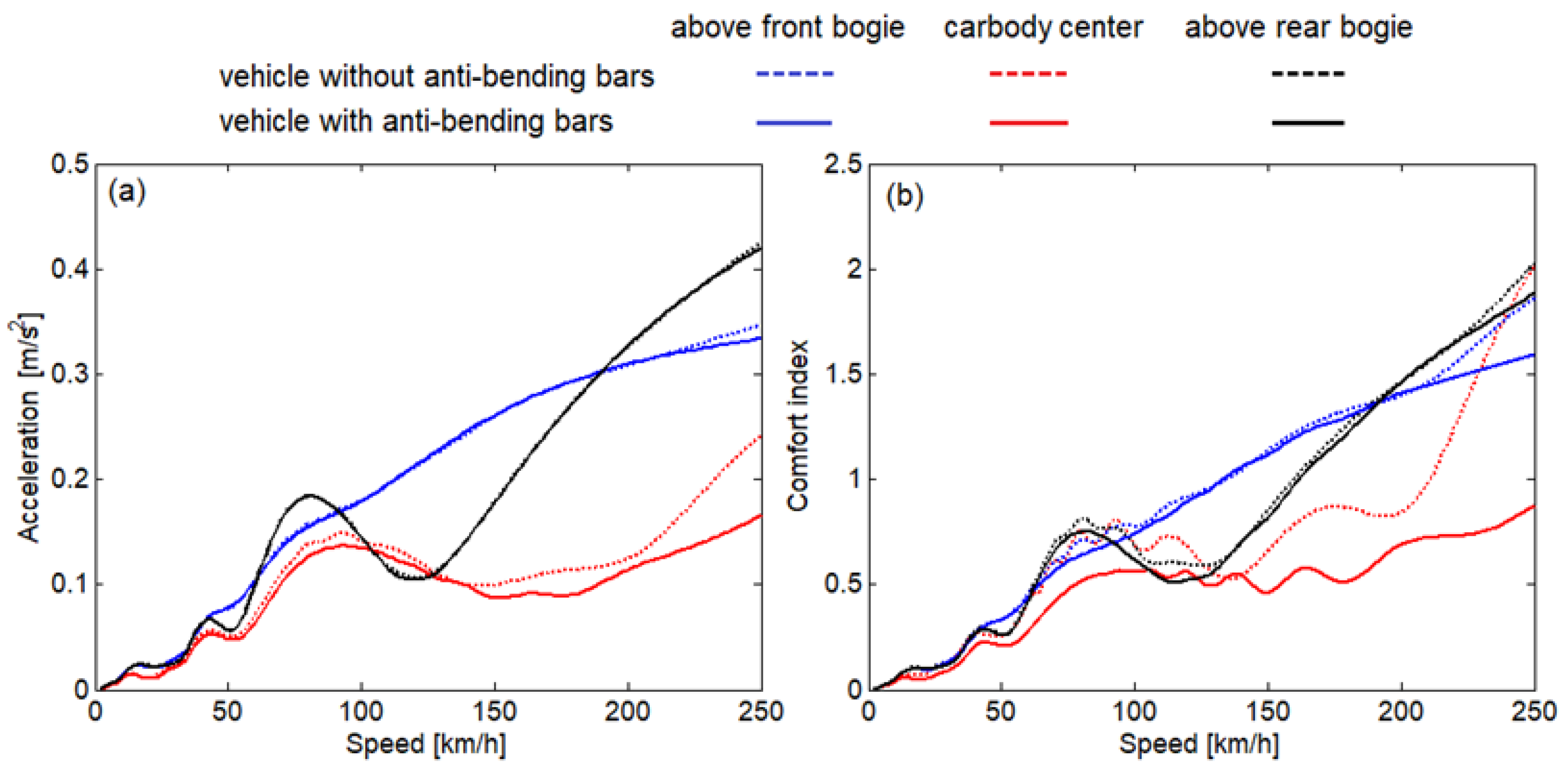
4.2. Evaluating the Running Behaviour and Comfort Index of the Passenger Carriage with ABBs

Relying on the FRFs, the vibration behaviour of the passenger carriage with ABBs when running on a track with random irregularity is evaluated in terms of the running behaviour, i.e., the acceleration and ride comfort, i.e., the comfort index [37].
Figure 9 shows the effect of the ABBs–spring model on the carriage body acceleration and the comfort index at the three critical points, in the centre of the carriage body and above the two bogies. The diagrams were constructed in the speed range 0–250 km/h.
The ABBs have a marginal effect on the running behaviour evaluated above the two bogies. The vibration behaviour in the carriage body centre is significantly improved due to the ABBs, especially from the speed of 150 km/h. The largest reductions in vibration behaviour are recorded at 176 km/h, where the acceleration decreases to 78%, and at 250 km/h, where the same parameter reaches 69% of the value calculated for the carriage body without ABBs.
The ride comfort decreases to a certain extent above the bogies due to the presence of ABBs, a more pronounced reduction being observed beyond 200 km/h especially above the front bogie. The ride comfort improves radically in the carriage body centre over almost the entire speed range investigated. However, there is a narrow speed range around 136 km/h, where the comfort index is less influenced by the ABBs. The comfort index has been sharply reduced at 178 km/h, when it reaches 59%, and at 250 km/h, when only 44% of the value obtained in the absence of ABBs is recorded.
Concluding, the effect of the ABBs influences the dynamic behaviour of the carriage body more in the centre and less above the bogie because the carriage body vibration is dominated in its centre by the bending motion, and above the bogies by the pitch motion, which is not affected by the ABBs.
Given that the effect of the ABBs practically manifests itself only in the carriage body centre, the analysis area is further narrowed, and the investigation focuses on the influence of the ABBs on vibration behaviour and comfort index in the carriage body centre using the new model of the ABBs.
Figure 10 shows the influence of the ABBs on the running behaviour and ride comfort for four values of the vertical stiffness of the fastening and ke = k. As references, the acceleration and comfort index graphs calculated for the carriage body without ABBs and the carriage body with ABBs–spring model are displayed. The introduction of the vertical stiffness of the fastening between ABBs at the vertical supports influences the results from a speed of 80 km/h. In the speed range between 80 km/h and approx. 175 km/h, the acceleration is lower due to the vertical elasticity of the fastening. At higher speeds, the acceleration calculated with the new model of the ABBs varies around that obtained with the ABBs–spring model. Similar results are obtained regarding the comfort index.
It is worth noting that the results presented in Figure 10 show that the considered values of vertical stiffness practically do not affect the functionality of ABBs, when in the longitudinal direction, fastening is perfectly rigid.
We move on to the analysis of the effect of longitudinal stiffness of the fastening of the ABBs to the supports. The values of the proportionality factor from Section 4.1 are considered, namely K {0.5, 1, 2, 5}.
Figure 11 shows the acceleration and comfort index in the carriage body centre for the four values of the longitudinal stiffness of the fastening resulting from the values of the proportionality factor K, considering for each case, the values of the vertical stiffness of the fastening kz = 10 MN/m, 100 MN/m, 1 GN/m and 10 GN/m.
The acceleration and comfort index in the carriage body centre for the two reference cases, the carriage body without ABBs and the carriage body with ABBs–spring model, are also shown.
Examining the two sets of diagrams, it follows that as the longitudinal stiffness of the fastening decreases, both the acceleration and the comfort index increase, which affects the effectiveness of the ABBs. In addition, a reduction in the differences between the curves of the acceleration and the comfort index for different values of the vertical stiffness of the fastening is observed when the longitudinal stiffness is lower. It follows that the reduction in the effectiveness of the ABBs in the case of their more elastic fastening to the supports by increasing the vertical stiffness kz cannot be counteracted.
In Figure 12, the longitudinal stiffness of the fastening has the lowest value considered in this parametric study and corresponds to the proportionality factor K = 0.5. The length of the ABBs is 5.28 m in diagrams (a) and (a’), 6.88 m in diagrams (b) and (b’) and 8.48 m in diagrams (c) and (c’), respectively; these are considered to evaluate the effect of increasing the length of the ABBs on their ability to reduce the vibration behaviour of the carriage body and improve ride comfort.
By using longer ABBs, performance improvements are achieved in the medium and high-speed range. The best results are obtained if the vertical stiffness of the fastening is higher (kz = 1 GN/m or 10 GN/m), according to diagrams (c) and (c’).

5. Conclusions

In this paper, a new model of the passenger carriage with ABBs is proposed to point out the influence of the fastening parameters and vibration modes of the ABBs on the running behaviour and ride comfort.
The new model of the passenger carriage with ABBs includes the carriage body, the ABBs were each considered as a free-free Euler–Bernoulli beam, the fastening between the ABBs and the vertical supports modelled using three elastic elements working in the vertical plane, the secondary suspension represented by two Kelvin–Voigt systems for vertical and longitudinal displacement, the two bogie frame assimilated by two degrees of freedom rigid objects and the primary suspension taken as a vertical Kelvin–Voigt system. The track is considered rigid with harmonic irregularity for the derivation of FRFs, and with random irregularity to evaluate the running behaviour and ride comfort. The application of the modal analysis method allows us to include the most important vibration modes of the carriage body and ABBs, namely the bounce motion, pitch motion and the first bending mode in the new model of the passenger carriage with ABBs.
The main conclusions drawn are as follows:
(a)
The parametric study of the FRF of the carriage body shows that the vibration behaviour of the carriage body is a little influenced by the vertical stiffness of the fastening;
(b)
The parametric study of the FRF of the ABBs shows that the resonance peaks move along the frequency axis as the fastening between the ABBs and the vertical supports is more rigid in the vertical direction;
(c)
The running behaviour reflected by the acceleration and the ride comfort quantified by the comfort index are not significantly influenced by the vertical stiffness of the fastening, if the fastening is perfectly rigid in the longitudinal direction;
(d)
When the fastening becomes elastic in the longitudinal direction, then both the running behaviour and ride comfort are affected;
(e)
To compensate the depreciation in terms of running behaviour and ride comfort caused by the above situation, longer ABBs with stiffer fastening in the vertical direction should be used.
From a practical viewpoint, the design of the fastening between the ABBs and the vertical supports is a difficult task, since the longitudinal stiffness is the critical parameter and must be as high as possible.
Further research should address the issues raised by the implementation of the ABBs, such as the evaluation of the fatigue risk in the system components.

Author Contributions

Conceptualization, T.M. and I.-I.A.; methodology, T.M. and M.D.; software, T.M. and I.-I.A.; validation, T.M., M.D. and I.-I.A.; formal analysis, T.M. and M.D.; investigation, I.-I.A., T.M. and M.D.; resources, M.D. and I.-I.A.; data curation, I.-I.A.; writing—original draft preparation, T.M. and I.-I.A.; writing—review and editing, M.D.; visualization, I.-I.A.; supervision, T.M.; project administration, T.M. All authors have read and agreed to the published version of the manuscript.

Funding

This research was funded by a grant from the National Program for Research of the National Association of Technical Universities—GNAC ARUT 2023, contract no. 154/04.12.2023.

Institutional Review Board Statement

Not applicable.

Informed Consent Statement

Not applicable.

Data Availability Statement

Data are contained within the article.

Conflicts of Interest

The authors declare no conflicts of interest.

References

  1. EN 12299; Railway Applications. Ride Comfort for Passengers. Measurement and Evaluation. European Committee for Standardization: Brussels, Belgium, 1999.
  2. Testing and Approval of Railway Vehicles from the Point of View of Their Dynamic Behaviour-Safety-Track Fatigue-Running Behaviour, 4th ed.; UIC 518 Leaflet: Paris, France, 2009.
  3. Zhang, C.; Kordestani, H.; Shadabfar, M. A combined review of vibration control strategies for high-speed trains and railway infrastructures: Challenges and solutions. J. Low Freq. Noise Vib. Act. Control 2023, 42, 272–291. [Google Scholar] [CrossRef]
  4. Tomioka, T.; Takigami, T.; Suzuki, Y. Numerical analysis of three-dimensional flexural vibration of railway vehicle car body. Veh. Syst. Dyn. 2006, 44 (Suppl. S1), 272–285. [Google Scholar] [CrossRef]
  5. Hui, C.; Weihua, Z.; Bingring, M. Vertical vibration analysis of the flexible carbody of high-speed train. Int. J. Veh. Struct. Syst. 2015, 7, 55–60. [Google Scholar] [CrossRef]
  6. Palomares, E.; Morales, A.L.; Nieto, A.J.; Chicharro, J.M.; Pintado, P. Comfort improvement in railway vehicles via optimal control of adaptive pneumatic suspensions. Veh. Syst. Dyn. 2022, 60, 1702–1721. [Google Scholar] [CrossRef]
  7. Lewis, T.D.; Jiang, J.Z.; Neild, S.A.; Gong, C.; Iwnicki, S.D. Using an inerter-based suspension to improve both passenger comfort and track wear in railway vehicles. Veh. Syst. Dyn. 2020, 58, 472–493. [Google Scholar] [CrossRef]
  8. Sugahara, Y.; Kojima, T. Suppression of vertical vibration in railway vehicle carbodies through control of damping force in primary suspension: Presentation of results from running tests with meter-gauge car on a secondary line. WIT Trans. Built Environ. 2018, 181, 329–337. [Google Scholar]
  9. Sugahara, Y.; Kazato, A.; Koganei, R.; Sampei, M.; Nakaura, S. Suppression of vertical bending and rigid-body-mode vibration in railway vehicle car body by primary and secondary suspension control: Results of simulations and running tests using Shinkansen vehicle. Proc. Inst. Mech. Eng. J. Rail Rapid Transit 2009, 223, 517–531. [Google Scholar] [CrossRef]
  10. Chen, J.; Wu, Y.; Zhang, L.; He, X.; Dong, S. Dynamic optimization design of the suspension parameters of car body mounted equipment via analytical target cascading. J. Mech. Sci. Technol. 2020, 34, 1957–1969. [Google Scholar] [CrossRef]
  11. Dumitriu, M. Study on improving the ride comfort in railway vehicles using anti-bending dampers. Appl. Mech. Mater. 2018, 880, 207–212. [Google Scholar] [CrossRef]
  12. Gong, D.; Wang, K.; Duan, Y.; Zhou, J. Car body floor vibration of high-speed railway vehicles and its reduction. J. Low Freq. Noise Vibr. Act. Control 2020, 39, 925–938. [Google Scholar] [CrossRef]
  13. Graa, M. Modeling and control for vertical rail vehicle dynamic vibration with comfort evaluation. Int. J. Math. Model. Methods Appl. Sci. 2017, 11, 240–245. [Google Scholar]
  14. Gong, D.; Zhou, J.; Sun, W. Passive control of railway vehicle car body flexural vibration by means of under frame dampers. J. Mech. Sci. Technol. 2017, 31, 555–564. [Google Scholar] [CrossRef]
  15. Huang, C.; Zeng, J.; Luo, G.; Shi, H. Numerical and experimental studies on the car body flexible vibration reduction due to the effect of car body-mounted equipment. Proc. Inst. Mech. Eng. J. Rail Rapid Transit 2016, 232, 103–120. [Google Scholar] [CrossRef]
  16. Isacchi, G.; Corsi, M.; Ripamonti, F. Ride comfort assessment of high-speed rail vehicles: Influence of yaw dampers installation angle. Vibroengineering Procedia 2023, 50, 98–104. [Google Scholar] [CrossRef]
  17. Johnssons, A.; Berbyuk, V.; Enelund, M. Pareto optimisation of railway bogie suspension damping to enhance safety and comfort. Veh. Syst. Dyn. 2012, 50, 1379–1407. [Google Scholar] [CrossRef]
  18. Nakajima, D.; Aida, K.I.; Akiyama, Y.; Tkigami, T.; Tomioka, T.; Nishiyama, Y.; Tanaka, T.; Miyamoto, T. Development of a new mounting structure of yaw damper to reduce railway carbody vibration. Trans. JSME 2017, 83, 17–00078. (In Japanese) [Google Scholar]
  19. Shi, H.L.; Luo, R.; Wu, P.B.; Zeng, J.; Guo, J.Y. Application of DVA theory in vibration reduction of carriage body with suspended equipment for high-speed EMU. Sci. China Technol. Sci. 2014, 57, 1425–1438. [Google Scholar] [CrossRef]
  20. Sharma, S.K.; Sharma, R.C.; Lee, J.; Jang, H.L. Numerical and experimental analysis of DVA on the flexible-rigid rail vehicle carriage body resonant vibration. Sensors 2022, 22, 1922. [Google Scholar] [CrossRef] [PubMed]
  21. Nitish; Singh, A.K. Active control of railway vehicle suspension using PID controller with pole placement technique. Mater. Today Proc. 2023, 80, 278–284. [Google Scholar] [CrossRef]
  22. Kozek, M.; Benatzky, C.; Schirrer, A.; Stribersky, A. Vibration Damping of a Flexible Car Body Structure Using Piezo-Stack Actuators. In Proceedings of the 17th World Congress The International Federation of Automatic Control, Seoul, Republic of Korea, 6–11 July 2008; pp. 8284–8299. [Google Scholar]
  23. Kamada, T.; Hiraizumi, T.; Nagai, M. Active vibration suppression of lightweight railway vehicle body by combined use of piezoelectric actuators and linear actuators. Veh. Syst. Dyn. 2010, 48, 73–87. [Google Scholar] [CrossRef]
  24. Takigami, T.; Tomioka, T. Bending vibration suppression of railway vehicle carbody with piezoelectric elements (Experimental results of excitation tests with a commuter car). J. Mech. Syst. Transp. Logist. 2008, 1, 111–121. [Google Scholar] [CrossRef]
  25. Zhou, J.; Goodall, R.; Ren, L.; Zhang, H. Influences of car body vertical flexibility on ride quality of passenger railway vehicles. Proc. Inst. Mech. Eng. J. Rail Rapid Transit 2009, 223, 461–471. [Google Scholar] [CrossRef]
  26. Cheli, F.; Corradi, R. On rail vehicle vibrations induced by track unevenness: Analysis of the excitation mechanism. J. Sound Vib. 2011, 330, 3744–3765. [Google Scholar] [CrossRef]
  27. You, T.; Zhou, J.; Thompson, D.J.; Gong, D.; Chen, J.; Sun, Y. Vibration reduction of a high-speed train floor using multiple dynamic vibration absorbers. Veh. Syst. Dyn. 2022, 60, 2919–2940. [Google Scholar] [CrossRef]
  28. Gong, D.; Zhao, K.; Liu, G.; Wang, Z.; You, T.; Zhou, J. Modal vibration decomposition method and its application on multi-mode vibration control of high-speed railway car bodies. J. Frankl. Inst. 2022, 359, 4699–4726. [Google Scholar] [CrossRef]
  29. Dumitriu, M. A new passive approach to reducing the carbody vertical bending vibration of railway vehicles. Veh. Syst. Dyn. 2017, 55, 1787–1806. [Google Scholar] [CrossRef]
  30. Fu, B.; Bruni, S. An examination of alternative schemes for active and semi-active control of vertical car-body vibration to improve ride comfort. Proc. Inst. Mech. Eng. J. Rail Rapid Transit 2022, 236, 386–405. [Google Scholar] [CrossRef]
  31. Fu, B.; Liu, B.; Di Gialleonardo, E.; Bruni, S. Semi-active control of primary suspensions to improve ride quality in a high-speed railway vehicle. Veh. Syst. Dyn. 2023, 61, 2664–2688. [Google Scholar] [CrossRef]
  32. Dumitriu, M.; Mazilu, T.; Apostol, I.I. Scale Models to Verify the Effectiveness of the Methods to Reducing the Vertical Bending Vibration of the Railway Vehicles Carbody: Applications and Design Elements. Appl. Sci. 2023, 13, 2368. [Google Scholar] [CrossRef]
  33. Mazilu, T.; Dumitriu, M.; Sorohan, Ș.; Gheți, M.A.; Apostol, I.I. Testing the Effectiveness of the Anti-Bending Bar System to Reduce the Vertical Bending Vibrations of the Railway Vehicle Carbody Using an Experimental Scale Demonstrator. Appl. Sci. 2024, 14, 4687. [Google Scholar] [CrossRef]
  34. Apostol, I.I.; Mazilu, T.; Dumitriu, M. Study on Dynamic Response of the Carbody–Anti-Bending Bar System. Technologies 2025, 13, 31. [Google Scholar] [CrossRef]
  35. Gong, D.; Gu, Y.J.; Song, Y.J.; Zhou, J. Study on geometry filtering phenomenon and flexible car body resonant vibration of articulated trains. Adv. Mater. Res. 2013, 787, 542–547. [Google Scholar] [CrossRef]
  36. Zhou, J.; Wenjing, S. Analysis on geometric filtering phenomenon and flexible car body resonant vibration of railway vehicles. J. Tongji Univ. 2009, 37, 1653–1657. [Google Scholar]
  37. Dumitriu, M.; Apostol, I.I. The Effect of the Traction Rod on the Vertical Vibration Behavior of the Railway Vehicle Carbody. Vehicles 2023, 5, 1482–1504. [Google Scholar] [CrossRef]
Figure 1. Principle of the carriage body with ABBs: 1. carriage body; 2. ABB; 3. vertical support.
Technologies 13 00073 g001
Figure 2. Mechanical model of the passenger carriage with an ABB system.
Technologies 13 00073 g002
Figure 3. FRF of the displacement in the carriage body centre and above the first bogie: (a) carriage body without ABBs; (b) carriage body with ABBs–spring model.
Technologies 13 00073 g003
Figure 4. FRFs of the displacement (undamped model): (a) kz = 10 MN/m; (b) kz = 100 MN/m; (c) kz = 1 GN/m; (d) kz = 10 GN/m.
Technologies 13 00073 g004
Figure 5. FRFs of the displacement (damped model): (a) kz = 10 MN/m; (b) kz = 100 MN/m; (c) kz = 1 GN/m; (d) kz = 10 GN/m.
Technologies 13 00073 g005
Figure 6. FRF of the displacement in the carriage body centre–influence of the longitudinal stiffness of the fastening: (a) kz = 10 MN/m; (b) kz = 100 MN/m; (c) kz = 1 GN/m; (d) kz = 10 GN/m.
Technologies 13 00073 g006
Figure 7. FRF of the displacement in the carriage body centre–influence of the bar length: (a) kz = 10 MN/m; (b) kz = 100 MN/m; (c) kz = 1 GN/m; (d) kz = 10 GN/m.
Technologies 13 00073 g007
Figure 8. Rotation angle of the support section.
Technologies 13 00073 g008
Figure 9. Effect of the ABBs–spring model on the running behaviour and ride comfort: (a) running behaviour; (b) ride comfort.
Technologies 13 00073 g009
Figure 10. Influence of the vertical stiffness of the fastening on the running behaviour and ride comfort (ke = k): (a) running behaviour; (b) ride comfort.
Technologies 13 00073 g010
Figure 11. Influence of the vertical stiffness of the fastening on the running behaviour and ride comfort (ke = k): (ad) running behaviour; (a’d’) ride comfort; (a,a’) K = 5; (b,b’) K = 2; (c,c’) K = 1; (d,d’) K = 0.5.
Technologies 13 00073 g011
Figure 12. Influence of the ABBs length on the running behaviour and ride comfort (K = 0.5): (ac) running behaviour; (a’c’) ride comfort; (a,a’) l = 5.28 m; (b,b’) l = 6.88 m; (c,c’) l = 8.48 m.
Technologies 13 00073 g012
Table 1. Parameters of the vehicle with ABBs.
mc = 34,000 kglc2 = 3.7 m
mb = 3200 kg2kzc = 1.2 MN/m
Jc = 1,963,840 kg m22kxc = 4 MN/m
Jb = 2048 kg m22czc = 34.28 kNs/m
EcIc = 3.158 × 10⁹ Nm22cxc = 50 kNs/m
lc = 26.4 m4kzb = 4.4 MN/m
2ac = 19 m4czb = 52.21 kNs/m
2ab = 2.56 mmmc = 35,224 kg
hc = 1.3 mkmc = 88.998 MN/m
hb = 0.2 mcmc = 53.117 kNs/m
lc1 = 22.7 mh = 1.2 m;
Table 2. Parameters of the ABBs.
m = 941 kgk = 902.76 MN/m
ρ = 178.18 kg/mmm = 975 kg
E = 210 GPakm = 30.33 MN/m
l = 5.28 mcm = 860 Ns/m
d = 0.17 ml1 = 15.84 m
I = 4.0998 × 10⁻⁵ m4l2 = 10.56 m
Disclaimer/Publisher’s Note: The statements, opinions and data contained in all publications are solely those of the individual author(s) and contributor(s) and not of MDPI and/or the editor(s). MDPI and/or the editor(s) disclaim responsibility for any injury to people or property resulting from any ideas, methods, instructions or products referred to in the content.

