

High-Gain Miniaturized Multi-Band MIMO SSPP LWA for Vehicular Communications

 ,
,  , ,
, ,  ,
,
Abstract
1. Introduction
1.1. Current Developments and Novel Contributions of the Study
1.2. Paper’s Contributions
2. Design Configuration
2.1. The Configurations of SSPP and Their Defining Principles
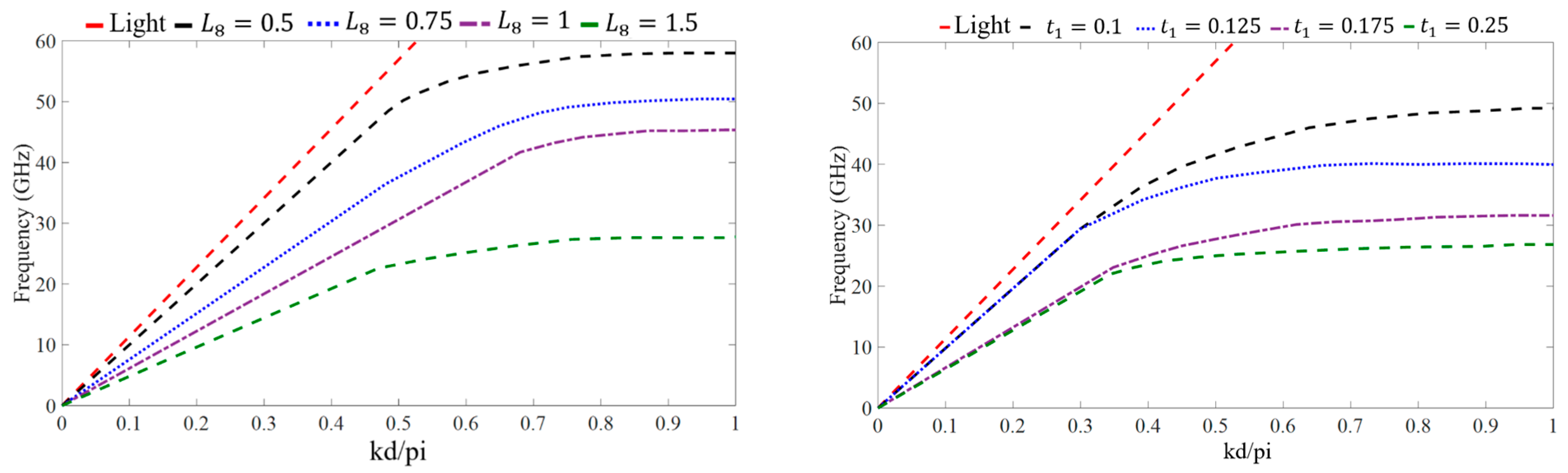
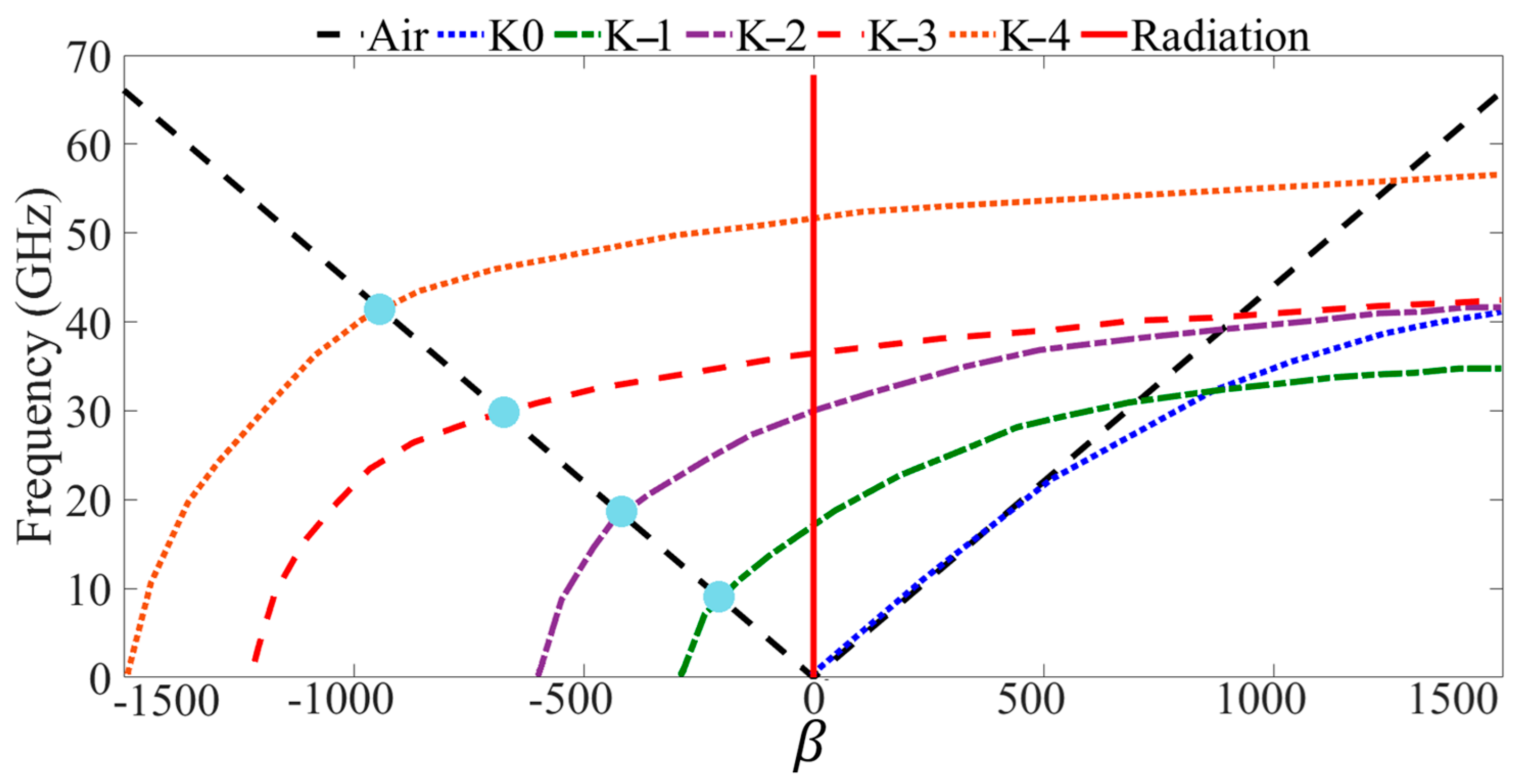
2.2. Leaky Wave Designs, Their Fundamental Concepts, and Integration with SSPPs Section
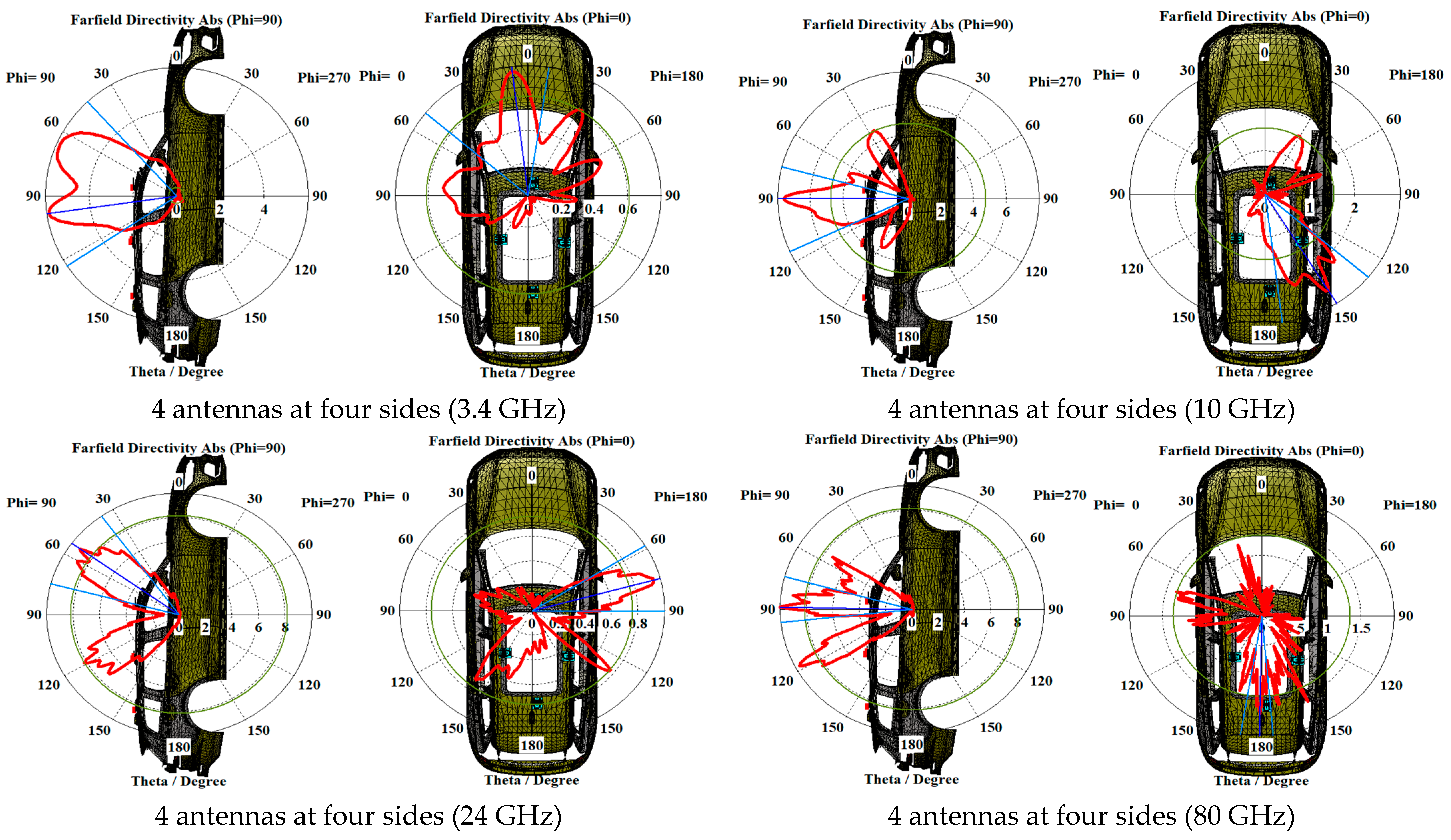
3. Evaluation of the Antenna’s Performance in a Vehicular Environment
SAR Definition and Analysis
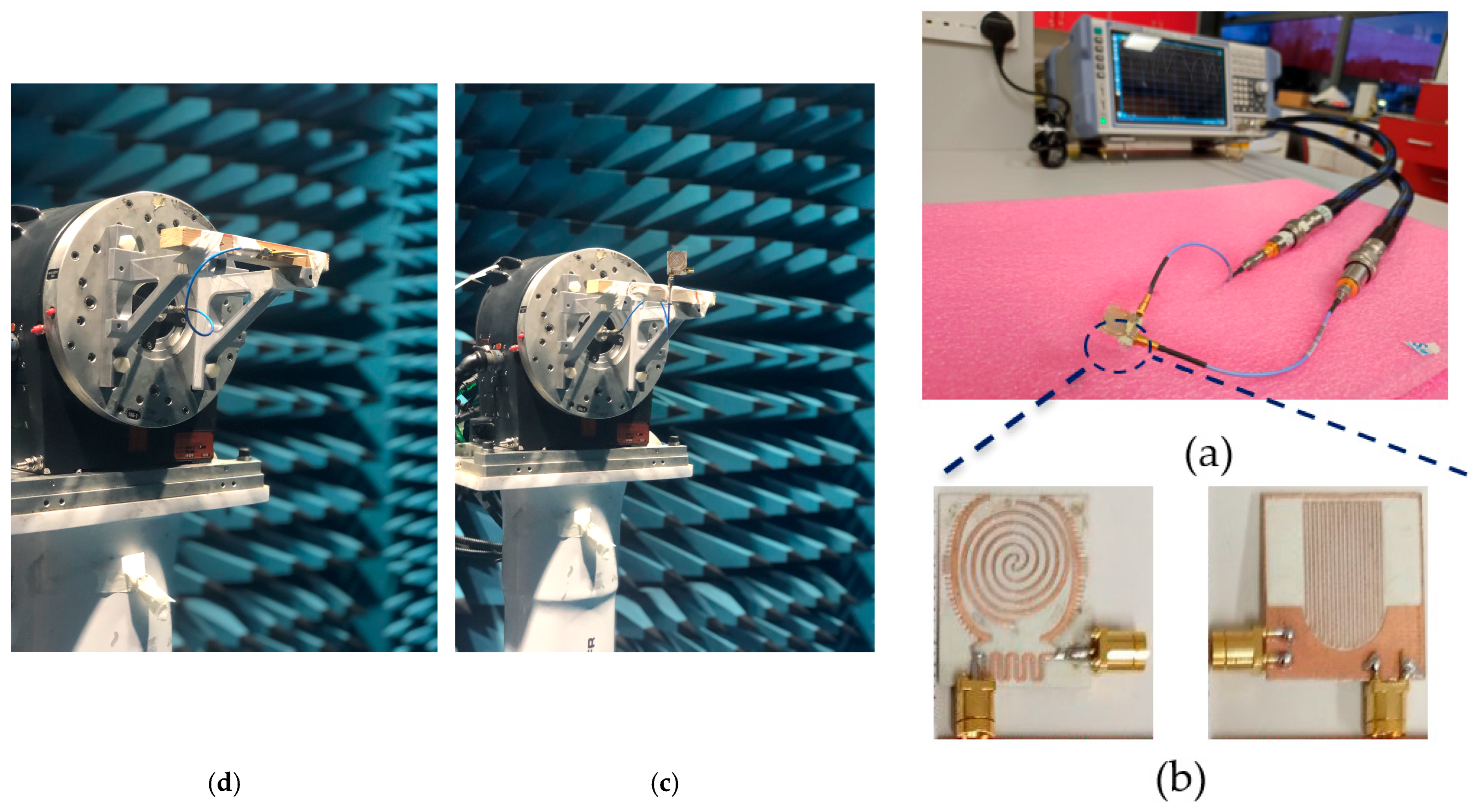
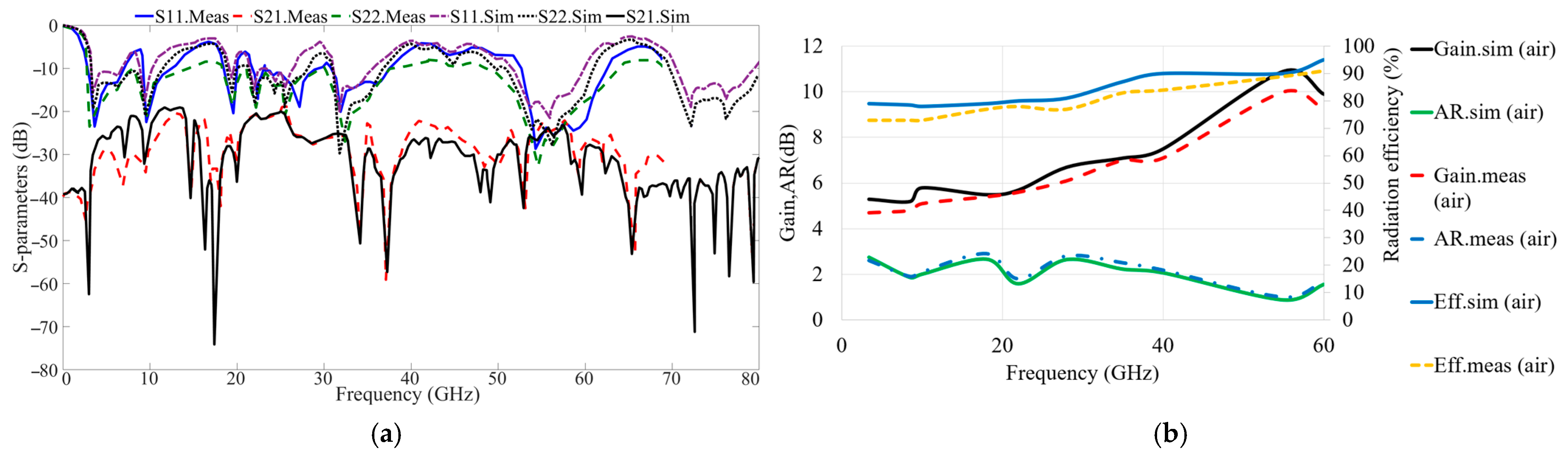
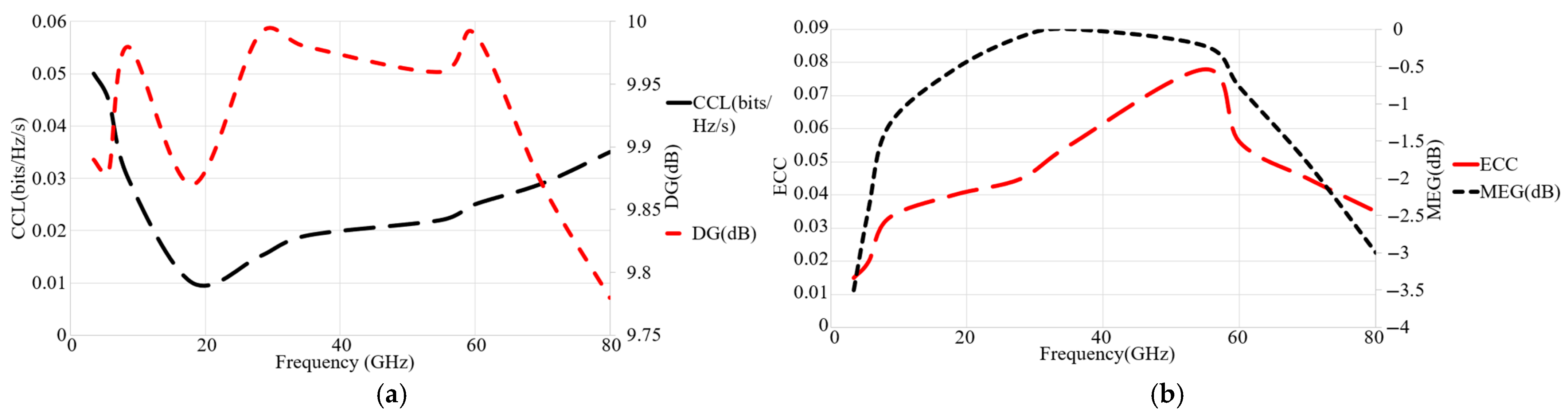
4. Experimental Confirmation and Analysis of Findings
5. Conclusions
Author Contributions
Funding
Institutional Review Board Statement
Informed Consent Statement
Data Availability Statement
Acknowledgments
Conflicts of Interest
References
- Mahmood, D.A.; Reja, A.H.; Mahmood, A.M. Enhancement of information propagation on the highway in VANET based on Multiple Vehicle Class. In Proceedings of the International Conference on ICT Convergence 2022, Jeju Island, Republic of Korea, 19–21 October 2022; pp. 1419–1424. [Google Scholar] [CrossRef]
- Ström, E.G.; Ekiz, L.; Abbas, T.; He, R.; Ambroziak, S.J.; Shivaldova, V.; Nuckelt, J. Vehicular communication environments. In Cooperative Radio Communications for Green Smart Environments; River Publishers: Roma, Italy, 2016; pp. 121–150. [Google Scholar] [CrossRef]
- Ghafoor, K.Z.; Kong, L.; Zeadally, S.; Sadiq, A.S.; Epiphaniou, G.; Hammoudeh, M.; Bashir, A.K.; Mumtaz, S. Millimeter-wave Communication for Internet of Vehicles: Status, Challenges and Perspectives. IEEE Internet Things J. 2020, 7, 8525–8546. [Google Scholar] [CrossRef]
- Pirayesh, H.; Zeng, H. Jamming Attacks and Anti-Jamming Strategies in Wireless Networks: A Comprehensive Survey. IEEE Commun. Surv. Tutor. 2022, 24, 767–809. [Google Scholar] [CrossRef]
- Giordani, M.; Zanella, A.; Zorzi, M. Millimeter wave communication in vehicular networks: Challenges and opportunities. In Proceedings of the 2017 6th International Conference on Modern Circuits and Systems Technologies (MOCAST), Thessaloniki, Greece, 4–6 May 2017; pp. 1–6. [Google Scholar]
- Na, W.; Lakew, S.; Lee, J.; Cho, S. Congestion control vs. link failure: TCP behavior in mmWave connected vehicular networks. Future Gener. Comput. Syst. 2019, 101, 1213–1222. [Google Scholar] [CrossRef]
- Pons, M.; Valenzuela, E.; Rodríguez, B.; Nolazco-Flores, J.A.; Del-Valle-Soto, C. Utilization of 5G Technologies in IoT Applications: Current Limitations by Interference and Network Optimization Difficulties—A Review. Sensors 2023, 23, 3876. [Google Scholar] [CrossRef]
- Saleh, S.; Saeidi, T.; Timmons, N.; Razzaz, F. A comprehensive review of recent methods for compactness and performance enhancement in 5G and 6G wearable antennas. Alex. Eng. J. 2024, 95, 132–163. [Google Scholar] [CrossRef]
- Nasr, A.M.H.; Sarabandi, K. A Low-Cost Millimeter-Wave 5G V2X Multi-Beam Dual-Polarized Windshield Antenna. IEEE Open J. Antennas Propag. 2022, 3, 1313–1323. [Google Scholar] [CrossRef]
- Ballesteros, C.; Montero, L.; Ramírez, G.A.; Jofre-Roca, L. Multi-antenna 3D pattern design for millimeter-wave vehicular communications. Veh. Commun. 2022, 35, 100473. [Google Scholar] [CrossRef]
- Dzagbletey, P.A.; Shim, J.; Chung, J. Quarter-Wave Balun Fed Vivaldi Antenna Pair for V2X Communication Measurement. IEEE Trans. Antennas Propag. 2019, 67, 1957–1962. [Google Scholar] [CrossRef]
- Bonato, M.; Tognola, G.; Benini, M.; Gallucci, S.; Chiaramello, E.; Fiocchi, S.; Parazzini, M. Assessment of SAR in Road-Users from 5G-V2X Vehicular Connectivity Based on Computational Simulations. Sensors 2022, 22, 6564. [Google Scholar] [CrossRef] [PubMed]
- Kim, W. Experimental Demonstration of MmWave Vehicle-to-Vehicle Communications Using IEEE 802.11ad. Sensors 2019, 19, 2057. [Google Scholar] [CrossRef]
- Ikram, M.; Sultan, K.S.; Abbosh, A.M.; Nguyen-Trong, N. Sub-6 GHz and mm-Wave 5G Vehicle-to-Everything (5G-V2X) MIMO Antenna Array. IEEE Access 2022, 10, 49688–49695. [Google Scholar] [CrossRef]
- Im, C.; Lim, T.H.; Jang, D.; Kong, N.K.; Choo, H. Design of a printed 5G monopole antenna on vehicle window glass using parasitic elements and a lattice-structure reflector for gain enhancement. Appl. Sci. 2021, 11, 9953. [Google Scholar] [CrossRef]
- Sun, Y.X.; Leung, K.W.; Lu, K. Compact Dual Microwave/Millimeter-Wave Planar Shared-Aperture Antenna for Vehicle-to-Vehicle/5G Communications. IEEE Trans. Veh. Technol. 2021, 70, 5071–5076. [Google Scholar] [CrossRef]
- Ding, X.H.; Yang, W.W.; Tang, H.; Guo, L.; Chen, J.X. A Dual-Band Shared-Aperture Antenna for Microwave and Millimeter-Wave Applications in 5G Wireless Communication. IEEE Trans. Antennas Propag. 2022, 70, 12299–12304. [Google Scholar] [CrossRef]
- Wang, C.; Cao, W.; Ma, W.; Tong, Y.; Zhu, Y. A Sigle-Layer Dual-Band Shared-Aperture Antenna With High Gain and Sidelobe Suppression Based on High-Order Mode for Vehicular Communications. IEEE Trans. Veh. Technol. 2023, 73, 473–481. [Google Scholar] [CrossRef]
- Xu, S.-D.; Guan, D.-F.; Zhang, Q.; You, P.; Ge, S.; Hou, X.-X.; Yang, Z.-B.; Yong, S.-W. A Wide-Angle Narrowband Leaky-Wave Antenna Based on Substrate Integrated Waveguide-Spoof Surface Plasmon Polariton Structure. IEEE Antennas Wirel. Propag. Lett. 2019, 18, 1386–1389. [Google Scholar] [CrossRef]
- Ren, B.; Li, W.; Qin, Z.; Wang, Y.; Zhang, L.; Zhang, B. Leaky Wave Antenna Based on Periodically Truncated SSPP Waveguide. Plasmonics 2020, 15, 551–558. [Google Scholar] [CrossRef]
- Bryant, B.; Won, H.; Hong, Y.K.; Lee, W.; Choi, M. Design of Triple-Band (DSRC, 5G, 6G) Antenna for Autonomous Vehicle Telematics. Electronics 2022, 11, 2523. [Google Scholar] [CrossRef]
- Rao, M.V.; Madhav, B.T.P.; Krishna, J.; Devi, Y.U.; Anilkumar, T.; Nadh, B.P. CSRR-loaded T-shaped MIMO antenna for 5G cellular networks and vehicular communications. Int. J. RF Microw. Comput.-Aided Eng. 2019, 29, e21799. [Google Scholar] [CrossRef]
- Jang, D.; Kong, N.K.; Choo, H. Design of an On-Glass 5G Monopole Antenna for a Vehicle Window Glass. IEEE Access 2021, 9, 152749–152755. [Google Scholar] [CrossRef]
- Im, C.; Lim, T.H.; Choo, H. Design of a mmWave Antenna Printed on a Thick Vehicle-Glass Substrate Using a Linearly Arrayed Patch Director and a Grid-Slotted Patch Reflector for High-Gain Characteristics. Sensors 2022, 22, 6187. [Google Scholar] [CrossRef] [PubMed]
- Youn, S.; Jang, D.; Kong, N.K.; Choo, H. Design of a Printed 5G Monopole Antenna with Periodic Patch Director on the Laminated Window Glass. IEEE Antennas Wirel. Propag. Lett. 2022, 21, 297–301. [Google Scholar] [CrossRef]
- Tan, H.; Zheng, W.; Vijayakumar, P. Secure and Efficient Authenticated Key Management Scheme for UAV-Assisted Infrastructure-Less IoVs. IEEE Trans. Intell. Transp. Syst. 2023, 24, 6389–6400. [Google Scholar] [CrossRef]
- Liu, P.; He, Q.; Chen, Y.; Jiang, S.; Zhao, B.; Wang, X. A Lightweight Authentication and Privacy-Preserving Aggregation for Blockchain-Enabled Federated Learning in VANETs. IEEE Trans. Consum. Electron. 2024; Early Access. [Google Scholar]
- Pan, X.; Jin, Y.; Li, F. An efficient heterogeneous authenticated key agreement scheme for unmanned aerial vehicles. J. Syst. Arch. 2023, 136, 102821. [Google Scholar] [CrossRef]
- Nandy, T.; Idris, M.Y.I.; Noor, R.M.; Wahab, A.W.A.; Bhattacharyya, S.; Kolandaisamy, R. A Secure, Privacy-Preserving, and Lightweight Authentication Scheme for VANETs. IEEE Sens. J. 2021, 21, 20998–21011. [Google Scholar] [CrossRef]
- Li, C.-T.; Weng, C.-Y.; Chen, C.-L.; Lee, C.-C.; Deng, Y.-Y.; Imoize, A.L. An Efficient Authenticated Key Agreement Scheme Supporting Privacy-Preservation for Internet of Drones Communications. Sensors 2022, 22, 9534. [Google Scholar] [CrossRef] [PubMed]
- Gu, Z.; Ma, Q.; Gao, X.; You, J.W.; Cui, T.J. Direct electromagnetic information processing with planar diffractive neural network. Sci. Adv. 2024, 10, eado3937. [Google Scholar] [CrossRef] [PubMed]
- Gao, X.X.; Ma, Q.; Gu, Z.; Cui, W.Y.; Liu, C.; Zhang, J.J.; Cui, T.J. Programmable surface plasmonic neural networks for microwave detection and processing. Nat. Electron. 2023, 6, 319–328. [Google Scholar] [CrossRef]
- Ali, S.M.; Jeoti, V.; Saeidi, T.; Wen, W.P. Design of compact microstrip patch antenna for WBAN applications at ISM 2.4 GHz. Indones. J. Electr. Eng. Comput. Sci. 2019, 15, 1509–1516. [Google Scholar]
- Kumar, R.; Dhubkarya, D.C. Design and Analysis of Circular Ring Microstrip Antenna. Glob. J. Res. Eng. 2011, 11, 1–5. [Google Scholar]
- Zhu, A.q.; Liao, X.; Wang, B.; Pen, L.; Cheng, L.; Liu, Y.; Jiang, X. Compact spoof surface plasmon polariton leaky-wave antenna with consistent gain. Microw. Opt. Technol. Lett. 2021, 63, 2430–2435. [Google Scholar] [CrossRef]
- Liu, L.; Chen, M.; Cai, J.; Yin, X.; Zhu, L. Single-Beam Leaky-Wave Antenna With Lateral Continuous Scanning Functionality Based on Spoof Surface Plasmon Transmission Line. IEEE Access 2019, 7, 25225–25231. [Google Scholar] [CrossRef]
- Zhang, Q.L.; Zhang, Q.; Chen, Y. Spoof Surface Plasmon Polariton Leaky-Wave Antennas using Periodically Loaded Patches above PEC and AMC Ground Planes. IEEE Antennas Wirel. Propag. Lett. 2017, 16, 3014–3017. [Google Scholar] [CrossRef]
- Alibakhshikenari, M.; Virdee, B.S.; See, C.H.; Abd-Alhameed, R.A.; Falcone, F.; Limiti, E. High-Isolation Leaky-Wave Array Antenna Based on CRLH-Metamaterial Implemented on SIW with ±30° Frequency Beam-Scanning Capability at Millimetre-Waves. Electronics 2019, 8, 642. [Google Scholar] [CrossRef]
- Saeidi, T.; Saleh, S.; Mahmood, S.N.; Timmons, N.; Al-Gburi, A.J.A.; Karamzadeh, S.; Razzaz, F. High gain multi-band circularly polarized wearable leaky wave zipper MIMO antenna. Heliyon 2024, 10, e33024. [Google Scholar] [CrossRef]
- Saeidi, T.; Saleh, S.; Timmons, N.; Al-Gburi, A.J.A.; Karamzadeh, S.; Althuwayb, A.A.; Rashid, N.; Kaaniche, K.; Atitallah, A.B.; Elhamrawy, O.I. Meta Surface-Based Multi-band MIMO Antenna for UAV Communications at mm-Wave and Sub-THz Bands. Drones 2024, 8, 403. [Google Scholar] [CrossRef]
- Zohrevand, S.; Zadeh, M.A.C.; Farokhipour, E.; Erni, D.; Komjani, N. Holographic inspired high-performance circular polarized spoof surface plasmon polariton leaky-wave antenna excited by a novel launcher. Sci. Rep. 2025, 15, 1149. [Google Scholar] [CrossRef]
- Chen, J.; Yuan, W.; Tang, W.X.; Wang, L.; Cheng, Q.; Cui, T.J. Linearly Sweeping Leaky-Wave Antenna With High Scanning Rate. IEEE Trans. Antennas Propag. 2021, 69, 3214–3223. [Google Scholar] [CrossRef]
- Car—STEP/IGES, Automotive—Recent Models|3D CAD Model Collection|GrabCAD Community Library. Available online: https://grabcad.com/library/software/step-slash-iges?page=1&time=all_time&sort=recent&categories=automotive&query=car (accessed on 19 May 2024).
- Available online: https://free3d.com/3d-models/obj-car (accessed on 20 November 2019).
- Artner, G.; Kotterman, W.; Del Galdo, G.; Hein, M.A. Automotive Antenna Roof for Cooperative Connected Driving. IEEE Access 2019, 7, 20083–20090. [Google Scholar] [CrossRef]
- Ko, M.; Lee, H.; Choi, J. Planar LTE/sub-6 GHz 5G MIMO antenna integrated with mmWave 5G beamforming phased array antennas for V2X applications. IET Microw. Antennas Propag. 2020, 14, 1283–1295. [Google Scholar] [CrossRef]
- Mohammad, Z.; Sarker, N.; Das, C. Design and Analysis of a Double Slotted with Multiple Strips Vivaldi Antenna for High-Speed 5G Communications. In Proceedings of the 3rd IEEE International Conference on Telecommunications and Photonics, ICTP 2019, Dhaka, Bangladesh, 28–30 December 2019; pp. 19–22. [Google Scholar] [CrossRef]
- Chen, A.; Fu, X.; Jiang, W.; An, K. Polarization-Flexible and Frequency-Scanning Leaky-Wave HMSIW Antenna for Vehicular Applications. Electronics 2022, 11, 2103. [Google Scholar] [CrossRef]
- Sah, P.; Mahbub, I. A 38° Wide Beam-Steerable Compact and Highly Efficient V-band Leaky Wave Antenna with Surface Integrated Waveguide for Vehicle-to-Vehicle Communication. In Proceedings of the 2023 IEEE Texas Symposium on Wireless and Microwave Circuits and Systems (WMCS), Waco, TX, USA, 19–20 April 2023. [Google Scholar]
- Devi, Y.U.; Boddapati, M.T.; Kumar, T.A.; Sri Kavya Ch, K.; Pardhasaradhi, P. Conformal Printed MIMO Antenna with DGS for Millimeter Wave Communication Applications. Int. J. Electron. Lett. 2019, 8, 329–343. [Google Scholar] [CrossRef]
- Saritha, V.; Chandrasekhar, C. A Conformal Multi-Band MIMO Antenna for Vehicular Communications. Prog. Electromagn. Res. Lett. 2023, 108, 49–57. [Google Scholar] [CrossRef]
- Zhang, X.-F.; Fan, J.; Chen, J.-X. High Gain and High-Efficiency Millimeter-Wave Antenna Based on Spoof Surface Plasmon Polaritons. IEEE Trans. Antennas Propag. 2019, 67, 687–691. [Google Scholar] [CrossRef]
- Li, W.; Chen, J.; Gao, S.; Niu, L.; Wei, J.; Sun, R.; Wei, Y.; Tang, W.; Cui, T.J. An externally perceivable smart leaky-wave antenna based on spoof surface plasmon polaritons. Opto-Electron. Adv. 2024, 7, 240040. [Google Scholar] [CrossRef]
- Kandwal, A.; Li, J.; Igbe, T.; Liu, Y.; Li, S.; Wang, L.; Hao, Y.; Nie, Z. Broadband Frequency Scanning Spoof Surface Plasmon Polariton Design with Highly Confined Endfire Radiations. Sci. Rep. 2020, 10, 113. [Google Scholar] [CrossRef] [PubMed]
- Sonagara, A.M.; Mishra, M.; Kshetrimayum, R.S.; Björnson, E.; Chen, Z.N. Ultra-Thin Flexible Uniplanar Antenna Based on SSPP for B5G Radio Stripe Network. IEEE Antennas Wirel. Propag. Lett. 2023, 22, 1947–1951. [Google Scholar] [CrossRef]


| Ref. | Antenna Type | (GHz) | Dims. (mm × mm) | Peak Gain (dBi) | Ports | Planar/Non-Planar | Single/Multi-Band | Vehicular Comm. Type |
|---|---|---|---|---|---|---|---|---|
| [14] | Dipole and slot | 2.5, 2.6, 3.4, 28 | 60 Diameter | 9.8 | 8 | Non-planar | Multi-band | 5G-V2X |
| [15] | Monopole, parasitic elements | 24.6–30 | 25 × 25 × 3.2 | 2 | One | Planar | Single band | Vehicle Window Glass |
| [16] | Magneto electric (ME) dipole | 5.9, 28 | 30 × 20 | 8.46 | 2 | Planar | Dual | 5G V2V |
| [17] | Shared-aperture stack | 3.5, 28 | 33 × 23 × 3.5 | 13.6 | 8 | Planar | Dual | mm-wave 5G |
| [18] | Patch/SIW cavity | 5.9, 28 | 52 × 52 × 0.77 | 13.7 | 2 | Planar | Dual | V2X |
| [21] | Stacked patch | 27.6–28.8 131.9–137.6, 140.5–146.9, 153.1–155.9 | 28.8 × 27.3 × 2.1 | 19.8 | 3 | planar | Triple | DSRC, 5G, 6G |
| [22] | Patch, DGS, and CSRR | 26.5–38.2 | 12 × 25.4 × 0.8 | 7.11 | 2 | planar | Single | 5G V2X |
| [23] | Patch, parasitic elements | 26–30 | 50 × 50 × 3.2 | 5 | 4 | Planar | Single | Vehicle Window Glass |
| [24] | Patch, parasitic elements | 24.1–31 | 25 × 25 × 3.2 | 6.2 | 1 | Planar | Single | Vehicle Window Glass |
| Parameters | Values (mm) | Parameters | Values (mm) | Parameters | Values (mm) | Parameters | Values (mm) |
|---|---|---|---|---|---|---|---|
| 14 | 0.50 | 0.55 | 3.12 | ||||
| 3.15 | 9.00 | 0.50 | 4.12 | ||||
| 2.5 | 12.75 | 0.25 | 5.12 | ||||
| 7.20 | 13.25 | 0.30 | 8.25 | ||||
| 6.80 | 13.25 | 0.5 | 0.25 | ||||
| 2.85 | 10.75 | 0.45 | 2.12 | ||||
| 1.10 | 10.75 | 0.40 | 0.90 | ||||
| 1.40 | 12.00 | 0.35 | 3.80 | ||||
| 0.65 | 3.25 | 0.30 | 1.12 | ||||
| 0.45 | 3.60 | 0.25 | 0.75 | ||||
| 0.60 | 3.80 | 0.20 | 4.85 | ||||
| 0.12 |
| Frequency Bands (GHz) | Scanning Range/Beam Coverage (°) | Scanning Rate (°/GHz) | SRASR (°) |
|---|---|---|---|
| 3.32–4.28 | 172–180 | 8.33 | 333.4 |
| 8.45–11.7 | 4–167 | 50.15 | 2007.4 |
| 16.66–18.45 | 13–127 | 63.69 | 2547.5 |
| 23.67–27.26 | 47–150 | 28.7 | 1147.8 |
| 31.67–34.57 | 34.57–31.67 | 33.8 | 1351.7 |
| 52.3–61.67 | 53–11 | 4.48 | 179.4 |
| 71.8–82.5 | 11–48 | 3.45 | 138.3 |
| fr (GHz) | 3.8 | 10 | 24 | 33 | 55 | 80 | |
|---|---|---|---|---|---|---|---|
| HPBW () | P1 P2 | 68 69 | 73 74 | 32 32 | 29 31 | 20 23 | 18 26 |
| Main lobe direction () | P1 P2 | 175 1 | 112 349 | 60 238 | 91 169 | 66 164 | 82 166 |
| fr (GHz) | 1 g | 10 g |
|---|---|---|
| 3.4 |  | 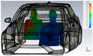 |
| 8.5 | 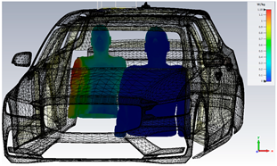 | 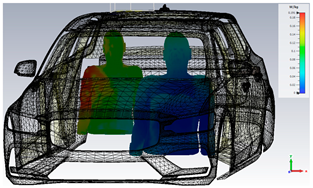 |
| 28 | 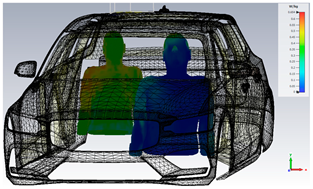 |  |
| 55 | 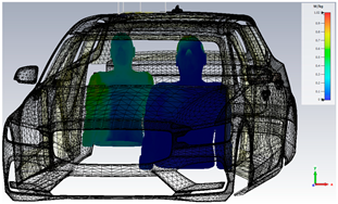 |  |
| 80 | 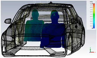 |  |
| fr (GHz) | 1 g | 10 g |
|---|---|---|
| 3.4 |  | 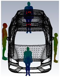 |
| 8.5 | 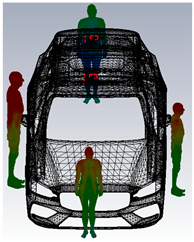 |  |
| 28 | 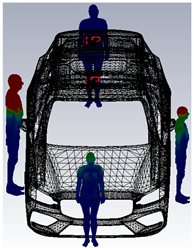 |  |
| 55 |  | 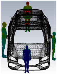 |
| 80 | 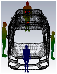 |  |
| Ref. | BW (GHz) | Polarization | Max. Gain (dBi) | Max. Efficiency (%) | Enhancement Techniques | Dim (mm × mm) | Applications |
|---|---|---|---|---|---|---|---|
| [1] | 25.99–31.49, 5.5 | N/A | 8.48 | 93.8 | Parasitic elements and corrugations | 33.83 × 16 | Directional 5G communication, imaging, or sensing |
| [5,7] | 25.13–37.74, 12.61 | N/A | 11.13 | 78 | Corrugations and metamaterials | 14 × 33 | 5G communications |
| [14] | 2.45, 2.6, 3.4, 28 | Multi | 9 | N/A | Tapered slot antenna (TSA) | >60 Diam | 5G-V2X |
| [24] | 28 | N/A | 6.2 | 39 | mm-wave on-glass antenna | 25 × 25 | Vehicular |
| [33] | 11–16 | N/A | 12 | >88 | SSPP LWA, hole-shaped SSPP TL | 200 × 30 | Imaging radar |
| [34] | 6–15 | N/A | 12 | 95 | SSPP LWA | 404 × 80 | Planarly integrated communication systems |
| [47] | 55–66, 11 | N/A | 14.86 | 90.2 | DSVA, corrugations, and grating elements | 70 × 40 | High-speed 5G communications |
| [48] | 16.5–18 | CP/LP | 12.54 | 98.5 | Half-mode substrate-integrated waveguide LWA | 170 × 35 | Vehicular |
| [49] | 56.3–63.4 | CP | 13.47 | >62 | Single layer SIW | 320 × 20 | V2V |
| [50] | 24.6–42.1, 50.1–52.5 | N/A | 6.72 | 98.7 | Collinear planar | 22 × 13 | V2X |
| [51] | 2.6, 3.9, 5.6 | N/A | 5.9 | N/A | U-shaped structure | 120 × 120 | Vehicular |
| [52] | 27.5–32 | N/A | <15 | <90 | SSPP | 65 × 20 | 5G applications |
| [53] | 8–14 | N/A | <8 | N/A | SSPP | 269 × 63.24 | Computer vision aids, VC |
| [54] | 8–12 | N/A | <10 | <95 | SSPP | 55 × 30 | Localization in X-band |
| [55] | 4–6.5 | N/A | 8.5 | N/A | CPW SSPP | 120 × 87.5 | Beyond fifth generation |
| This work | 3.32–4.28 8.45–11.7 16.66–18.45 23.67–27.26 31.67–34.57 52.3–61.67 71.8–82.5 | CP, Dual | 11.6, 14.5 on car | <92 | LWA SSPP | 14 × 12 | 5G, B5G, and vehicular communication |
Disclaimer/Publisher’s Note: The statements, opinions and data contained in all publications are solely those of the individual author(s) and contributor(s) and not of MDPI and/or the editor(s). MDPI and/or the editor(s) disclaim responsibility for any injury to people or property resulting from any ideas, methods, instructions or products referred to in the content. |
© 2025 by the authors. Licensee MDPI, Basel, Switzerland. This article is an open access article distributed under the terms and conditions of the Creative Commons Attribution (CC BY) license (https://creativecommons.org/licenses/by/4.0/).
Share and Cite
Saeidi, T.; Saleh, S.; Timmons, N.; McDaid, C.; Al-Gburi, A.J.A.; Razzaz, F.; Karamzadeh, S. High-Gain Miniaturized Multi-Band MIMO SSPP LWA for Vehicular Communications. Technologies 2025, 13, 66. https://doi.org/10.3390/technologies13020066
Saeidi T, Saleh S, Timmons N, McDaid C, Al-Gburi AJA, Razzaz F, Karamzadeh S. High-Gain Miniaturized Multi-Band MIMO SSPP LWA for Vehicular Communications. Technologies. 2025; 13(2):66. https://doi.org/10.3390/technologies13020066
Chicago/Turabian StyleSaeidi, Tale, Sahar Saleh, Nick Timmons, Christopher McDaid, Ahmed Jamal Abdullah Al-Gburi, Faroq Razzaz, and Saeid Karamzadeh. 2025. "High-Gain Miniaturized Multi-Band MIMO SSPP LWA for Vehicular Communications" Technologies 13, no. 2: 66. https://doi.org/10.3390/technologies13020066
APA StyleSaeidi, T., Saleh, S., Timmons, N., McDaid, C., Al-Gburi, A. J. A., Razzaz, F., & Karamzadeh, S. (2025). High-Gain Miniaturized Multi-Band MIMO SSPP LWA for Vehicular Communications. Technologies, 13(2), 66. https://doi.org/10.3390/technologies13020066