Article

Using Plasma Electrolytic Polishing for Post-Processing of Additively Manufactured Ti6Al4V Alloy Products

by
Sergey N. Grigoriev
,
Ivan V. Tambovskiy
,
Tatiana L. Mukhacheva
,
Ivan R. Palenov
,
Vladislav A. Gaponov
,
Irina A. Kusmanova
,
Artem O. Komarov
,
Artem P. Mitrofanov
,
Igor V. Suminov
and
Sergei A. Kusmanov
*
Department of High-Efficiency Machining Technologies, Moscow State University of Technology “STANKIN”, 127994 Moscow, Russia
*
Author to whom correspondence should be addressed.
Technologies 2025, 13(12), 553; https://doi.org/10.3390/technologies13120553
Submission received: 3 October 2025 / Revised: 23 November 2025 / Accepted: 24 November 2025 / Published: 27 November 2025
(This article belongs to the Section Innovations in Materials Science and Materials Processing)

Abstract

One of the limitations of additive manufacturing technology is the high surface roughness of finished products caused by the layered structure of the deposition and the effect of adhesion of unfused powder particles. This worsens the fatigue characteristics, wear resistance, and functional properties of the parts, which are especially important for critical applications in medicine, aviation, and mechanical engineering. The paper presents the results of a study on the possibility of using plasma electrolytic polishing for post-processing of products made of additively manufactured Ti6Al4V alloy to form a homogeneous surface with reduced roughness. The morphology, roughness, and tribotechnical characteristics of the surface after processing in a fluoride electrolyte were studied with varying voltage and polishing time. A 90% reduction in surface roughness is achieved by polishing at 300 V for 20 min. The results of tribological tests revealed that after the polishing of the oxidative wear mechanism is maintained, the temperature in the tribological contact zone decreases, and the load-bearing capacity of the surface increases (the Kragelsky–Kombalov criterion decreases). The greatest decrease in the friction coefficient by 2.1 times was observed with minimal surface roughness, when the largest average radius of rounding of the microprotrusions of the friction track microtopology is formed with a low value of the Kragelsky–Kombalov criterion.

1. Introduction

Additive manufacturing technologies, or 3D printing, in particular, selective laser melting (SLM), open up new possibilities in the production of complex-shaped parts. The existing potential for repair and restoration of expensive structural components is being developed [1,2,3].
One of the key materials used in SLM is Ti6Al4V titanium alloy, which has high specific strength and corrosion resistance [4,5,6], as well as biocompatibility [7]. This allows this alloy to be used in aerospace, medical, mechanical engineering and other industries [8,9,10].
However, a significant limitation of this additive manufacturing technology remains the high roughness of the surface of finished products, caused by the layered structure of the deposition and the effect of adhesion of particles of unfused powder [11,12]. This worsens the fatigue characteristics, wear resistance and functional properties of the parts, which are especially important for critical applications in medicine, aviation, and energy.
Traditionally, mechanical treatment methods such as surface mechanical treatment [13], mechanical shot peening [14], laser shot peening [15,16,17], and ultrasonic surface rolling [18] are used to reduce roughness. However, their effectiveness is limited when processing products with complex geometry, internal cavities, and small elements, where not only high precision but also uniform processing is required. In this regard, alternative finishing methods such as chemical [19] and electrochemical [19,20] polishing, electropolishing [21], electro mechano-chemical polishing [22], and electrical discharge polishing [23] are being actively studied. Recently, plasma electrolytic polishing (PEP) has demonstrated significant potential due to the possibility of processing hard-to-reach areas and achieving low roughness without mechanical action.
PEP belongs to a group of methods based on the surface treatment of metal products in electrolytic plasma [24]. The vapor-gas envelope, which is formed between the surface being treated and the electrolyte, has a physicochemical effect on the workpiece (heating, electrochemical dissolution, erosion under the action of microdischarges, etc.). It is possible to carry out chemical–thermal treatment with heating of the surface and diffusion saturation with nitrogen, carbon, and boron, which leads to the formation of hardened diffusion layers with improved performance characteristics. For example, saturation of low-carbon steels with carbon followed by hardening makes it possible to obtain hard martensitic structures on the surface while preserving a ductile core [25,26]. Diffusion of nitrogen and carbon into medium-carbon steels allows for surface hardening and significantly increases wear resistance [27,28]. Improvement of operational characteristics also occurs during the processing of alloy steels [29,30]. The second direction is the application of protective oxide coatings on various metals, including widely used titanium [31,32] and magnesium [33] alloys, as well as rarely encountered alloys based on zinc [34], niobium and tantalum [35].
During the PEP process, microdischarges in the vapor-gas envelope have a destructive effect on the surface relief protrusions, gradually smoothing the surface to a mirror finish [36,37,38]. This method is applicable after mechanical processing to reduce surface roughness as a finishing treatment [39,40]. In contrast to chemical and electrochemical polishing, PEP uses more environmentally friendly electrolyte solutions, and the absence of continuous contact of the electrolyte with the entire surface profile reduces material losses. The PEP has proven itself for processing various materials, including titanium alloys obtained by traditional methods [41,42,43].
Research into the use of PEP for post-processing of additively manufactured Ti6Al4V components is a relevant and important topic. However, there are several gaps and shortcomings in this area that are worth paying attention to. Additively manufactured components may have unique microstructural characteristics (e.g., residual stresses, porosity), which will influence the PEP process. There is a need to understand the optimal PEP process parameters (voltage, processing time, and electrolyte composition) to achieve the desired surface characteristics. Although it is known that PET can improve the surfaces of metal components, there is a lack of research elucidating the mechanisms of interaction between electrolyte plasma and the surface of additively manufactured Ti6Al4V.
This work aims to study the possibility of using the PEP for post-processing of products made of additive manufactured Ti6Al4V alloy to form a homogeneous surface with reduced roughness. In addition, the effect of polishing on the tribotechnical characteristics of the surface is investigated.

2. Materials and Methods

2.1. Materials

Finely dispersed Ti6Al4V titanium alloy powder (JSC “Normin”, Borovichi, Russia) with a declared particle size distribution of 20–63 µm was taken to build the samples for the study. The samples were manufactured using a Farsoon FS121M industrial SLM system (Farsoon Technologies, Changsha, China). The machine was equipped with a 500 W Nd:YAG laser with a wavelength of 1064 nm and a laser beam diameter of 50 µm. For fabrication, the manufacturer’s recommended process parameters of scanning speed v = 1100 mm/s and laser power of P = 200 W were used.
During the 3D printing process, under the influence of high temperatures with short-term irradiation by a high-power laser, the metal powder in the area of impact was melted to form a melt pool. After the local impact on the surface ceased, during the melting of other areas, the melt pool cooled and crystallized. Thus, according to the 3D model, samples from metal powder of Ti6Al4V titanium alloy were manufactured layer by layer.

2.2. Processing

SLM samples of Ti6Al4V titanium alloy of cylindrical shape with height of 10 mm and diameter of 11 mm were processed on the experimental setup designed for plasma electrolytic chemical–thermal treatment and polishing (Figure 1). PEP was carried out in an aqueous solution of electrolyte containing 2.5% ammonium fluoride (NH4F), with varying voltage (250–350 V) and time (5–20 min) of the process. The specified ammonium fluoride concentration is sufficient to achieve the electrolyte conductivity required for PEP. The selected processing duration within the specified range is determined by the fact that with shorter polishing times, no visual reduction in roughness is observed, while with longer polishing times, the roughness does not decrease while the material continues to dissolve. The specified voltage range is limited by the minimum value at which the vapor-gas envelope can form and polishing can occur, as well as the maximum value, above which the continuous vapor-gas layer breaks down and electrolyte splashes.
During PEP, the processed sample (active electrode) was connected to the positive terminal of the power source (the anode). The electrolytic cell was connected to the negative terminal of the power source (the cathode). The total electric power of the power source was 15 kW.
The SLM samples were fixed on a metal current lead and, after voltage was applied, were immersed in a cylindrical electrolytic cell with a diameter of 150 mm and a height of 250 mm using a vertical drive. The working electrolyte solution was continuously fed into the cell through a pipe located at the bottom of the cell. In the upper part of the electrolyzer, the electrolyte overflowed into an external bath, from where it was pumped through a double-circuit heat exchanger. The electrolytic cell, the bath body, the heat exchanger body and the coil inside it were made of AISI304 steel. The electrolyte solution was pumped through the coil, and tap water was fed into the main volume of the heat exchanger (about 0.05 m3). The tap water inside the heat exchanger was heated using a 3 kW fluoroplastic electric heating element, which was also installed in the body. The heated water inside the heat exchanger heated the working electrolyte solution through a coil, the temperature of which was maintained at 90 ± 2 °C during PEP using a digital thermostat. Depending on the temperature of the working electrolyte solution, the thermostat turned on or off the fluoroplastic electric heater inside the heat exchanger.
The circulation rate of the working electrolyte solution in the system was 1.0 L/min and was controlled using a turbine-type sensor. The sensor was installed in a polypropylene pipeline connecting all units of the installation (electrolyzer cell, external bath, heat exchanger, pump, and filter) to ensure the circulation of the electrolyte in a closed circuit. The electrolyte flow rate was set using a polypropylene ball valve with a polyphenylene sulfone ball, which was installed on the pipeline.
Before and after PEP, the SLM samples were washed using an ultrasonic bath in distilled water and acetone, then dried and weighed on a CitizenCY224C electronic analytical balance (ACZET (Citizen Scale), Mumbai, India) with an accuracy of ±0.0001 g.

2.3. Sample Testing

Morphological analysis of the surface of SLM samples and the surface of friction tracks was carried out using a Tescan Vega 3 scanning electron microscope (SEM) (Tescan, Brno, Czech Republic).
Elemental analysis of the friction track surfaces was carried out using an Energy-dispersive X-ray (EDX) analysis detector (Oxford Instruments, Abingdon, UK).
Friction tests were carried out using the shaft-bushing scheme [44]. The counter body was made of alloy tool steel (wt. %: 0.9–1.2 Cr, 1.2–1.6 W, 0.8–1.1 Mn, 0.9–1.05 C) in the form of a plate with a semicircular recess with a diameter of 11 mm, covering the surface of the sample. Tests were carried out in the dry friction mode under a load of 10 N. The sliding speed of the sample along the counter body was 1.555 m/s. The friction distance was 1000 m.
The measurement of the surface roughness and parameters of the microgeometry of the friction tracks was carried out using the Bruker Dektak XT Profilometer (Bruker, Karlsruhe, Germany). Waviness and roughness were distinguished using the profilometer’s built-in algorithms, which calculate parameters according to a series of international ISO standards. The base measurement length was 2.5 mm. The maximum number of data points per scan was 120,000. The standard deviation per step did not exceed 0.1 µm. The vertical measurement range was 1 mm with a maximum resolution of 0.1 nm. A total of 15 measurements were taken in each of two mutually perpendicular directions. The results represent an average of 30 measurements.
The nature of the plasma electrolytic treatment and subsequent tribological tests determine the formation of micro-roughness or roughness on the surface of the samples. In addition, the surface of the samples has a heterogeneous structure and under the action of the load applied during tribological tests, various structural components are deformed differently. Structural heterogeneity also contributes to the integral roughness of the surface. All of the above leads to discreteness of the contact of the sample with the counter body. The area of true or actual contact is only a part of the nominal contact area. The actual contact area was determined based on the microgeometry parameters taken by a profilometer directly from the friction tracks, according to the methods described in detail in [44]. In addition, the radii of curvature of the roughness protrusion tips and the average roughness, determined by the dimensionless Kragelsky–Kombalov criterion, were calculated based on the profilometry data.

3. Results

3.1. Surface Morphology and Roughness

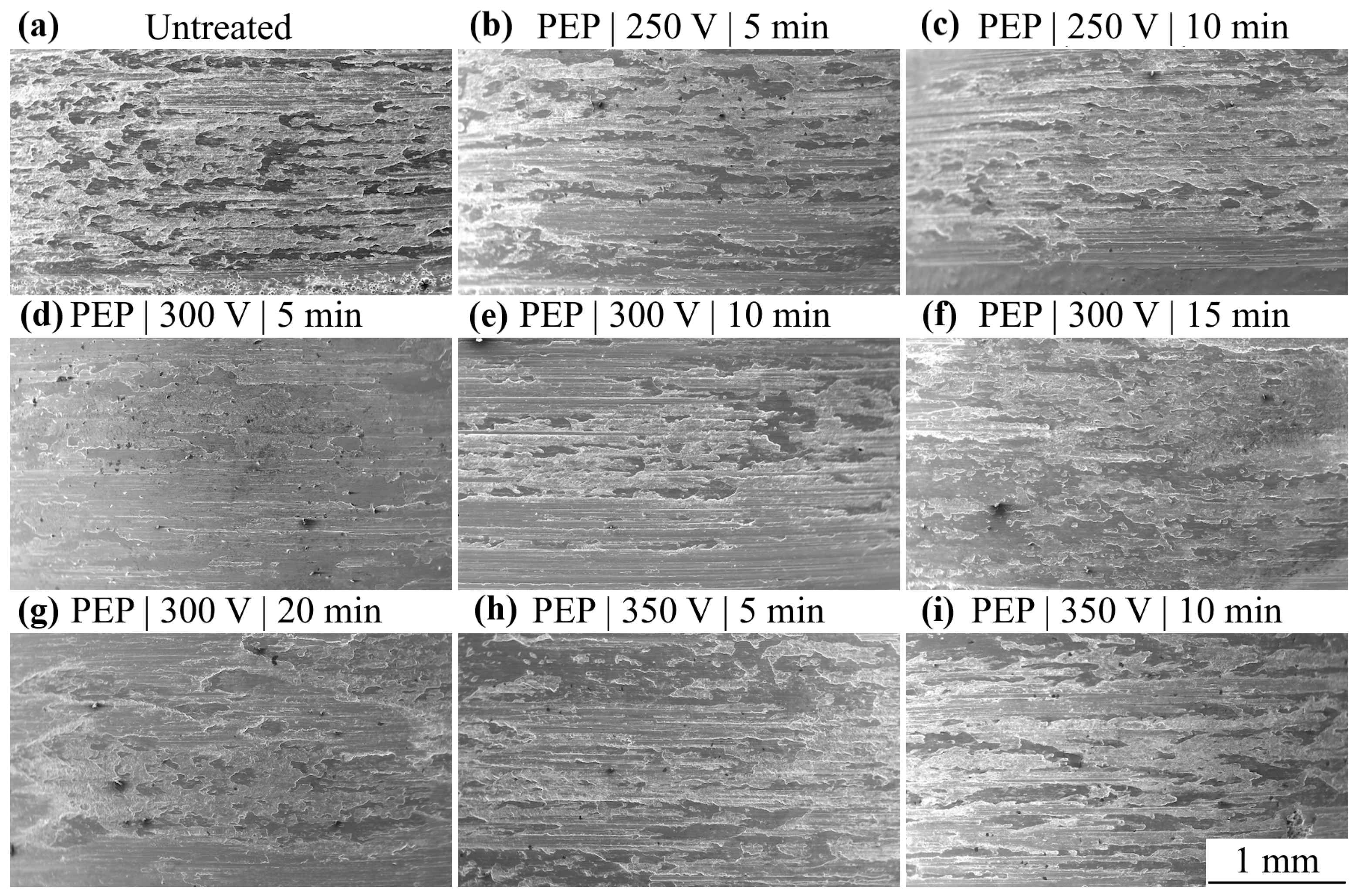
The surface of the SLM samples after 3D printing has a highly developed relief (Figure 2a). Spherical particles of fine metal powder do not melt completely at the final stages of product manufacturing (in the upper layers). During melt crystallization during cooling, unmelted particles firmly bond to the substrate, forming roughness profile protrusions. As a result, unmelted particles on the surface worsen its characteristics, which ultimately depend on the fraction of metal powder used and the 3D printing process parameters. The average Ra and Rz surface roughness of the SLM samples made of Ti6Al4V titanium alloy after manufacturing was 6.4 ± 0.8 and 34.2 ± 3.9 μm, respectively.
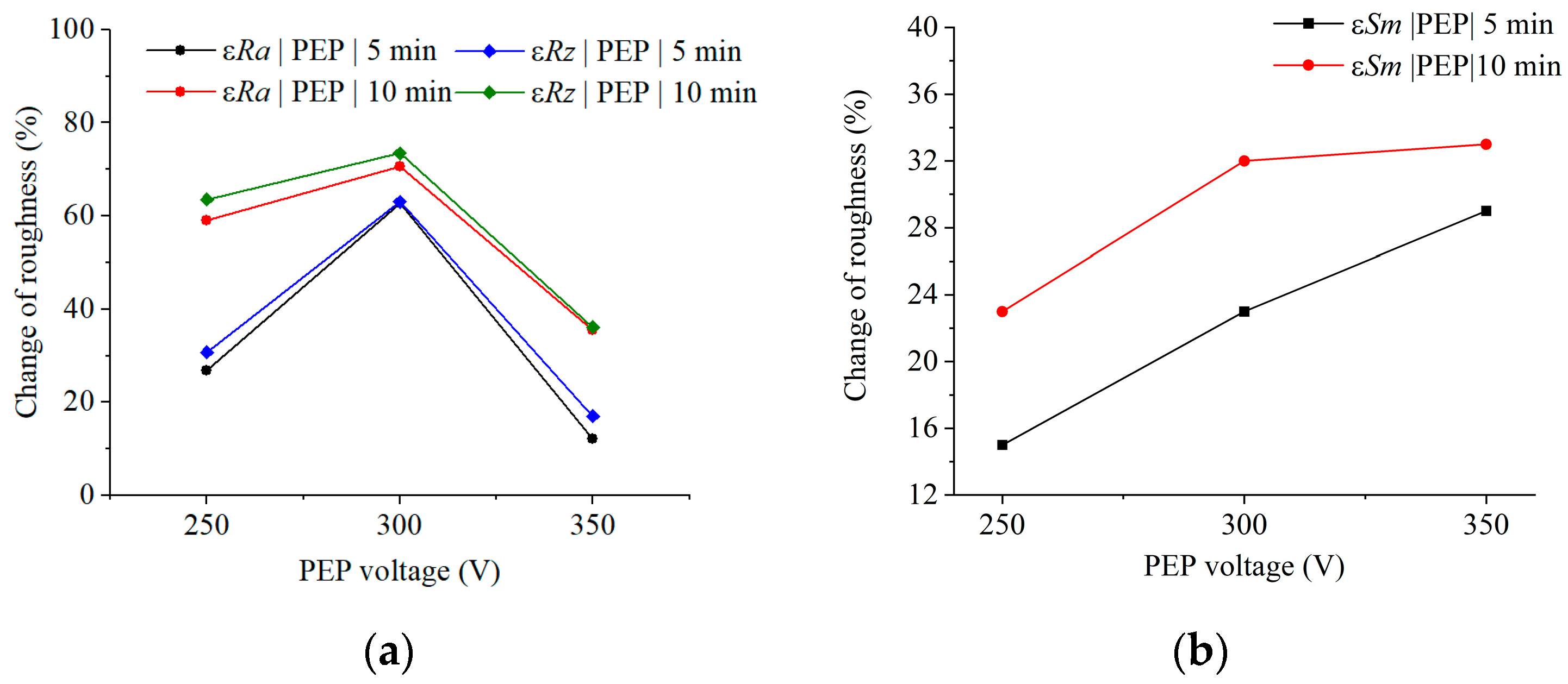
PEP for 5 min at 250 V ensures dissolution of spherical particles on the surface of SLM samples (Figure 2b). At the same time, boundaries of melt pool crystallization regions, characterized by protrusions and depressions of the roughness profile, can be observed on the surface. In general, after PEP under these conditions, the surface roughness of SLM samples in terms of εRa and εRz parameters decreases by 26.9 and 30.8%, respectively (Figure 3a), compared to the values before treatment. εRa and εRz refer to the relative change in roughness, equal to the ratio of the difference in roughness before and after PEP to the initial roughness before PEP. The average distance between roughness profile irregularities increases by 15%, which also indicates surface smoothing (Figure 3b). Increasing the polishing time to 10 min increases the efficiency of PEP, which is reflected in a decrease in εRa and εRz roughness by 59.0 and 63.9%, respectively, and an increase in εSm by 23%. However, boundaries of melt pool crystallization regions are still traceable (Figure 2c).
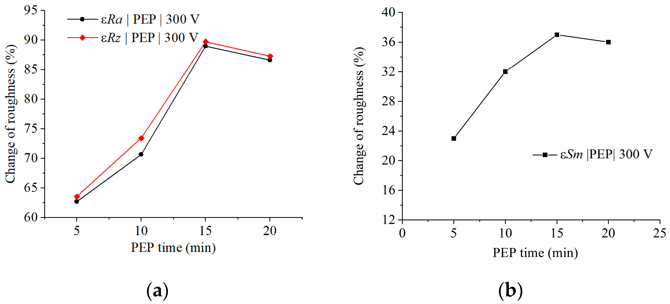
With increasing voltage of the PEP to 300 V, the surface of the SLM samples is subjected to more intense anodic dissolution. This is confirmed by the presented SEM images of the surface (Figure 2d–g). In this case, polishing for 5 min leads to a decrease in roughness in terms of Ra and Rz parameters by 62.7 and 63.5%, respectively (Figure 3a and Figure 4a), which is more than two times more effective than PEP of the same duration at a voltage of 250 V. The relative average distance between roughnesses increases by 23% relative to the initial sample and by 8% relative to the polished one at a voltage of 250 V (Figure 3b). PEP for 10 min at a voltage of 300 V causes a decrease in εRa and εRz roughness by 70.7 and 73.4% compared to the initial values and an increase in the distance between uneven surfaces by 32%. Thus, in the first 5 min, the PEP process is accompanied by intensive anodic dissolution of unmelted spherical particles of metal powder and the boundaries of the crystallization regions of the melt baths, which makes it possible to achieve such efficiency due to an increase in the current density on the protrusions of the roughness profile.
Increasing the PEP time at 300 V allows improvement in the main result due to uniform electrochemical dissolution of the SLM sample surface (Figure 2d–g). The maximum reduction in roughness by parameters Ra and Rz, almost by 90%, is achieved after PEP for 15–20 min at a voltage of 300 V. The average distance between profile irregularities increases to 37% (Figure 4b). At the same time, a pronounced layering of the material is observed in the surface layer, associated with layer-by-layer 3D printing.
PEP at 350 V is less effective, which is due to the presence of a large number of depressions and protrusions on the surface of the samples (Figure 2h,i). After PEP for 5 min, the roughness in terms of Ra and Rz parameters decreases only by 12.2 and 17.0%, and after polishing for 10 min by 35–36%, respectively (Figure 3a). The resulting surface morphology is probably the result of competition between the processes of anodic dissolution of roughness profile protrusions, electrochemical etching and oxidation.
Measuring the weight of the samples before and after treatment allowed us to determine the patterns of anodic dissolution during the PEP process. The maximum average anodic dissolution rate of SLM samples made of Ti6Al4V titanium alloy is 11.3 mg/min and corresponds to the PEP for 5 min at a voltage of 300 V (Figure 5), when the surface of the material has the greatest roughness. This is due to the high dissolution rate of the roughness profile protrusions at the initial stages of the process. With an increase in the PEP time to 10–20 min, the rate of anodic dissolution decreases on average to 9.8 mg/min. The weight loss of SLM samples after PEP at a voltage of 300 V is 1.6–2.2 times higher than that of samples after PEP at a voltage of 250 V and 350 V. The discovered dependencies correlate with the previously described results and explain the highest efficiency of the PEP process at a voltage of 300 V.

3.2. Tribological Testing

As a result of tribological tests, no definite correlation of the friction coefficient with the PEP conditions was found (Figure 6, Table 1). A decrease in the friction coefficient occurs after polishing for 5 min at 250 V, for 20 min at 300 V and for 10 min at 350 V.
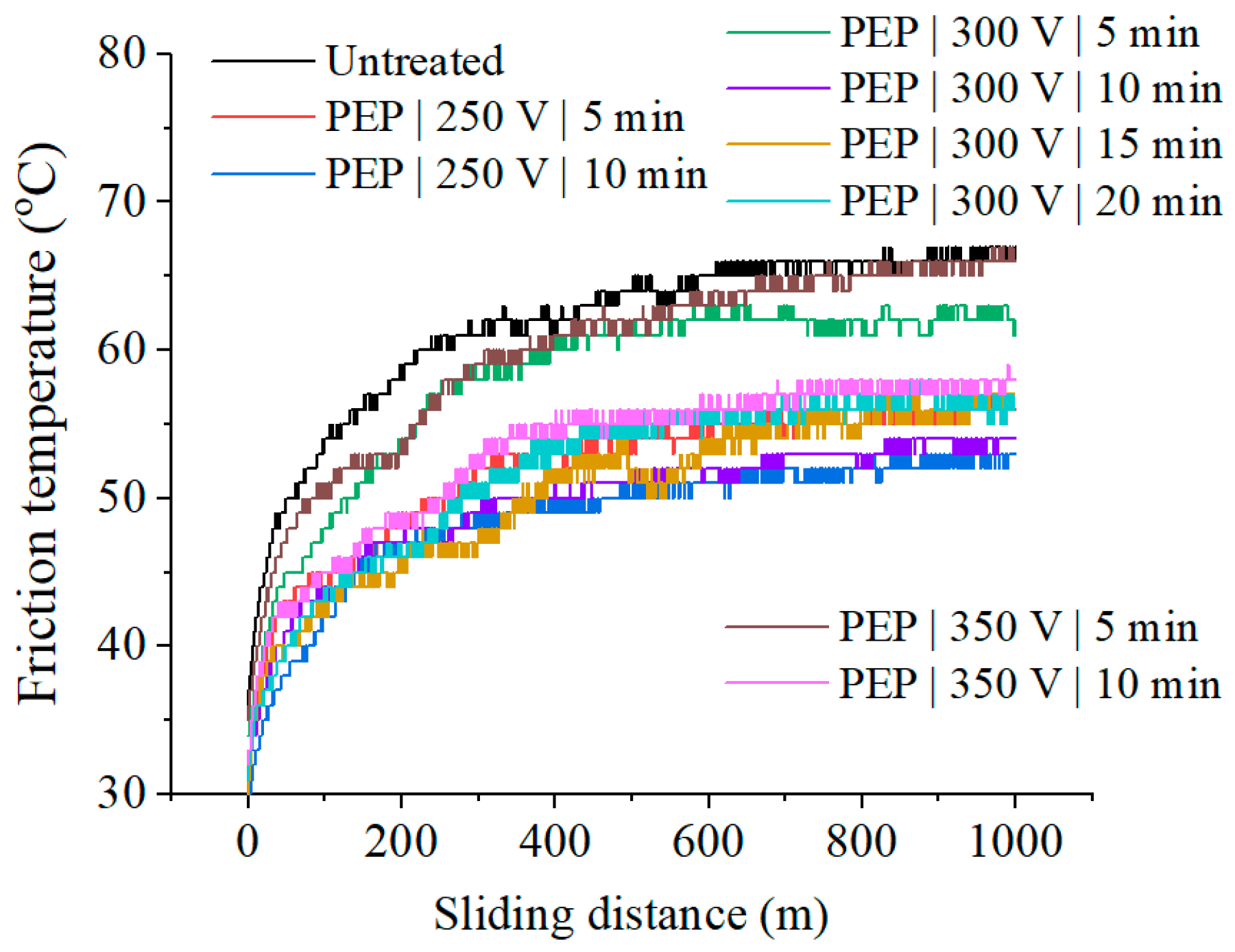
The temperature in the frictional contact zone decreases after PEP in all studied process modes (Figure 7, Table 1). The lowest temperature in the frictional contact zone is observed in samples after PEP for 10 min at a voltage of 250–300 V. There is no correlation between the friction coefficient and the temperature in the frictional contact zone.
The weight wear during friction remains virtually unchanged within the measurement error (Table 1). The weight loss during tribological testing correlates with a correlation coefficient of no less than R2 = 0.93 with wear determined by the friction track profiles (Figure 8).
The complex roughness criterion Δ, which includes both the height and step characteristics of the friction track profiles, the average radius of rounding of the roughness protrusions on the friction tracks of the samples after PEP is in most cases lower than that of the untreated sample (Table 1). This indicates an increase in the bearing capacity of the treated surface in tribocontact.
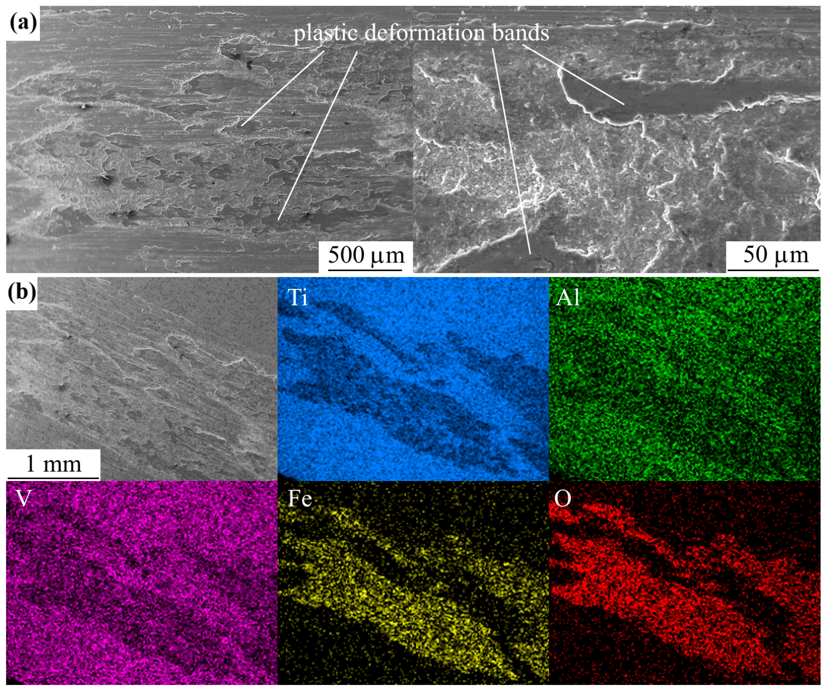
The friction tracks of all the studied samples show traces of oxidative wear (Figure 9), which are dimples of arbitrary shape. EDX analysis of the friction tracks also reveals oxygen (Figure 10 and Figure 11). When the oxide film peels off and before its next build-up, friction occurs along the metal substrate and the friction track images show stripes without sharp boundaries in the sliding direction. In addition, remnants of the counter body material were found on the worn surface.

4. Discussion

The key technological effect of PEP of titanium samples is the decrease in the height of the surface roughness protrusions. During PEP, the electric field strength is distributed over the surface of the processed titanium sample. The field strength is directly proportional to the gradient of the potential difference and, in each section, is inversely proportional to the thickness of the vapor-gas envelope that is formed around the sample during PEP, i.e., it is distributed over the surface of the part in accordance with its relief. At the roughness protrusions, the electric field strength is the highest and is capable of causing pulsed spark discharges. Spark discharges occur periodically between the roughness protrusions of the titanium sample, which is the anode during processing, and the electrolytic cell bath, which is the cathode. The energy released during the discharge is significant and has a smoothing effect on the tops of the protrusions.
In addition to spark discharges, roughness removal also occurs through anodic dissolution of micro roughness:
Me → Men+ + ne
The study of the morphology and roughness of the surface of SLM samples before and after PEP in a 2.5% ammonium fluoride solution at a temperature of 90 °C with varying voltage and time showed that the greatest smoothing of the surface relief is achieved after treatment at a voltage of 300 V for 15–20 min. The same PEP mode also corresponds to the greatest loss in sample weight during treatment. The linear dependence of the loss in sample weight on the PEP time (Figure 5) indicates a predominantly electrochemical mechanism for removing surface irregularities.
A comparison of the obtained results with polishing of products obtained by the traditional method [39,41] shows the need for a significant increase in the processing time, which correlates with the values of the initial surface roughness.
The absence of dependencies in friction of SLM samples after PEP under various conditions is due to the presence of a complex structure. The surface is characterized by chemical and structural heterogeneity due to the presence of impurities, structural defects, and grain boundaries. Therefore, the treated surface of titanium samples has unequal electrical properties. On the protruding surface roughnesses, the potential gradient has the highest value and therefore, a spark discharge acts on them, causing melting and smoothing of the tops. In addition, it is on the tops of the microprotrusions that the process of anodic dissolution begins. The components in the alloy surface have different dissolution rates, which also leads to the formation of irregularities on the sample surface. The above will affect the actual contact area of the rubbing bodies (Table 1) and their running-in at the initial stages of friction, which, in general, is reflected in the tribological behavior in each individual case.
Improved tribological characteristics of the SLM sample surface, as well as the greatest reduction in roughness, were demonstrated after treatment at a voltage of 300 V for 20 min by a 2.1-fold reduction in the friction coefficient (Table 1). Under these conditions, the largest average radius of rounding of the microprotrusions of the friction track microtopology and one of the smallest values of the Kragelsky–Kombalov criterion are formed.
The mechanism of oxidative wear is determined by plastic deformations occurring during friction, the bands of which are clearly visible in the images of friction tracks (Figure 10 and Figure 11). Plastic deformations lead to enrichment of the metal surface in the tribological conjugation zone with dislocations. As a result, the chemical activity of the metal in the friction contact zone increases, making the surface more susceptible to interaction with oxygen. Activated layers drawn into plastic deformation are covered with a thin oxide film. Considering that the lattice constant of titanium is less than that of its oxides, tensile stresses arise in the volume of titanium in the contact zone with the counter body during friction, and, on the contrary, compressive stresses arise in oxide films. Oxide films are characterized by low tensile strength. They are brittle due to the presence of structural defects and internal stresses. As the friction test time increases and the number of passes of the counter body over the sample increases, the oxide films crack and separate from the metal surface, then leaving the contact zone. After this, the oxide film grows again on the newly formed juvenile metal surface.

5. Conclusions

The positive effect of using plasma electrolytic polishing in ammonium fluoride solution for post-processing of Ti6Al4V titanium alloy products is shown. Because of PEP, a 90% reduction in surface roughness is achieved while forming its homogeneity due to the removal of unmelted spherical particles of finely dispersed metal powder. The best results are shown after PEP at a voltage of 300 V for 15–20 min.
The change in surface morphology after polishing affected the change in tribological properties of the surface. The absence of surface hardening did not affect the weight and volume wear of the treated surface by the hard counter body. At the same time, the decrease in surface roughness while maintaining the oxidative wear mechanism in polished samples, as in the untreated sample, determined the decrease in temperature in the tribological contact zone and the increase in the load-bearing capacity of the surface (decrease in the Kragelsky–Kombalov criterion). Under conditions of formation of the largest average radius of rounding of microprotrusions of the friction track microtopology and a small value of the Kragelsky–Kombalov criterion, the greatest decrease in the friction coefficient occurs. These conditions are met by treatment at a voltage of 300 V for 20 min, after which the friction coefficient decreases by 2.1 times compared to the untreated sample.
Further research may be related to the development of technological methods for processing complex-shaped products and internal surfaces, where the primary task will be to control physical and chemical processes under conditions of heterogeneity of the geometry of the surface being processed.

Author Contributions

Conceptualization, S.N.G. and S.A.K.; methodology, I.V.T. and T.L.M.; validation, I.A.K.; formal analysis, I.A.K.; investigation, I.V.T., T.L.M., I.R.P., V.A.G., A.O.K. and A.P.M.; resources, S.N.G. and I.V.S.; writing—original draft preparation, I.V.T., T.L.M., I.R.P., V.A.G., A.O.K., A.P.M. and S.A.K.; writing—review and editing, S.N.G., I.V.S. and S.A.K.; visualization, I.A.K.; supervision, I.V.S.; project administration, S.N.G.; funding acquisition, S.N.G. All authors have read and agreed to the published version of the manuscript.

Funding

This research was carried out with the financial support of the Russian Science Foundation within the framework of scientific project No. 21-79-30058-П.

Institutional Review Board Statement

Not applicable.

Informed Consent Statement

Not applicable.

Data Availability Statement

The original contributions presented in the study are included in the article, further inquiries can be directed to the corresponding author.

Acknowledgments

The study was carried out on the equipment of the Center of collective use of MSUT “STANKIN” supported by the Ministry of Higher Education of Russian Federation.

Conflicts of Interest

The authors declare no conflicts of interest.

Abbreviations

The following abbreviations are used in this manuscript:
SLMSelective laser melting
PEPPlasma electrolytic polishing
SEMScanning electron microscope
EDXEnergy-dispersive X-ray

References

  1. Kanishka, K.; Acherjee, B. A systematic review of additive manufacturing-based remanufacturing techniques for component repair and restoration. J. Manuf. Process. 2023, 89, 220–283. [Google Scholar] [CrossRef]
  2. Leino, M.; Pekkarinen, J.; Soukka, R. The Role of Laser Additive Manufacturing Methods of Metals in Repair, Refurbishment and Remanufacturing—Enabling Circular Economy. Phys. Procedia 2016, 83, 752–760. [Google Scholar] [CrossRef]
  3. Rahito Wahab, D.A.; Azman, A.H. Additive manufacturing for repair and restoration in remanufacturing: An overview from object design and systems perspectives. Processes 2019, 7, 802. [Google Scholar] [CrossRef]
  4. Leyens, C.; Peters, M. Titanium and Titanium Alloys: Fundamentals and Applications; Wiley-VCH: Weinheim, Germany, 2003. [Google Scholar] [CrossRef]
  5. Shrestha, S.; Panakarajupally, R.P.; Kannan, M.; Morscher, G.; Gyekenyesi, A.L.; Scott-Emuakpor, O.E. Analysis of microstructure and mechanical properties of additive repaired Ti–6Al–4V by Direct Energy Deposition. Mater. Sci. Eng. A 2021, 806, 140604. [Google Scholar] [CrossRef]
  6. Ochonogor, O.F.; Akinlabi, E.T.; Nyembwe, D. A review on the effect of creep and microstructural change under elevated temperature of Ti6Al4V alloy for Turbine engine Application. Mater. Today Proc. 2017, 4 Pt A, 250–256. [Google Scholar] [CrossRef]
  7. Rack, H.J.; Qazi, J.I. Titanium alloys for biomedical applications. Mater. Sci. Eng. C 2006, 26, 1269–1277. [Google Scholar] [CrossRef]
  8. Liu, S.; Shin, Y.C. Additive manufacturing of Ti6Al4V alloy: A review. Mater. Des. 2019, 164, 107552. [Google Scholar] [CrossRef]
  9. Samuel, M.P.; Mishra, A.K.; Mishra, R.K. Additive Manufacturing of Ti-6Al-4V Aero Engine Parts: Qualification for Reliability. J. Fail. Anal. Prev. 2018, 18, 136–144. [Google Scholar] [CrossRef]
  10. Li, C.; Pisignano, D.; Zhao, Y.; Xue, J. Advances in Medical Applications of Additive Manufacturing. Engineering 2020, 6, 1222–1231. [Google Scholar] [CrossRef]
  11. Galati, M.; Minetola, P.; Rizza, G. Surface Roughness Characterisation and Analysis of the Electron Beam Melting (EBM) Process. Materials 2019, 12, 2211. [Google Scholar] [CrossRef]
  12. Wang, P.; Sin, W.; Nai, M.; Wei, J. Effects of processing parameters on surface roughness of additive manufactured Ti-6Al-4V via electron beam melting. Materials 2017, 10, 1121. [Google Scholar] [CrossRef]
  13. Choudhary, S.; Gaur, V. Study of additively manufactured Inconel 718 with lanthanum zirconate coating. J. Alloys Comp. 2025, 1021, 179710. [Google Scholar] [CrossRef]
  14. Guo, C.; Wang, J.; Lu, H.; Wang, Y.; Bai, J.; Li, G.; Yin, Y.; Yao, L.; Zhu, Q.; Lu, J. Enhanced oxidation resistance of additively manufactured Inconel 718 superalloy by surface mechanical attrition treatment. Corros. Sci. 2025, 246, 112719. [Google Scholar] [CrossRef]
  15. Lv, J.; Luo, K.; Lu, H.; Wang, Z.; Liu, J.; Lu, J. Achieving high strength and ductility in selective laser melting Ti-6Al-4V alloy by laser shock peening. J. Alloys Compd. 2022, 899, 163335. [Google Scholar] [CrossRef]
  16. Yeo, I.; Bae, S.; Amanov, A.; Jeong, S. Effect of laser shock peening on properties of heat-treated Ti–6Al–4V manufactured by laser powder bed fusion. Int. J. Precis. Eng. Manuf.-Green Technol. 2021, 8, 1137–1150. [Google Scholar] [CrossRef]
  17. Lu, H.; Wang, Z.; Cai, J.; Xu, X.; Luo, K.; Wu, L.; Lu, J. Effects of laser shock peening on the hot corrosion behaviour of the selective laser melted Ti6Al4V titanium alloy. Corros. Sci. 2021, 188, 109558. [Google Scholar] [CrossRef]
  18. Zhou, C.; Yan, X.; Liu, D.; Xu, X.; Cui, J.; Li, M.; Yuan, C.; Li, H.; Liang, Y. Simultaneously achieving strength-ductility in additive-manufactured Ti6Al4V alloy via ultrasonic surface rolling process. Mat. Sci. Eng. A 2025, 920, 147555. [Google Scholar] [CrossRef]
  19. Tyagi, P.; Goulet, T.; Riso, C.; Stephenson, R.; Chuenprateep, N.; Schlitzer, J.; Benton, C.; Garcia-Moreno, F. Reducing the roughness of internal surface of an additive manufacturing produced 316 steel component by chempolishing and electropolishing. Addit. Manuf. 2019, 25, 32–38. [Google Scholar] [CrossRef]
  20. Cao, W.; Ghiotti, A.; Bruschi, S. Enhancing the Surface Quality of Additively Manufactured 316 Stainless Steel Revolving Parts through Electrochemical Polishing. Procedia CIRP 2025, 133, 615–620. [Google Scholar] [CrossRef]
  21. Ferchow, J.; Hofmann, U.; Meboldt, M. Enabling Electropolishing of Complex Selective Laser Melting Structures. Procedia CIRP 2020, 91, 472–477. [Google Scholar] [CrossRef]
  22. Kiran, K.U.V.; Mahey, V.; Kimbrel, B.; Roy, S. Surface finish enhancement of additively manufactured austenitic steel via novel sustainable electro mechano-chemical polishing. Mater. Today Commun. 2025, 42, 111434. [Google Scholar] [CrossRef]
  23. Boban, J.; Ahmed, A. Improving the surface integrity and mechanical properties of additive manufactured stainless steel components by wire electrical discharge polishing. J. Mater. Process. Technol. 2021, 291, 117013. [Google Scholar] [CrossRef]
  24. Yerokhin, A.L.; Nie, X.; Leyland, A.; Matthews, A.; Dowey, S. Plasma electrolysis for surface engineering. Surf. Coat. Technol. 1999, 122, 73. [Google Scholar] [CrossRef]
  25. Bayatanova, L.; Rakhadilov, B.; Kurbanbekov, S.; Skakov, D.; Popova, N. Fine structure of low-carbon steel after electrolytic plasma treatment. Mater. Test. 2021, 63, 842–847. [Google Scholar] [CrossRef]
  26. Belkin, P.N.; Dyakov, I.G.; Zhirov, A.V.; Kusmanov, S.A.; Mukhacheva, T.L. Effect of compositions of active electrolytes on properties of anodic carburization. Prot. Met. Phys. Chem. Surf. 2010, 46, 715–720. [Google Scholar] [CrossRef]
  27. Chongyang, N.; Tianlin, Z.; Yue, X.; Lixia, Y.; Guixiang, W. Study on preparation and friction characteristics of steel 1045 modified layer based on plasma electrolytic carbonitriding. Mater. Today Commun. 2022, 33, 104518. [Google Scholar] [CrossRef]
  28. Mukhacheva, T.L.; Belkin, P.N.; Dyakov, I.G.; Kusmanov, S.A. Wear mechanism of medium carbon steel after its plasma electrolytic nitrocarburising. Wear 2020, 462–463, 203516. [Google Scholar] [CrossRef]
  29. Kang, Q.-F.; Yang, W.-M.; Wei, K.-X.; Wang, D.-D.; Liu, X.-L.; Hu, J. Development of a Novel Plasma Aluminum-nitriding Methodology and Its Effect on the Microstructure and Properties for 42CrMo Steel. Surf. Technol. 2023, 52, 394–400. [Google Scholar] [CrossRef]
  30. Pérez, H.; Vargas, G.; Magdaleno, C.; Silva, R. Oxy-Nitriding AISI 304 Stainless Steel by Plasma Electrolytic Surface Saturation to Increase Wear Resistance. Metals 2023, 13, 309. [Google Scholar] [CrossRef]
  31. Aliofkhazraei, M.; Macdonald, D.D.; Matykina, E.; Parfenov, E.V.; Egorkin, V.S.; Curran, J.A.; Troughton, S.C.; Sinebryukhov, S.L.; Gnedenkov, S.V.; Lampke, T.; et al. Review of plasma electrolytic oxidation of titanium substrates: Mechanism, properties, applications and limitations. Appl. Surf. Sci. Adv. 2021, 5, 100121. [Google Scholar] [CrossRef]
  32. Apelfeld, A.; Grigoriev, S.; Krit, B.; Ludin, V.; Suminov, I.; Chudinov, D. Improving the stability of the coating properties for group plasma electrolytic oxidation. Manuf. Lett. 2022, 33, 54. [Google Scholar] [CrossRef]
  33. Jin, S.; Ma, X.; Wu, R.; Wang, G.; Zhang, J.; Krit, B.; Betsofen, S.; Liu, B. Advances in micro-arc oxidation coatings on Mg-Li alloys. Appl. Surf. Sci. Adv. 2022, 8, 100219. [Google Scholar] [CrossRef]
  34. Maltanava, H.; Stojadinovic, S.; Vasilic, R.; Karpushenkov, S.; Belko, N.; Samtsov, M.; Poznyak, S. Photoluminescent Coatings on Zinc Alloy Prepared by Plasma Electrolytic Oxidation in Aluminate Electrolyte. Coatings 2023, 13, 848. [Google Scholar] [CrossRef]
  35. Kim, S.-P.; Kaseem, M.; Choe, H.-C. Plasma electrolytic oxidation of Ti-25Nb-xTa alloys in solution containing Ca and P ions. Surf. Coat. Technol. 2020, 395, 125916. [Google Scholar] [CrossRef]
  36. Xiang, Y.; Sun, H.; Yang, D.; Ji, G.; Sun, L.; Duan, H.; Wang, J. Material removal model for describing the plasma discharge effect in magnetic-electrolytic plasma polishing. Int. J. Adv. Manuf. Technol. 2021, 131, 5023. [Google Scholar] [CrossRef]
  37. Danilov, I.; Hackert-Oschatzchen, M.; Zinecker, M.; Meichsner, G.; Edelmann, J.; Schubert, A. Process Understanding of Plasma Electrolytic Polishing through Multiphysics Simulation and Inline Metrology. Micromachines 2019, 10, 214. [Google Scholar] [CrossRef]
  38. Parfenov, E.V.; Farrakhov, R.G.; Mukaeva, V.R.; Gusarov, A.V.; Nevyantseva, R.R.; Yerokhin, A. Electric field effect on surface layer removal during electrolytic plasma polishing. Surf. Coat. Technol. 2016, 307, 1329–1340. [Google Scholar] [CrossRef]
  39. Witzke, K.; Kensbock, R.; Willsch, C.U.; Fricke, K.; Bekeschus, S.; Metelmann, H.-R. Mechanical and Plasma Electrolytic Polishing of Dental Alloys. Materials 2023, 16, 6222. [Google Scholar] [CrossRef]
  40. Kusmanov, S.A.; Tambovskiy, I.V.; Korableva, S.S.; Dyakov, I.G.; Burov, S.V.; Belkin, P.N. Enhancement of Wear and Corrosion Resistance in Medium Carbon Steel by Plasma Electrolytic Nitriding and Polishing. J. Mater. Eng. Perform. 2019, 28, 5425–5432. [Google Scholar] [CrossRef]
  41. Apelfeld, A.; Borisov, A.; Dyakov, I.; Grigoriev, S.; Krit, B.; Kusmanov, S.; Silkin, S.; Suminov, I.; Tambovskiy, I. Enhancement of Medium-Carbon Steel Corrosion and Wear Resistance by Plasma Electrolytic Nitriding and Polishing. Metals 2021, 11, 1599. [Google Scholar] [CrossRef]
  42. Yang, D.; Sun, H.; Wang, J.; Ji, G.; Duan, H.; Xiang, Y.; Fan, Y. The formation and stripping mechanism of oxide film on Ti6Al4V alloy surface during electrolytic plasma polishing. Surf. Coat. Technol. 2024, 478, 130469. [Google Scholar] [CrossRef]
  43. Ma, G.; Li, S.; Liu, X.; Yin, X.; Jia, Z.; Liu, F. Combination of Plasma Electrolytic Processing and Mechanical Polishing for Single-Crystal 4H-SiC. Micromachines 2021, 12, 606. [Google Scholar] [CrossRef] [PubMed]
  44. Mukhacheva, T.; Kusmanov, S.; Tambovskiy, I.; Podrabinnik, P.; Metel, A.; Khmyrov, R.; Karasev, M.; Suminov, I.; Grigoriev, S. Tribological properties of carbon tool steel after plasma electrolytic nitrocarburizing. J. Manufact. Mater. Process. 2023, 7, 197. [Google Scholar] [CrossRef]
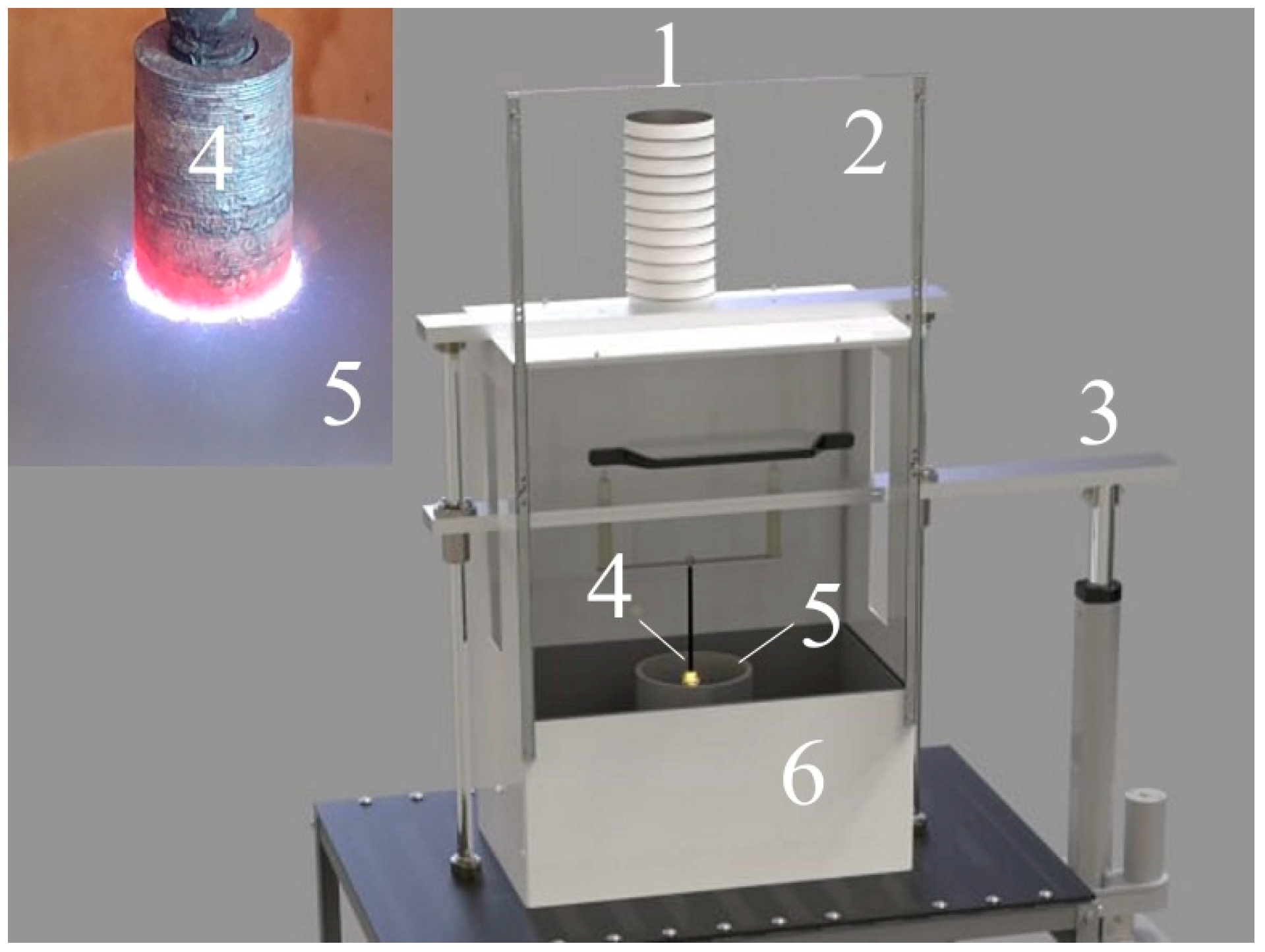
Figure 1. Plasma electrolytic polishing installation scheme: 1—ventilation duct; 2—protective screen of the working chamber; 3—linear drive; 4—workpiece-electrode (SLM sample); 5—cylindrical cell-electrode; 6—working chamber.
Technologies 13 00553 g001
Figure 2. SEM images of the SLM samples surface (a) before and after PEP with varying voltage and time: (b) 250 V and 5 min; (c) 250 V and 10 min; (d) 300 V and 5 min; (e) 300 V and 10 min; (f) 300 V and 15 min; (g) 300 V and 20 min; (h) 350 V and 5 min; (i) 350 V and 10 min.
Technologies 13 00553 g002
Figure 3. Relative change in (a) roughness by parameters εRa and εRz, and (b) the average distance between profile irregularities εSm on the surface of SLM samples after PEP at different voltages for 5 and 10 min.
Technologies 13 00553 g003
Figure 4. Relative change in (a) roughness by parameters εRa and εRz, and (b) the average distance between profile irregularities εSm on the surface of SLM samples after PEP at a voltage of 300 V and varying the PEP time.
Technologies 13 00553 g004
Figure 5. Dependence of the weight loss of SLM samples after PEP at different voltages on the PEP time.
Technologies 13 00553 g005
Figure 6. Dependence of the friction coefficient on the sliding distance for SLM samples before and after PEP.
Technologies 13 00553 g006
Figure 7. Dependence of the friction temperature on the sliding distance for SLM samples before and after PEP.
Technologies 13 00553 g007
Figure 8. Friction track profile of SLM samples before and after PEP.
Technologies 13 00553 g008
Figure 9. SEM image of the friction track of the SLM sample (a) before and after PEP: (b) 250 V and 5 min; (c) 250 V and 10 min; (d) 300 V and 5 min; (e) 300 V and 10 min; (f) 300 V and 15 min; (g) 300 V and 20 min; (h) 350 V and 5 min; (i) 350 V and 10 min.
Technologies 13 00553 g009
Figure 10. SEM image (a) and EDX maps (b) of the friction track of the untreated SLM sample.
Technologies 13 00553 g010
Figure 11. SEM image (a) and EDX maps (b) of the friction track of the SLM sample after PEP at 300 V for 20 min.
Technologies 13 00553 g011
Table 1. The tribological characteristics of samples before and after PEP at different voltages and PEP time.
U (V)t (min)μTfr (°C)Δmfr (mg)S (mm2)r (µm)Δ
25050.42 ± 0.0256.0 ± 0.42.1 ± 0.40.058320.311
100.86 ± 0.0452.8 ± 0.51.7 ± 0.30.0279.70.457
30050.68 ± 0.0362.4 ± 0.73.6 ± 0.50.05135.10.430
100.72 ± 0.0353.8 ± 0.42.1 ± 0.30.05936.20.461
150.78 ± 0.0456.2 ± 0.66.3 ± 0.70.09112.30.498
200.28 ± 0.0256.2 ± 0.52.7 ± 0.50.06448.40.370
35050.60 ± 0.0365.9 ± 0.82.8 ± 0.50.06134.80.412
100.36 ± 0.0257.7 ± 0.62.7 ± 0.40.06541.40.305
untreated0.60 ± 0.0366.5 ± 0.92.5 ± 0.40.06742.80.481
U is the voltage; t is the PEP time; μ is the average value of the friction coefficient over the last 100 m of distance; Tfr is the average temperature in the friction contact zone over the last 100 m of distance; Δmfr is the weight loss due to friction; S is the actual contact area; r is the average radius of curvature of the microprotrusion; Δ is the Kragelsky–Kombalov criterion.
Disclaimer/Publisher’s Note: The statements, opinions and data contained in all publications are solely those of the individual author(s) and contributor(s) and not of MDPI and/or the editor(s). MDPI and/or the editor(s) disclaim responsibility for any injury to people or property resulting from any ideas, methods, instructions or products referred to in the content.