Abstract
Free-form grid structures offer both aesthetic appeal and structural efficiency in long-span roof design and application, yet the potential of morphological design to optimize thermal performance has been long overlooked. This study proposes a multi-objective synergistic optimization framework which can improve the thermal environment and mechanical performance simultaneously for the roof. Focusing on public buildings in hot–humid climates, the research investigates the impact of roof geometry on indoor temperature under extreme thermal loading conditions and long-term thermal loading conditions. Furthermore, the evolution of thermal performance during mechanical performance-driven surface optimization is systematically analyzed. Subsequently, a dynamic proportional adjustment factor is introduced to explore the performance of the optimized results under different performance weights, with thermal and mechanical performance serving as the optimization objectives. Results demonstrate that thermal performance-driven optimization generates saddle-shaped free-form surfaces with alternating peak–valley configurations to achieve self-shadowing effects, reducing indoor temperature by approximately 2 °C but significantly compromising structural stiffness. Conversely, strain energy minimization yields moderate indoor temperature reductions, revealing a positive correlation between strain energy decrease and thermal performance improvement. In the multi-objective optimization considering thermal and mechanical properties, when the strain energy ratio is 0.5–0.7 (optimization balance zone), the indoor temperature decreases, while the structural stiffness and stability bearing capacity increase. This study provides a morphological–structural–environmental synergistic design reference for low-carbon long-span building roofs.
1. Introduction
With escalating global energy crises and environmental challenges, green architecture and energy-efficient design have emerged as pivotal directions in sustainable building practices [1]. Free-form grid structures, renowned for their architectural expressiveness and geometric flexibility, are widely adopted in large-span public buildings such as the Ottawa Light Rail Transit [2], Beijing Daxing International Airport [3], and the Court Roof of the British Museum [4]. However, public buildings account for a significant portion of energy consumption in the built environment. Achieving synergistic integration of aesthetic appeal, structural efficiency, and thermal performance in free-form grid structures remains a critical challenge, particularly harmonizing thermal performance optimization with form design to address energy demands under extreme climatic conditions.
Current free-form surface roof design primarily emphasizes structural mechanical performance, with increasing demands on stiffness, natural frequency, and stability bearing capacity. A strong correlation between geometric features and structural performance has been demonstrated in diverse applications, underscoring its universal significance [5]. Building on this focus, Cui et al. [6] proposed a height adjustment method for shape optimization of free-form grid structures, treating Z-coordinates of all mesh nodes as design variables. This approach effectively reduces strain energy and enhances stiffness in single-layer free-form grids [7]. Yang et al. [8,9] applied a multi-objective particle swarm optimization algorithm (MOPSO) to minimize strain energy and maximize the first natural frequency of NURBS-based structures by adjusting control point coordinates. Venuti and Bruno [10] investigated the influence of in-plane and out-of-plane stiffness parameters on the stability of free-edge reticulated shells. Through buckling mode analysis and load factor evaluation, they demonstrated that structural stability is critically governed by the bending stiffness of peripheral components and the shear stiffness of the shell itself. Complementing these findings, Ye et al. [11] quantified nodal stiffness using a geometric stiffness matrix, identifying the most unfavorable load patterns in spherical shells. These patterns correlate with significant gradients in joint well-formedness and minimal stability bearing capacity, highlighting the interplay between local geometric irregularities and global structural vulnerability.
Existing free-form structural design predominantly adheres to the principle of “mechanical performance dominance with architectural form compliance” often overlooking the intrinsic potential of surface geometry to regulate thermal performance. This design paradigm frequently necessitates supplementary building envelopes or active energy systems (e.g., air conditioner, heating) in later stages to compensate for inadequate thermal environmental performance. Particularly in large-span free-form grid structures, morphological design must transcend mechanical considerations by optimizing parameters such as surface material selection and spatial configuration to enhance thermal performance and achieve energy conservation and carbon reduction objectives. Traditional thermal performance improvements have primarily relied on passive insulation strategies [12,13]. For instance, Jyothis Anand demonstrated that enhancing solar reflectance is more effective than improving thermal emittance in developing passive daytime radiative cooling materials, as free-form geometries inherently maintain thermal emittance above 0.9 while directly influencing structural stiffness [14]. Integrating thermal performance into early-stage design through passive design strategies—leveraging architectural form optimization to improve thermal performance at structural design stage—could mitigate operational energy demands and reduce lifecycle costs, ultimately representing a more efficient design methodology.
Marko Bizjak et al. [15] investigated the relationship between solar heat gain and spatial form of building by varying design parameters such as orientation, deriving recommended values for each form type based on their impact on solar radiation exposure. In cold climate zones, Zhang Ran [16] conducted simulation studies on energy efficiency in office buildings, establishing quantitative relationships between morphological parameters—such as width, depth, and orientation—and energy consumption. This study identified optimal design configurations that are crucial for passive design strategies in office architecture. While minimizing solar heat gain is a straightforward optimization criterion, applying it solely to free-form surfaces may lead to reduced surface areas, compromising architectural expression and functional requirements. Therefore, energy-efficient optimization of free-form structures requires an integrated performance indicator that accounts for both solar radiation and spatial variability—similar to indoor temperature as a proxy for thermal comfort. Li Feng et al. [17] developed a comprehensive thermal comfort index, the Physiological Equivalent Temperature-based Climate Index (PETCI), incorporating multiple architectural metrics and seasonal factors, to explore the correlation between building morphology and microclimate thermal comfort in residential districts. Their findings revealed that building density has the most significant influence on PETCI, and they proposed corresponding optimization strategies to enhance thermal comfort. Pieskä et al. [18] focusing on thermal comfort as a key performance indicator, compared two geothermal high-temperature cooling systems under Mediterranean climatic conditions. The study highlighted their comparable thermal comfort performance while identifying differences in carbon emissions and electricity consumption, with an emphasis on improving overall energy efficiency.
Thermal performance optimization research has centered on building envelope systems for conventional structures, whereas thermal comfort improvements are frequently explored through urban-scale design strategies or energy-saving interventions in active systems. Despite advancements in architectural form design for aesthetic and structural integration, its influence on thermal performance remains underexplored. Research on free-form surface roof structures, for instance, predominantly emphasizes material-driven thermal performance enhancements, with limited attention to form-based strategies. However, under extreme climatic conditions, achieving synergies among aesthetics, functionality, mechanical performance, and thermal performance through morphological optimization remains a critical challenge. To bridge this gap, this study investigates the interplay between free-form geometry and thermal performance, as well as the coupling mechanisms between thermal performance and mechanical performance, and proposes a shape optimization framework that simultaneously reduces indoor surface temperatures and enhances structural stiffness. The method aims to advance both mechanical performance and thermal performance in single-layer free-form grid roofs, supported by numerical examples validating its efficacy.
The original aspects and principal contributions of this work are threefold: Firstly, it reveals that free-form roofs optimized for indoor temperature reduction under extreme/long-term thermal loading spontaneously evolve into saddle-shaped morphologies with peak–valley features to achieve self-shadowing effects. Secondly, it demonstrates that strain-energy-minimized shape optimization enables a unique thermo-mechanical synergy, leading to the concurrent reduction in both strain energy and indoor temperature. Finally, it innovatively introduces a dynamic proportional adjustment factor, which enables a dimensionless multi-objective optimization framework for practical thermal-mechanical balance in free-form roof design.
This paper is organized as follows: Section 2 outlines the methodological framework and presents the mathematical formulations of the optimization strategies employed in the validation process. Section 3 investigates the morphological characteristics of free-form surface roofs under different thermal performance scenarios, explores their structural behavior under mechanical performance constraints, and further examines how thermal performance evolves during mechanical optimization. Additionally, this section identifies the geometric patterns and structural responses of forms that achieve a balanced integration of both performance criteria. Section 4 concludes the study with a summary of key findings and implications for future research.
2. Methodology and Mathematical Formulation
2.1. Selection of Objective Function
In hot–humid climates, the demand for optimizing building form to manage solar radiation heat gain primarily aims to minimize redundant absorption by the building envelope. To investigate the impact of free-form surface roof geometries on the thermal environment, this study selects Haikou-a representative city in this climate zone-as the case study location. Climate data are derived from the 2024 EnergyPlus Weather File, and thermal simulations are conducted using EnergyPlus V23-1-0. Differing from traditional optimization approaches that focus solely on blocking solar radiation, this research innovatively incorporates the morphological adaptability of free-form surface roofs as a strategy to enhance thermal performance. The “zone operative temperature” is adopted as the key indicator for evaluating environmental comfort, referred to as “indoor temperature” (°C). This metric integrates air temperature and mean radiant temperature to reflect their combined influence on thermal sensation at the central point beneath the free-form surface roof. Air temperature serves as a quantitative measure of thermal performance, capturing the combined effects of solar radiation and spatial configuration changes on internal roof temperatures. The objective is to enhance thermal performance by minimizing the indoor temperature at the central point on the underside of the free-form surface roof through morphological modifications of its geometry. The model assumes a fully enclosed space, neglecting convective heat transfer, ventilation, infiltration, and internal heat sources or active cooling systems. This strategic simplification is critical for a controlled numerical experiment, as it effectively eliminates confounding variables from active systems or internal gains, thereby allowing us to quantify the passive thermal influence attributable solely to roof morphology. Additionally, the sub-roof space below the lowest point of the free-form structure is excluded from analysis. The computational domain is confined to a finite volume bounded by the free-form-surface roof surface and the roof base plane. This setup isolates the thermal performance of the roof geometry itself, ensuring focused evaluation of how varying solar radiation conditions affect indoor temperature. Such controlled conditions provide a scientific basis for architectural design optimization in hot-summer and warm-winter climates. While this constitutes a simplified representation, it provides a scientifically rigorous basis for understanding the core morphology-driven effects, a critical first step before introducing complex real-world factors.
The focus of this study is free-form surface roof structures, with the scope limited to opaque outer envelope structure. Following the methodology in reference [19], the solar absorptance of the building surface is set to 0.55, and the thermal absorptance is 0.9. Solar radiation heat gain is strongly influenced by architectural form, particularly the surface area exposed to sunlight and the angle between the facade or roof and incoming solar rays. Based on the principles of solar radiation heat gain calculation for opaque envelopes as outlined in [19], the indoor temperature can be expressed as:
In the equation, represents the air temperature (°C); denotes the mean radiant temperature (°C); n is the total number of surfaces within the zone; is the view factor from the central point on the underside of the roof to the i-th surface, which depends on the geometric configuration and relative positioning of the surfaces; and is the surface temperature of the i-th surface (°C), derived from the energy balance Equation (3):
In the equation, represents the heat gained by conduction through the building envelope (W); represents the heat gained by convection (W); represents the heat gained by radiation on the wall surface (W); and represents the heat gained by the surface from solar radiation (W). The thermal resistance R is 2.61 m2·K/W [14]. The convective heat transfer coefficient is given by , where the wind speed is obtained from EnergyPlus Weather File. The emissivity of the surface is taken as 0.9 [14]. The Stefan-Boltzmann constant is 5.67 × 10⁻⁸ W/m2K4. The solar irradiance incident on the surface (W/m2) is also derived from EnergyPlus Weather File. The surface area A is in square meters (m2). The sky temperature is calculated using the formula [20], where the dew point temperature and the outdoor air temperature (°C) are obtained from EnergyPlus Weather File.
In the equation, the zone air thermal capacity is given by , where is the density of air (1.225 kg/m3), V is the volume of the zone (m3), and is the specific heat capacity of air (1.005 kJ/(kg·K)).
2.2. Formulation of the Optimization Problem
- (1)
- Shape Optimization Incorporating Building Thermal Performance
Focusing on the thermal performance optimization of free-form surface grid structures in hot-summer and warm-winter climates (represented by Hainan Province), this study utilizes annual meteorological data to define two representative thermal loading scenarios. The peak radiation hours (09:00–16:00) on the hottest day of the year are selected as the extreme thermal loading conditions, under which the indoor thermal stability is evaluated. Meanwhile, the long-term thermal loading conditions are defined as the six hottest months of the year (April to September), aiming to assess the cumulative thermal performance and ensure seasonal climate adaptability. Shape optimization models of the free-form surface roofs are established with the objective of minimizing the indoor (average) temperature under both extreme and long-term thermal conditions, respectively. The mathematical formulations are expressed as follows:
In the equations, X represents the design variables of the structure, which are the nodal coordinates of key points that control the surface shape. XL and XU denote the lower and upper bounds of the design variables, respectively. represents the indoor temperature (°C) at each hour/month during the optimization iteration process. The lower bound XL and upper bound XU of the design variable X are defined as follows: XL = X0 − ΔL, XU = X0 + ΔU. X0 represents the initial value of the design variable, typically taken as the design variable of the initial structure. ΔL and ΔU are offset vectors for the lower and upper bounds, determined based on the designer’s preferences. For example, setting ΔL = ΔU= 2.0 E, where E is a vector with all elements equal to 1.0.
- (2)
- Shape Optimization under Vertical Static Load Conditions
For free-form surface grid Structures, the external load is a uniformly distributed vertical load (in the negative Z-direction), which is converted into constant nodal forces. with the minimum strain energy as the objective function, the structural optimization problem is formulated as follows:
In the equations, denotes the strain energy of the structure, is the load vector, and is the nodal displacement vector, with the superscript T indicating the transpose of the vector.
- (3)
- Shape Optimization Integrating Thermal Performance and Static Load
To address the multi-objective optimization problem involving both thermal performance and mechanical performance of free-form surface grid roofs, a bi-objective optimization model is established with the minimization of strain energy and indoor temperature as the dual objectives. Due to the differing physical dimensions and significant magnitude disparities between the two objective functions, a dynamic weighting adjustment method is employed. A dynamic proportional adjustment factor is introduced to normalize the objective functions, thereby enabling effective synergy in multi-objective optimization. The mathematical formulation is expressed in Equation (12):
In the formulation, denotes the initial strain energy of the structure (J), represents the initial indoor temperature (°C), and refers to the strain energy during the optimization iteration (J). The overall structural optimization objective is defined as a weighted sum of the strain energy under vertical loading and the indoor temperature . The parameter serves as the weighting factor that balances the relative contributions of the two objectives in the optimization process. To ensure comparability between these two objectives—which differ in both physical dimension and magnitude—an implicit non-dimensionalization approach combined with a dynamic weighting mechanism is adopted. Since the optimal value of may vary across different case studies, the specific value will be provided individually for each example.
2.3. Optimization Methodology
The optimization process employs a shape optimization approach based on the finite element method, utilizing the fmincon function from MATLAB R2024a’s Optimization Toolbox with the interior-point algorithm to solve nonlinear optimization problems with continuous variables. Structural mechanical information, such as displacement data, is obtained through finite element analysis using ANSYS 19.2. Indoor temperature and other performance metrics are derived from simulations performed in EnergyPlus, which serves as the modeling and building performance simulation platform. The morphological optimization design of free-form surfaces follows the basic steps outlined below (Figure 1):
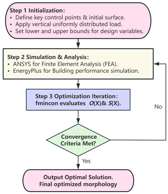
Figure 1.
Flow chart.
Step 1. Based on the architectural intent, key control points that define the initial free-form surface are specified, and the initial geometric model of the free-form surface is established. This includes defining the magnitude of the vertical uniformly distributed load acting on the structure, as well as the lower bound and upper bound for the design variables.
Step 2. Based on the initial structural information, including the design variables, a finite element model is established. MATLAB is used to invoke ANSYS for obtaining structural displacement data, and EnergyPlus is called to retrieve the indoor temperature of the structure. Computational modules for the objective functions—such as strain energy and indoor temperature—are then developed, ensuring proper data transfer and updating of structural information throughout the optimization process.
Step 3. The fmincon function is used to call the objective function, initiating the iterative process to compute the optimal solution. Once the maximum number of iterations is reached or other convergence criteria are satisfied, the fmincon function returns the optimal solution value and state information. The output parameters can be utilized to analyze the iteration process, providing insights into the accuracy and stability of the results.
2.4. Shape Factor
The shape factor is an important indicator for evaluating the efficiency of free-form surface roof geometries. It is defined as the ratio of the surface area in contact with the outdoor atmosphere to the enclosed volume of the building [21]. For free-form surface roofs, a lower shape factor indicates a reduced surface area per unit volume, which in turn leads to decreased thermal loss through the building envelope. The calculation formula is as follows:
In the equation, represents the shape factor of the building. denotes the surface area of the building that is in contact with the outdoor atmosphere, measured in square meters (m2). represents the volume enclosed by this surface area, measured in cubic meters (m3).
2.5. Solar Exposure Rate of Structural Surface
To quantify the self-shadowing effect of the roof model, the surface exposure ratio (SER) is used to calculate the proportion of surface sunlight exposure under extreme thermal loading conditions.
In the equation, represents the “Surface Outside Face Sunlit Fraction” value for the n-th surface at the t-th time point, which can take values of 0 or 1. denotes the total number of time points (hours), and represents the total number of surfaces.
2.6. Thermal Density (TD)
To quantify the thermal load efficiency per unit volume, the concept of Thermal Density (TD), as defined in Equation (15), is introduced based on a modified version of the conventional sensible heat load density [22]. TD characterizes the indoor temperature per unit building volume (°C/m3), reflecting the volume’s efficiency in regulating the thermal environment. A lower TD value indicates a smaller heat load per unit volume and superior thermal performance.
In the equation, denotes the sensible heat load density (W/m3), and represents the energy demand (W).
3. Validation with Numerical Examples
The numerical examples are primarily designed to investigate the morphological characteristics of free-form surface roof under the following three scenarios: ① Morphological patterns of different initial structures optimized for minimizing indoor temperature under extreme thermal loading and long-term thermal loading conditions; ② Comparison of morphological outcomes from the same initial structure under two optimization objectives: thermal performance (extreme thermal loading conditions) versus strain energy minimization; ③ Morphological characteristics under multi-objective optimization considering both thermal performance and structural strain energy. For this purpose, two model examples are designed, using a NURBS-based single-layer free-form grid structure as the initial computational model. To maintain structural symmetry and aesthetic appeal, a 1/4 symmetric model is adopted in the analysis. Example 1 analyzes a 30 m-span single-layer spatial grid structure with peripheral hinged supports, featuring a free-form surface geometrically defined by the NURBS Equation (16) [23] with degrees p = q = 3. The key control points form a grid array of (m + 1) × (n + 1), arranged from top to bottom and left to right. An additional point is inserted between every two adjacent design variables to refine the mesh. The initial structure is an axisymmetric shape, and 1/4 of the surface is selected based on two orthogonal symmetry axes. The design variables, symmetric control points, and constrained points are illustrated in Figure 2, with the initial values provided in Table 1. Example 2 adopts the same setup as Example 1, with its initial parameter values given in Table 2. In both examples, the structure faces north along the Y-axis, and a uniformly distributed vertical load of 2 kN/m2 is applied.
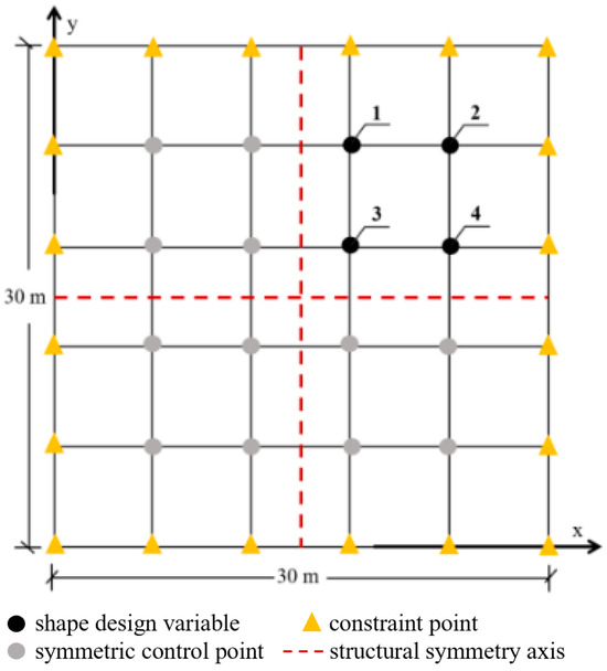
Figure 2.
Initial Structure and Shape Control Key Points.

Table 1.
Coordinates of Shape Control Key Points and Constrained Points for Example 1 (m).
Table 2.
Coordinates of Shape Control Key Points and Constrained Points for Example 2 (m).
In the equation, x, y, and z represent the coordinates of the generated NURBS free-form surface. The parameters u, v ∈ [0, 1], the parameters p and q are the orders of the B-spline basis functions, and m + 1 and n + 1 are the number of knots. (αi,j, βi,j, γi,j) denotes the combined coefficients of the B-spline basis functions, i.e., the control points. The combination coefficients (αi,j, βi,j, γi,j) of the B-spline surface are calculated according to the global surface interpolation method in Chapter 9 of reference [24]. When the p and q orders of the surface are specified, the knot vectors of the parameters u and v are determined by the chord length method. Thus, a set of key points on the surface can be uniquely used to generate the shape of the B-spline surface by the associated program [23].
Basic Structural Parameters: The structural members are hollow steel tubes with an inner diameter of 0.2 m and an outer diameter of 0.22 m. The steel material has an elastic modulus of 2.1 × 10⁵ MPa, a Poisson’s ratio of 0.3, and a mass density of 7850 kg/m3. The Von Mises yield criterion is adopted, with a plastic strength of 210 MPa and a yield strength of 400 MPa.
Structural mechanics performance analysis and computation is performed using the general-purpose finite element software ANSYS. For all numerical examples, the structural members are modeled using the BEAM188 element. The material’s elastic-plastic behavior is considered in the calculations. Buckling analysis is conducted using ANSYS’s eigenvalue buckling analysis, which yields the buckling load factors. Thermal performance analysis of the structure was carried out using EnergyPlus, with triangular surface elements employed for thermal simulation.
The coordinates of the surface control points are defined as the design variable X. The variation range of the design variable X is given as: xL = x0 − 1.5E, xU = x0 + 1.5E, yL = y0 − 1.5E, yU = y0 + 1.5E, zL = z0 − 0.0 E, zU = z0 + 4.0E. Here, x0, y0, z0 represent the initial values of the design variables as vectors composed of the x, y, and z components of the control points, which correspond to the initial structural nodal coordinates.
3.1. Patterns of Rational Surface Morphologies Under Thermal Performance Objectives
This section investigates the design patterns of free-form surface roof geometries by adopting the minimization of indoor temperature under both extreme thermal loading conditions and long-term thermal loading conditions as thermal performance objectives. By comparing and analyzing the indoor temperatures optimized by different initial models under these two objectives, the evolutionary outcomes of roof surface morphologies under varying thermal optimization goals are revealed.
① Model 1: In the optimization targeting extreme thermal loading conditions (Figure 3), the shape factor decreased gradually from 0.40 to 0.30, representing a 25% reduction, while the indoor temperature dropped from the initial value of 38.24 °C to 36.29 °C—a decrease of 1.95 °C. For the optimization under long-term thermal loading conditions (Figure 4), the shape factor was reduced from 0.40 to 0.29, corresponding to a 27.5% decrease, and the indoor temperature decreased from 30.96 °C to 30.14 °C, a reduction of 0.82 °C. Both optimization processes exhibit obvious stage characteristics: In the early stages, a strong positive correlation is observed between the reduction in shape factor and the decrease in indoor temperature. As the optimization approaches convergence, further improvements in thermal performance are achieved through localized adjustments to the surface morphology—such as modifying the distribution of concave or convex regions—leading to a decoupling between shape factor and indoor temperature. During this phase, the shape factor changes only slightly (approximately 0.05 for the daily case scenario and 0.03 for the long-term case). Under extreme thermal loading conditions, the thermal density (TD) decreased from an initial value of 0.0152 to 0.0070, a reduction of 53.95%. Similarly, under long-term thermal loading conditions, TD dropped from 0.0123 to 0.0056, a reduction of 54.47%. These results indicate a significant reduction in heat load per unit volume and an overall improvement in the building’s thermal performance.
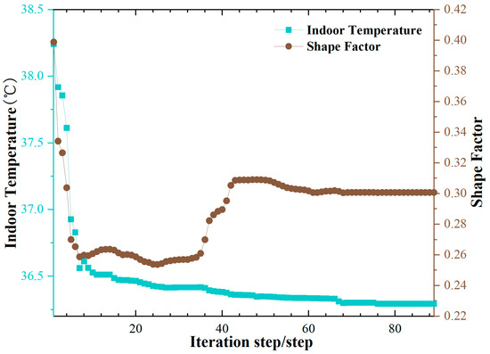
Figure 3.
Indoor Temperature & Shape Factor (Extreme)-Model 1.
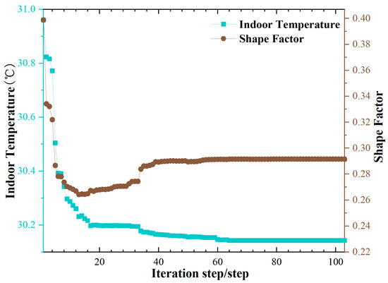
Figure 4.
Indoor Temperature & Shape Factor (Long-term)-Model 1.
The optimization patterns of the roof structure under both thermal objectives exhibit similar characteristics (Figure 5). The nodes in the central region of the B-spline free-form surface gradually move outward and upward, leading to a morphological evolution from an initial spherical shape to a saddle-shaped surface. The optimized roof forms develop an alternating pattern of “peaks” (convex regions) and “valleys” (concave regions), resulting in a self-shadowing effect. Notably, the concave areas are more pronounced in the central parts of the north and south facades, which aligns with the sun’s east-to-west movement trajectory. The initial solar exposure rate of structural surface (SER) was 99.13%, which decreased to 87.31% under the extreme thermal loading condition and to 88.75% under the long-term thermal loading condition, indicating a significant improvement in self-shadowing performance. Simultaneously, the mesh density in the central region of the roof gradually decreases, with elements shifting toward the mid-span of the structural edges. This results in a dome-like uplift in the center and the formation of four raised ridges extending along the diagonal directions of the plan. Consequently, the overall geometry becomes more compact, with a reduced surface area per unit volume.
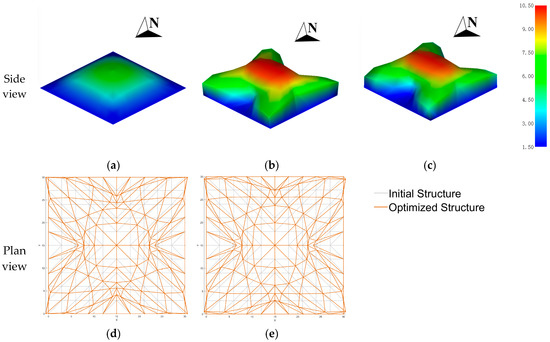
Figure 5.
Initial and optimized structure-Model 1: (a) Initial structure; (b) Optimized structure—Extreme; (c) Optimized structure—Long-term; (d) Structural framework—Extreme; (e) Structural framework—Long-term.
② Model 2: In the optimization targeting extreme thermal loading conditions (Figure 6), the shape factor decreased gradually from 1.14 to 0.44, representing a reduction of 61.40%, while the indoor temperature dropped from the initial value of 39.53 °C to 37.17 °C, a decrease of 2.36 °C. For the optimization under long-term thermal loading conditions (Figure 7), the shape factor was reduced from 1.14 to 0.41, corresponding to a 64.04% decrease, and the indoor temperature decreased from 31.55 °C to 30.52 °C, a reduction of 1.03 °C. Similarly to Model 1, the optimization process of Model 2 exhibits obvious stage characteristics: in the early stages, there is a strong positive correlation between the reduction in shape factor and the decrease in indoor temperature. In the convergence phase, however, the shape factor changes only slightly (within approximately ±0.01) and no longer synchronizes with the indoor temperature. Under extreme thermal loading conditions, TD decreased from an initial value of 0.0488 to 0.0116, a reduction of 76.23%. Similarly, under long-term thermal loading conditions, TD dropped from 0.0390 to 0.0096, a reduction of 75.38%. These results indicate a significant reduction in heat load per unit volume and an overall improvement in the building’s thermal performance.
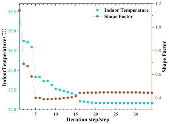
Figure 6.
Indoor Temperature & Shape Factor (Extreme)-Model 2.
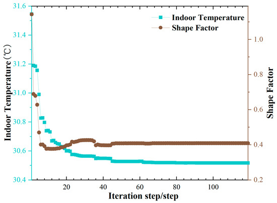
Figure 7.
Indoor Temperature & Shape Factor (Long-term)-Model 2.
Under both optimization objectives, Model 2 exhibits similar morphological evolution patterns in the roof structure (Figure 8). The nodes in the central region of the B-spline free-form surface gradually move outward and upward, leading to a transformation from an initial spherical shape to a saddle-shaped surface. The optimized roof develops an alternating pattern of “peaks” (convex regions) and “valleys” (concave regions), forming a self-shadowing surface morphology. The eastern and western portions of the roof remain relatively flat with minimal concavity, while more pronounced depressions appear in the central regions of the north and south facades—aligning well with the sun’s east-to-west trajectory, thereby achieving effective self-shadowing performance, similar to that observed in Model 1. The initial solar exposure rate (SER) of the roof surface was 100%, which decreased to 90.13% under the extreme thermal loading condition and to 89.75% under the long-term thermal loading condition, demonstrating a significant improvement in shading efficiency. Meanwhile, the mesh density in the central area of the roof gradually decreases, with elements shifting toward the mid-span of the structural edges. This results in a dome-like uplift at the center and the formation of four raised ridges extending along the diagonal directions of the plan. Consequently, the overall geometry becomes more compact, with a reduced surface area per unit volume.
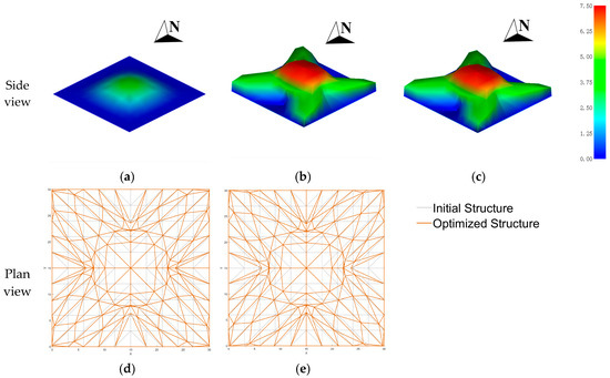
Figure 8.
Initial and optimized structure-Model 2: (a) Initial structure; (b) Optimized structure—Extreme; (c) Optimized structure—Long-term; (d) Structural framework—Extreme; (e) Structural framework—Long-term.
Through optimization, the free-form surface roof effectively improves the indoor thermal environment under extreme heat conditions, while maintaining structural aesthetics and functionality. Based on the optimization results of Model 1 and Model 2, it can be observed that the optimization targeting extreme thermal loading conditions achieves higher efficiency, with a more significant reduction in indoor temperature—approximately 2 °C. Both models exhibit similar morphological evolution patterns under the two thermal performance objectives: the central region of the optimized roof structure rises into a dome-like shape, and four ridges extend along the diagonal directions of the plan, forming a self-shadowing free-form morphology. The design solutions obtained under different optimization objectives show a high degree of consistency. To avoid redundancy and improve research efficiency, subsequent analysis will focus on the optimization of Model 1 under the extreme daily thermal loading condition for an in-depth investigation.
3.2. Thermal vs. Non-Thermal Effects on Surface Morphology
This section compares the impact of considering versus neglecting thermal effects on free-form surface design. By contrasting optimization results based solely on indoor temperature under extreme thermal loading conditions and those based solely on strain energy, the morphological differences under different design objectives are investigated.
With the minimization of strain energy as the optimization objective, the variations in indoor temperature and shape factor during the optimization process were also examined (Figure 9a). The strain energy decreased from an initial value of 632.73 to 153.89, representing a reduction of 75.68%. As the strain energy decreased, the shape factor dropped from 0.40 to 0.24, a 40% reduction, while the indoor temperature decreased from the initial value of 38.24 °C to 37.02 °C—a decrease of 1.22 °C. The initial roof structure exhibited characteristics of low stiffness, a relatively high shape factor, and elevated indoor temperatures. As shown in Figure 10, during the evolutionary process, the nodes in the central region of the B-spline free-form surface gradually moved outward and upward, leading to a gradual transformation from a spherical shape to a paraboloid. The optimized roof developed a dome-like uplift at its center, with the mesh density decreasing in the central area and increasing near the supports, thereby enhancing the local stiffness around the supports. In Section 3.1 (Model 1), where extreme thermal loading conditions were set as the optimization objective, the variation in strain energy during the optimization was also monitored (Figure 9b). The indoor temperature decreased by 1.95 °C, and the shape factor was reduced by 25%. However, the strain energy increased from 632.73 to 1283.39—a rise of 102.83%.
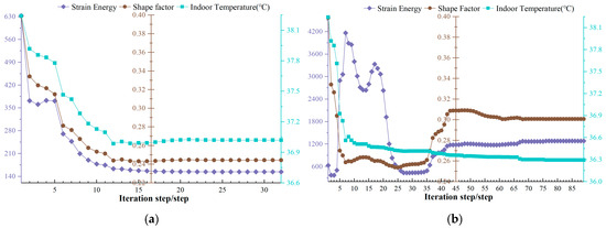
Figure 9.
Indoor Temperature & Shape Factor & Strain Energy: (a) Strain Energy Optimization; (b) Thermal Performance Optimization.
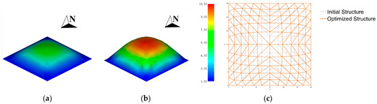
Figure 10.
Initial and optimized structure: (a) Initial structure; (b) Optimized structure; (c) Structural framework.
A strong correlation exists between the reduction in strain energy and the improvement of the thermal environment. During the optimization process, as the strain energy decreased, the structural volume increased at a faster rate than the surface area, resulting in a reduced surface-to-volume ratio and a corresponding decrease in the shape factor. The thermal density (TD) dropped from an initial value of 0.0152 to 0.0071—a reduction of 53.29%-and the indoor temperature also exhibited a decreasing trend. In the convergence phase of the optimization, a slight rebound in indoor temperature at the scale of 0.01 °C was observed, likely due to minor adjustments in the local surface morphology aimed at improving mechanical performance. However, the overall trend still indicates a positive correlation between strain energy reduction and indoor temperature decline. The strain energy optimization strategy not only effectively improved the structural mechanical performance but also indirectly contributed to indoor thermal improvement. However, since the optimized form did not develop self-shadowing features, the cooling effect was relatively limited compared to direct optimization for indoor temperature minimization. This highlights the efficiency boundary of indirect optimization approaches.
In exclusive thermal optimization, the indoor temperature is significantly reduced, but structural stiffness decreases considerably, which may compromise structural safety and stability. In contrast, exclusive strain energy optimization leads to a notable enhancement in structural rigidity, while improvements in thermal performance remain relatively limited. Relying solely on single-objective optimization strategies can result in performance imbalances. Therefore, strain energy plays an essential role in the optimization process and should not be neglected. When strain energy minimization is set as the optimization objective, a correlation between strain energy reduction and thermal environment improvement is observed. The optimized structures achieve maximum height, with volume increasing at a faster rate than surface area, resulting in a reduced surface-to-volume ratio. This morphological evolution pattern closely resembles that obtained under thermal-performance-driven optimization, indicating an intrinsic relationship between mechanical performance and thermal environmental performance. To achieve more efficient and reliable design outcomes, it is crucial to establish a collaborative optimization framework that integrates thermal performance and structural strain energy. This approach ensures structural safety while improving indoor thermal conditions, ultimately achieving a balanced and optimal multi-objective design.
3.3. Integrated Optimization of Thermal and Structural Performance
To identify a rational optimization strategy that balances thermal performance and structural strain energy, different proportions of strain energy (represented by weighting coefficients α) were introduced into the original thermal-performance-driven objective. The influence of combined thermal and structural considerations on surface morphology was investigated. The optimized strain energy, indoor temperature, shape factor, and morphological diagrams are summarized in Table 3. When α = 0, the objective function is entirely dominated by thermal performance. In this case, the indoor temperature decreases by 1.95 °C after optimization, while the strain energy increases by 102.83%. As α increases (α > 0), the strain energy decreases, and the indoor temperature also drops to varying degrees. Concurrently, the shape factor stabilizes, indicating a more compact structural geometry with reduced surface area per unit volume. The solar exposure rate (SER) also decreases accordingly.
Table 3.
Optimized Strain Energy, Indoor Temperature, Shape Factor, and Morphological Diagrams for Different α Values.
The optimized structural morphology also reveals that, as α increases, the structure evolves from an initial form characterized by a dome-like uplift in the central region and four upward-extending ridges along the diagonal directions of the plane, into a paraboloid shape. The original saddle-shaped surface with alternating peak–valley patterns and self-shadowing features gradually transitions into a smoother parabolic form. When α = 1, the objective function is entirely dominated by strain energy. The resulting surface morphology becomes a simple and symmetric paraboloid. In this case, the mesh density decreases in the central region while increasing near the supports, thereby enhancing local stiffness around the support areas. The shape factor reaches its minimum value, indicating that the structural form achieves a favorable balance between thermal performance and mechanical performance.
As this study focuses only on scenarios where strain energy is increased (ignoring cases where the post-optimization variation rate is >0%), the variation rates of strain energy and indoor temperature are shown in Figure 11. In the collaborative optimization analysis of thermal performance and structural mechanics, the optimization process was divided into three characteristic intervals based on the gradient of the weighting coefficient α (ranging from 0 to 1.0): Thermal-Dominated Zone (α ≤ 0.1), Balanced Zone (0.2 ≤ α ≤ 0.8), and Strain Energy-Dominated Zone (α ≥ 0.9). In the thermal-dominated zone, the optimization primarily improved thermal performance, with indoor temperatures reduced to 36.29 °C and 36.43 °C, respectively. However, the strain energy increased by more than double compared to the initial model, making these solutions impractical and therefore excluded from further consideration. In the balanced zone, although the magnitudes of the strain energy variation rate (%) and indoor temperature variation rate (‰) differ, both factors have comparable influence on structural behavior. Considering optimization effectiveness, different acceptable thresholds were defined: a strain energy variation rate greater than 45%, corresponding to an indoor temperature variation rate greater than 45‰. In the strain energy-dominated zone, the optimization significantly enhanced structural stiffness. The indoor temperature slightly increased compared to the balanced zone but remained lower than the initial value, with reductions ranging from 1.27 °C to 1.22 °C. Multiple feasible solutions that balance thermal performance and strain energy were obtained when α = 0.5, 0.6, 0.7, 0.9, 1.0. These configurations achieve effective thermal improvement while ensuring structural rigidity, representing a favorable trade-off between strain energy and indoor temperature.
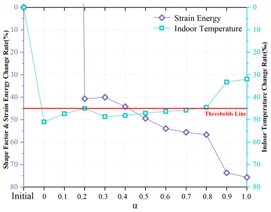
Figure 11.
Variation Rates of Strain Energy and Indoor Temperature after Optimization with Different α Values.
The mechanical performance of the feasible solutions (α = 0.5, 0.6, 0.7, 0.9, 1.0) was further evaluated, as summarized in Table 4. Results show that within the balanced zone (i.e., α = 0.5, 0.6, 0.7), the strain energy reduction ranged from 49.42% to 55.61%, while the decrease in base frequency varied from 26.11% to 32.21%. The elastic ultimate bearing capacity increased by 27.64% to 95.88%, and the elastoplastic ultimate bearing capacity improved by 44.68% to 55.91%. In the strain energy-dominated zone, when α = 0.9, the strain energy reduction reached 73.62% to 75.68%. The base frequency increased by 15.84% to 22.57%, and both the elastic and elastoplastic ultimate bearing capacities showed significant improvements—rising by 272.81% to 424.22% and 75.57% to 107.17%, respectively. The elastic ultimate bearing capacity was calculated using the buckling coefficient , whereas the elastoplastic ultimate bearing capacity was calculated using the consistent mode imperfection method with an initial geometric imperfection of L/300. The load–displacement curves were traced using the arc-length method [11,25] (Figure 12).
Table 4.
Optimized Structures Strain Energy, Indoor Temperature, Shape Factor, and Morphological Diagrams for Different α Values.
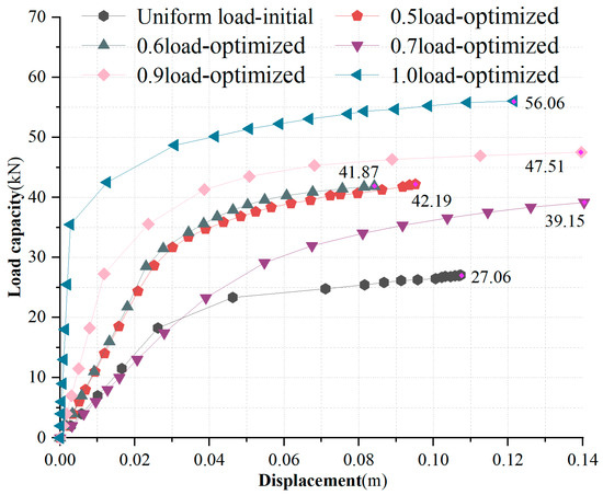
Figure 12.
Elastoplastic Load–Displacement Curves of the Initial and Feasible Optimized Structures.
The design of long-span roofs based on the collaborative optimization of strain energy and indoor temperature allows for differentiated strategies according to varying functional requirements. For static-load-dominant buildings such as industrial workshops and warehouses, it is recommended to adopt optimization schemes from the balanced zone, where both strain energy and indoor temperature are considered in the design process. Appropriate weighting coefficients include α = 0.5, 0.6, 0.7. By maintaining a relatively shallow depression along the east–west direction and a more pronounced one along the north–south axis, this geometric configuration enhances structural stiffness and stability bearing capacity while effectively reducing indoor temperature, thereby achieving energy-saving performance. In contrast, for dynamic-load-sensitive buildings such as theaters and stadiums, optimization schemes from the strain energy-dominated zone are advised. In these cases, greater emphasis should be placed on strain energy reduction, with weighting coefficients set at α = 0.9, 1.0. This approach not only significantly improves structural stiffness and stability bearing capacity but also notably increases the base frequency, effectively mitigating resonance risks caused by wind-induced vibrations or crowd activities. Both types of optimization schemes contribute to the improvement of structural load-transmission paths. The balanced-zone strategy emphasizes the synergistic optimization of thermal environment and static mechanical performance, whereas the strain-energy-dominated strategy focuses on enhancing dynamic structural response. These approaches provide a scientifically grounded basis for the design of long-span roof structures tailored to different building types.
4. Conclusions
To address the integrated design requirements of aesthetic expression, structural efficiency, and thermal performance in free-form grid structures, an optimization-based morphogenesis approach was developed. In this approach, the coordinates of shape-controlling nodes were defined as design variables. Three distinct optimization strategies were explored: ① by setting thermal performance as the primary objective and subsequently analyzing the resulting mechanical behavior of the optimized configuration; ② by minimizing structural strain energy and evaluating the associated thermal performance of the resulting form; ③ by establishing a collaborative optimization framework that integrates both thermal and mechanical performance. In this framework, indoor temperature and strain energy were simultaneously optimized, with a dynamic proportional adjustment factor introduced to automatically balance the influence of objectives with different dimensions through an implicit dimensionless normalization method. This mechanism prevents dominance by any single objective and enables a comprehensive optimization of both structural performance and indoor thermal environment. The effectiveness of these strategies was validated through numerical examples.
As indicated by the validation results of numerical examples, under both extreme thermal loading conditions and long-term thermal loading conditions, the optimized roof structure exhibits a saddle-shaped surface with self-shadowing characteristics: a dome-like uplift in the central region, combined with four upward-extending ridges along the diagonal directions of the plane, forming an alternating peak–valley morphology. This geometric configuration effectively reduces the solar exposure rate of the structural surface, shape factor, and thermal density, thereby significantly lowering indoor temperatures during extreme heat events. However, the structural strain energy increases accordingly. Free-form optimization targeting strain energy minimization follows a similar morphological evolution pattern as that observed in thermal-performance-driven optimization, and also achieves indoor temperature reduction, indicating an intrinsic correlation between strain energy optimization and thermal environmental performance improvement. The multi-objective collaborative optimization outcomes were categorized into three distinct zones based on the weighting coefficient α: ① In the thermal-dominated zone, although indoor temperature is reduced, the strain energy increases significantly and structural stiffness decreases, making this zone unsuitable for practical applications. ② In the balanced zone, where α = 0.5, 0.6, 0.7, both structural stiffness and stability bearing capacity are enhanced. The strain energy is reduced by 49.42% to 55.61%, the elastic ultimate bearing capacity increases by 27.64% to 95.88%, and the elastoplastic ultimate bearing capacity improves by 44.68% to 55.91%. In this zone, the roof retains the peak–valley surface morphology consistent with that of the thermally optimized form. ③ In the strain energy-dominated zone (α = 0.9, 1.0), improvements in stiffness, natural frequency, and stability bearing capacity become even more pronounced. Strain energy is reduced by 73.62% to 75.68%, the natural frequency increases by 15.84% to 22.57%, the elastic ultimate bearing capacity rises by 272.81% to 424.22%, and the elastoplastic ultimate bearing capacity increases by 75.57% to 107.17%. The resulting roof geometry evolves into a simple, symmetric paraboloid, with a sparser structural layout at the center and a denser configuration near the supports, thereby enhancing local stiffness in those regions. In summary, the optimized solutions corresponding to α = 0.5, 0.6, 0.7, 0.9, 1.0 demonstrate strong engineering feasibility and can be flexibly applied to meet the design requirements of various building types.
For long-span industrial workshops and warehouses in hot–humid climates—typical static-load-dominant buildings—the design proportions from the balanced zone (α = 0.5, 0.6, 0.7) are recommended for roof optimization. This approach effectively improves structural stiffness, thermal performance, and stability bearing capacity while significantly reducing indoor temperature, thereby achieving energy-saving benefits. In contrast, for dynamic-load-sensitive buildings such as theaters and stadiums, it is advisable to adopt the optimization ratios from the strain energy-dominated zone (α = 0.9, 1.0). This strategy not only enhances thermal performance, structural stiffness, and stability bearing capacity, but also substantially increases the natural frequency, helping to mitigate resonance risks caused by wind-induced vibrations or human activities. Both optimization approaches contribute to the improvement of structural load-transmission paths. The balanced-zone strategy emphasizes the synergistic optimization of thermal environment and static mechanical performance, whereas the strain energy-dominated strategy focuses on enhancing multiple aspects of structural mechanics. These findings provide a scientific basis and practical reference for the optimized design of roofs in various types of long-span buildings.
A primary limitation of this work lies in its specific geographical and climatic context, having been tested solely under the extreme thermal conditions of Haikou. Future research should aim to extend this methodology by introducing a broader spectrum of thermal environments, including those representative of temperate zones, to enhance the robustness and general applicability of the optimization framework. Furthermore, integrating economic considerations and exploring the optimization of member cross-sections represent crucial steps towards practical engineering application.
Author Contributions
Conceptualization, Methodology, Supervision, and Funding acquisition, B.J.; Software, Data curation, Formal analysis, Visualization, and Writing—Original Draft, B.H.; Writing—Review & Editing, B.W. All authors have read and agreed to the published version of the manuscript.
Funding
This research was funded by the National Natural Science Foundation of China (NSFC, Grant No. 52468020 and 51968018).
Institutional Review Board Statement
Not applicable.
Informed Consent Statement
Not applicable.
Data Availability Statement
The data sets presented in this study are available within the article.
Acknowledgments
We wish to acknowledge the Editors and the insightful and constructive reviews of anonymous reviewers.
Conflicts of Interest
The authors declare that they have no known competing financial interests or personal relationships that could have appeared to influence the work reported in this paper.
References
- Liu, J.; Dong, L.; Sun, S. An Introduction to Green Buildings, 2nd ed.; China Architecture & Building Press: Beijing, China, 2020. [Google Scholar]
- Kociecki, M.; Adeli, H. Two-phase genetic algorithm for topology optimization of free-form steel space-frame roof structures with complex curvatures. Eng. Appl. Artif. Intell. 2014, 32, 218–227. [Google Scholar] [CrossRef]
- Zhao, Z.; Yu, D.; Zhang, T.; Gao, H. Form-finding and optimization for free form grid structures supported by branching columns based on updated force density method. Structures 2022, 44, 1190–1203. [Google Scholar] [CrossRef]
- Wang, Z.; Cao, Z.; Fan, F.; Sun, Y. Shape optimization of free-form grid structures based on the sensitivity hybrid multi-objective evolutionary algorithm. J. Build. Eng. 2021, 44, 102538. [Google Scholar] [CrossRef]
- Longarini, N.; Crespi, P.; Zucca, M. The influence of the geometrical features on the seismic response of historical churches reinforced by different cross lam roof-solutions. Bull. Earthq. Eng. 2022, 20, 6813–6852. [Google Scholar] [CrossRef]
- Cui, C.; Yan, H. A morphosis technique for curved-surface structures of arbitrary geometries—Height adjusting method and its engineering applications. China Civ. Eng. J. 2006, 39, 1–6. (In Chinese) [Google Scholar]
- Cui, C.; Wang, Y.; Jiang, B.; Cui, G. Study on the structural morphogenesis technique for single-layer reticulated shells of free-curved surface. China Civ. Eng. J. 2013, 46, 57–63. (In Chinese) [Google Scholar] [CrossRef]
- Yang, F.; Yu, T.; Liu, Z.; Bui, T.Q. Isogeometric double-objective shape optimization of free-form surface structures with Kirchhoff–Love shell theory. Finite Elem. Anal. Des. 2023, 223, 103989. [Google Scholar] [CrossRef]
- Yang, F.; Yu, T.; Hirshikesh; Bui, T.Q. Morphogenesis of free-form surface structures based on geometrically nonlinear isogeometric analysis. Eng. Anal. Bound. Elem. 2024, 164, 105759. [Google Scholar] [CrossRef]
- Venuti, F.; Bruno, L. Influence of in-plane and out-of-plane stiffness on the stability of free-edge gridshells: A parametric analysis. Thin Walled Struct. 2018, 131, 755–768. [Google Scholar] [CrossRef]
- Lu, M.F.; Ye, J.H. Static stability research on single-layer spherical shells based on form vulnerability theory. Eng. Mech. 2017, 34, 76–84. (In Chinese) [Google Scholar]
- Ariyanayagam, A.; Mahendran, M. Influence of cavity insulation on the fire resistance of light gauge steel framed walls. Constr. Build. Mater. 2019, 203, 687–710. [Google Scholar] [CrossRef]
- Chen, W.; Jiang, J.; Ye, J.; Zhao, Q.; Liu, K.; Xu, C. Thermal behavior of external-insulated cold-formed steel non-load-bearing walls exposed to different fire conditions. Structures 2020, 25, 631–645. [Google Scholar] [CrossRef]
- Anand, J.; Sailor, D.J.; Baniassadi, A. The relative role of solar reflectance and thermal emittance for passive daytime radiative cooling technologies applied to rooftops. Sustain. Cities Soc. 2021, 65, 102612. [Google Scholar] [CrossRef]
- Bizjak, M.; Žalik, B.; Lukač, N. Evolutionary-driven search for solar building models using LiDAR data. Energy Build. 2015, 92, 195–203. [Google Scholar] [CrossRef]
- Zhang, R. Shape Design Parameters Study of Multilayer Office Building with Low Energy Consumption in Severe Cold Region Based on Digital Simulation. Master’s Thesis, Harbin Institute of Technology, Harbin, China, 2014. [Google Scholar]
- Feng, L.; Yang, S.; Zhou, Y.; Sun, J. Optimization strategy of architectural forms to improve the thermal comfort of residential area. J. Build. Eng. 2024, 86, 108905. [Google Scholar] [CrossRef]
- Pieskä, H.; Wang, C.; Nourozi, B.; Ploskić, A.; Wang, Q. Thermodynamic and thermal comfort performance evaluation of two geothermal high-temperature cooling systems in the mediterranean climate. J. Build. Eng. 2022, 56, 104738. [Google Scholar] [CrossRef]
- Ma, H. Study on the Optimal Design of Free-Form High-Rise Office Buildings Based on Radiation Heat Gain. Master’s Thesis, Harbin Institute of Technology, Harbin, China, 2018. [Google Scholar]
- Tang, R.; Meir, I.A.; Etzion, Y. Thermal behavior of buildings with curved roofs as compared with flat roofs. Sol. Energy 2003, 74, 273–286. [Google Scholar] [CrossRef]
- JGJ 26–2018; Design Standard for Energy Efficiency of Residential Buildings in Severe Cold and Cold Regions. China Architecture & Building Press: Beijing, China, 2018.
- ISO 52016-1; Energy Needs for Heating and Cooling, Internal Temperatures and Sensible and Latent Heat Loads. International Organization for Standardization: Geneva, Switzerland, 2017.
- Jiang, B.; Zhang, J.; Ohsaki, M. Shape optimization of free-form shell structures combining static and dynamic behaviors. Structures 2021, 29, 1791–1807. [Google Scholar] [CrossRef]
- Piegl, L.; Tiller, W. The NURBS Book, 2nd ed.; Springer: Berlin, Germany, 1997. [Google Scholar]
- Shen, S.; Zhi, X. Failure mechanism of reticular shells subjected to dynamic actions. China Civ. Eng. J. 2005, 38, 11–20. (In Chinese) [Google Scholar]


Disclaimer/Publisher’s Note: The statements, opinions and data contained in all publications are solely those of the individual author(s) and contributor(s) and not of MDPI and/or the editor(s). MDPI and/or the editor(s) disclaim responsibility for any injury to people or property resulting from any ideas, methods, instructions or products referred to in the content. |
© 2025 by the authors. Licensee MDPI, Basel, Switzerland. This article is an open access article distributed under the terms and conditions of the Creative Commons Attribution (CC BY) license (https://creativecommons.org/licenses/by/4.0/).