Technical Note

HUB3D: Intelligent Manufacturing HUB System

by
Antonio Trejo-Morales
*,
Edgar Adrián Franco-Urquiza
,
Hansell David Devilet-Castellanos
and
Dario Bringas-Posadas
Centro de Ingeniería y Desarrollo Industrial, Av. Playa Pie de la Cuesta No. 702, Desarrollo San Pablo, Santiago de Querétaro 76125, Querétaro, Mexico
*
Author to whom correspondence should be addressed.
Technologies 2024, 12(7), 109; https://doi.org/10.3390/technologies12070109
Submission received: 23 May 2024 / Revised: 2 July 2024 / Accepted: 5 July 2024 / Published: 9 July 2024
(This article belongs to the Special Issue 3D Printing Technologies II)

Abstract

:
HUB3D represents a cutting-edge solution for managing and operating a 3D printer farm through the integration of advanced hardware and software. It features intuitive, responsive interfaces that support seamless interaction across various devices. Leveraging cloud services ensures the system’s stability, security, and scalability, enabling users from diverse locations to effortlessly upload and manage their 3D printing projects. The hardware component includes a purpose-built rack capable of housing up to four 3D printers, each synchronized and managed by a manipulator arm controlled via Raspberry Pi technology. This setup facilitates continuous operation and high automation, optimizing production efficiency and reducing downtime significantly. This integrated approach positions HUB3D at the forefront of additive manufacturing management. By combining robust hardware capabilities with sophisticated software functionalities and cloud integration, the system offers unparalleled advantages. It supports continuous manufacturing processes, enhances workflow efficiency, and enables remote monitoring and management of printing operations. Overall, HUB3D’s innovative design and comprehensive features cater to both individual users and businesses seeking to streamline 3D printing workflows. With scalability, automation, and remote accessibility at its core, HUB3D represents a pivotal advancement in modern manufacturing technology, promising increased productivity and operational flexibility in the realm of additive manufacturing.

1. Introduction

The field of additive manufacturing is experiencing accelerated growth due to the numerous advantages it offers for rapid prototyping and design validation. Despite this, additive manufacturing has the potential to integrate components for industrial use in various sectors worldwide. The main challenges are the high costs associated with the technology and materials used. The Center for Engineering and Industrial Development (CIDESI), has the necessary technology to supply both local and international markets, working with metal alloys, polymers, and developing new compounds. Mexico is not usually considered a technology provider according to international analysts, but rather a potential customer.
Currently, CIDESI has several additive manufacturing printers operated by a highly specialized team in this field. As a research and development center, there is a need to create prototypes or unique components using a wide range of materials. However, the process of requesting the manufacture of these components is often slow due to multiple intermediaries before their execution. CIDESI has the potential, infrastructure, and expertise to establish an additive manufacturing center focused on polymeric and metallic parts. This project aims to improve printer management by implementing a web interface, consolidating the dispersion of technologies and infrastructures. This platform provides real-time data on the status of the printer in use, including information such as temperatures, uploaded files, and other relevant parameters. Additionally, it facilitates file uploading and remote printing job submission, enabling real-time monitoring of printing progress and greater intervention in the process. This effort is aimed at optimizing any 3D printing process in our facilities. Our goal is to achieve this efficiency through internal knowledge generation, the development of proprietary technology, and collaboration with third-party knowledge and technologies. All of this is carried out using the human and financial resources available at the center.
In recent years, the technologies of great interest that have been implemented include stereolithography (SLA), which began in 1984, and is an additive manufacturing process that works by focusing an ultraviolet (UV) laser on a vat of photopolymer resin [1]; laminate object manufacturing (LOM) in 1985, which is a rapid prototyping system where layers of paper coated with adhesive, plastic, or metallic laminates are successively glued together and cut to shape them [2]; by 1986, solid ground curing (SGC), which utilizes the general process of photopolymer hardening through complete illumination and hardening of the entire surface [3]; in 1987, selective laser sintering (SLS), which involves depositing a layer of powder a few tenths of a millimeter thick into a vat heated to a temperature slightly below the powder’s melting point, approximately one degree [4]; later, in 1989, fused deposition modeling (FDM), which is based on three main elements: a printing bed/plate where the piece is printed, a filament spool that serves as the printing material, and an extrusion head also called an extruder; and lastly, from 1985 to the present, 3D concrete printing (3DCP), which refers to various technologies that use 3D printing as the central method for manufacturing buildings or construction components [5].
According to the above, different software platforms have emerged for controlling various 3D printing technologies, such as OctoPrint [6], an open-source and free application for controlling 3D printers. It allows for remote management of prints and full control over the print queue with ease. Printrun [7], on the other hand, is a comprehensive set of host interfaces for 3D printers and CNC machines, consisting of Pronterface as a GUI host, Pronsole as an interactive command line host, and Printcore as an API that facilitates communication with RepRap [8]. In the field of digital manufacturing, 3D printing has emerged as a revolutionary technology, enabling the creation of prototypes and final parts quickly and efficiently. However, as production needs scale, the need arises to develop 3D printing systems that are not only commercially scalable, but also offer flexibility in terms of control and operation.
At present, 3D printing systems on the market present significant limitations in terms of scalability and flexibility; our solution stands out for its adaptability to both industrial and domestic environments, its scalability that allows it to grow with user needs, and its multi-platform compatibility, ensuring a seamless experience. Furthermore, its readable source code facilitates customization according to specific needs, thus offering efficient and versatile management for 3D printing farms, surpassing the limitations of other alternatives available in the market. Most of these systems are designed to operate in specific environments, either through programmable logic controllers (PLC) for automated industrial applications or through manual configurations for simpler environments. However, there is no integrated solution that combines both approaches, allowing for an easy transition between automated and manual operations according to the user’s needs.
This technical note is divided into several sections. In Section 1, we provide information about the theoretical basis. In Section 2, we describe the materials and methods used in the development system. In Section 3, we present the results. Section 4 discusses future research directions. In Section 5, a conclusion is presented. Finally, we list the references that support this work.

Theoretical Basis

This chapter aims to provide a solid theoretical basis for the development of the proposed scalable and flexible 3D printing system. The main theories, concepts, and previous studies that support the relevance and viability of the project will be explored. The theoretical framework is essential to contextualize the research problem, establish key variables and justify the methodological decisions taken. Three-dimensional printing has transformed numerous industrial sectors, offering an efficient and economical alternative for the production of prototypes and final parts. However, scalability and operational flexibility remain significant challenges. The existing literature has addressed various solutions, but few have effectively integrated automated control systems, such as PLCs, with manual operation options.
Several studies have highlighted the relevance of scalability in 3D printing for commercial applications, emphasizing that the ability to increase production without compromising quality is crucial to achieving success in highly competitive markets [9]. PLCs are widely used in industrial automation due to their robustness and versatility. Integrating PLCs into 3D printing systems can significantly improve the efficiency and accuracy of operations [10]. The flexibility to operate in both automated and manual mode is essential to adapt to various needs and production environments.
Recent studies have explored hybrid configurations, but practical implementation still presents challenges [11]. Existing technologies are detailed below: (a) Technological scalability is based on the idea that modular systems are essential for seamless growth in production. These systems allow flexible and adaptive adjustments as market demands evolve, minimizing downtime and optimizing available resources [12]. (b) The hierarchical control model of automated systems provides a theoretical framework for understanding how PLCs can be effectively integrated into 3D printing systems. This allows structured and efficient management of operations, improving coordination and overall performance of the production system [13]. (c) The most common 3D printing systems are as follows:
  • Printoid [14]: A mobile application for controlling 3D printers from Android devices. It offers a limited free version with basic features and a paid version with advanced features like remote monitoring, multi-printer control, and notifications. Key features: intuitive interface, remote printer control, real-time notifications, support for multiple printers.
  • Replicape [15]: An open-source platform for 3D printer control. Most basic functionalities are free, but there might be premium paid features, especially for specific hardware. Key features: printer control, compatibility with various printer types, hardware integration, advanced control features.
  • AstroPrint [16]: A cloud-based platform for 3D printer management. It offers a free version with limited features and paid subscription plans that include advanced features like remote management, cloud storage, and print analytics. Key features: remote printer management, cloud storage, data analytics, compatibility with multiple devices.
  • 3DPrinterOS [17]: A cloud platform for 3D printer management and monitoring. It offers a free version with basic features and subscription plans for businesses with features like centralized management, data analytics, and advanced control. Key features: centralized printer management, data analytics, remote control, cloud services integration.
  • Ultimaker Digital Factory [18]: A 3D printing management platform developed by Ultimaker for their printers. It’s included as part of the Ultimaker ecosystem, although there might be premium features or subscription plans for additional functionalities like advanced analytics, automation, and workflow management. Key features: integrated printer management, workflow automation, advanced analytics, specialized technical support.

2. Materials and Methods

The materials listed in Table 1 are used for the process described in Figure 1. The methodology details the procedures and techniques that are used to develop the modular, scalable, and flexible software system that enables the management of three-dimensional prints. This overall process ensures that the system meets the expected functional and performance requirements, allowing it to be used in both automated industrial environments and manual applications.
The development of the overall proposal allows for the creation of the software system in an efficient, effective, and structured way to achieve the expected result, summarized in the following steps:
  • Approach. In this initial phase, the problem is defined clearly. Key issues, challenges, and objectives are identified to ensure a focused direction for the project.
  • Requirements. In this phase, the specific needs and expectations of stakeholders are gathered and documented. This includes detailed descriptions of functionalities, performance criteria, and other essential elements necessary for the project’s success.
  • Iterations. This stage is a cyclical process of continuous refinement and improvement of project results, complemented by the following phases. Planning: Detailed plans are created describing the project schedule, resources, milestones, and risk management strategies. Design: In this phase, the project architecture and design specifications are developed. This includes creating use case diagrams, wireframes and rapid prototyping, and design mockups that provide a clear development model. Development: Code is typed, components are built, and integration is produced based on the design specifications. Testing: Unit tests are applied to identify and correct any problems or defects. To ensure the project meets the defined requirements and functions correctly before delivery.
  • Delivery. Finally, this phase involves the final handover of the project to the client or end-users. Comprehensive documentation, training, and support are provided to ensure a smooth transition and successful implementation.

3. Results

3.1. Approach

The Center for Engineering and Industrial Development (CIDESI) offers 3D printing services to its employees. To do so, users have to email print files and specifications to the additive manufacturing department, which generates significant administrative work. To improve efficiency and simplify access to these resources, CIDESI has decided to develop an additive manufacturing HUB to streamline the 3D printing service, reduce the dispersion of technologies by pooling infrastructure, enable data collection for market trend analysis, and into a future stage, enable the implementation of AI algorithms for preconditioning.
This initiative to develop a software platform will allow CIDESI‘s specialists to focus on achieving differentiation. This system is flexible and can expand its functionalities according to technological advances that emerge over time.

3.2. Requirements

The development of a progressive web application system is required which is primarily characterized by its efficiency and speed, is open-source, and is written in the JavaScript programming language. This development should be significantly inspired by OctoFarm, a free and open-source web interface that unifies instances of OctoPrint, to facilitate the monitoring of 3D printer farms. The software will have a high-level layer to effectively monitoring and control 3D printing processes locally and remotely; provide a cloud service that allows users from different geographic locations to make requests and submit their 3D printing models; and offer portability compatible with most mobile devices (tablets and phones). The main objective of the software system is to streamline the additive manufacturing process through a flexible, integrated hardware and software system.

3.3. Iteration

In this phase, work is carried out in short iterations called “sprints”. During each sprint, the development team focuses on completing a specific set of tasks (planning, design, development, and testing) and delivering a functional increment of the software. These tasks are detailed below:

3.3.1. Planning

Based on the problem statement, the software requirements, and a thorough analysis, it was possible to define in detail the following diagram (see Figure 2), which visually represents the workflows, the sequence of activities, and the modules that make up the software system. From this diagram, the backlog and the sprint required for the next task were derived.

3.3.2. Design

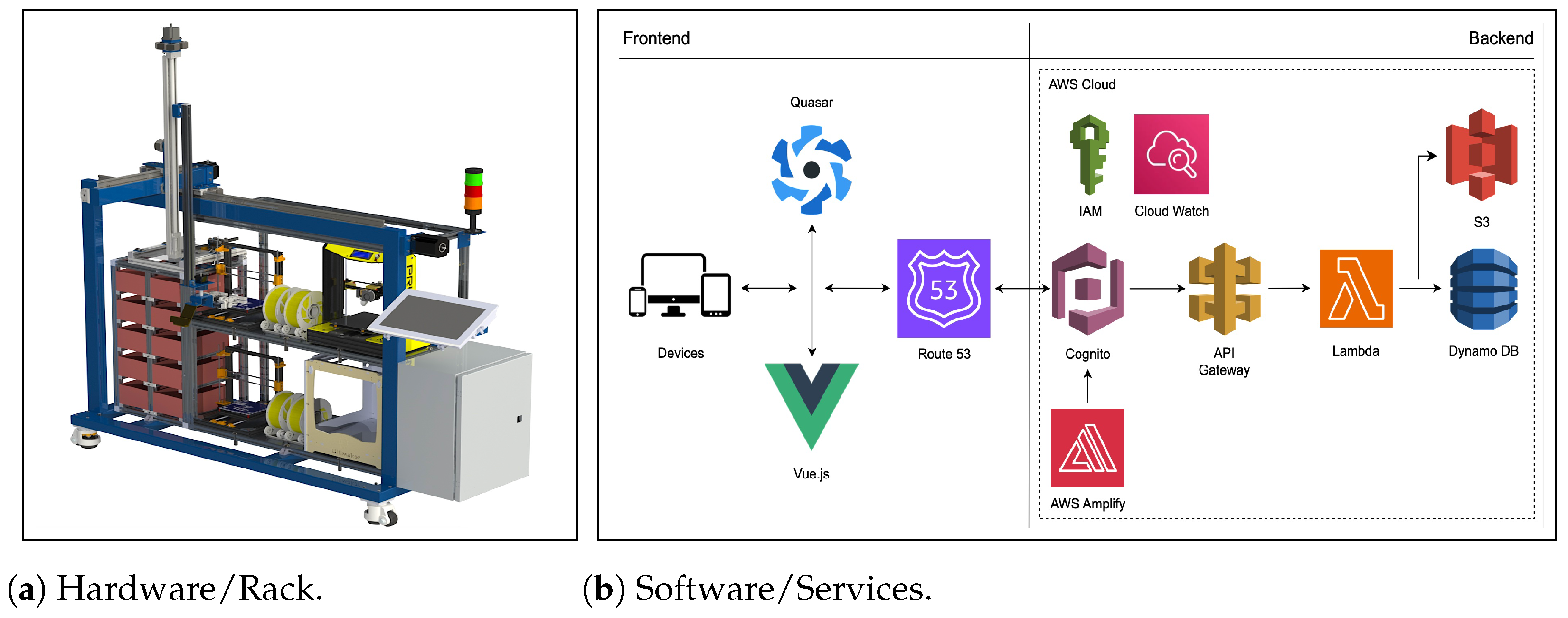
The hardware and software architecture is designed to transform the requirements in a software platform called HUB3D, as shown in the following Figure 3, to address an additive manufacturing HUB to enable the monitoring and control of three-dimensional prints. In addition, to collect data for the analysis of market trends. The above, for the generation of technology for the fourth industrial revolution (4IR).
(a)
Hardware architecture: This consists of a rack designed to house four 3D printers, which operate synchronously with a manipulator arm controlled by a programmable logic controller (PLC). It has compartments for storing finished parts. Additionally, it includes a Raspberry Pi electronic board with embedded OctoPi firmware [6], dedicated to receiving control instructions for 3D printers. This automated hardware version offers advanced features that allow for continuous manufacturing and 24/7 service operability (available 7 days a week and 24 h a day).
(b)
Software architecture: This details the components that integrate the system. It uses the Quasar and Vue.js frameworks for creating and configuring interactive and reactive user interfaces, reusable components, and support for multiple platforms. The services responsible for enabling the connection between the client user and the HUB3D operator are hosted on Amazon Web Services (AWS). This includes services like Route53 for establishing the domain; AWS Amplify and Cognito for managing user authentication; Lambda functions and API Gateway for linking to storage services in DynamoDB and S3 databases; also, IAM for managing user roles; Cloudwatch for monitoring instances stored in the cloud; and Serverless for serverless connection of the system in the cloud. Through an API and websocket systems, it is possible to connect to multiple 3D printers in a network, create a centralized management system (HUB) for the 3D printer farm to control, monitor, and upload additive manufacturing files (*.gcode) locally and remotely. It has a cloud service that allows users from different geographical locations to make requests and send their 3D printing models (*.stl file).
The design of the user interfaces (UI) has focused on the user experience (UX), with user-friendly interfaces (UI), which allow users (customers and operators) to be effective. The design is modular and facilitates the scalability and maintenance of the system. It consists of three main modules: Authentication, Customer, and Operator.

3.3.3. Development

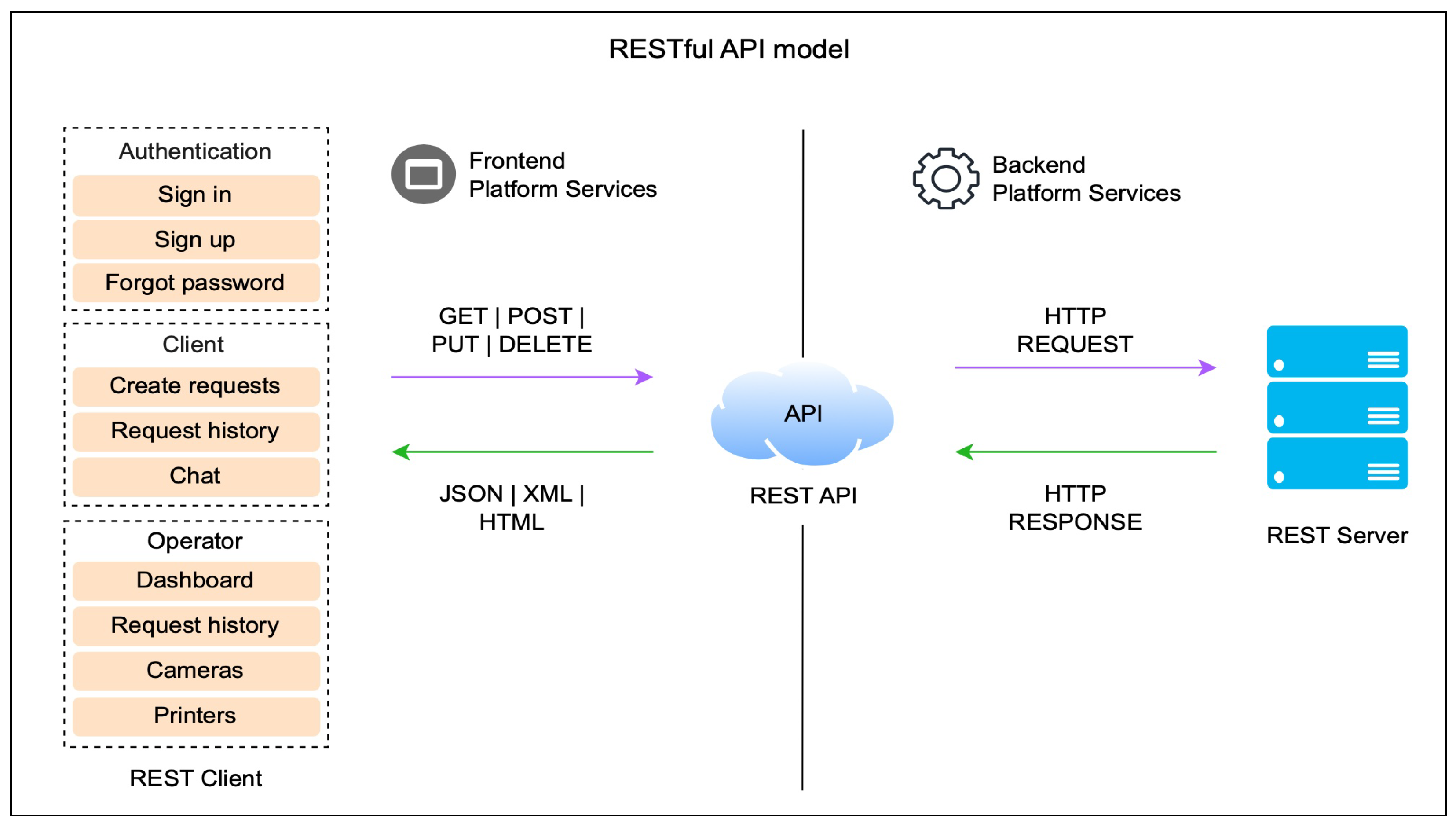
Here are the backend and frontend modules of the software application, as illustrated in Figure 4.
In the backend, two services are implemented to execute business logic and communication processes with the 3D printers:
(i)
AWS services. For the development and deployment of AWS services, the Serverless framework and Node.JS are used. The deployment file “*.yml” specifies the resources and functionality of the cloud infrastructure. These services allow for HTTP requests (see Figure 4), hosting of the PWA application, cloud file management, and authentication services, among others.
(ii)
Octoprint service. This hosts the orchestrator service of HUB3D, embedded in a Raspberry Pi, and through HTTP and WebSocket requests, allows for the controlling of print requests. It uses serial/USB and Ethernet/WiFi communication protocols.
In the frontend, user logic is executed, focusing on scalability and security to offer services such as user authentication, 3D printing requests through a form that allows attaching the file/model to be printed, a chat service enabling direct communication between the manufacturer and the customer, and options for local and remote monitoring and control (see Figure 4). The frontend leverages modern software technologies and cloud services to provide an efficient and automated solution for part manufacturing:
(i)
Authentication. This module manages and controls authorized access to the application’s resources through verification and validation. It provides users with the ability to securely log in by verifying credentials, facilitates the creation of new user accounts, and has a secure password recovery process.
(ii)
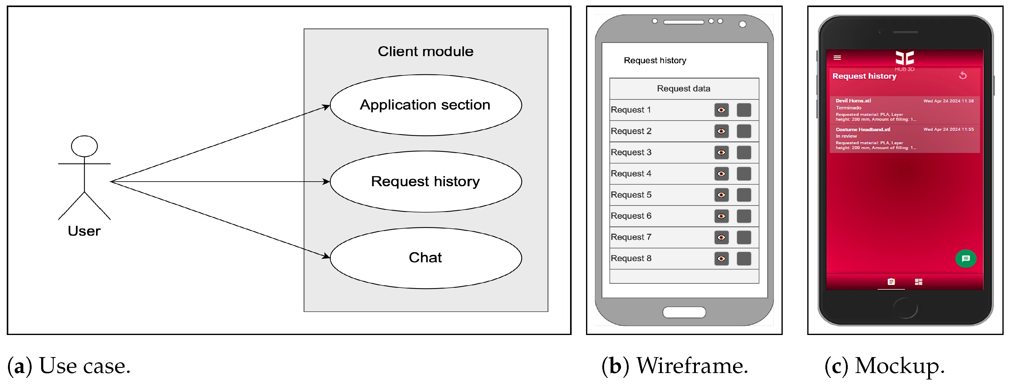
Client. The client module allows for the creation and tracking of 3D printing requests. Through an intuitive user interface, the client can submit new printing requests, access and track the status of requests in history, access a help chat for resolving any doubts or issues that may arise during the manufacturing process.
(iii)
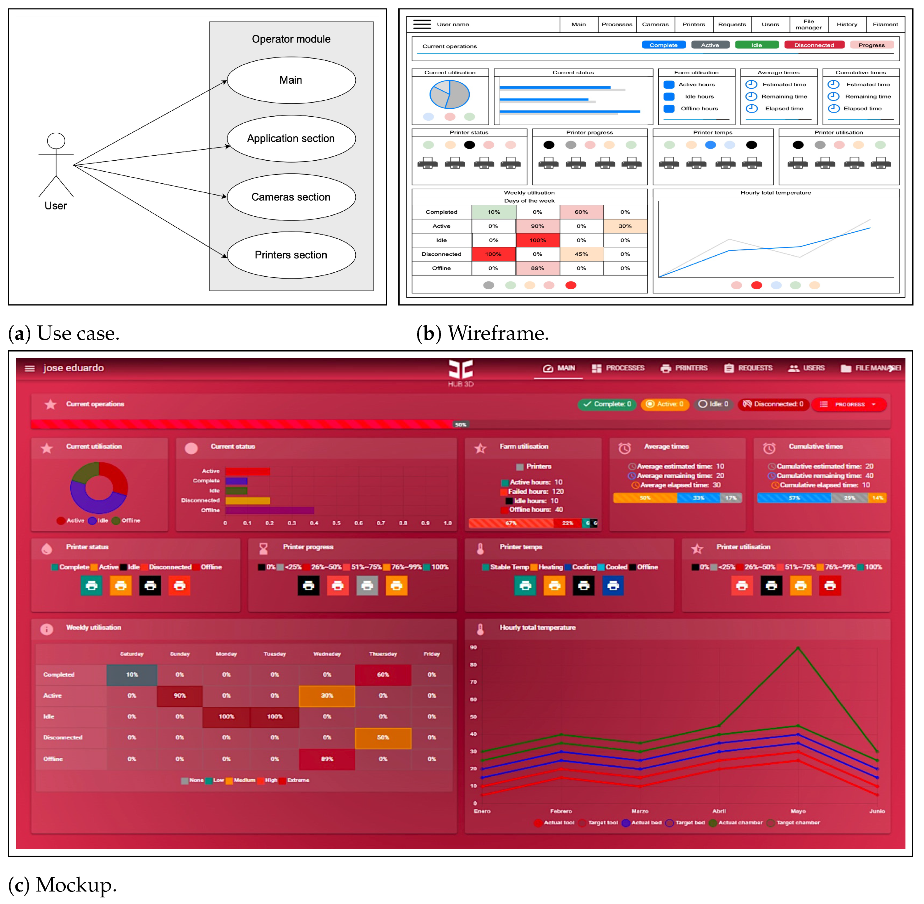
Operator. The operator module enables the effective and secure operation of the additive manufacturing process. It allows for processing and downloading of files, changing the status of requests, implements control commands to start, pause, and stop 3D prints, enables constant monitoring of manufacturing progress through cameras, receives notifications about important events, and provides access to the chat for conversation with client users.
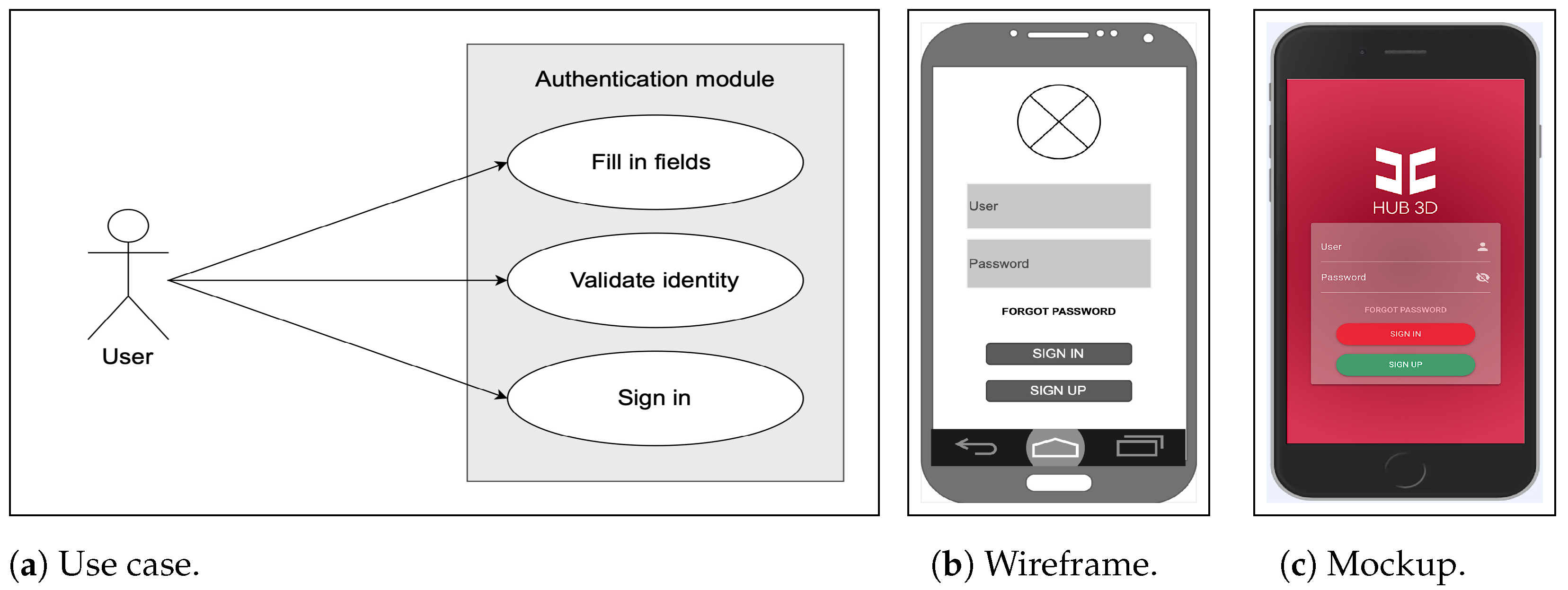
In the authentication module, user credentials are entered to access the HUB3D software platform. Figure 5 shows the details of the authentication module. This graphical user interface is displayed when users access the system’s URL through a web browser.
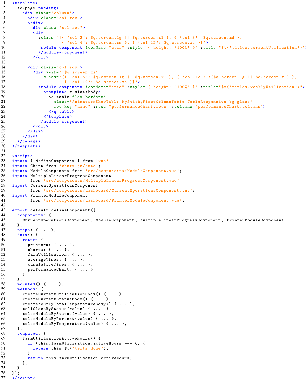
In the following code snippet Listing 1, the main methods and functions that make up the authentication module are described in a general manner. The methods are based on the Vue.js lifecycle and the Quasar framework. The data(): defines the data and states of the authentication component (auth); methods: define the methods and business logic; mounted(): is executed after the component is mounted on the DOM, in this case, it is used to initialize the username and password fields with default values; computed: defines the computed properties of the component. In this case, validateForm checks that the authentication form is complete, verifying if a username and password have been entered. The signIn() method performs user authentication using the input data (username and password) through the AWS authentication service (this.$Auth). If authentication is successful, the authentication token is stored in the browser’s local storage (localStorage) along with other user data. If an error occurs during the authentication process, it is handled in the catch block and a notification message is displayed.
Listing 1. Authentication module code snippet.
Technologies 12 00109 i001
To the client module, registered users on the HUB3D platform with the client role will be able to use this module. This graphical user interface is displayed when users access the system’s url through a web browser, as detailed below (see Figure 6).
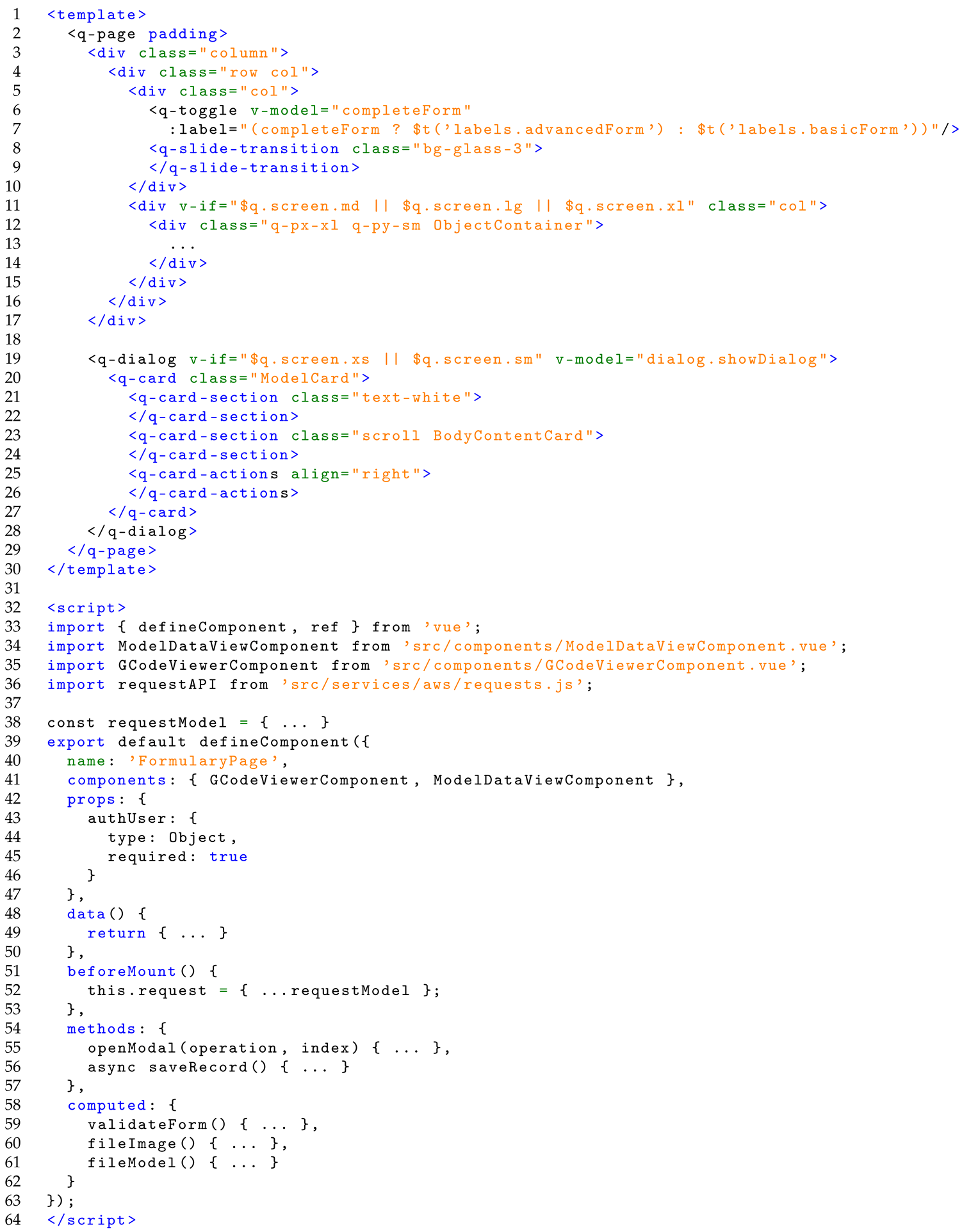
The following code snippet Listing 2, refers to the backend and frontend of the client module. This code implements the business logic that allows users to view all previously made requests in the manufacturing HUB3D; it allows listing the details of each request, including the attached files. Below are the main methods and functions that make up the client module based on the Vue.js lifecycle and Quasar framework. Components: imports the “GCodeViewerComponent” and “ModelDataViewComponent” components and makes them available; props: defines a property named “authUser” that is expected to be provided to the component and must be an object; data: defines the component’s data, including the request details, validation rules for form fields, available options for certain fields, dialog state, and complete form state; beforeMount: executed before the component is mounted on the DOM; methods: defines an openModal() method to open a dialog and a saveRecord() method to save a new request on the server; computed: defines computed properties of the component; validateForm checks if the form is valid, depending on whether it is complete or not, and fileImage and fileModel obtain the URLs of image and model files, respectively, for preview.
Listing 2. Client module code snippet.
Technologies 12 00109 i002
To the operator module, registered users on the HUB3D platform with the operator role can use multiple monitoring and control operations. Below is a detailed description of the operator module. This graphical user interface is displayed when users access the system’s URL through a web browser (see Figure 7).
The following code snippet Listing 3 refers to both the backend and frontend of the operator module. This code implements the business logic that allows operators to manage, operate, and interact with the manufacturing HUB3D through dialogs and sliders. Below are the main methods and functions that make up the operator module based on the Vue.js lifecycle and Quasar framework. Components: imports and registers the components used within the operator module; props: defines a property named “authUser” that is expected to be provided to the component and must be an object; data: defines the component’s data, including printer information, data for charts, 3D printer control information, average and cumulative times, and chart configuration; mounted: executed after the component is mounted on the DOM, where methods are invoked to create charts for current utilization, current status, and total hourly temperature; methods: defines methods to create charts and provides helper functions to assign classes and colors to printer modules and chart data; computed: defines computed properties of the component, in this case, it calculates the amount of active hours of the 3D printers and returns the text “Done” if there are no active hours.
Listing 3. Operator module code snippet.
Technologies 12 00109 i003

3.3.4. Testing

The tests performed on the system’s functionalities are subjected to rigorous unit tests to ensure their correct functioning and operational efficiency, guaranteeing execution as desired by the developer’s business logic/theory. These tests include performance, functionality, and usability tests, among others, to verify that the system meets the usability requirements and optimally satisfies the user’s needs. This analysis includes the execution time of scripts; the loading time of rendering resources, such as style files (*.css), JavaScript files (*.js), and images (*.png, *.jpeg, *.gif); the loading time of the painting task; the system time; the idle time. We also reviewed the interactions performed by the users on the GUI’s, looking at each HTTP request to the server and its respective response. The results show the efficiency of the requests and the response rates, identifying the bottlenecks that make the module slow. The results obtained allowed not only to optimize the overall performance of the system but also to improve its reliability and stability.
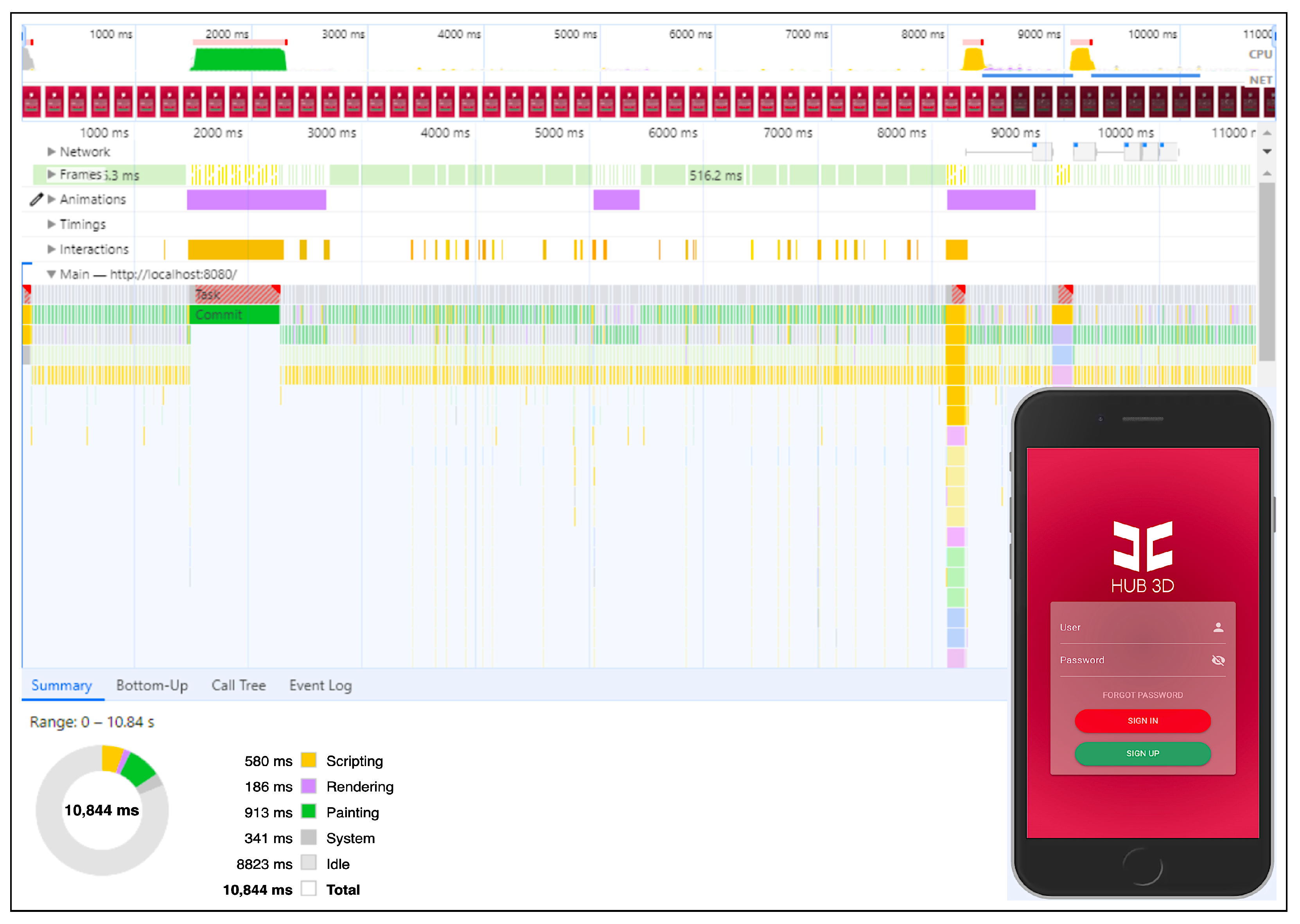
The results of testing the authentication module with the “Google Chrome DevTools” software tool are shown below. These tests ensure the user authentication process runs correctly and without errors, providing a secure and seamless user experience (see Figure 8).
The performance profiling data spans a total of approximately 11 s (10,844 ms) and provides detailed insights into the application’s performance during this period (see Table 2). The main observations are described below.
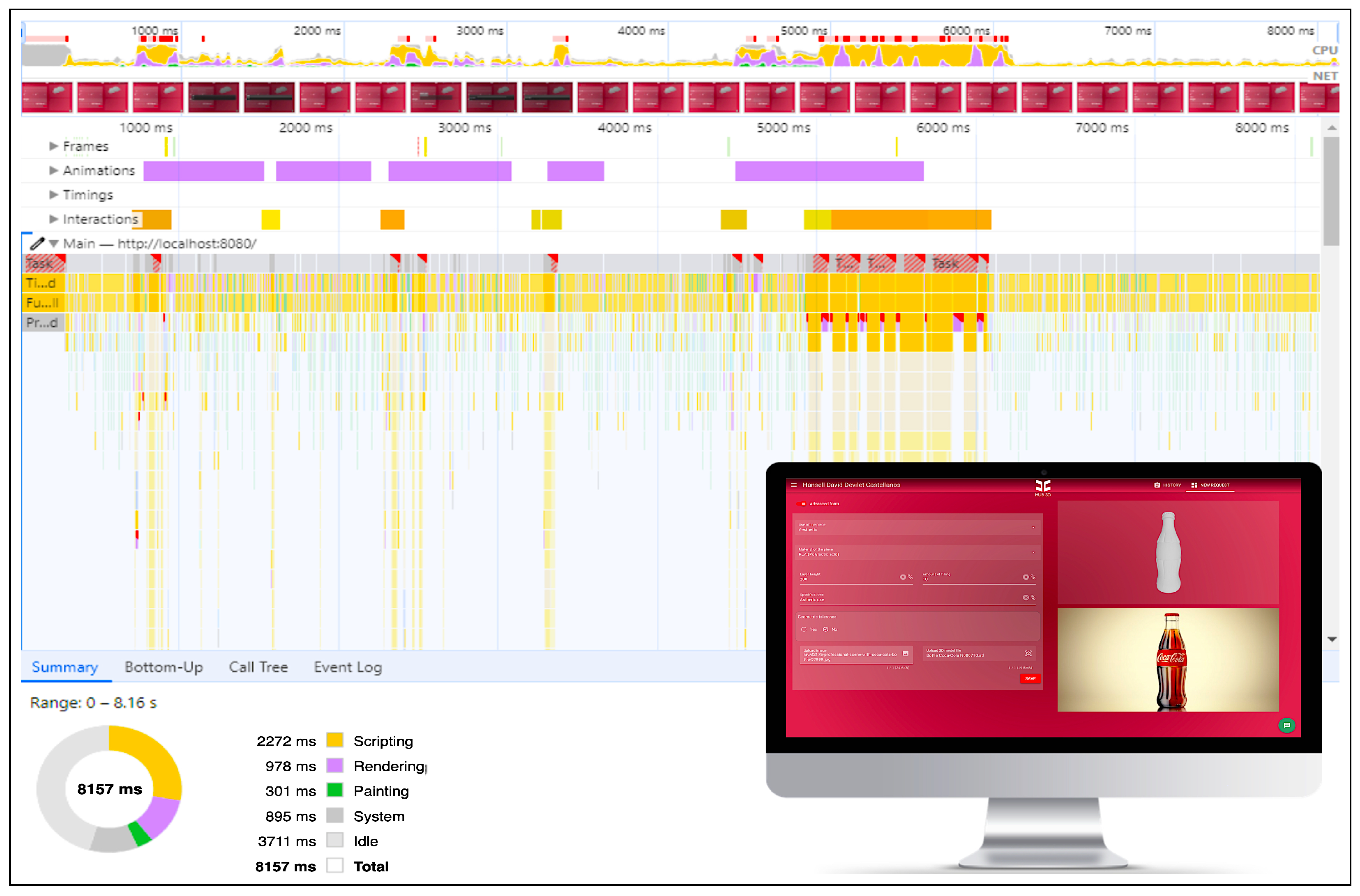
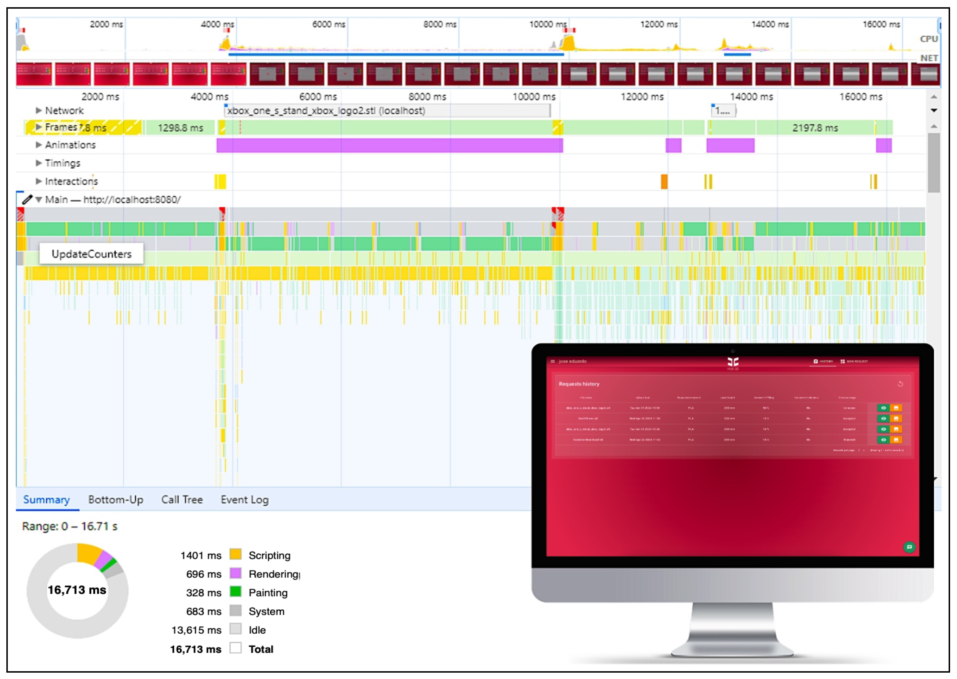
In the following Figure 9 and Figure 10, the result of performance testing of the client module with the “Google Chrome DevTools” software tool is shown. These tests are fundamental to ensure that the history and request processes run correctly and without errors, providing a secure and seamless user experience.
The performance profiling data spans a total of approximately 8 s (8157 ms) and provides detailed insights into the application’s performance during this period (see Table 3).
The performance profiling data span a total of approximately 17 s (16,713 ms) and provide detailed insights into the application’s performance during this period (see Table 4).
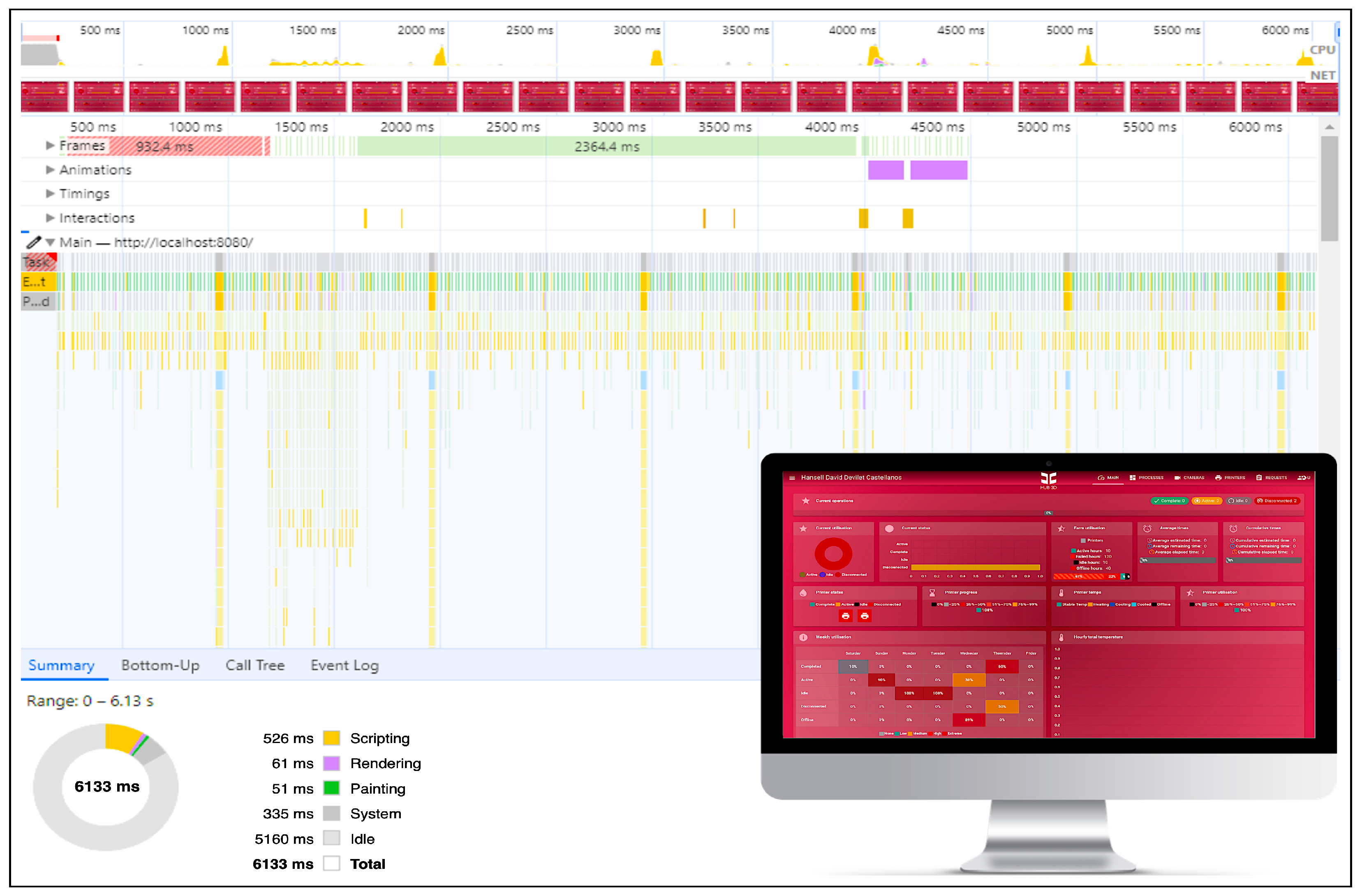
In the following Figure 11 and Figure 12, the result of performance testing of the operator’s main module with the “Google Chrome DevTools” software tool is shown. These tests are fundamental to ensure that the monitoring and control processes of the HUB3D run correctly and without errors, providing a secure and seamless user experience.
The performance profiling data spans a total of approximately 6 s (6133 ms) and provides detailed insights into the application’s performance during this period (see Table 5).
The performance profiling data span a total of approximately 44 s (43,758 ms) and provide detailed insights into the application’s performance during this period (see Table 6).
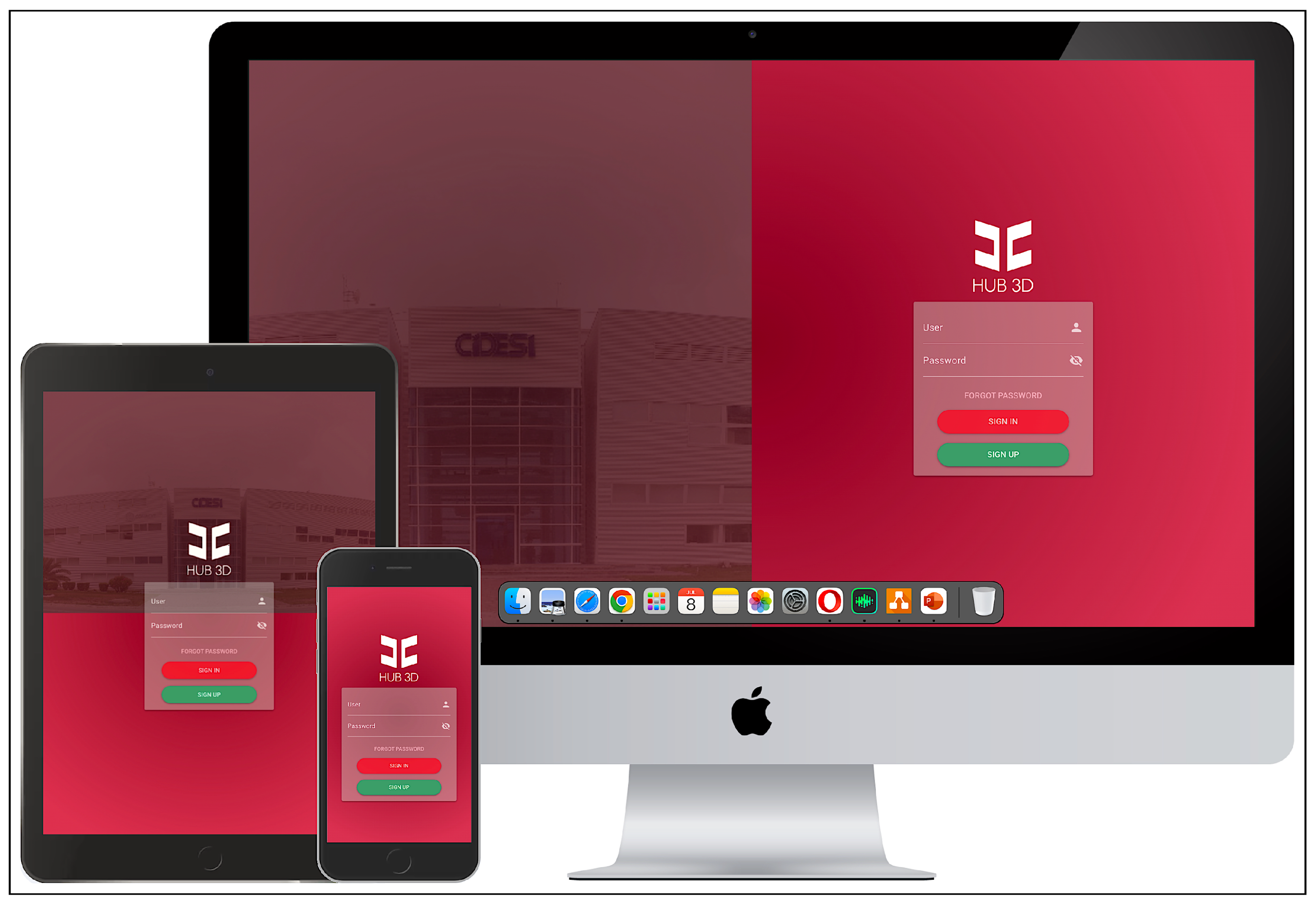
Additionally, to the performance tests of the HUB3D software system, it is also subjected to rigorous responsiveness tests to ensure its proper functioning on different devices and screen sizes. These tests were conducted to verify that the system is accessible and usable on mobile devices and desktop computers, meeting usability requirements and satisfying user needs. The results of these tests allowed for the identification and implementation of improvements, ensuring that functionalities remained intact without compromising performance across different devices.
Below are the results for different screens and devices on which responsiveness tests were conducted (see Figure 13). These tests and improvements ensure the user experience is consistent and effective regardless of the access medium. These tests included evaluations on smartphones, tablets, laptops, and desktop computers, aiming to identify and correct any display or functionality issues that might arise in each of these environments. Additionally, different browsers were considered to cover a wide range of possible scenarios and ensure the highest possible compatibility and performance.
Finally, a comprehensive speed test was performed to evaluate the overall performance of the computer system. This test is essential to ensure that all functionalities respond quickly and efficiently under various usage conditions. The results allowed us to identify potential areas for improvement and optimization, for software quality assurance, and to ensure that the system can handle high workloads without compromising the user experience. Below is an image illustrating the speed test performed, highlighting the response times and stability of the system (see Figure 14).
After optimization, the values obtained in the speed test of the progressive web application system are shown in Table 7. These results reflect solid system performance, fast response times, and a stable, smooth user experience. Low latency and high visual stability ensure that the system can effectively handle high usage demands without compromising the quality of the user experience. This test is crucial to know the speed of the system and its responsiveness in different conditions of use:

3.4. Delivery

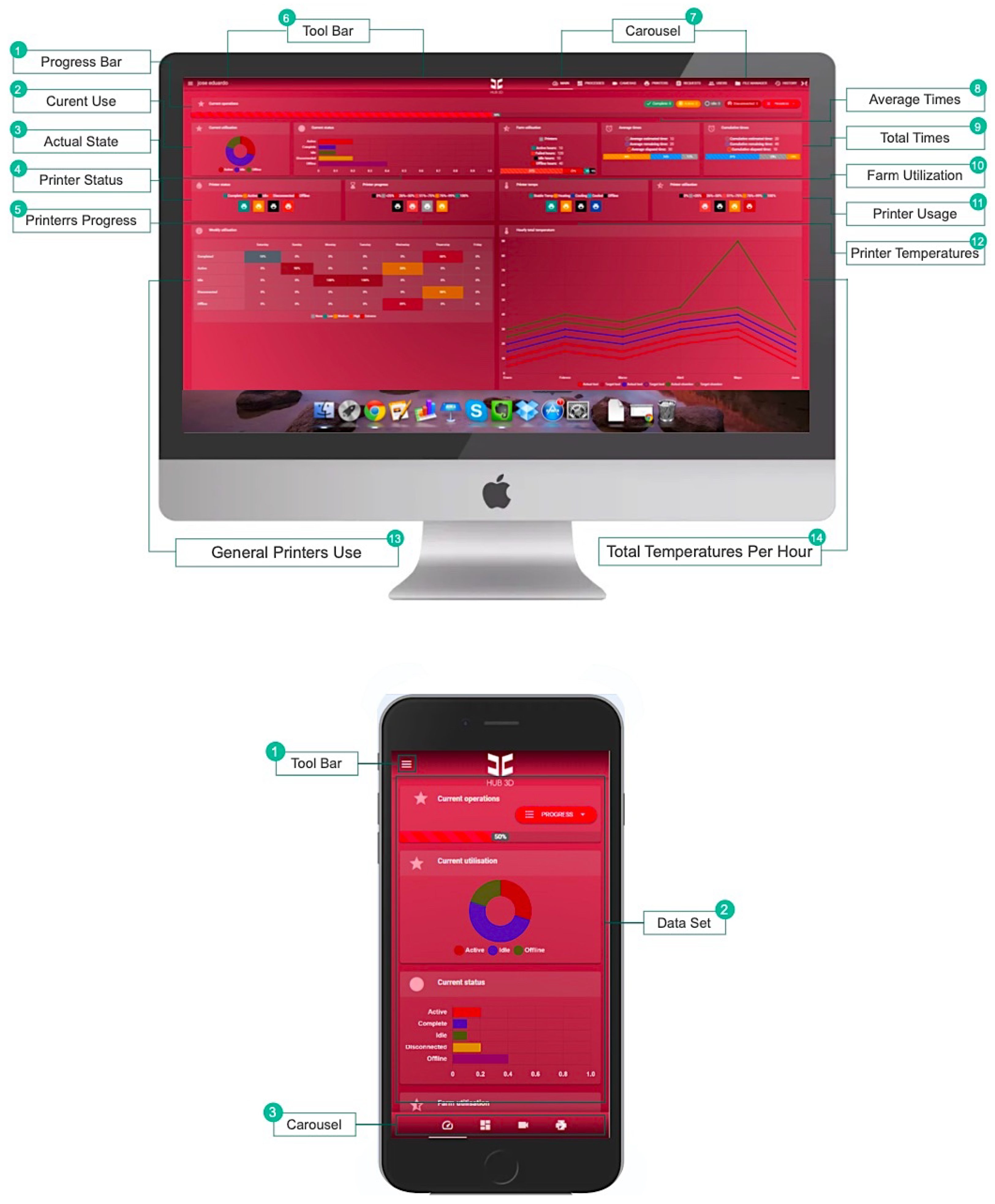
Below is an illustrative example showing the result of the main functionalities of the HUB3D software system (see Figure 15). And in the following link, you can watch an explanatory video: HUB3D Screencast (accessed on 2 July 2024).

4. Discussion

The implementation of a 3D printing HUB in CIDESI has proven to be a effective strategy to optimize management and access to 3D printing. The benefits in terms of efficiency, accessibility and management resources are significant, although they should be considered and managed challenges. This case serves as a model for other institutions and/or companies looking to improve their 3D printing services and reduce the associated administrative burden.
Therefore, for some years, the Center for Engineering and Industrial Development (CIDESI) has been offering 3D printing services to its employees, given that this service required users to send an email with their printing files and specifications to the engineering department, generating administrative management, in such a way as to improve the efficiency and facilitate access to these resources, CIDESI decides to implement a HUB to help streamline and streamline the 3D printing service, as this system type has the flexibility to increase its functionalities with based on technological developments over time.

5. Conclusions

The development and analysis of the commercially scalable 3D printing HUB has demonstrated a series of significant advantages and challenges to consider, based on a qualitative evaluation of its features and performance.
  • Flexibility and Scalability: The system has shown remarkable flexibility in its capacity to scale according to commercial needs. The HUB’s modular architecture allows for adding or removing components without compromising overall performance, which is a significant benefit for small and large companies looking to adapt their printing capabilities to demand.
  • Integration with Control Systems: The HUB’s ability to integrate with both PLC control systems and manual operations offers functional duality that maximizes its applicability in different industrial contexts. This feature is particularly valuable for companies seeking a versatile solution that can adapt to various levels of automation.
  • Print Quality and Consistency: Tests indicate that the HUB maintains high print quality and consistency in results. This is crucial for commercial applications where precision and repeatability are essential for mass production.
  • Ease of Use and Maintenance: Users have reported that the HUB3D software interface is intuitive and easy to use, reducing the learning curve and enabling quick adoption of the system. Additionally, the HUB’s design facilitates maintenance and troubleshooting, which is a positive aspect for long-term operability.
  • Economic Considerations: Although the initial investment in the system can be significant, the HUB’s ability to reduce production times and long-term operational costs offers an attractive return on investment. Companies can benefit from increased efficiency and lower production costs, enhancing their market competitiveness.
  • Challenges and Limitations: Despite the numerous benefits, some challenges have been identified, such as the need for specialized training to operate the system; therefore, it would be advisable to have some type of artificial intelligence to perform any of its functions. On the other hand, and not less importantly, this HUB shows a dependency on a constant supply of high-quality printing materials to ensure the best results.
In summary, the commercially scalable 3D printing HUB presents itself as a robust and versatile solution that can meet a wide range of industrial needs. Its flexibility, integration with control systems, and ease of use make it an attractive option for companies looking to improve their production capabilities. However, it is essential to consider the identified challenges and plan accordingly to maximize the system’s benefits. Successful implementation of the HUB can significantly transform 3D printing operations in a commercial environment, offering sustainable competitive advantages.
In the future, the incorporation of artificial intelligence in the HUB could further empower improvement within CIDESI, allowing automatic optimization of the designs for printing, predicting material needs and maintenance, and customization of recommendations for users, taking system efficiency and functionality to new levels.

Author Contributions

Conceptualization, A.T.-M. and E.A.F.-U.; methodology, A.T.-M. and D.B.-P.; software, A.T.-M. and H.D.D.-C.; validation, A.T.-M., D.B.-P., and E.A.F.-U.; formal analysis, A.T.-M. and E.A.F.-U.; investigation, A.T.-M. and D.B.-P.; resources, E.A.F.-U.; data curation, H.D.D.-C.; writing—original draft preparation, A.T.-M. and D.B.-P.; writing—review and editing, A.T.-M. and E.A.F.-U.; visualization, A.T.-M.; supervision, E.A.F.-U.; project administration, A.T.-M. and E.A.F.-U.; funding acquisition, E.A.F.-U. All authors have read and agreed to the published version of the manuscript.

Funding

This research received no external funding.

Institutional Review Board Statement

Not applicable.

Informed Consent Statement

Not applicable.

Data Availability Statement

Dataset available on request from the authors. The raw data supporting the conclusions of this article will be made available by the authors on request.

Acknowledgments

The authors are grateful for the support received from the CIDESI Research Center, Mexico, and also to the Mexican Science Council CONAHCYT, as the work described in this document is the result of the research project number QID029/QID036.

Conflicts of Interest

The authors declare no conflicts of interest.

References

  1. Xie, Z.; Gao, M.; Lobo, A.O.; Webster, T.J. 3D bioprinting in tissue engineering for medical applications: The classic and the hybrid. Polymers 2020, 12, 1717. [Google Scholar] [CrossRef] [PubMed]
  2. Arte, H. Fabricación de Laminación de láMinas. 2024. Available online: https://www.hisour.com/es/sheet-lamination-manufacturing-40663/ (accessed on 17 June 2024).
  3. Arte, H. Curado de Suelo Sólido. 2024. Available online: https://www.hisour.com/es/solid-ground-curing-40617/ (accessed on 17 June 2024).
  4. Infante-Martín, R. Procesos de Conformado de Materiales Poliméricos por Prototipado Rápido. Ph.D. Thesis, in Polymer Science and Technology, Departamento de Ingeniería de Construcción y Fabricación, Universidad Nacional de Educación a Distancia, Madrid, Spain, 2012. [Google Scholar]
  5. ProyecPro. La Revolución Tecnológica en la Construcción: Impresión 3D, Drones, Robótica y Realidad Virtual. 2023. Available online: https://www.linkedin.com/pulse/la-revoluci%C3%B3n-tecnol%C3%B3gica-en-construcci%C3%B3n-impresi%C3%B3n-3d-drones/ (accessed on 16 June 2024).
  6. Häußge, G. OctoPrint, The Snappy Web Interface for Your 3D Printer. 2023. Available online: https://octoprint.org (accessed on 16 June 2024).
  7. Yanev, K. Printrun. 2023. Available online: http://www.pronterface.com (accessed on 16 June 2024).
  8. Bowyer, A. RepRap. 2023. Available online: https://reprap.org/wiki/RepRap (accessed on 16 June 2024).
  9. Jayakrishna, M.; Vijay, M.; Khan, B. An Overview of Extensive Analysis of 3D Printing Applications in the Manufacturing Sector. ResearchGate 2023, 19, 1–23. [Google Scholar] [CrossRef]
  10. Newton, E. 4 Ways to Apply PLCs in Manufacturing. Des. Dev. Today 2023. Available online: https://www.designdevelopmenttoday.com/industries/manufacturing/article/22780213/4-ways-to-apply-plcs-in-manufacturing (accessed on 2 July 2024).
  11. Zhang, W.; Deng, X.; Cai, J. Intelligent Automatic 3D Printing Machine Based on Wireless Network Communication; Hindawi: London, UK, 2021. [Google Scholar] [CrossRef]
  12. COPA-DATA. La Producción Modular. 2024. Available online: https://www.copadata.com/es/industrias/mtp-produccion-modular/mtp-insights/module-type-package/ (accessed on 24 June 2024).
  13. La Competitividad: Un Paso Más Allá de la Productividad. Available online: https://www.eabc.website/amp/la-competitividad-un-paso-mas-alla-de-la-productividad (accessed on 24 June 2024).
  14. Printoid: Control Your 3D Printer from Android Devices. Available online: https://printoid.net/ (accessed on 24 June 2024).
  15. Replicape: Open-Source Platform for 3D Printer Control. Available online: https://github.com/Replicape/Replicape (accessed on 24 June 2024).
  16. AstroPrint: Cloud-Based Platform for 3D Printer Management. Available online: https://www.astroprint.com/ (accessed on 24 June 2024).
  17. 3D Control Systems Ltd. 3DPrinterOS: Cloud Platform for 3D Printer Management and Monitoring. Available online: https://www.3dprinteros.com/ (accessed on 24 June 2024).
  18. Ultimaker Corp. Ultimaker Digital Factory: 3D Printing Management Platform. Available online: https://ultimaker.com/software/ultimaker-digital-factory/ (accessed on 24 June 2024).
  19. AWS. Adopte la IA Generativa de Forma Rápida y Segura; Amazon Science—Artificial intelligence in AWS: AmazonWeb Services, 2024. p. 15. Available online: https://d1.awsstatic.com/psc-digital/2024/gc-400/security-gen-ai-ebook/4-biggest-questions-about-generative-AI-security-ebook-ES-XL.pdf (accessed on 2 July 2024).
  20. Dahl, R. Node v18.13.0 (LTS). 2023. Available online: https://nodejs.org/ (accessed on 28 June 2024).
  21. Mackay, J.; Kevenaar, M. OctoFarm—About. 2022. Available online: https://github.com/OctoFarm (accessed on 16 June 2024).
  22. Stoenescu, R. Why Quasar. 2024. Available online: https://quasar.dev/introduction-to-quasar (accessed on 17 June 2024).
  23. Collins, A. Serverless Framework. 2023. Available online: https://www.serverless.com/framework/docs (accessed on 17 June 2024).
  24. Mullins, R.; Upton, E.C.; Colligan, P. Raspberry Pi Documentation; Raspberry Pi Foundation, 2024. Available online: https://raspberrypi.com/documentation (accessed on 2 July 2024).
  25. Apple. MacBook Pro Mind-Blowing. Head-Turning. 2024. Available online: https://www.apple.com/macbook-pro/ (accessed on 28 June 2024).
  26. Microsoft. Visual Studio Code—Code Editing. Redefined. 2024. Available online: https://github.com/microsoft/vscode/ (accessed on 28 June 2024).
Figure 1. General proposal. Illustrates the process to be followed for the development of software.
Technologies 12 00109 g001
Figure 2. System flow diagram. Visual representation of the interaction between the software system’s modules and their relationships.
Technologies 12 00109 g002
Figure 3. Hardware and software architecture. (a) illustrates the hardware architecture enabling automated additive manufacturing of structural parts; (b) illustrates the software architecture, where the frontend represents visual components such as buttons, graphics, and text messages; the backend shows the infrastructure used from Amazon Web Services.
Technologies 12 00109 g003
Figure 4. Software application modules.
Technologies 12 00109 g004
Figure 5. Authentication module. (a) describes the requirements and/or interaction actions between the actor and the software; (b) describes the schema of elements comprising the authentication module; and (c) illustrates the user interface representing the design that the module will have as the final product.
Technologies 12 00109 g005
Figure 6. Client module. (a) describes the requirements and/or interaction actions between the actor and the software; (b) describes the schema of elements comprising the request module; and (c) illustrates the user interface representing the design that the module will have as the final product.
Technologies 12 00109 g006
Figure 7. Operator module. (a) describes the requirements and/or interaction actions between the actor and the software; (b) describes the schema of elements comprising the operator module; and (c) illustrates the user interface representing the design that the module will have as the final product.
Technologies 12 00109 g007
Figure 8. Result of the performance test of the authentication module.
Technologies 12 00109 g008
Figure 9. Result of the performance test of the client module in the request section.
Technologies 12 00109 g009
Figure 10. Result of the performance test of the client module in the history section.
Technologies 12 00109 g010
Figure 11. Result of the performance test of the operator’s main module.
Technologies 12 00109 g011
Figure 12. Result of the performance test of the operator’s requests module.
Technologies 12 00109 g012
Figure 13. View of responsive testing.
Technologies 12 00109 g013
Figure 14. The performance score. Progressive web application system speed test result. (a) illustrates the performance score of 47% before optimization; (b) illustrates the performance score of 95% after optimization.
Technologies 12 00109 g014
Figure 15. Screenshot of the HUB3D software system.
Technologies 12 00109 g015
Table 1. Description of materials used.
NameDescriptionVersion
HUB3DA hardware and software platform developed at CIDESI, enabling automated manufacturing of three-dimensional objects from digital models.1.0.0
AWS [19]A cloud computing platform provided by Amazon, offering a wide range of services (DynamoDB, S3, Lambda, IAM, API Gateway) for rapid and scalable cloud application development and deployment.2.11.18
Node.js [20]A cross-platform, open-source JavaScript runtime environment that runs the V8 JavaScript engine. It is used to compile code for software written in JavaScript language.18.13.0
OctoPrint [6]Open-source software designed to control 3D printers remotely through a web interface.1.9.3
OctoFarm [21]A software platform for remote management and monitoring of 3D printers.1.7.3
Quasar.js [22]An open-source framework based on Vue.js, used for developing the additive manufacturing HUB3D software.2.6.0
Serverless [23]An open-source framework that enables creating and managing Amazon cloud software services for monitoring and control.3.33.0
Raspberry Pi [24]An electronic board that allows for control of 3D printers through Octoprint’s embedded software. Specifications: 8 GB RAM, 2.4 GHz quad-core 64-bit Arm Cortex-A76 CPU.5
MacBook Pro [25]A workstation for processing and developing the software that will lead to the creation of HUB3D. It has an M2 chip perfect for software development and other demanding tasks such as video editing and graphic design, 10-core GPU, 24 GB RAM, 1 TB SSD, and macOS Sequoia.15.0.0
Visual Studio Code [26]Free version, integrated development environment for software creation.1.89.1
Table 2. Description of the results of the performance test of the authentication module.
MetricsDescriptionTime (ms)
BeforeAfter
ScriptingThis time is spent executing JavaScript code. The relatively low scripting time suggests that the application is efficient in its code execution and does not spend excessive time processing scripts.454580
RenderingThis time is spent calculating the layout and styles of elements before painting them on the screen. The low rendering time suggests that the application is optimized for quickly calculating styles and layout.309186
PaintingThis metric reflects the time spent drawing elements on the screen. The painting time is higher compared to scripting and rendering, indicating that the application might be visually intensive or have many elements to draw.128913
SystemThis category includes the time the browser spends on tasks not directly related to rendering or scripting, such as garbage collection. The low system time indicates that the browser handles these tasks efficiently.1060341
IdleThe application remains idle for the majority of the time. This suggests that there are significant periods when the application is waiting for user input or other events. Generally, this is a positive sign, as it indicates that the application is not excessively consuming CPU resources when not necessary.12,1248823
Table 3. Description of the result of the performance test of the client module in the request section.
MetricsDescriptionTime (ms)
BeforeAfter
ScriptingThis time is spent executing JavaScript code. The relatively high scripting time suggests that the application spends a considerable amount of time processing scripts, which could indicate areas for optimization.9872272
RenderingThis time is spent calculating the layout and styles of elements before painting them on the screen. The relatively high rendering time suggests that the application spends a significant amount of time calculating styles and layout, which could be optimized.909978
PaintingThis metric reflects the time spent drawing elements on the screen. The painting time is relatively low compared to scripting, indicating that drawing elements on the screen is not a major performance bottleneck.420301
SystemThis category includes the time the browser spends on tasks not directly related to rendering or scripting, such as garbage collection. The moderate system time indicates that the browser handles these tasks efficiently but still spends a noticeable amount of time on them.1076895
IdleThe application is idle for a significant portion of the time. This suggests that there are periods when the application is waiting for user input or other events. Generally, this is positive, indicating that the application does not excessively consume CPU resources when not necessary.10,4863711
Table 4. Description of the result of the performance test of the client module in the history section.
MetricsDescriptionTime (ms)
BeforeAfter
ScriptingThis time is spent executing JavaScript code. The relatively high scripting time suggests that the application spends a considerable amount of time processing scripts, which could indicate areas for optimization.22081401
RenderingThis time is spent calculating the layout and styles of elements before painting them on the screen. The relatively high rendering time suggests that the application spends a significant amount of time calculating styles and layout, which could be optimized.820696
PaintingThis metric reflects the time spent drawing elements on the screen. The painting time is relatively low compared to scripting, indicating that drawing elements on the screen is not a major performance bottleneck.339318
SystemThis category includes the time the browser spends on tasks not directly related to rendering or scripting, such as garbage collection. The moderate system time indicates that the browser handles these tasks efficiently but still spends a noticeable amount of time on them.1369683
IdleThe application is idle for a significant portion of the time. This suggests that there are periods when the application is waiting for user input or other events. Generally, this is positive, indicating that the application does not excessively consume CPU resources when not necessary.27,23413,615
Table 5. Description of the result of the performance test of the operator’s main module.
MetricsDescriptionTime (ms)
BeforeAfter
ScriptingThis time is spent executing JavaScript code. The relatively high scripting time suggests that the application spends a considerable amount of time processing scripts, which could indicate areas for optimization.1080526
RenderingThis time is spent calculating the layout and styles of elements before painting them on the screen. The relatively high rendering time suggests that the application spends a significant amount of time calculating styles and layout, which could be optimized.31061
PaintingThis metric reflects the time spent drawing elements on the screen. The painting time is relatively low compared to scripting, indicating that drawing elements on the screen is not a major performance bottleneck.12951
SystemThis category includes the time the browser spends on tasks not directly related to rendering or scripting, such as garbage collection. The moderate system time indicates that the browser handles these tasks efficiently but still spends a noticeable amount of time on them.662335
IdleThe application is idle for a significant portion of the time. This suggests that there are periods when the application is waiting for user input or other events. Generally, this is positive, indicating that the application does not excessively consume CPU resources when not necessary.10,8155160
Table 6. Description of the result of the performance test of the operator’s main module.
MetricsDescriptionTime (ms)
BeforeAfter
ScriptingThis time is spent executing JavaScript code. The relatively high scripting time suggests that the application spends a considerable amount of time processing scripts, which could indicate areas for optimization.43212115
RenderingThis time is spent calculating the layout and styles of elements before painting them on the screen. The relatively high rendering time suggests that the application spends a significant amount of time calculating styles and layout, which could be optimized.50834959
PaintingThis metric reflects the time spent drawing elements on the screen. The painting time is relatively low compared to scripting, indicating that drawing elements on the screen is not a major performance bottleneck.16421567
SystemThis category includes the time the browser spends on tasks not directly related to rendering or scripting, such as garbage collection. The moderate system time indicates that the browser handles these tasks efficiently but still spends a noticeable amount of time on them.45322272
IdleThe application is idle for a significant portion of the time. This suggests that there are periods when the application is waiting for user input or other events. Generally, this is positive, indicating that the application does not excessively consume CPU resources when not necessary.63,69232,846
Table 7. Description of the results of the progressive web application system speed test.
MetricsDescriptionValue
PerformanceThe application scores a high 95 out of 100 in performance, indicating that it is highly optimized and performs well under various conditions.95%
First Contentful PaintThis metric measures the time from when the page starts loading until any part of the page content is displayed on the screen. A time of 0.5 s is fast, indicating that users can see the content almost immediately.0.5 s
Total Blocking TimeThis metric measures the time the browser is blocked and unable to respond to user input. A low lock time of 110 milliseconds indicates that the application responds well to user interactions.110 ms
Speed IndexThis metric shows how quickly the content of a page is visibly populated. A speed index of 1.1 s is relatively fast, ensuring a good user experience.1.1 s
Largest Contentful PaintThis metric measures the rendering time of the largest contentful paint in the viewport. A time of 1.4 s is not excellent, as it indicates that the user can medium speed access the main content.1.4 s
Cumulative Layout ShiftThis metric measures the unexpected movement of content on a web page. A significantly low value of 0.003 (no unit), indicates that the content remains stable while loading, providing a smooth experience.0.003
AccessibilityThe application scores 89 out of 100 for accessibility, suggesting that it is generally accessible but may have some areas for improvement to increase accessibility for all users.89%
Best PracticesA perfect score of 100 indicates that the application follows all recommended best practices, ensuring a safe and efficient user experience.100%
SEOPerfect search engine optimization (SEO) score of 100 indicates that the application is well optimized for search engines, which improves its visibility and search rankings.100%
Disclaimer/Publisher’s Note: The statements, opinions and data contained in all publications are solely those of the individual author(s) and contributor(s) and not of MDPI and/or the editor(s). MDPI and/or the editor(s) disclaim responsibility for any injury to people or property resulting from any ideas, methods, instructions or products referred to in the content.