1. Introduction
The employment of fossil fuels in transportation, combined with their exacerbating effect on greenhouse gas emissions, has prompted both the scientific community and the industry to seek alternative, environmentally sustainable energy sources. Additionally, there are efforts aimed at developing various techniques and systems to save energy and regenerate it. In the realm of land transportation, there is a notable focus on hybridization and complete electrification involving the integration of electric motors and a variety of electrochemical energy storage systems (ESS) of varying capacities [
1]. However, commensurate initiatives have not garnered an equivalent traction in maritime transportation. The principal impediments to electrification in this sector encompass the challenges posed by the volume, weight, and cost of ESS alongside the imperative for high degrees of energy self-sufficiency, particularly considering that marine modes of transport often navigate extensive distances without access to charging infrastructure. Therefore, nowadays, the principal endeavors aimed at electrifying maritime transportation are presently concentrated on short sea routes, with a primary emphasis placed on both onshore (shipboard microgrids) and offshore (port infrastructure) domains.
When it comes to shipboard electric power systems, there is a continuous effort to develop innovative, reliable, and technologically advanced solutions for energy recovery and energy saving systems. Additionally, the increasing complexity of shipboard power distribution networks, which now integrate hybrid energy production and storage units, along with electronically controlled loads requiring specific power profiles like constant power, pulsed power, and intermittent operation, highlights the crucial need for strong and dependable energy management strategies [
2,
3]. As it concerns energy recovery, waste heat recovery (WHR) systems constitute an appealing solution for capturing energy from the extensive network employed to expel high-temperature exhaust gases from the primary engines of ships into the environment. These systems are further classified into dynamic WHR (DWHR) systems, which integrate diesel-based Rankine cycle systems utilizing conventional electric generators, and static (SWHR) systems, engineered to integrate thermoelectric generation (TEG) modules [
4,
5].
The latter option is steadily gaining interest, driven by the advantages offered by TEG-based WHR systems, which include compact design, improved reliability, and the absence of moving parts. The aforementioned systems have been proposed in the scientific literature for implementation in AC, DC, and hybrid shipboard microgrids [
2,
4,
6]. By adopting static WHR systems, fuel consumption can be reduced, a matter of significant importance, as it contributes to the decrease of both greenhouse gases and travel expenses, while concurrently extending the ship’s travel range [
4].
The aforementioned advantages of SWHR in transportation have been underscored in several scientific works. Particularly, a decade ago a research initiative called ECOMARINE was launched to implement a thermoelectric energy recovery system. The main objective of this project was to maximize electricity generation by harnessing waste heat from the exhaust pipes of a ship while concurrently improving the quality of the electrical power. As part of this endeavor, a tubular TEG with a diameter of 500 mm was designed and developed to ensure minimal exhaust gas flow resistance as it passed through the recovery unit. To cool the cold side of the TEG units, an external cooling system capable of utilizing fresh water from the main engine cooling tanks of the ship was employed. The authors reported an efficiency of 6.4% in converting waste heat, a recovery rate of 1.2% in waste heat, and an electricity production of 20.3 kW [
6].
A comprehensive review of TEG device technology, focusing on costs and performance, is conducted in [
7]. Additionally, the impact of various geometrical structures and shapes, such as annular or cylindrical, single piece or segmented, is discussed for different applications. Finally, this study explores, at a theoretical level, the feasibility of integrating thermoelectric generators into various recovery systems and applications, including industrial and vehicle exhaust waste heat, photovoltaic and concentrated solar thermal systems, geothermal systems, biomass electric generation plants, fuel cells, and space applications.
Moreover, in [
8], a simulation of a high-temperature TEG, aimed at converting waste heat from a 4-cylinder gasoline engine in a light-duty passenger vehicle into electricity, is presented and discussed. Strategies for optimizing the TEG configuration and heat exchanger design are presented as well, along with an examination of the influence of the thermal conductivity of heat exchangers made of different materials. This study concludes that silicon carbide heat exchangers with taller fins and an extended TEG along the exhaust flow direction significantly enhance the utilization of waste heat compared to stainless steel heat exchangers.
In [
9], a concept of direct contact TEG is proposed to enhance usability and broaden the scope of applications for thermoelectric generators. In this concept, one surface of each thermoelectric module is directly exposed to a heat source, while the other surface makes direct contact with a coolant flow. According to this research, the direct contact arrangement offers advantages in terms of system construction, maintenance, long-term dependability, and optimizing energy use. This is attributed to its non-complex design and the absence of interfaces between the thermoelectric modules and the heat sources. The outcome of this study highlights that by eliminating the gap between the thermoelectric modules and the hot and cold side channels the power output experiences a notable improvement of 132%, while the pressure drop is concurrently reduced by 23%.
In [
10], a numerical model is established for a segmented TEG, designed to recover engine waste heat. This model simultaneously considers both component and system levels. Two sets of p–n ratios are employed to compare the characteristics of segmented models with traditional ones, with the aim of optimizing the segmented ratios to enhance performance under various conditions. In cases where the p–n segmented ratios are identical, the research analyzes the impact of structural parameters and thermodynamic boundary conditions on output performance. It is determined that the optimal proportion of medium-temperature material (CoSb
3) increases with longer thermoelectric elements and a higher heat transfer coefficient, while the cross-sectional area has minimal influence. Furthermore, the study explores the potential for power improvement based on property distinctions between p-type and n-type materials, resulting in an approximate 13.8% enhancement in maximum output power compared to the original segmented model. Finally, the application of the optimal segmented ratio design in a TEG system demonstrates enhanced performance, increasing output power by 6.8%.
From the above, it is evident that significant progress has been made in the scientific community regarding the optimal design of energy recovery systems, achieving waste heat recovery with the assistance of TEGs for a significant number of applications. However, an equally important subject that must be thoroughly examined to fully exploit the electric energy generated by SWHR in modern hybrid electric transportation systems is the appropriate selection of the power electronic converter, through which the regenerated energy will be injected into the power distribution networks of the means of transport. Specifically, the interfacing power converters must, on one hand, be able to track the point of maximum power generation on the power–voltage curves of the TEGs, so as to achieve maximization of the generated power and hence shorter payback periods, and on the other hand, be able to adjust their operation to the demand curves of the electronically controlled loads with specific power requirements, such as constant power, pulsed power, and intermittent operation (i.e., effective voltage regulation and fast dynamic response).
In this light, in this work a TEG-based WHR system is investigated. Specifically, the WHR generator comprises five series-connected arrays of four parallel-connected strings, each consisting of six series-connected TEG modules, with consideration given to the commercial PBTAGS-200:009A4 module. The maximum generator output power (P
mpp) is calculated to be 148.6 W (with I
mpp = 9.93 A and V
mpp = 14.97 V), achieved through a temperature difference (Δ
Τ) between the hot and cold sides of the TEG module, ranging approximately from 70 °C to 105 °C. The WHR system is intended to be installed in the engine room of a small ferry boat operated by Thassos Ferries company [
11,
12]. The vessel is equipped with two 1200 hp diesel internal combustion engine (ICE) generators, each featuring exhaust pipes with a diameter of 80 mm [
13]. Regarding the exhaust gas temperature, it varies between 200 °C and 350 °C, while the temperature within the engine room may rise to 40 °C during summer months. Detailed specifications, including I-V and P-V curves, of the aforementioned TEG-based WHR system can be found in [
14].
With the aforementioned parameters in mind, the primary focus of this study is the design of the interfacing DC–DC power converter, aimed at integrating the TEG-based WHR system into the 96 V DC bus of a hybrid shipboard microgrid, which incorporates both AC and DC buses. It is worth noting that a highly efficient, straightforward (in terms of control strategy), reliable, robust, and cost-effective step-up topology is necessary. The main contribution of the proposed system lies upon two axes. At first, the current issue of static (by means of TEG materials) waste heat recovery is discussed, aiming to present an application-specific power converter design applicable to shipboard microgrids, with their particular characteristics and requirements. Thus, the selected well-established LLC converter is adapted to meet those specific input/output characteristics and performance/functional requirements. Secondly, a flexible control strategy is proposed, capable of either maximum power point tracking (MPPT) operation or output voltage regulation, depending on the shipboard microgrid application needs (e.g., supply of a local load or connection to a DC-bus feeder).
2. Selection of the Interfacing Power Converter
Regarding the converter power stage, numerous voltage-boosting configurations have been proposed over recent years [
15,
16]. Initially, the commonly used boost and synchronous boost (i.e., accommodating the synchronous rectification technique, leading to reduced conduction losses, especially at low-voltage applications) represent viable solutions for cases where a small number of switching elements is the primary requirement, thereby simplifying modeling, design, and construction. However, a primary drawback of the aforementioned topologies is the high-duty cycle values required to achieve high boost ratios, which, on one hand, hinder the dynamic response of these converters and, on the other hand, drastically reduce their efficiency. An additional issue with these topologies is that the semiconductor switches of the converter undergo hard switching, which results in components stress and efficiency reduction. The improved Zero Voltage Switching (ZVS) quasi-resonant boost topology may indeed address the above-mentioned issues; however, it leads to more complex controller designs and higher voltage stresses at both the resonant capacitor and the semiconductor switches [
17].
Moreover, advanced non-isolated step-up converter architectures, such as the reduced redundant power processing (R2P2) [
18,
19] ones, may initially appear to be an attractive solution. However, they are deemed unsuitable for hybrid electric transportation systems applications due to their increased complexity and the high count of passive components and semiconductor switches. Additionally, as regards switched capacitor (charge pump) configurations, they offer a cost-effective, lightweight, and compact solution, along with a fast dynamic response. Nevertheless, they are susceptible to the capacitors’ equivalent series resistance (ESR) and lack effective output voltage regulation while also having a high count of passive components [
15,
17]. Consequently, they are deemed inappropriate for the scope of this work.
Isolated topologies, such as the Dual Active Bridge (DAB), offer high step-up ability and a straightforward control strategy. However, their power density is decreased compared to transformerless topologies due to the presence of a high-frequency transformer. Nonetheless, in marine applications (where strict limits for converter power density are not imposed) isolated topologies become favorable. When combined with soft switching techniques, these configurations may result in highly efficient, robust, and simple designs in terms of control. Nowadays, the
LLC [
20,
21,
22,
23] and the Phase-Shifted Full-Bridge (PSFB) [
24,
25,
26] are the most popular and commonly used isolated resonant converters [
27].
The following paragraphs thoroughly examine the suitability of the LLC converter for harnessing the energy generated by a TEG-based WHR system and injecting it into the power distribution networks of a hybrid shipboard microgrid that incorporates both AC and DC buses. As was mentioned above, the analysis is conducted for two distinct types of operational requirements of the shipboard microgrid, namely the MPPT operation, where the converter attempts to force the TEGs to operate at the maximum power point (e.g., for the case of supplying a local load or interconnection to a DC-bus feeder), and the Constant Voltage (CV) operation, where the converter contributes to maintaining a stable output voltage (e.g., for the case of feeding a local load with specific voltage regulation requirements), despite the abrupt variations that may occur both in the load and in the operational conditions of the TEGs.
Furthermore, a correlation of the LLC voltage gain with the design parameters of the converter is performed while additionally a comparison of the performance between the LLC and PSFB converters is conducted for the specific application using the LTspice simulation platform. Finally, the effectiveness and good performance of the investigated TEG-based static WHR system with an LLC converter, as well as the soundness of both the theoretical analysis and the simulation results, are experimentally validated with the assistance of a laboratory prototype connected to a 96 V DC bus.
3. Analysis of the LLC Converter for a TEG-Based WHR System
3.1. Theoretical Analysis and Modeling of the LLC Converter
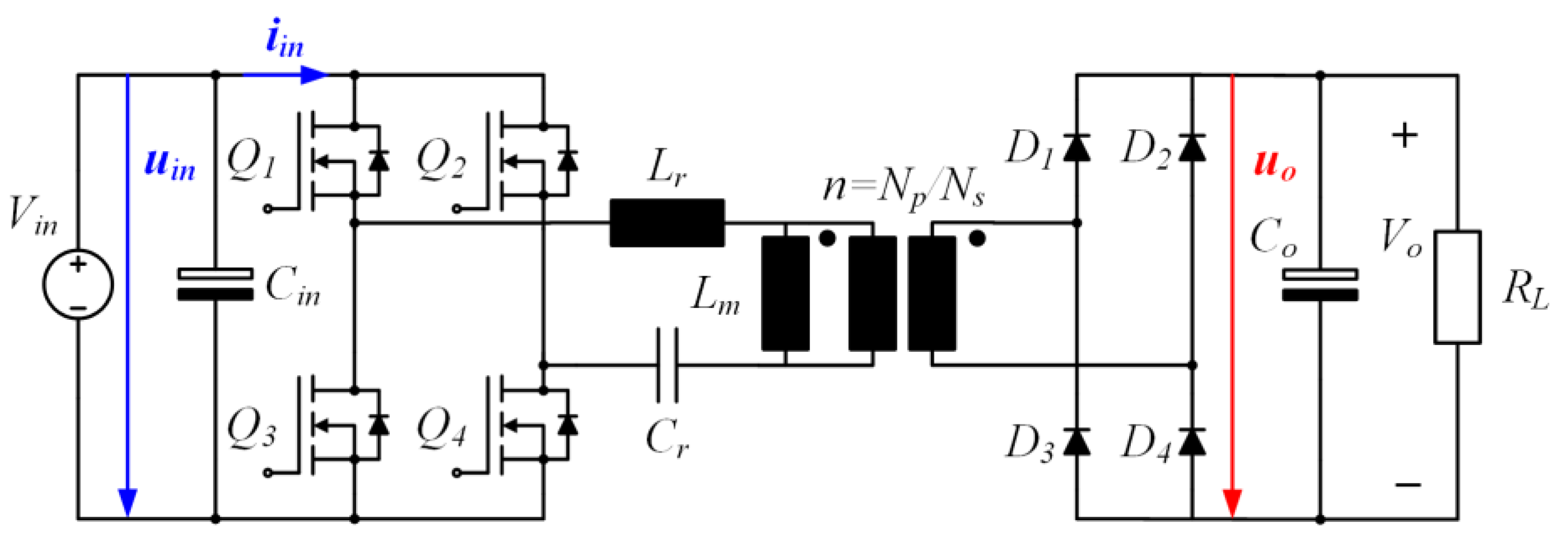
The schematic diagram of the power stage of the LLC resonant converter is presented in
Figure 1. The first stage of the
LLC comprises an H-Bridge inverter, responsible for converting the DC voltage from the TEG into high-frequency AC with a square-wave form aimed at exciting the resonant tank. Each leg of the H-Bridge is driven in a complementary manner with a 50% duty cycle, incorporating appropriate dead-time to mitigate the risk of short-circuits and ensuring sufficient time for achieving smooth commutation. The resonant tank consists of an inductance (
Lr) and a capacitance (
Cr) along with the magnetizing inductance (
Lm) of the transformer shunt. Following step-up to the desired level via the high-frequency transformer, the AC voltage is directed to the secondary diode-bridge rectifier. Finally, the resulting DC output voltage is either supplied to a DC bus (for grid-connected operation) or to a local load (for standalone operation).
Due to the high-quality factor (
Q) of the resonant tank, it is presumed that the current flowing through it resonates at the fundamental frequency, resulting in a sinusoidal waveform. Consequently, the analysis of the
LLC can be streamlined using the First Harmonic Approximation (FHA), as detailed in the literature [
28].
In accordance with the First Harmonic Approximation (FHA), the nonlinear, nonsinusoidal model depicted in
Figure 2a is rendered into the linear, sinusoidal model illustrated in
Figure 2b.
Utilizing Fourier analysis, the fundamental harmonic component of the H-Bridge output (
Vab,FHA) is determined as follows:
with a Root Mean Square (
RMS) value equal to
Next, the fundamental harmonic component of the output voltage, as reflected to the primary side (
Vso,FHA), is given by
with an
RMS value equal to
where
n represents the primary-to-secondary turns ratio (
Np/Ns), and
φα is the phase difference between the waveforms of
Vab,FHA(
t) and
Vso,FHA(
t). Given that the average value of the diode rectifier current is equivalent to the output load current, it follows that
with an
RMS value equal to
Hence, the equivalent resistance of the secondary circuit, as reflected to the primary side, can be expressed as
where
RL represents the load resistance. Finally, the transfer function of the
LLC, denoted as
GLLC, is derived from
Figure 2 as follows:
Equation (9) can be further simplified by considering the following parameters:
Hence,
GLLC can be expressed as
Regarding the voltage gain function, the control variable is the switching frequency (
fs), while
Q and
m are determined by the physical characteristics of the resonant circuit, remaining constant during the converter operation.
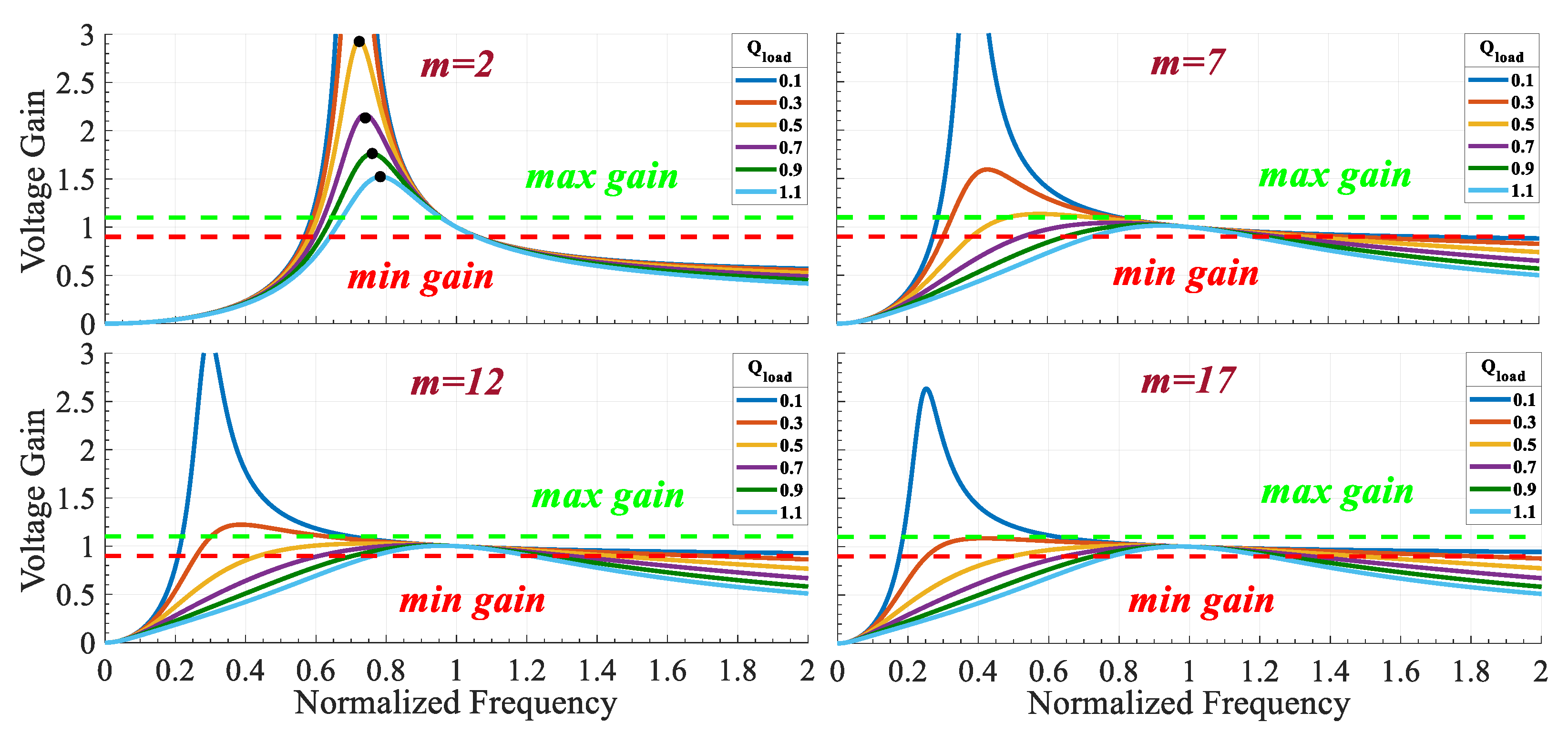
Figure 3 depicts the
LLC resonant tank voltage gain as a function of the normalized frequency (
Fx), for various values of
m, with
Q being a parameter.
Evidently, the peak resonant frequency (maximum tank voltage gain) is load-dependent; any alteration in m or Q values affects the curvature of these curves. Nevertheless, irrespective of the combination of m and Q, all curves intersect at the point (Fx, GLLC) = (1,1). Consequently, the LLC gain reaches unity when the switching frequency equals the resonant one, regardless of the load. In proximity to this juncture, the voltage gain remains independent of the load. Furthermore, for a constant value of m, an increase in Q constricts these curves, resulting in a narrower frequency operating range. Conversely, maintaining Q constant while reducing m shifts the peak switching frequency closer to fr, thereby narrowing the frequency modulation band and increasing voltage gains.
Last but not least, the
LLC must effectively achieve ZVS for the H-bridge switches, thereby reducing overall switching losses. The requisite ZVS conditions delineate the permissible operating area, which must lie to the right side of each peak resonant point. This area is denoted as the inductive region, owing to the inductive nature of the
LLC network impedance (where current lags). Conversely, the left side area corresponds to the capacitive region, which must be avoided to maintain ZVS functionality. In cases where both capacitive and inductive regions are permitted (in accordance with converter input/output specifications), the voltage gain exhibits nonmonotonic behavior, thus augmenting the complexity of converter control [
29].
3.2. LLC Converter Power Stage Design
Taking into consideration the theoretical analysis conducted previously to determine the GLLC transfer function (as a function of the design parameters of the LLC converter) for a TEG-based WHR system, this section presents a procedure for selecting the values of n, LLC tank gain range, m, Q, and the resonant components (Lr, Cr, Lm).
Step 1: Transformer turns ratio calculation.
The transformer turns ratio is chosen in a manner that facilitates the voltage step-up from the nominal input (15 V) to the nominal output (96 V) value. In this scenario, the tank gain is set to unity. Consequently, the output-to-input voltage ratio is
where
GFB represents the amplitude modulation index of the H-Bridge inverter (considered unity due to the square-wave modulation applied). Additionally, considering the voltage drop across the secondary side due to the bridge rectifier (approximately 1.4 V for two diodes in series), the transformer turns ratio becomes
n = 0.1562 (
Ns/Np = 6.4).
Step 2: Max./min. LLC tank gain values selection.
The minimum LLC tank gain value is necessary for the scenario where the input voltage reaches its maximum, and conversely, the maximum gain value is required for the case of minimum input voltage. Based on the specifications of the specific WHR application, the minimum and maximum input voltage values are defined as 10 V and 20 V, respectively. Additionally, to ensure reliability, an efficiency value of 95% for the nominal output power (150 W) is assumed, with a 10% margin considered for safety due to potential inaccuracies introduced by the FHA in the LLC model used for normalized frequency plots. Consequently, the LLC tank gain ranges from 0.749 to 1.736. The determination of the minimum and maximum input voltage values will be justified in the next paragraph, which analyzes the control strategy required for the active control of the converter.
Step 3: Q and m selection.
To circumvent the laborious trial-and-error process associated with arbitrary
Q-
m selection, a graphical approach is adopted to determine these parameters based on the gain-frequency plots shown in
Figure 3. Each curve exhibits a peak, referred to as the maximum attainable gain (
Gmag), which is denoted by black dots in the case of
m = 2.
Figure 4 illustrates
Gmag as a function of
Q for various
m values. A specific point must be chosen where the maximum attainable gain (
Gmag) exceeds
GLLC,max. This ensures that the converter meets the application requirements across all operating points. The selected
Q value corresponds to
Qmax, representing the maximum load of the application. Ultimately, the chosen values are
m = 4,
Q = 0.4, with
Gmag = 1.794 (greater than
GLLC,max = 1.736).
Step 4: Rac calculation.
For the nominal load scenario, the secondary circuit resistance reflected to the primary is calculated to be 1.18 Ω, as per Equation (7).
Step 5: Resonant components (Lr, Cr, Lm) selection.
For
m = 4 and
Qmax = 0.4, the nominal
Q value is 0.3636. Hence, it is derived as follows:
To validate the
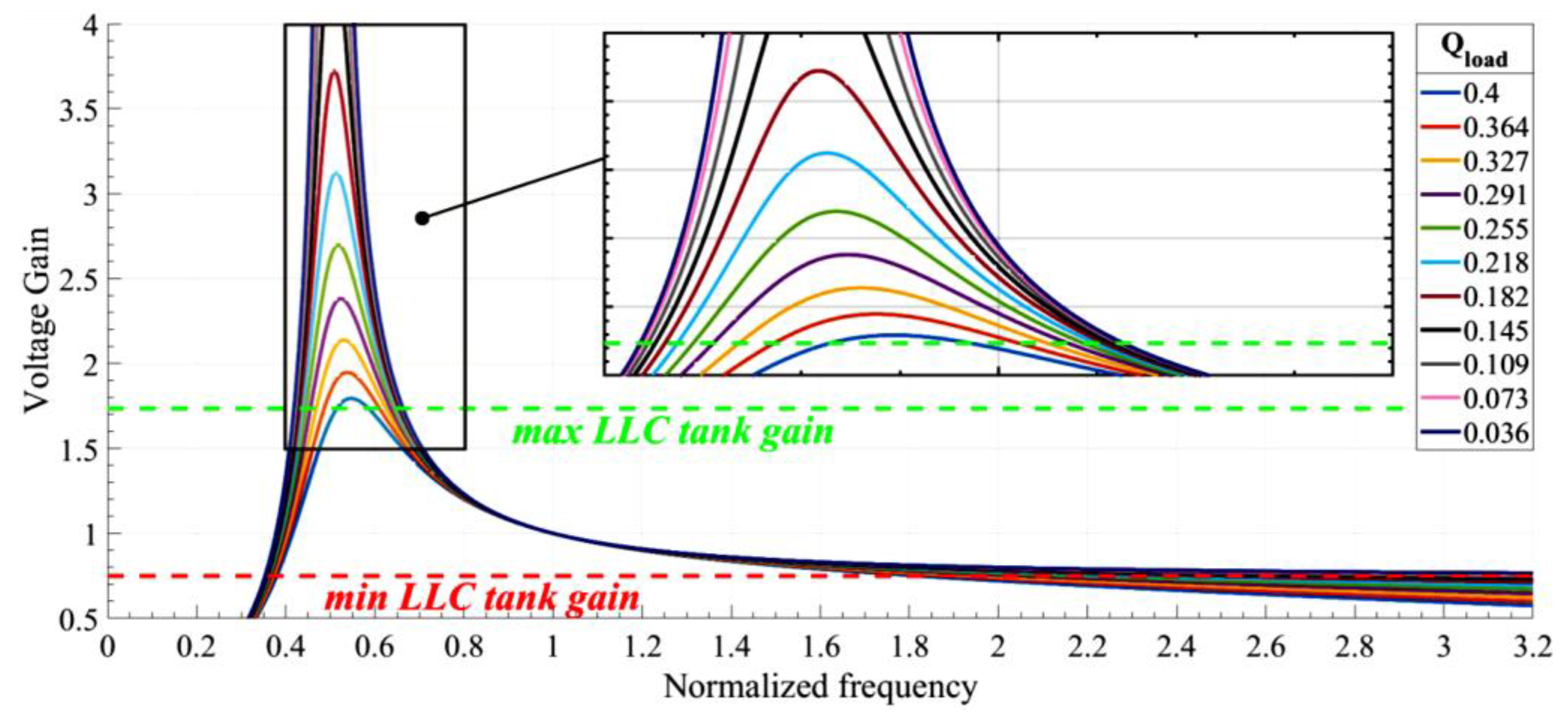
LLC design prior to simulations, the voltage gain as a function of normalized frequency is plotted for
m = 4 and variable
Q values, in accordance with the specific application load, as presented in
Figure 5. Evidently, all curves intersect with the horizontal lines representing the maximum and minimum required
LLC gain. Thus, the LLC tank is capable of adapting to the necessary gain for any load condition. Furthermore, the maximum gain of the blue curve (corresponding to the maximum quality factor) equals 1.794, which matches the
Gmag value corresponding to the selected
Q-m combination in Step 3. Consequently, the design is successful, as the required step-up ratio is achieved for all possible loads. By setting the minimum allowable frequency (
Fx) between 0.547 and 0.585 (where the blue curve intersects with the maximum
LLC tank gain), operation in the capacitive region is prevented, and the maximum required gain is attained. Finally, it is noted that, as the steady-state analysis of the
LLC converter has been widely presented in scientific literature, it is omitted here, whereas the exact mathematical expressions regarding ZVS ranges and voltage/current stresses on semiconductors for various
LLC configurations (e.g., full-bridge of half-bridge primary switch network, full-bridge of middle-point half/full-wave secondary rectifier etc.) can be found in [
29,
30,
31,
32,
33].
3.3. Control Diagram of the LLC Converter
Given that the LLC converter will supply either the DC bus of a hybrid shipboard microgrid or a local load with electric energy that is generated by a TEG-based SWHR system, it is inferred that the selected control method must accommodate various operational modes of the ship microgrid. Specifically, it should optimize the utilization of the TEG’s maximum output power across varying temperature and exhaust gas flow conditions emitted by the diesel internal combustion engine generator. Moreover, the control method must effectively regulate the LLC converter’s output voltage to ensure a constant voltage on the DC bus, even amidst sudden changes in electric load and TEG operational conditions. These requirements are relevant to different operating states of the ship, including maneuvering, sailing, or docking at ports.
Figure 6 depicts the curves of (a) output current and (b) output power of the WHR generator, as presented in the
Section 1 of this work, plotted as a function of its output voltage. These curves were obtained through simulations of the thermoelectric generator in a MATLAB/Simulink environment, considering a temperature difference Δ
T between the hot and cold sides of the TEG array ranging from 70 °C to 105 °C.
From the analysis of
Figure 6b, it can be derived that the maximum output power of the thermoelectric generator reaches 148.6 W, a value expected to be achieved during the nominal operation of the ship’s engine, and for a temperature difference Δ
T equal to 105.1 °C. A determining factor for the output power of the generator is the Reynolds number, which essentially expresses the effect of the inertia forces of gas flow relative to their viscous forces. This flow for diesel engines depends and corresponds directly in a 1:1 ratio to the load of the generator. Furthermore, from the study of the same figure, it becomes evident that the output power of the thermoelectric generator is not constant but it rather maximizes within a range of output voltage variation between 10 and 20 volts. Based on the above observations, it is inferred that to maximize the generated power of the thermoelectric generator, the input current of the
LLC converter must be drastically controlled. Techniques similar to those applied to find the maximum power point of PV generators can be applied to achieve this goal [
34,
35,
36]. Additionally, TEG power–voltage curves rarely present multiple local maxima and complex shapes, while dynamic changes are relatively slow compared to the corresponding photovoltaic curves. Considering the relevant literature, it was decided to employ the Perturb and Observe (P and O) algorithm with variable step-size in this specific application. The P and O algorithm can be digitally implemented using low-cost microcontrollers, without necessitating additional signals or sensors beyond those already employed by the
LLC power converter. Additionally, the adaptable convergence step facilitates the swift achievement of the global Maximum Power Point (MPP), thereby diminishing oscillations around the MPP and distinguishing it from local maxima. [
37,
38,
39].
The MPPT mode is applicable when the LLC converter feeds a DC bus of the shipboard microgrid, where maximum energy yield should be harvested by the WHR system. In parallel, this mode is also available when the converter supplies a local load, without the need for voltage regulation. On the other hand, the second control mode (CV) is applicable when the LLC supplies a local load and voltage regulation is imperative. The regulation of output voltage (CV mode) in response to fluctuations in input voltage and load demand is accomplished through the control of switching frequency, which adjusts the LLC voltage gain accordingly. Hence, the primary objective of converter control is to modulate the switching frequency to maintain the desired voltage gain across various load conditions. Specifically, the gain curves should encompass both the lines delineating the minimum and maximum required gain (GLLC maximum and minimum values) in order to ensure effective regulation of the output voltage.
Considering the aforementioned points,
Figure 5 illustrates the block diagram of the proposed control method, which comprises two alternative operating modes tailored to meet the specific requirements of the application. The controller is based on a typical Proportional-Integral (PI) compensator, in respect to
Figure 7, which has been finely tuned in order to present good dynamic performance (i.e., stability, no ringing, and fast recovery time) during load or input voltage step changes.
4. Simulation Results
To evaluate the high efficiency achievable with the proposed
LLC converter, LTspice simulations were conducted, comparing the proposed converter with the PSFB resonant topology. Notably, the PSFB was simulated in closed-loop control mode using phase-shift modulation. Commercial semiconductor switches and actual passive components were both incorporated into the study. The main components and parameters employed in the simulations are outlined in
Table 1. Additionally, a comprehensive analysis of power losses was undertaken for the selected
LLC, encompassing both theoretical evaluation and LTspice simulations, according to the procedure presented in [
40,
41].
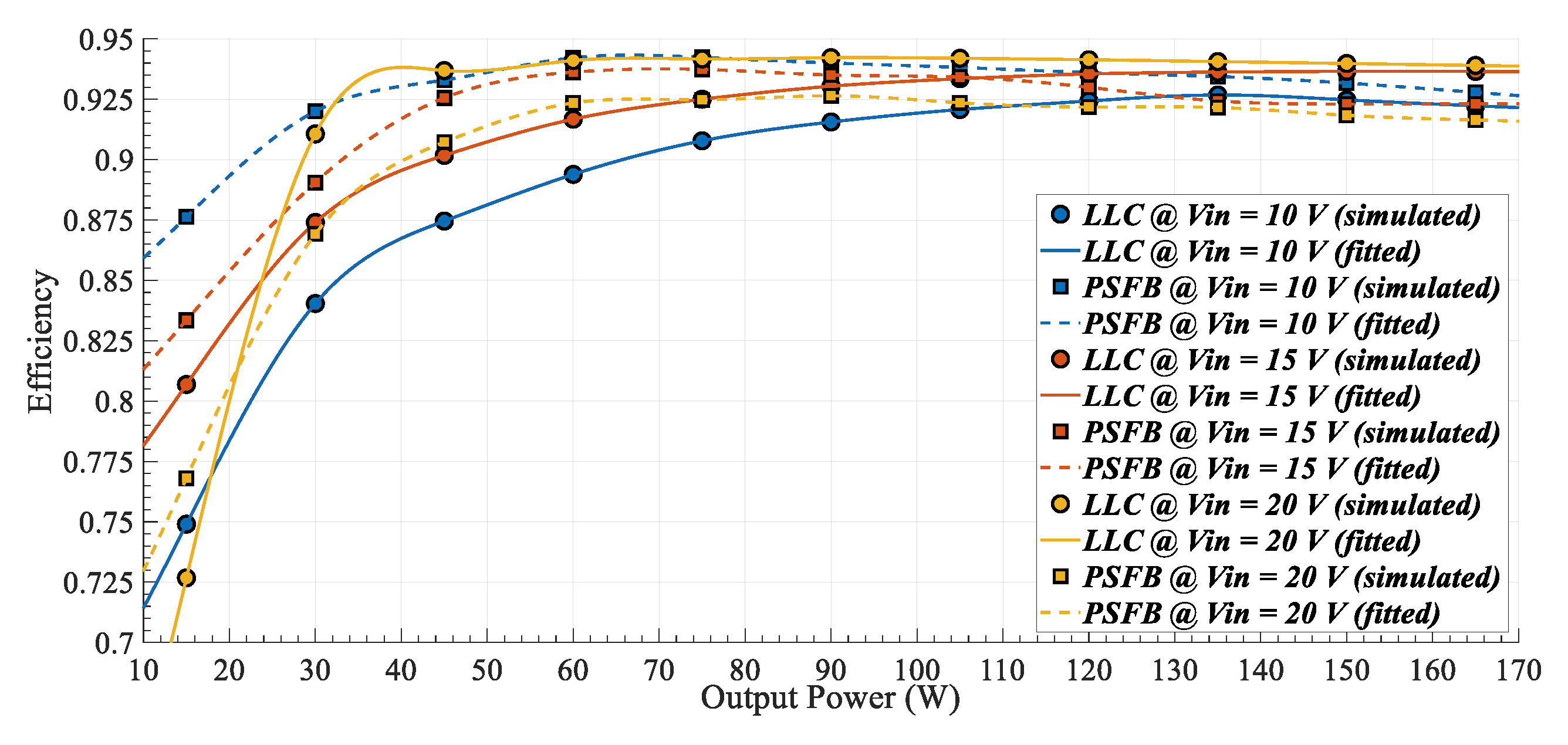
In
Figure 8, efficiency results (obtained via LTspice) are depicted for both the
LLC and the PSFB, considering constant input and output voltage values while varying the output power. The performance of these two converters appears to be closely matched. However, it is evident that the
LLC exhibits superior efficiency, reaching 93.4% at nominal output power. Conversely, the PSFB demonstrates slightly higher efficiency than the
LLC at extreme input voltage values; nevertheless, such operating conditions are anticipated to occur infrequently.
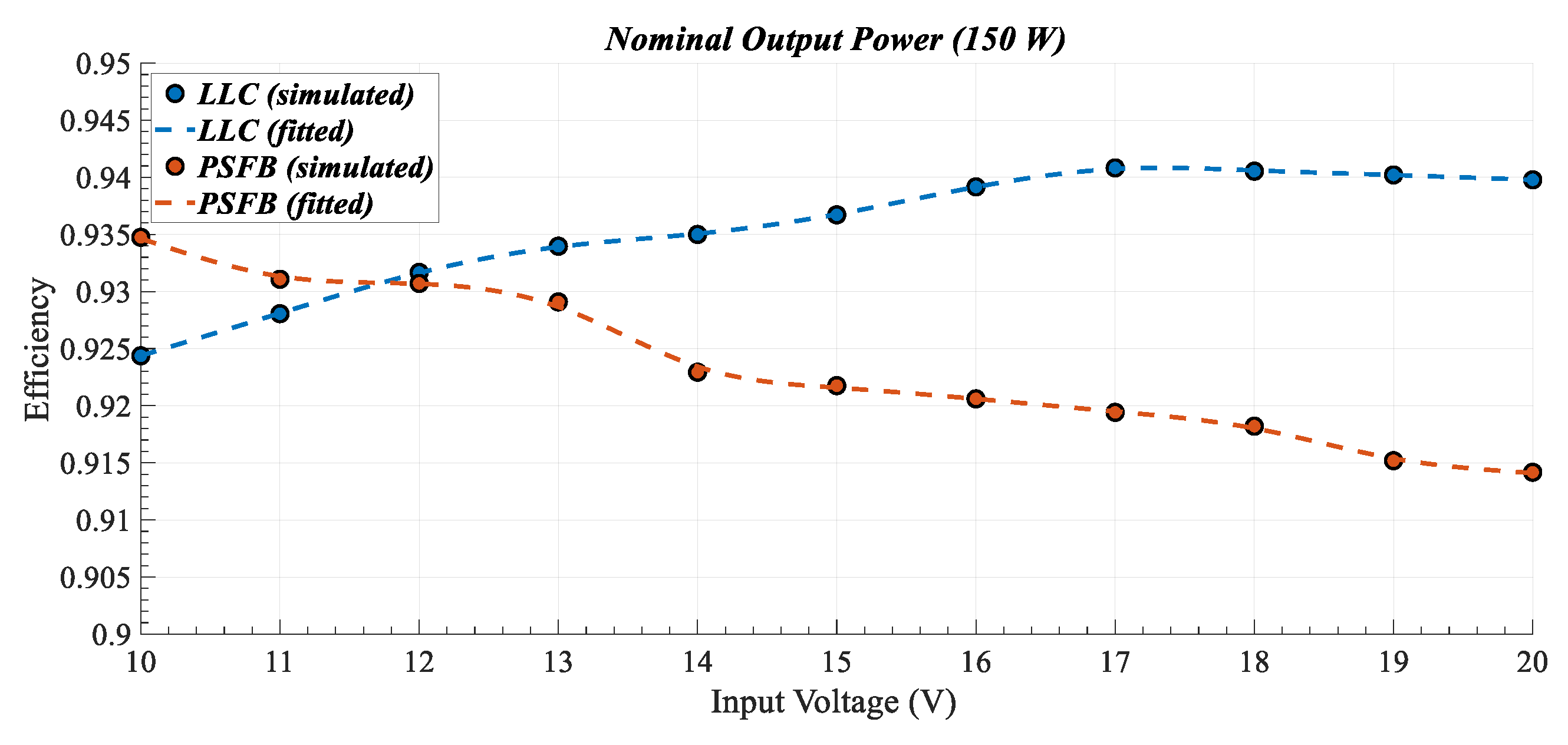
Furthermore, in
Figure 9, simulated efficiency is portrayed as a function of the input voltage while maintaining the output power constant at its nominal value. The
LLC demonstrates superior efficiency across a broader input voltage range, reaching a maximum observed efficiency of 94%. Conversely, the PSFB achieves its highest efficiency at V
in = 10 V, which corresponds to the minimum input voltage value. This observation aligns with the operating point where the H-bridge leg pulses experience zero overlapping. Considering these findings alongside the straightforward nature of
LLC control and modulation, its suitability for this specific WHR application is unequivocal.
Subsequently, a power loss analysis for the
LLC is conducted to identify their dominant components. The methodology for theoretical calculations is elaborated in detail in [
29]. The overall theoretical losses amount to 10.7 W, while the simulated losses derived from LTspice are 10.1 W.
Figure 10 illustrates the distribution of power losses for both cases. It is noteworthy that these results pertain to the nominal operating point (15 V to 96 V, 150 W), with both quantitative and qualitative similarity between them. Notably, the largest fraction of power losses (approximately 40%) corresponds to the diode-bridge rectifier. Furthermore, minor discrepancies arise due to inaccuracies introduced by highly nonlinear phenomena, such as the diode reverse recovery effect.
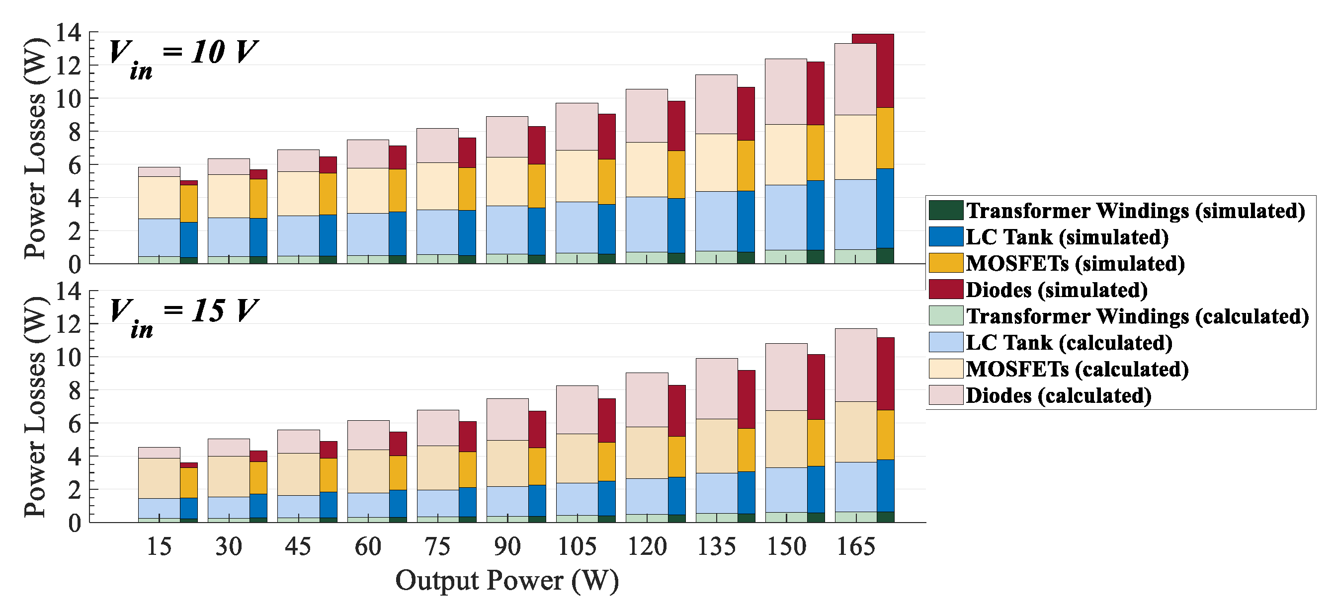
Finally, a quantitative representation of power losses (both theoretical and simulated) for various operating points (i.e., as a function of the output power) is presented in
Figure 11, considering input voltage values of 10 V and 15 V. It becomes evident that the power losses increase proportionally with the output power, with agreement observed between theoretical calculations and simulated results.
To validate the functionality and performance of the proposed control scheme, a MATLAB/Simulink model of the
LLC is developed. Initially, the MPPT control mode is evaluated. A worst-case scenario involving a step change in the temperature difference (Δ
T) from its maximum to its minimum value, and vice versa, is simulated, thereby altering the MPP accordingly. It is important to mention that the
LLC is interfaced with a 96 V DC bus. As illustrated by the simulation results presented in
Figure 12, the time taken to reach the MPP is less than 50 ms, which is deemed satisfactory for such applications. It is worth noting that in practical WHR systems, temperature variations are considerably slower.
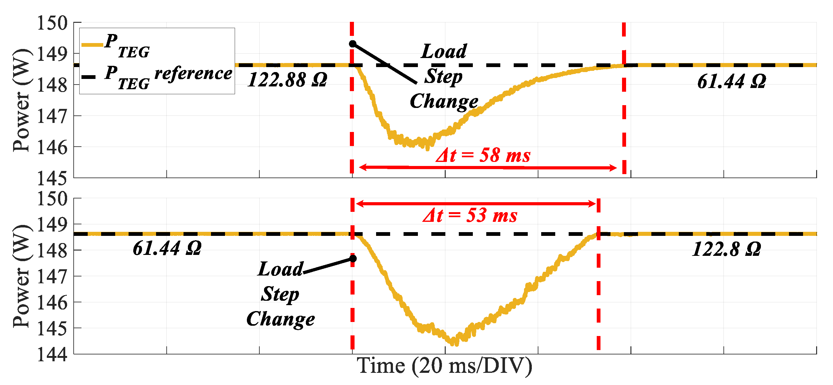
Furthermore, in
Figure 13, the MPPT operation is assessed while the
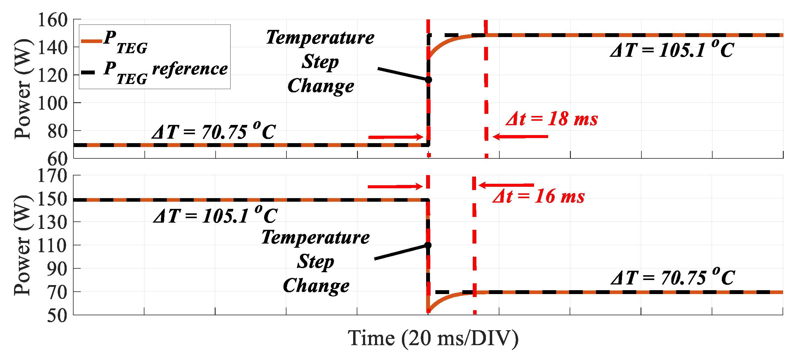
LLC supplies a resistive load, resulting in a non-constant output voltage scenario. A step change in the resistance value from 122.8 Ω to 61.5 Ω, and vice versa, is introduced. In both cases, the MPPT algorithm demonstrates high accuracy and speed, with a recovery time of less than 60 ms. Additionally, the TEG power exhibits a drift of less than 5 W during the transient time interval. The same test is conducted with a constant resistive load (i.e., 61.5 Ω), where a step change in the temperature difference (Δ
T) from its maximum to its minimum value, and vice versa, is applied. The results, as depicted in
Figure 14, underscore the outstanding dynamic performance of the MPPT algorithm, with the new MPP being detected in less than 18 ms. In summary, the functionality and effective performance of the MPPT mode are verified, whether the
LLC supplies a DC bus (DC grid-connected) or a resistive load (standalone operation).
The functionality of the Constant Voltage (CV) control mode is further validated. This mode is designed to maintain the output voltage at a predefined setpoint (i.e., 96 V for the subsequent tests), irrespective of variations in load and input voltage.
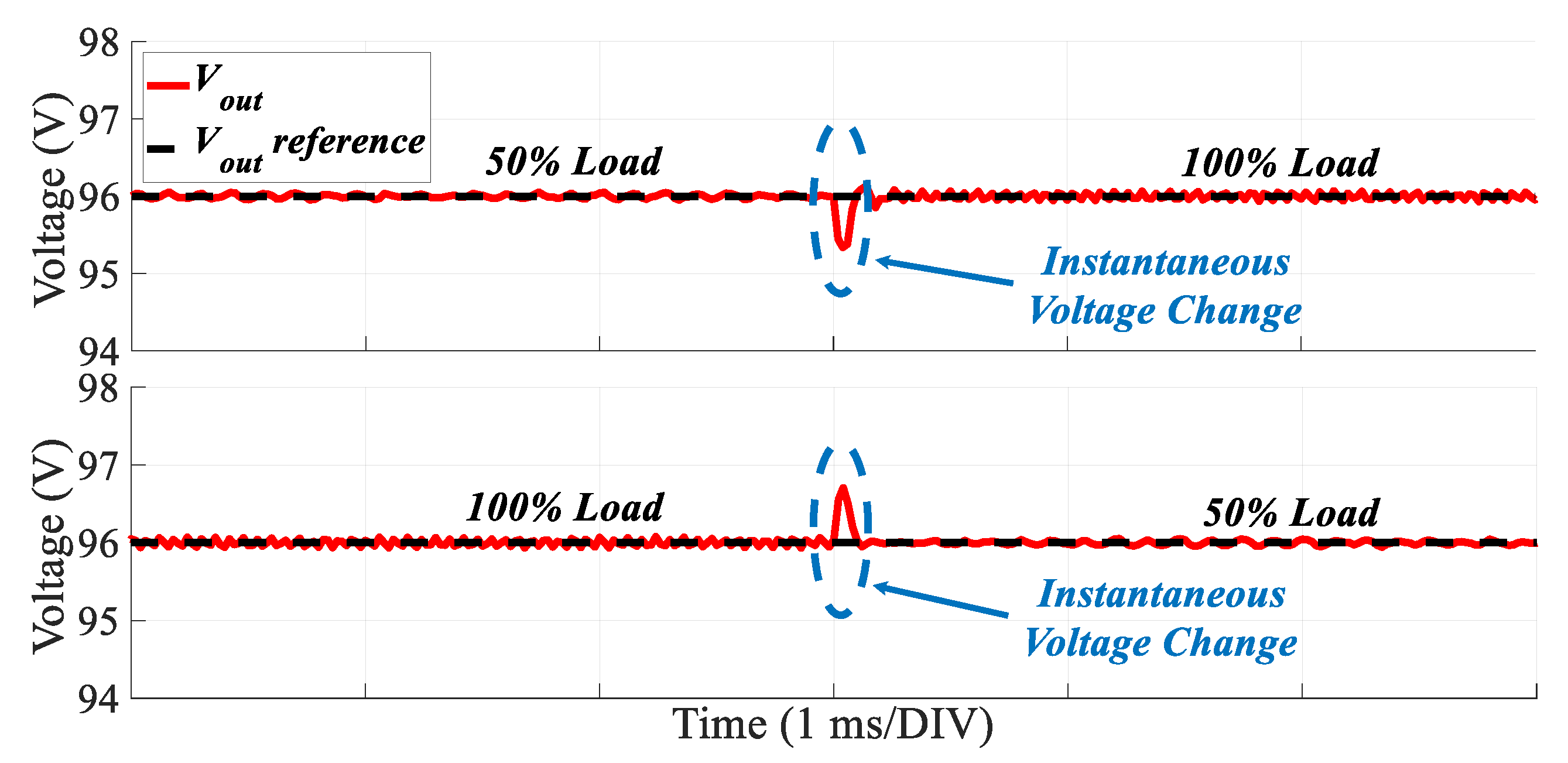
Figure 15 illustrates the output voltage when a load step change occurs, transitioning from its nominal (100%) to its 50% value, and vice versa. The controller exhibits a rapid dynamic response, with a voltage recovery time of less than 1 ms, while the voltage overshoot/undershoot remains below 1 V.
Additionally,
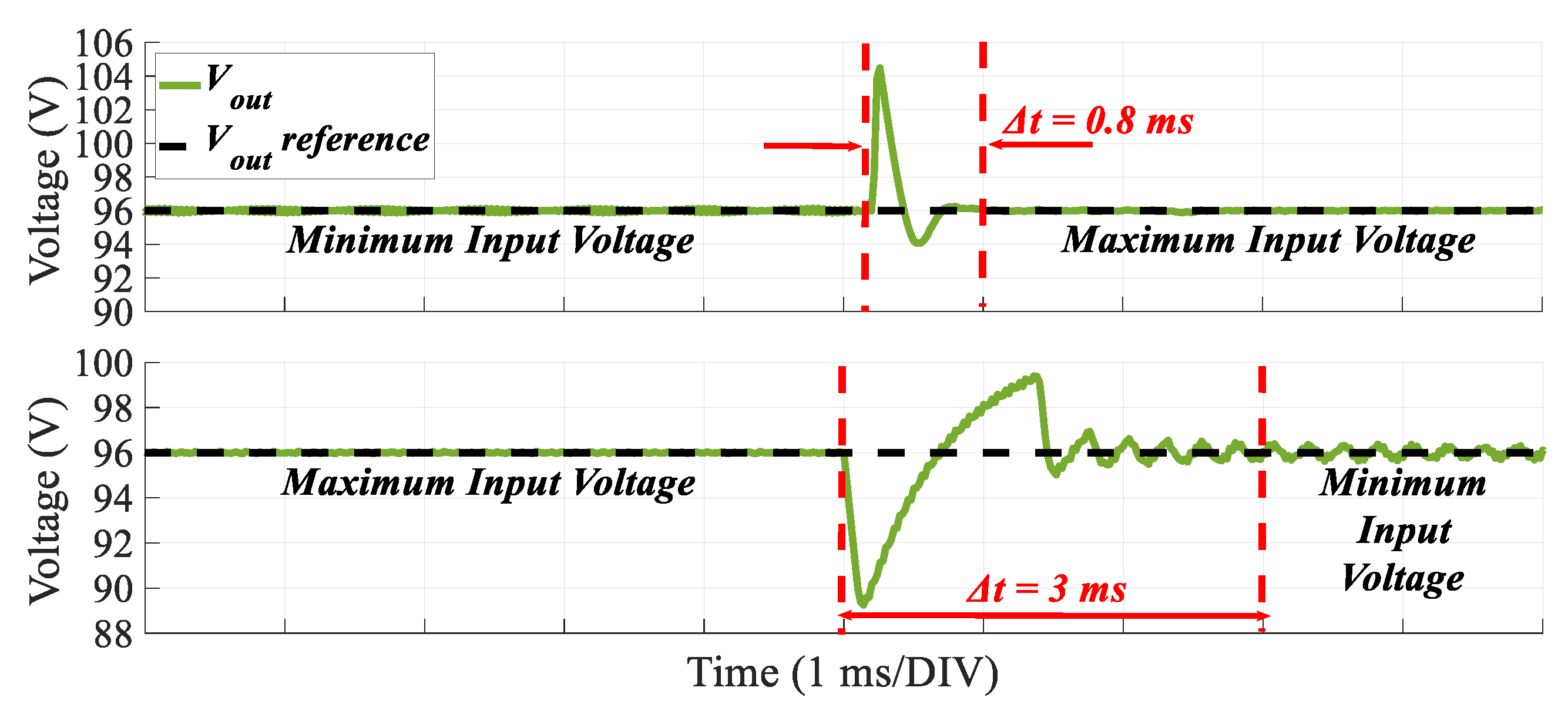
Figure 16 illustrates the output voltage response when a step change occurs in the input voltage, transitioning from its minimum to its maximum value, and vice versa, while the load remains constant at its nominal value. The controller demonstrates an adequate response, stabilizing the output voltage to the predefined setpoint in less than 3 ms, with overshoot/undershoot remaining below 8 V.
In summary, the simulation results presented above underscore the achievement of the objectives and requirements of the control strategy in both modes. The controllers (MPPT and CV modes) are proven to be fast and accurate, with minimal oscillations around the Maximum Power Point (MPP) and the output voltage setpoint.
Finally, in
Figure 17, the theoretical voltage gain curve is presented as a function of the normalized switching frequency for the nominal load case (from
Figure 5). Additionally, the operating points resulting from the simulations are depicted. It is evident that the operational points of simulations closely align with the theoretical curve, indicating the efficient study and design of the converter. Following the theoretical analysis and simulations, the proposed TEG system and
LLC step-up converter undergo an experimental validation on a laboratory testbench.
5. Experimental Validation
The primary objective of this portion of the study is to conduct tests on the converter under realistic conditions, aiming to underscore the effectiveness of the proposed SWHR system. Thus, a key aspect of this is the successful implementation of the two distinct control modes of the flexible proposed strategy, MPPT and CV, which were presented and studied through simulation in previous sections. Additionally, efforts are focused on assessing the extent to which the laboratory converter aligns with the theoretical analysis conducted earlier. To achieve this, voltage gain curves are experimentally generated as a function of the switching frequency, followed by a detailed analysis of their characteristics.
To evaluate the effectiveness of the
LLC converter operating under both operating modes (MPPT and CV), an experimental test bench has been established, as illustrated in
Figure 18. Specifically, the emulation of P–V characteristic curves of the TEG (as presented in the Introduction of this study) is enabled by the simulation interface of a fully programmable DC power supply, namely the SM 330-AR-22 model, coupled with a PV/ TEG simulation interface referred to as the INT MOD SIM, both obtained from Delta Elektronika [
37].
Additionally, to emulate either the 96 V DC-bus (for DC grid-connected operation) or a standalone load (for standalone operation) of the hybrid shipboard microgrid, a fully programmable DC electronic load, namely the PEL-3111H model from Gwinstek, was introduced. Moreover, a low-cost microcontroller development board, specifically the STM32 Nucleo-144, equipped with the STM32F429ZI microcontroller unit, was incorporated to control the switching devices of the LLC converter for both operating modes (MPPT and CV).
Figure 19 depicts representative results illustrating the performance of the developed P and O algorithm under various changes in MPP of the TEG unit. Specifically, it depicts the waveforms of the input voltage, current, and power for (a) a step-up change in power from 55 W to 147.5 W, (b) a step-down change in power from 147.5 W to 55 W, (c) a linear change from 55 W to 147.5 W, and (d) a linear change from 147.5 W to 55 W. From the analysis of these cases, it is inferred that the algorithm achieves successful MPP tracking in less than 2 s. Moreover, in all scenarios, the steady-state performance is found to be efficient, with only a minor divergence from the actual MPP.
Subsequently, the operational performance is validated in terms of
LLC voltage gain. To achieve this, a series of experiments were conducted in open-loop mode, encompassing various load current values.
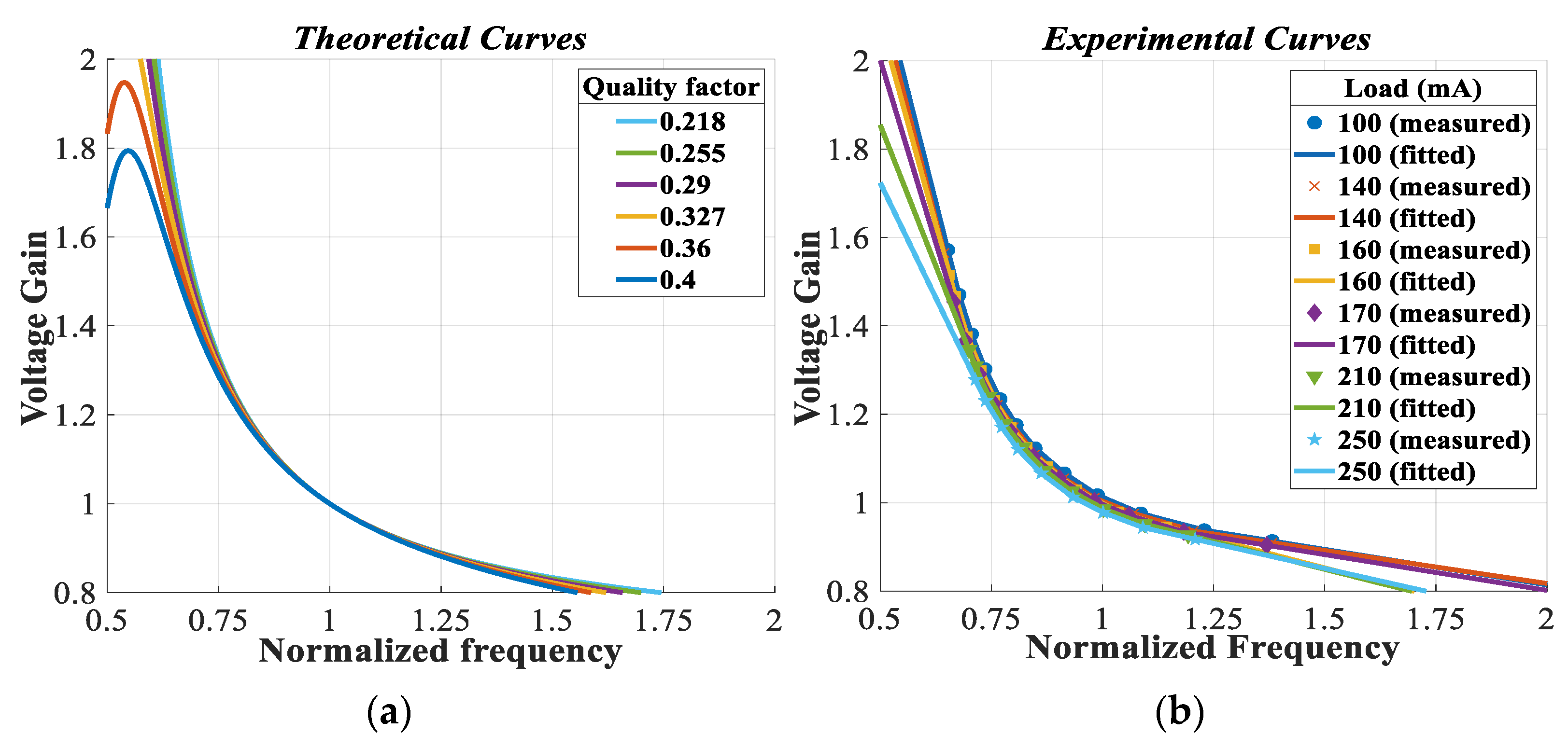
Figure 20 depicts the
LLC voltage gain in these tests as a function of normalized frequency, both theoretically,
Figure 20a, and experimentally,
Figure 20b. The analysis of these results reveals the satisfactory performance of the Frequency-Hopping Algorithm (FHA) for normalized frequencies close to unity. However, discrepancies between FHA predictions and real measurements are observed for frequencies substantially below 0.75 and above 1.25. Nonetheless, FHA remains a highly effective tool for designing and predicting the operational characteristics of the
LLC converter across a broad range of load and frequency conditions.
Finally, the closed-loop operation (constant output voltage mode with a reference voltage value of 96 V) is tested to verify the system’s ability to respond to dynamic changes in load or input voltage. In this context, several experiments were conducted where either the input voltage or the load current underwent step changes.
Figure 21 illustrates the system’s dynamic response for load current steps ranging from 850 mA down to 60 mA (a), and vice versa (b), for an input voltage of 20 V.
Additionally,
Figure 22 illustrates the system’s dynamic response to input voltage steps ranging from 20 V down to 17 V for load currents of 110 mA (a) and 450 mA (b) as well as to input voltage steps ranging from 17 V up to 20 V for load currents of 110 mA (c) and 450 mA (d). These results validate the excellent dynamic performance of the designed controller, attributed to the effective design of the LLC converter tailored for the specific application.
6. Conclusions
This article thoroughly examines the utilization of the LLC DC–DC power converter in interfacing a SWHR system in a ferry board microgrid. The key stages of the converter design are meticulously outlined and explained in depth. Additionally, a versatile control scheme is suggested, integrating both output voltage regulation and MPPT capabilities, selected to meet the application needs and load requirements. The effectiveness and operation of the entire system, comprising the power converter and the control strategy, are initially verified through LTspice and MATLAB/Simulink simulations. Following this, experimental tests are carried out on a laboratory-scale LLC hardware prototype. The obtained results confirm the feasibility of the proposed system over a wide operating range, highlighting its exceptional performance in terms of dynamic response.
Consequently, this study emphasizes the potential of thermoelectric WHR to significantly enhance the sustainability and energy efficiency of marine transportation, providing an inventive and adaptable solution for successful integration. Hence, the effective operation and good performance of the designed LLC converter, along with the proposed flexible control scheme, becomes the basis for the mass installation of SWHR systems in ships. Overall, SWHR systems are poised to play a significant role in enhancing the energy efficiency and sustainability of shipboard microgrids in the near future. Continued innovation, coupled with supportive regulatory frameworks and economic incentives, will drive their adoption and integration into mainstream maritime practices.

