1. Introduction
The memristor elements, based mainly on amorphous transition metal oxides, as TiO
2, HfO
2, Ta
2O
5, ZnO and other materials, have many potential applications, as in nonvolatile memory devices, artificial neural networks, and logical and reconfigurable electronic circuits [
1,
2,
3,
4]. The memristor was predicted in 1971 by Chua as the fourth fundamental, passive, and nonlinear one-port electronic element [
5]. It has a memory effect and can retain its state after switching off the electric sources [
5,
6]. The first physical prototype of a memristor, based on TiO
2, was proposed by Hewlett–Packard (HP) Research Team, supervised by Stanley Williams [
6]. In the scientific literature, information for generated polymeric, ferroelectric, and other types of memristors has been published [
7,
8,
9,
10]. Along with the oxide materials with resistance switching abilities already analyzed, the amorphous Ta
2O
5, doped by oxygen vacancies, has excellent switching properties, a sound dependability, great operating speed, small energy consumption, comparatively extensive memorizing time, and a good compatibility with the commonly used Complementary Metal Oxide Semiconductor (CMOS)-integrated circuits technology [
11,
12,
13,
14]. Due to this reason and to the increased interest of engineers and scientists to tantalum oxide memristors in the recent years, these elements and their promising applications are a central object of analysis in the paper. The tantalum oxide-based memory elements involve a high-conducting region and a channel, based on non-stochiometric Ta
2O
5 amorphous material [
15,
16,
17,
18]. The memristance (abbreviated from memory resistance) and the correspondent memristor status might be changed by applying outer voltage or current pulses [
19,
20,
21].
For an accurate description of the tantalum oxide memristors’ behavior in electronic digital and analog circuit and devices, a precise and simplified corresponding model is needed. Many attempts for adapting to the widely spread TiO
2 memristor models for approximate representation of the considered Ta
2O
5 memristors are available in the scientific literature [
11]. Conversely, the structure and principal of operation of TiO
2 and Ta
2O
5 memristor elements are distinct [
6,
11]. This is the major cause for the generation of various special tantalum oxide memristor models [
11,
13,
14]. The classical memristor model [
11] suggested by Hewlett–Packard Research Labs has a high accuracy and sound switching representation. It applies the standard Heaviside step expression in the differential state equation and a non-differentiable modulus expression in the respective
i–v relationship. Regrettably, these relationships are not flat and differentiable [
11,
13], and when this mathematical model is used for Simulation Program with Integrated Circuit Emphasis (SPICE) memristor model generation, many problems with the convergence exist [
22,
23]. This is a disadvantage of the traditional Ta
2O
5 memristor model. An improvement of the standard model is presented in [
13]. The modified tantalum oxide memristor model [
13] is related to a good precision and an enhanced behavior in SPICE environment. It uses continuous and differentiable relations in describing equations as an alternative of the applied non-smooth and non-differentiable expressions in [
11]. While the enhanced tantalum oxide-based memristor model [
13] is appropriate for SPICE incorporation, it is a computationally complex and time utilizing one, owing to the applied modulus-like complex expression. It demands many elementary calculations, corresponding to the high number of exponents in the state equation [
13,
14]. No window has been included in this model, and sometimes, the state variable
x might go outside the interval between 0 and 1 when the memristor operates in a hard-switching mode. This is one more disadvantage of the discussed memristor models. A distinct memristor model, presented in [
16], is appropriate for Ta
2O
5 memristor representation. It has good accurateness and correctly represents the switching processes in the memristor element. Disappointingly, it is founded on the classical non-differentiable step function, which is associated with convergence issues [
20]. The memristor model represented in [
15] is relatively simple and accurate, with a high operating rate.
The motivation for the present paper is the partial absence of simple and accurate Ta
2O
5 memristor models. The purpose of this research is to propose and consider an accurate, adjustable, fast operating, and simple model [
12] for Ta
2O
5 memristors appropriate for generation of corresponding Linear Technology SPICE (LTSPICE) [
23] library model. LTSPICE is a simple, user-friendly, and free software for analysis and design of electronic circuits and devices by preliminary computer simulations [
23]. This software is offered by Analog Devices Corporation and could be freely downloaded and installed, using the next link:
https://www.analog.com/en/design-center/design-tools-and-calculators/ltspice-simulator.html (last accessed on 5 November 2021). LTSPICE software is preferrable for electronic device simulations by many design engineers and scientists. For adjustment of the offered memristor model, experimental current-voltage characteristics of tantalum oxide memristors, results derived from the use of several of the best existing models [
11,
13,
14], and different methods for optimal parameters’ estimation [
22,
24] are applied. The parameters’ estimation procedure is realized in the MATLAB environment [
22]. The least mean square error (MSE) between the experimental and simulated voltage–current relationships is used as an optimization criterion [
22,
24,
25]. A corresponding LTSPICE library memristor model is successfully created. It is included in a unified and open LTSPICE memristor library, freely available for download and use at:
https://github.com/mladenovvaleri/Advanced-Memristor-Modeling-in-LTSpise (last accessed on 9 November 2021) [
26]. The proposed memristor model is analyzed and tested in passive and hybrid memristor memory crossbars for reading, writing, and erasing processes [
27,
28,
29,
30]. The derived current–voltage and state-flux relationships confirm the proper operation of the considered tantalum oxide-based memristor model for soft-switching and hard-switching modes.
The rest of this paper is organized as follows. A description of the basic tantalum oxide memristor models is shown in the next section. The adjustment of the offered memristor model using experimental
i–v characteristics, a procedure for extraction of the optimal model’s parameters, and a procedure for coefficients’ assessment in MATLAB—Simulink environment are discussed in
Section 3. The related LTSPICE memristor model and its analysis are described in
Section 4. The operation of the commented LTSPICE memristor library model in passive and hybrid memristor crossbars is shown in
Section 5. The results are discussed in
Section 6. The conclusion is given in
Section 7.
2. The Basic Existing Ta2O5 Memristor Models and the Proposed Modification
For better understanding and completeness of the models’ description, the basic existing standard and modified Ta
2O
5 memristor models are briefly discussed in this section. The tantalum oxide memristor element has two terminals—top electrode (TE), also known as anode, and bottom electrode (BE), namely the cathode [
11,
18]. These electrodes are made of platinum or tantalum-layered materials [
11]. Several modified physical realizations of tantalum oxide-based memristors with layered structure are available [
19]. This two-terminal passive electronic element has a cross-section with a square shape. The injection of oxygen vacancies is conducted by electroforming-like process at comparatively low-level voltage pulses [
11]. In the Ta
2O
5 memristor nanostructure, several parallel-oriented conducting channels are available [
18,
19]. The peripheral region is based on pure and stochiometric Ta
2O
5 amorphous material [
11]. The central conducting channel is founded on a consistent solution of О atoms in a crystalline Та material. A transitional region, made of a non-stochiometric Ta
2O
5 and partially doped with O
2 vacancies, is created among the central and the peripheral channels of the tantalum oxide memristor element [
11,
19]. The memristor status could be changed by the use of outer voltage pulses. According to several physical factors, as the effective ionic dopant mobility, the memristor length and the resistance in the operating state, the memristor could function at different frequencies and amplitudes of the applied signals, representing the change of the memristance and the correspondent state variable. The following tantalum oxide memristor models are able to properly represent the memristor behavior for low, middle and higher frequencies for hard- and soft-switching modes. The memristor state variable
x [
11,
13] is stated as a ratio of the areas of the intersections of the low-resistance channel, denoted by
a1, and the area of the whole nanostructure, expressed by
a2 [
11]:
According to physical considerations (
a1 ≤
a2), the memristor state variable
x is limited in the range (0, 1). The described physical limitation of the memory element’s state variable for the memristor models could be mathematically realized, using an appropriate window function [
7,
8,
28]. If a voltage signal with comparatively low level and high frequency is applied to the memristor, then its state variable
x does not reach its limiting values. This operation is also known as a soft-switching mode. In such a case, the correspondent current–voltage relationship is a multi–valued pinched hysteresis loop, and the respective state-flux relation is a single-valued curve. For higher-level and lower-frequency signals, the state variable
x could reach its boundary values—zero and unity. In this case, the memristor operates in the so-called hard-switching mode. This functioning is related to a rectifying effect [
7,
8,
31]. The terminal-state problems are related to the impossibility of the state variable
x to be changed when it reaches its limiting values. Some window functions, as these proposed by Joglekar and Williams [
6,
31], are related to terminal state problems, while others as Biolek’s [
7] are able to correctly resolve these problems. In the present case, terminal state issues are not established, owing to the use of a modified Biolek-based window function [
12,
26].
2.1. The Standard Model of Ta2O5 Memristor, Proposed by HP
The highest value of the
memductance (abbreviated from
memristor conductance) of the Ta
2O
5 memristor is denoted by
Gmax [
11,
13]. The conductivity of the doped layer of the memristor could be represented by the Frenkel–Poole equation [
11,
13]. According to the traditional HP model of tantalum oxide memristors [
11], the state-dependent current–voltage relationship could be described as:
where
i is the memristor current,
v is the applied voltage across the memristor,
Geq is the equivalent memductance, and
a and
b are tuning parameters. The state differential equation of the standard tantalum oxide memristor has the following expression [
11]:
where
A, B, σOFF, σON, σP, xON, β and
xOFF are coefficients for adjustment of the model [
11,
13,
31]. The memristor model is based on a nonlinear dopant drift representation [
11]. The applied in the model Heaviside step function
stp(·) is [
7,
8,
25]:
The classical HP tantalum oxide memristor model [
11] is completely characterized by (1) and (2). This model holds good accuracy, related to an RMS error of about 2.86% [
11,
13]. It might correctly describe the performance of memristors, based on amorphous tantalum oxide in electronic schemes and devices [
11,
13]. The main drawbacks of the model, related to SPICE realization, are the application of an interrupted and non-differentiable step function and a non-smooth and non-differentiable modulus function [
11,
13]. The analysis of the memristor model is realized by computer simulations in MATLAB environment [
22]. The simulations are prepared on a desktop computer system with Intel
i5, 2.4 GHz 4-core microprocessor, Windows 10 system, and 8 GB Random Access Memory (RAM) [
12]. The time for simulation of this memristor model is
t1 = 49.5 ms.
2.2. Enhancements of the Classical HP Memristor Model
The major improvement included in [
13], which enhances the SPICE realization of the memristor model, is the replacement of the classical modulus expression and the standard step function by differentiable and flat replacements [
25]. A simple step-like differentiable relation, applied in [
13,
14], is:
where
k is a tuning coefficient [
13,
25]. It determines the steepness of the step-like function
stpp(.) in the region of switching [
25]. For SPICE realization, it usually has a value between −50 and −1000 [
13,
14]. A differentiable and flat analog of the classical modulus function, used in (2) is [
13,
14]:
where
ρ is a parameter for fitting the modulus function [
13]. Usually, for SPICE realization, its value is between 100 and 1000 [
13,
14]. The main improvement in this memristor model is the realized prevention of convergence difficulties in SPICE environment [
13]. This model is with good accuracy, and the related error is about 2.88%. A disadvantage of the described memristor model is its comparatively high computational complicacy. The necessary time for simulation of the considered tantalum oxide memristor model is
t2 = 16.8 ms.
2.3. The Proposed and Considered Improved Tantalum Oxide Memristor Model
The proposed modified memristor model [
12] contains several main replacements. First, the classical step expression
stp(
v) in (3) is substituted by a smooth and differentiable analogue
s(
v) [
12,
25]:
where
m is a coefficient with a typical value between 0.01 and 0.0001 [
12,
25]. This coefficient determines the steepness of the step-like function in the region of switching [
25]. The function expressed by (7) is an alternative of (5). An advantage of such a step-like continuous function is the partial avoidance of convergence problems in SPICE environment. Conversely, the correspondent region of switching is not as sharp and rigorously defined, as in the case of the classical Heaviside function [
25]. This could lead to decreasing the accuracy of the respective memristor model, especially if it operates at low-voltage signals and soft-switching mode. A compromise between the model’s accuracy and the prevention of convergence issues must be introduced, and the coefficient m could be used as a parameter for adjustment of the memristor model. Due to the use of simple mathematical expressions and avoiding the exponential function applied in (5), the memristor model based on (7) has a slightly higher operating speed [
12]. The operating rate is related to the number of the elementary mathematical operations in the memristor model, when it is functioning in a software environment, as MATLAB [
22] or SPICE [
23]. Second, the fragment
in (2) is approximated with a low-order polynomial:
which holds almost equal values in the interval (−1 V, 0.5 V). The RMS error among the original term and its approximation in (8) is about 2.8% [
12]. The coefficients
h1,
h2 and
h3 in the right-hand position of (8) are parameters for adjustment of the polynomial [
12,
22]. The applied approximation in (8) ensures lower complexity of the considered tantalum oxide memristor model, compared to the model described in [
11]. Third, a modified and comparatively simple window representation
fBmod(
x,i), founded on both the classical window expression proposed by Biolek [
7] and the described step-like function
s(
i), is used in the considered memristor model [
12]:
The applied window function is able not only to restrict the state variable
x in the interval (0, 1) but also to correctly represent the boundary effects and to solve the terminal state problems [
7,
12]. The terminal state problems are related to several memristor models, as Strukov–Williams, Joglekar and others [
8]. Sometimes, when the state variable reaches the physical limits of zero and unity, it cannot be changed, although the applied voltage and the correspondent flux linkage are with sufficient values and polarities. Other models, such as Biolek and Boundary Condition Memristor (BCM) models, resolve successfully this issue [
8]. The term
s(
−i) is a smooth and differentiable step-like function, used for prevention of convergence issues in SPICE environment [
13,
14]. The memristor state differential Equation (3) [
12] of the described model might be expressed in the next form:
where the terms
M(
v),
E(
x,i,v),
C(
v),
J(
x,i,v), are expressed according to (3) as follows:
Here,
A and
σOFF are fitting parameters [
11,
13]. Unfortunately, the steepness of this term as a function of
v is high in some voltage ranges and cannot be correctly approximated, unlike the term
C(
v). The next term in (10)
E(
x,i,v) is expressed by (12):
where
β and
xOFF are parameters for adjustment of the memristor model [
13]. The term (12) is also not appropriate for approximation and simplification [
13]. The term
C(
v) is successfully approximated by a low-order polynomial [
12]:
where
B,
σON, k1,
k2 are fitting coefficients [
12]. The coefficients
k1 and
k2 are derived using the least squares approximation method, realized in MATLAB environment [
22]. The RMS error between the original and the approximated values of
C(
v) in the interval (−1.45 V, 1.45 V) is about 2.4% [
12]. The next term
J(
x,i,v) is [
11,
12,
13]:
Here,
σP, xON are fitting parameters [
11,
13]. The final term in the state equation, presented by (14) could not be appropriately simplified. The original and the approximated expressions of the memristor current
i as a function of the applied voltage
v and the equivalent memductance of the tantalum oxide memristor
Geq(
x,v) are [
12]:
The proposed simplified and improved tantalum oxide memristor model is completely described by (10) and (15) [
12]. The model has good precision, and the obtained error is about 2.93%. It is able to properly operate in high-frequency mode, representing the respective alteration of the state variable
x for both soft-switching and hard-switching operation [
12].
3. The Fine Tuning and Parameters Estimation of the Suggested Memristor Model
The enhanced tantalum oxide-based memristor model [
12], considered in this paper and fully described by (10) and (15), includes several parameters for fine adjustment. It is tuned in accordance with voltage–current characteristics, obtained by experimental data [
11,
19], the original HP model [
11] and several of the best and accurate models [
11,
13,
14,
19], and it employs a procedure for changing the model’s factors until reaching the total minimum of the RMS error [
12,
22]. Several researchers [
31,
32] have applied simulation annealing and gradient descent techniques for deriving the best parameters of the optimized memristor models. Additional comparison to several of the best tantalum oxide memristor models [
11,
13,
14] is conducted, applying current–voltage and the correspondent state-flux relationships. Considering the terms (8), (13), and (10), (15), it could be easily concluded that the evolution of the memristor state variable x depends mainly on its initial value x
0 and the history of the applied voltage signal. The retention of the memristor state and the related information stored in the element are dependent on the state variable and the corresponding memductance. The processes of internal diffusion of dopant ions could affect the memristor state, but over a long interval, practically about ten years [
11,
19]. Owing to this, additional terms for considering the reliability and retention [
33] related to the tantalum oxide memristor are not included; thus, the model must be simple and applicable for analysis of memristor-based schemes and devices. A technique for extraction of the memristor model’s parameters in the MATLAB environment [
22] is also applied. The considered method for optimization of the tantalum oxide memristor model’s tuning is based on altering the coefficients and searching for the global minimum of the RMS error among the experimental and the obtained-by-simulations
i–v relationships. At each iteration, one of the parameters of the memristor model is changing by a little constant increment [
12]. The corresponding RMS error between the experimental and the simulated current–voltage characteristics is calculated. The other coefficients for tuning the memristor model are also altering. After finishing the course of this tuning process, a graphical observation of the simulated
i–v relation and its closeness to the experimental current–voltage characteristic is also established [
12], paying attention to the shape of the obtained pinch hysteresis loop and especially its regions of switching the memristance [
12]. The corresponding time diagrams of the experimental and the simulated memristor currents are compared as well, applying the squared differences between them in the sampling points.
The decisive factor for finishing the tuning procedure is the minimization of the RMS error [
12,
22,
24]. Supplementary tests and simulations are made in the proximity of the derived optimal levels of the tantalum oxide memristor model’s coefficients, using decreased increments for their changing [
12]. The precise and optimal levels of the memristor element model’s coefficients are also established, applying the least squares method in Simulink environment, using the Optimization Toolbox [
22]. The technique for memristor model’s parameters estimation could be approximately summarized in several basic steps:
Initialization of the values of the model’s parameters, using the coefficients in the original sources [
11,
13,
19] and the coefficients in the polynomials (8), (13) after their approximation in MATLAB environment [
22];
Defining the satisfactory root mean square error for stopping the procedure, the respective tolerances and the maximal iteration steps;
Starting simulation and calculating the values of the memristor current, according to the applied model;
Estimation of the root mean square error (the cost function) between the experimental and the calculated memristor currents;
Changing the model’s parameters, according to the gradient descent of the cost function, then proceed to step 4;
If the satisfactory root mean square error is reached, or the maximal iteration steps are finished, stopping the simulation and estimation of the obtained model’s parameters; if not, proceed to step 5.
The applied voltage signals in the Simulink model of the memristor are hitherto sampled, and the time step is 10 µs. The voltage drop across the element
v1 is applied as an input signal, applied to the Simulink model of the considered memristor [
12,
22]. The empirically recorded memristor’s current is denoted by
imes. The simulated output of the Simulink memristor model is equivalent to the simulated current of the tantalum oxide memory element
icalc. The cost function
Scost is represented by a sum of the squares of the differences of the calculated and experimental memristor current’s values [
12,
22]:
where N = 200,000 is the total amount of samples of the considered signals, and
k is the actual sample. The benchmark for finishing the parameters’ estimation procedure minimizes the cost function
Scost [
22,
32]. The best possible values of the extracted memristor model’s coefficients are presented in
Table 1 for the generation of the LTSPICE tantalum oxide memristor library model, as discussed in the next section. The derived optimal values of the tantalum oxide memristor model’s coefficients are similar to those obtained in other scientific works on tantalum oxide memristors [
11,
13,
14]. The obtained values of the coefficients
k1,
k2,
h1,
h2 and
h3 after approximations in MATLAB environment [
22] ensure that the RMS error between the respective terms is lower than 0.8%.
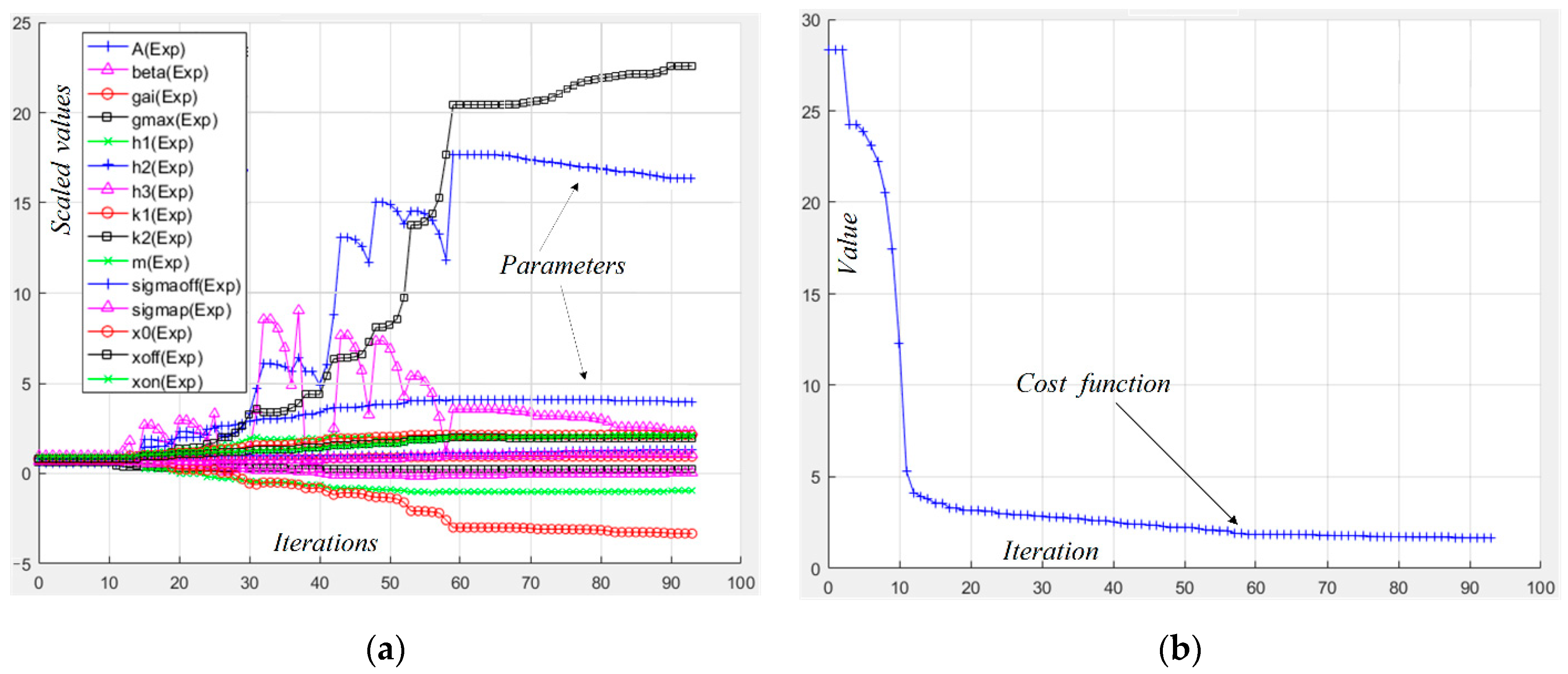
The scaled values of the trajectories of the model’s parameters during the optimization are shown in
Figure 1a to present their change with time. The initial values of the model’s parameters are chosen to be close to those obtained in [
11,
13], and the memristor state variable
x is in the space (0, 1).
For a brief comparison of the presented model to some of the existing and frequently used tantalum oxide memristor models [
11,
13,
14,
15], several basic criteria, as simulation time, operation speed, accuracy and convergence are presented in
Table 2.
The minimization of the cost function
Scost is given in
Figure 1b to show the correctness of the optimization process [
12]. The time diagrams of the memristor current (experimental and simulated) and voltage after the optimization are presented in
Figure 2a for confirmation of the sufficient closeness between them. The experimental current–voltage characteristic [
11] and the simulated
i–v relationship obtained in the MATLAB environment [
22] are presented in
Figure 2b to present the proximity between the characteristics. The obtained RMS error is about 3.24%. The time for simulation of the memristor model
t3 is about 16.3 ms [
12].
Owing to the modified and simple equations, the suggested model of Ta
2O
5 memristor operates more rapidly than the formerly expressed memristor models [
11,
13,
14]. The derived state-flux relationships for soft-switching and hard-switching operations are presented in
Figure 2c,d, respectively, for confirmation of the proper functioning of the suggested modified memristor model [
12]. The state-flux characteristic of the tantalum oxide memristor for soft-switching mode is a pinched hysteresis loop, while for the hard-switching operation, it is a hysteresis curve, correspondent to the memristor boundary effects [
31].
4. The Corresponding LTSPICE Memristor Library Model
Based on the proposed improved mathematical memristor model, described by (10) and (15), an LTSPICE [
23] library model of the described tantalum oxide-based memristor element was created [
12,
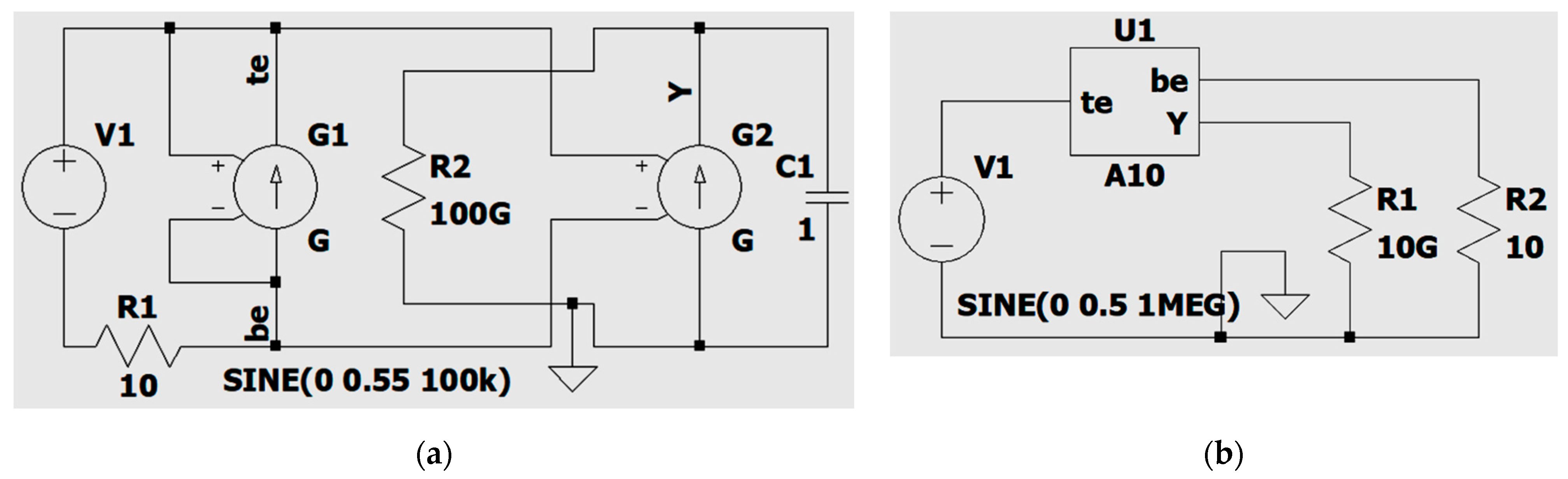
26]. The basic functional units in the LTSPICE environment are employed for realization of the relevant math calculus, in accordance with the presented memristor model. The substituting schematic of the generated LTSPICE model is shown in
Figure 3a for further discussion. The memristor variable
x is realized as the voltage
V(
Y) of the capacitive element
C1 [
12,
26]. Its current corresponds to the time derivative of
x. The two-port voltage controlled current source
G1 represents the memductance
G of the tantalum oxide memory element. The internal own resistance of the applied voltage source
V1 is represented by the resistance
R2. The resistor
R1 prevents the occurrence of convergence issues [
12,
13]. The generated LTSPICE memristor library model in a simple electric circuit is presented in
Figure 3b. The main terminals are the top electrode (TE, anode) and the bottom electrode (BE, cathode). The additional electrode
Y is applied for measuring the memristor state variable
x [
12,
13].
The correspondent LTSPICE code of the memristor model is [
12,
26]:
.subckt A10 a c Y
*terminals—top electrode (a), bottom electrode (c) and additional
*electrode Y for measuring the memristor state variable
.params yon = 0.04 A = 1.37 × 10⁻⁷ sigmap = 7.05 × 10⁻⁵ sigmaoff = 0.042
.params Gm = 0.027 yoff = 0.27 m = 6 × 10⁻¹⁰ beta = 822.6 k1 = 0.0062
.params k2 = 0.0001 h1 = 1.98 × 10⁻⁴ h2 = 0.000135 h3 = 3.31 × 10⁻⁴
*memristor model parameters for tuning
G1 a c value = {(V(Y) × Gm +(1 − V(Y)) × (h1 × (pow(V(a,c),4)) + h2 × (pow(V(a,c),2)) + h3)) × V(a,c)}
*voltage-controlled current source G1 for deriving the memristor current
G2 Y 0 value = {(A × sinh(V(a,c)/sigmaoff) × exp(1/(1 + beta × I(G1) × exp(−pow(yoff/V(Y),2)) × V(a,c))) × stpp(−V(a,c),m) + (k1 × (pow(V(a,c),3)) + k2 × (V(a,c))) × exp(I(G1) × exp(−pow(V(Y)/yon,2)) × V(a,c)/sigmap) × stpp(V(a,c),m))) × (1 − (pow((V(Y) − stpp(−V(a,c))),10)))}
*deriving the state variable as a voltage across the capacitor C1 by G2
C1 Y 1 0 IC = 0.23
*a capacitor C1 for obtaining the state variable
R2 Y 0 10G
*additional resistor Rad for avoiding convergence issues
.func stpp(x,p) = {(1/2) × (1 + (x/sqrt(pow(x,2) + p)))}
*step-like differentiable function
ends A10
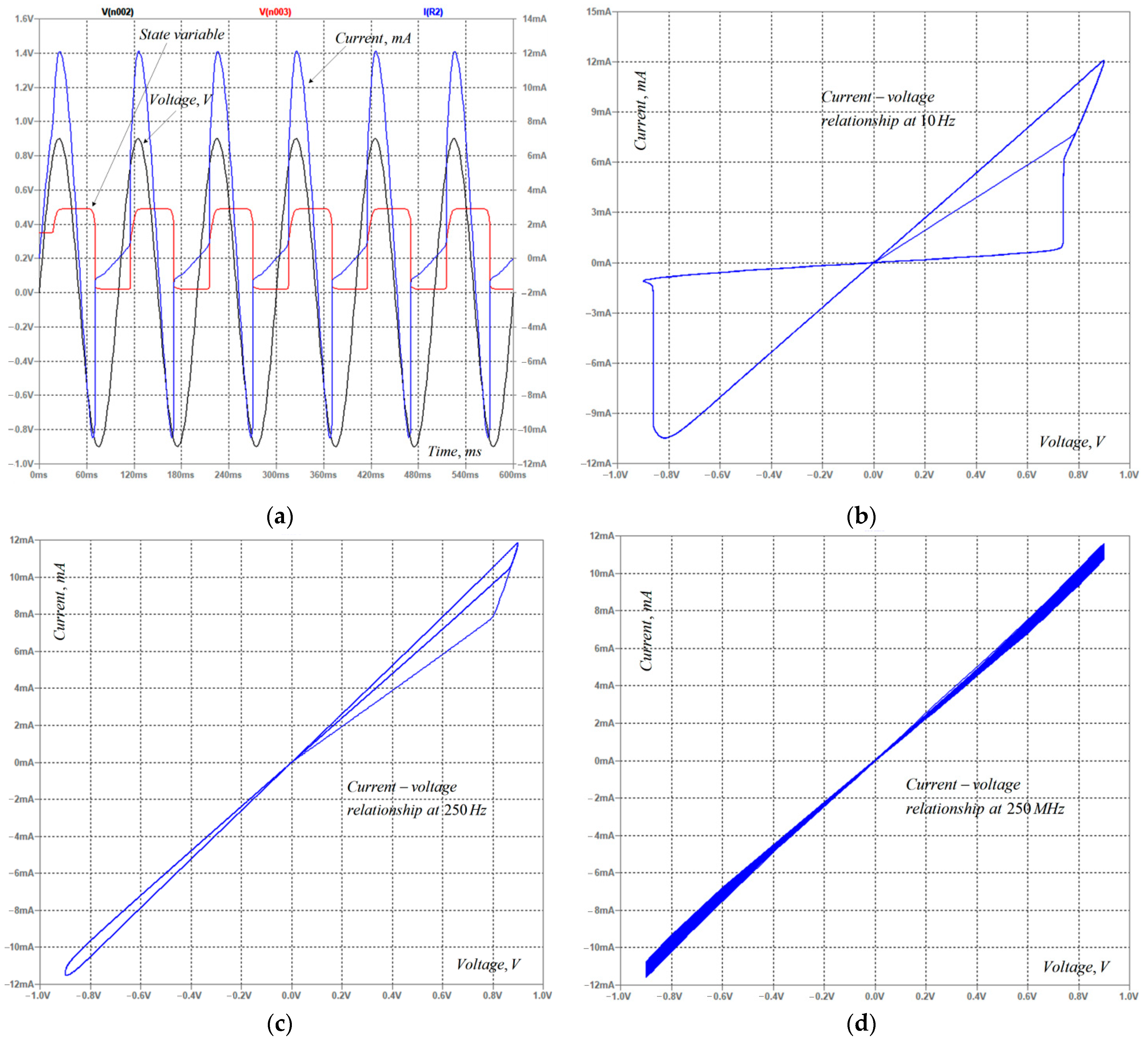
The described tantalum oxide memristor model is effectively analyzed by LTSPICE, version XVII, at various sinusoidal signals with various frequencies and amplitudes of the employed signal [
12]. The obtained time diagrams and the
i–v relationships are presented in
Figure 4a–d to illustrate the proper operation of the described memristor model [
12]. The state variable changes between 0 and 0.5. It starts from an initial value of 0.35 and, owing to the applied voltage and the generated flux linkage, their average value is decreased to a stable value of 0.25. This appropriate operation of the LTSPICE memristor model is supported by the detected decreasing of the area of the pinched current–voltage loop, while raising the frequency of the applied signal. Additional simulations at different amplitudes confirm the decrease of the area of the
i–v loop. These are two of the main fingerprints of the memristor elements [
7,
12]. The SPICE programs simulate electronic schemes and devices using initialization and iterative procedures, numerically solving the corresponding differential equations by suitable solvers [
23]. Convergence problems occur in the SPICE environment, mainly due to several reasons. Frequently, convergence issues occur in electronic circuits with several stable operating points. The limited precision of the numbers’ representation is a reason for obtaining errors and convergence issues. During the numerical integration of the respective differential equations, some models are sensitive to the errors. For example, the capacitive element
C1, which is used as an integrator, is sensitive to the derived numerical errors and it accumulates them during the simulations. The truncation errors are also related to the simulations in SPICE. Such problems are also related to the rapid rise or fall of impulse currents and voltages and steep and discontinuous characteristics of electronic components. The convergence issues are related to erroneous results and sometimes to stopping the simulation before the previously defined end time, or to the impossibility of the simulation to start normally [
23,
33]. In some cases, the decrease of the time step or the change of the tolerances of some parameters could resolve these problems. In this sense, the use of a sigmoid step-like continuous function in modeling of memristors is another way to prevent the convergence problems in LTSPICE.
The time step, used in the simulation setup, must be as low as possible, but it is related to the obtained output file and the simulation time of the respective scheme. According to the other SPICE products, LTSPICE is not sensitive to convergence issues. The computational efficiency of the considered memristor models is related to the amount of time and memory for a given iterative step in the simulation process. Conversely, the needed time for simulations is proportional to the number of elementary mathematical operations for obtaining the respective solution at a given iteration step [
23,
33].
The considered memristor model is also analyzed by rectangular pulse voltage signals with different duty cycles and amplitudes in the LTSPICE environment, and no convergence issues were observed [
12].


