
Minimisation of Failure Transients in a Fail-Safe Electro-Mechanical Actuator Employed for the Flap Movables of a High-Speed Helicopter-Plane

 ,
,  ,
,
Abstract
:1. Introduction
2. Materials and Methods
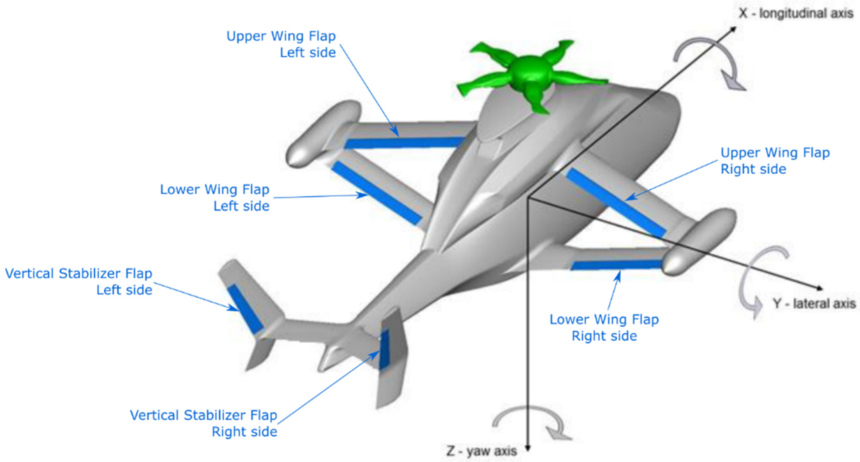
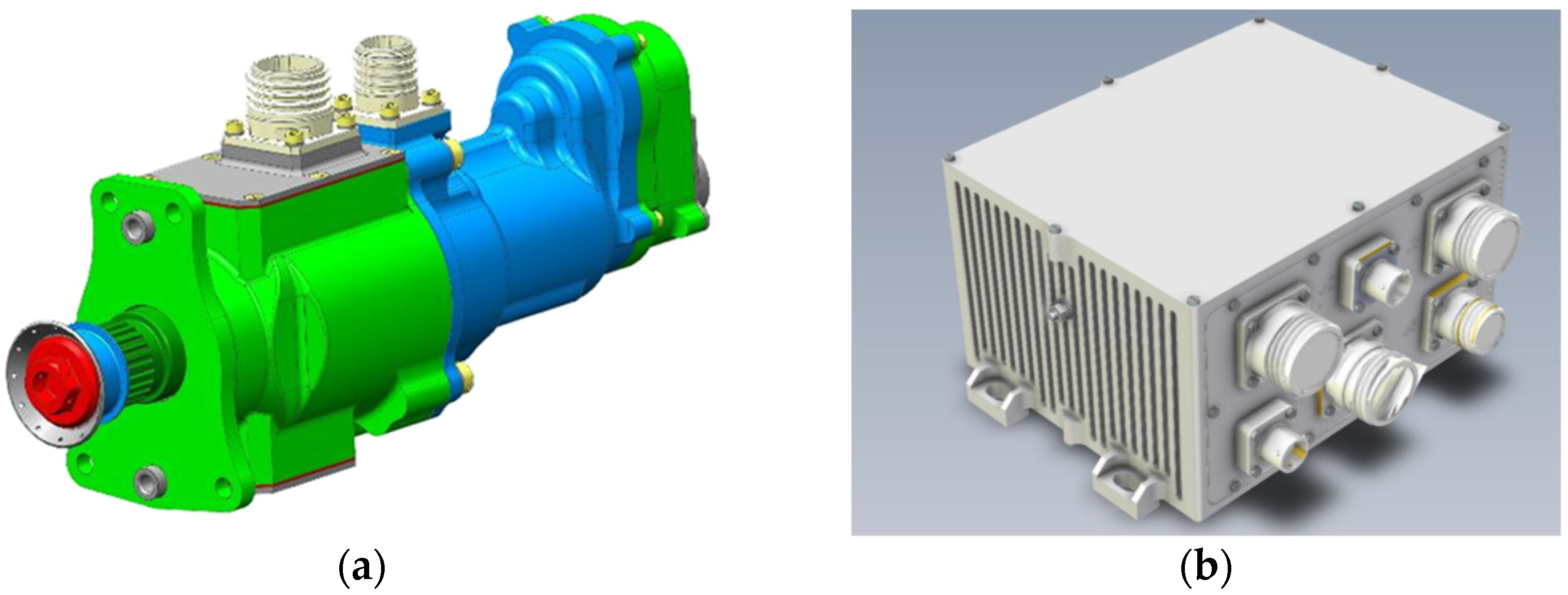
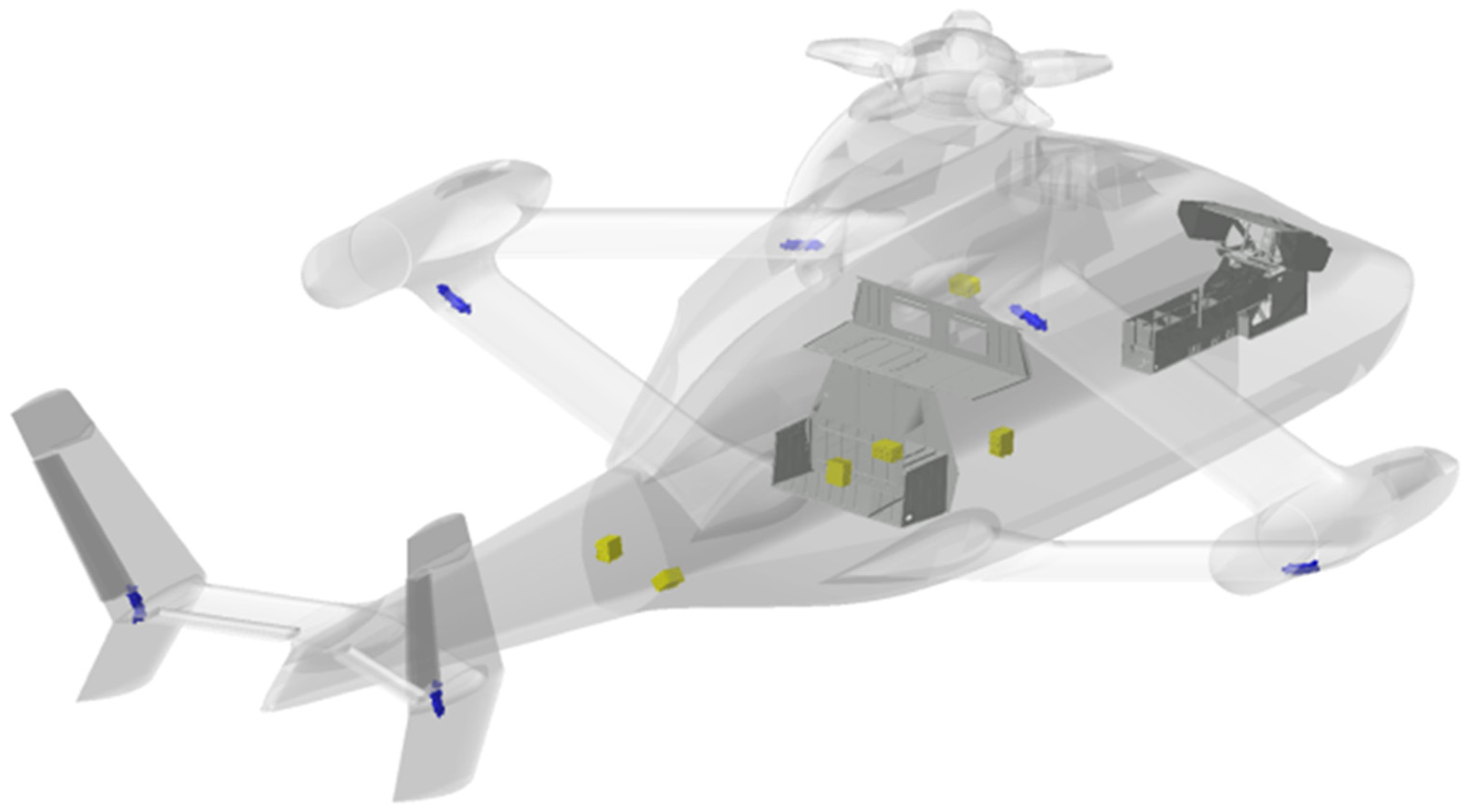
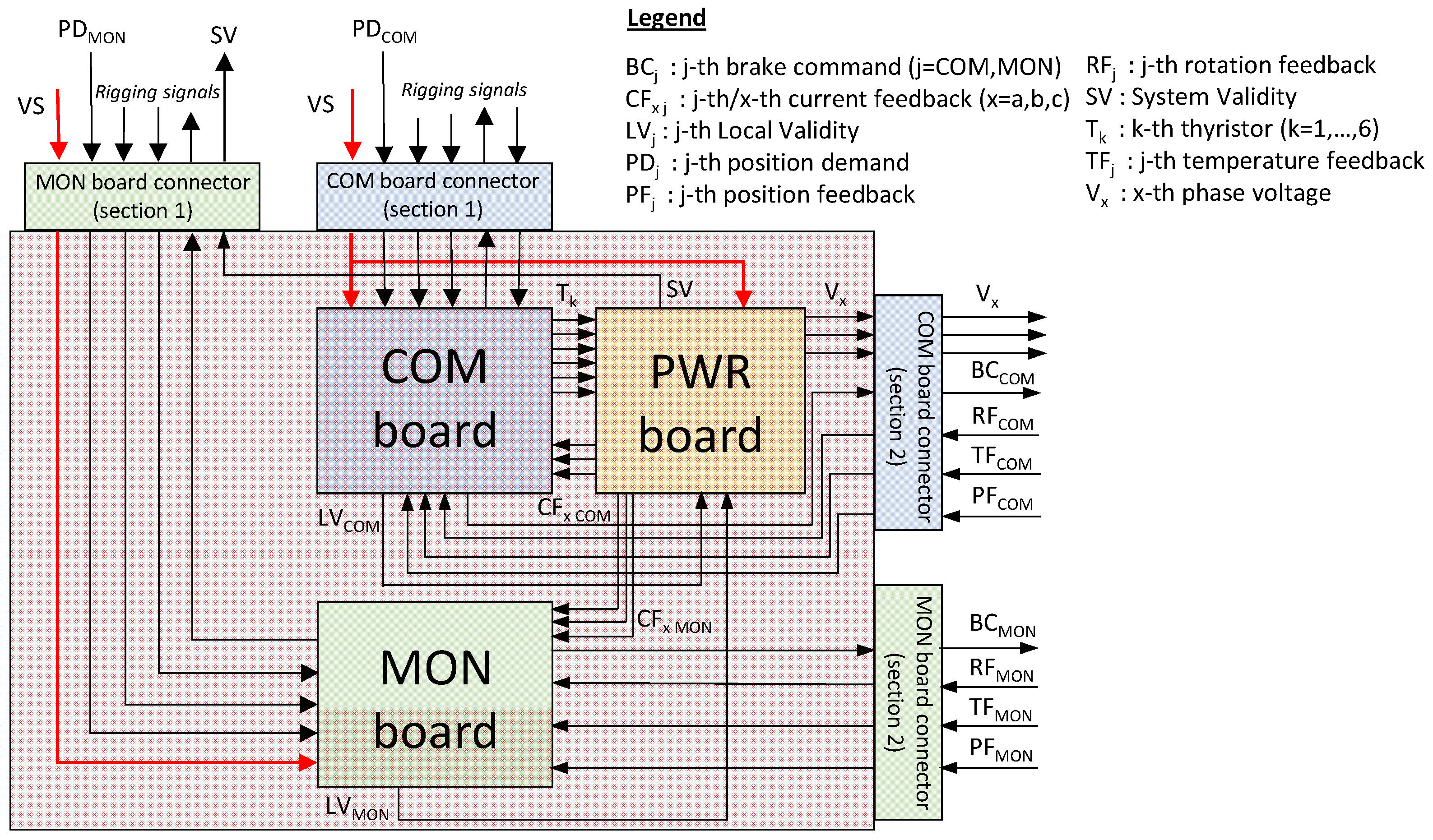
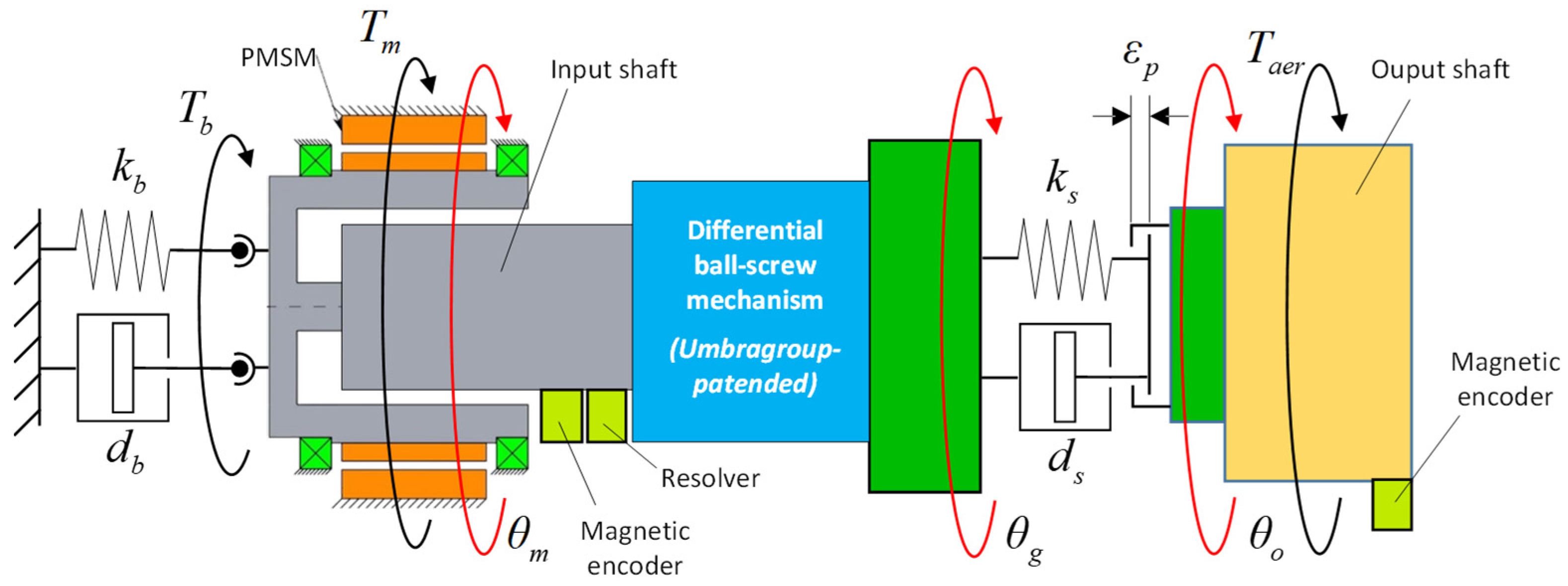
2.1. System Description
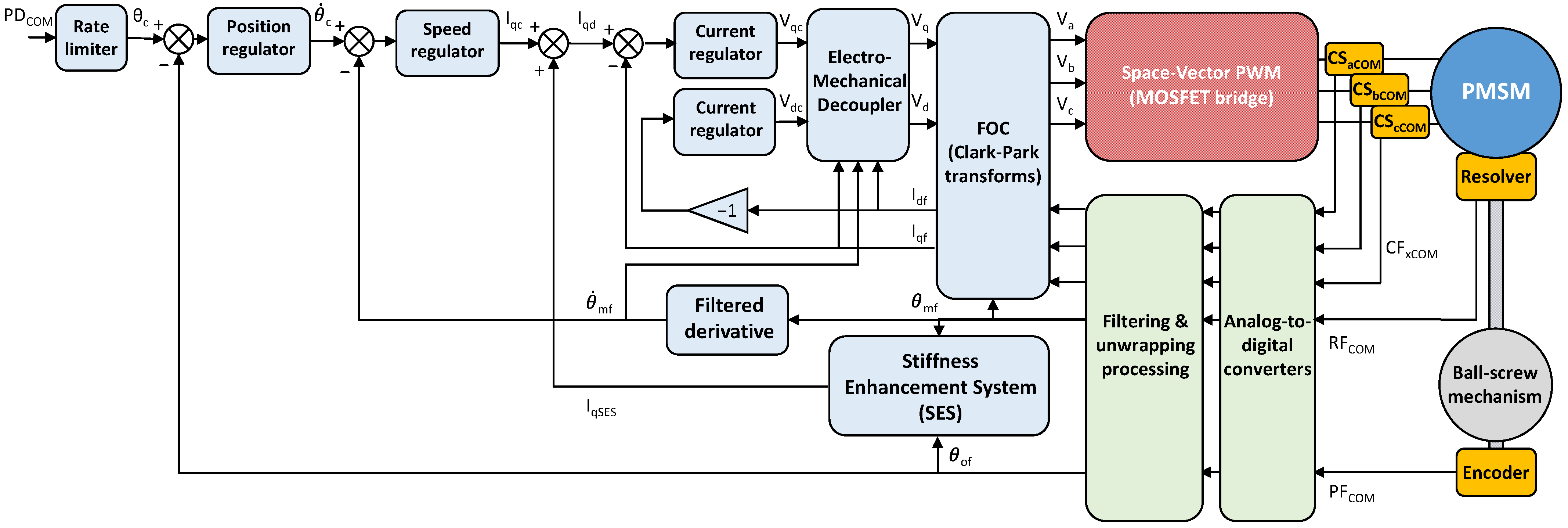
- a three-phase Permanent Magnet Synchronous Machine (PMSM) with surface-mounted magnets and sinusoidal back-electromotive forces, driven via Field-Oriented Control (FOC) technique;
- two motor rotation sensors: a resolver interfaced with the COM board and a magnetic encoder interfaced with the MON board (RFCOM and RFMON in Figure 4);
- a dual magnetic encoder for the output shaft rotation sensing, interfaced to both COM and MON boards (PFCOM and PFMON in Figure 4);
- two temperature sensors (TFCOM and TFMON in Figure 4);
- two power-off electromagnetic brakes used to block in position the EMA after a major fault detection;
- an innovative Umbragroup-patented differential ball-screw mechanism implementing the mechanical power conversion from motor to output shaft, which, if compared with conventional gearboxes, assures a high gear ratio (more than 500) with minimum backlash (less than 0.05 deg) and superior efficiency (about 95%).
2.2. Nonlinear Dynamic Modelling
- an electromechanical section, simulating
- ○
- FOC current dynamics;
- ○
- ○
- 2-degree-of-freedom mechanical transmission with equations of motions related to motor and output rotations;
- ○
- ○
- mechanical freeplay [21];
- ○
- internal stiffness dependence on output shaft position;
- an electronic section simulating the control and health-monitoring algorithms implemented by the COM and MON boards, including
- ○
- Clarke-Park transforms for the FOC technique implementation;
- ○
- sensor errors and nonlinearities (bias, noise, resolution);
- ○
- command nonlinearities (saturation, rate limiting);
- ○
- digital signal processing at 10 kHz sampling rate;
- ○
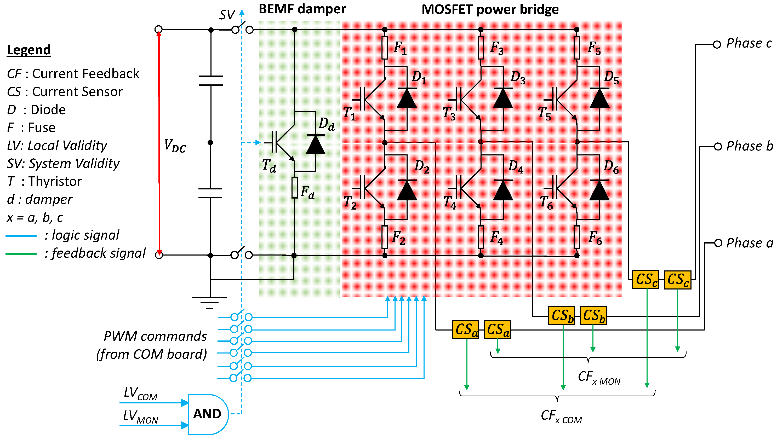
- control hardover fault simulation, implying that the voltage demands on both quadrature and direct axes suddenly assume and maintain random values, so that the EMA motion is out of control (as a worst case scenario, the quadrature voltage is set to saturation value, while the direct voltage is set to zero).
2.2.1. Electro-Mechanical Section of the Model
2.2.2. Electronic Section of the Model
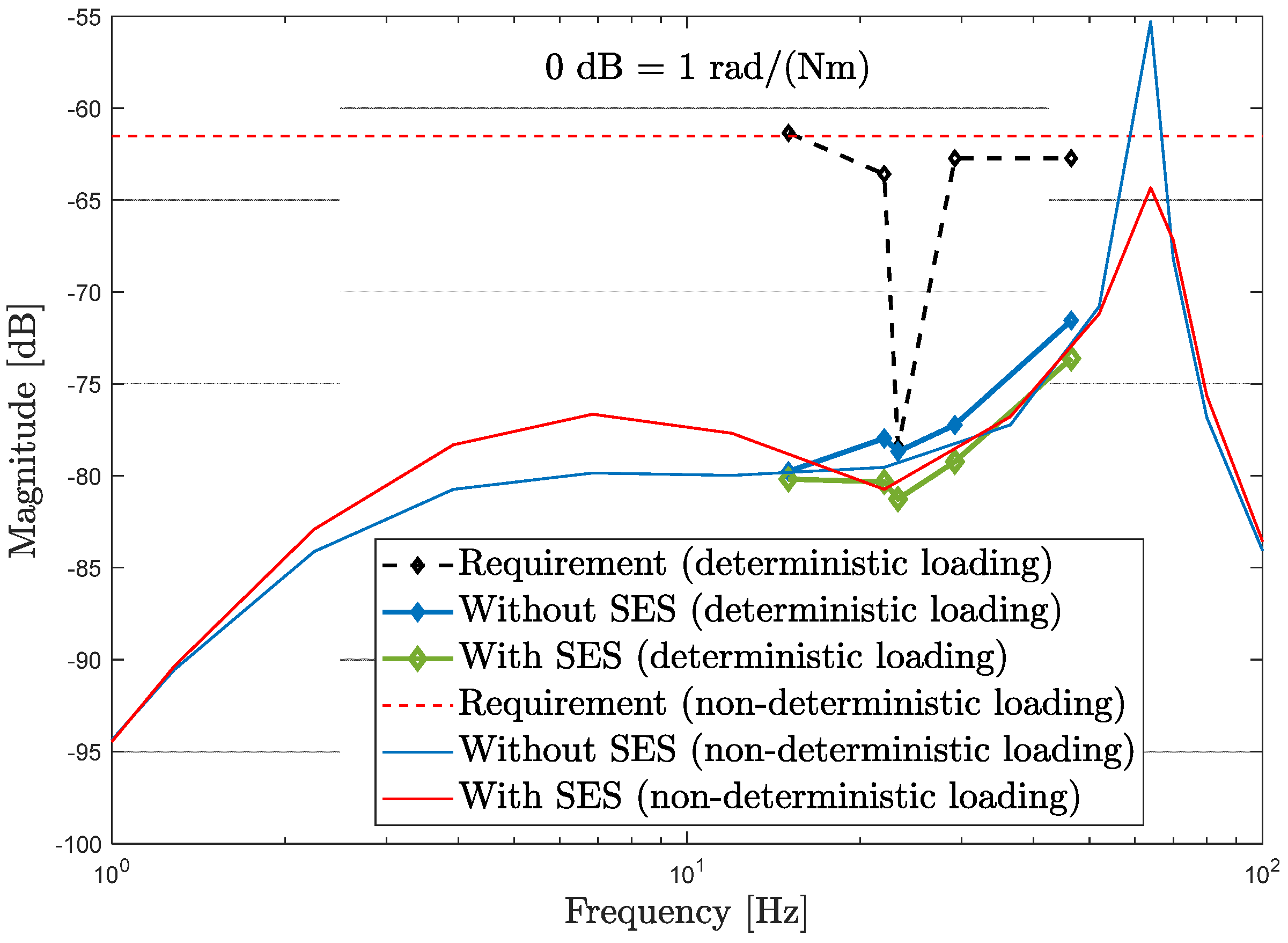
- the loop shall not affect the EMA low-frequency behaviour (maxima loads, position tracking, etc.);
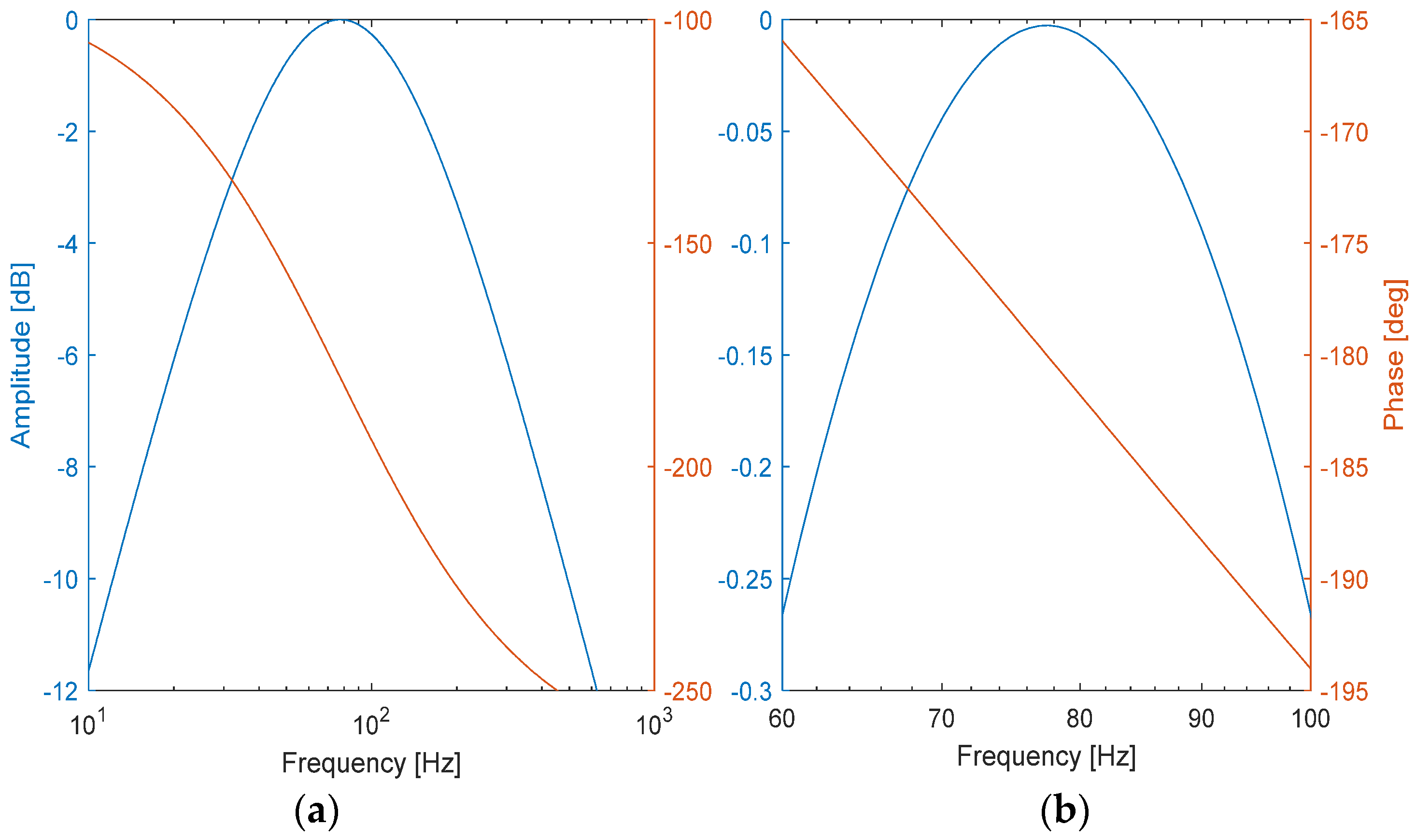
- the loop shall generate demands only in the frequency range where the first resonant pulsation of the ball-screw mechanism is located, and the compensation shall imply an increase of EMA stiffness, enhancing the disturbance rejection capabilities related to external loads.
- by tuning aSES and bSES, the phase response of the SES current demand (IqSES) with respect to torsional deformation is about −180° from 70 to 90 Hz;
- by tuning kSES, the SES current demand (IqSES) implies an effective compensation without affecting the control stability.
- over-temperature monitor, checking that the motor stator temperature does not exceed a pre-defined threshold;
- over-current monitor, checking that the quadrature current does not exceed a pre-defined threshold;
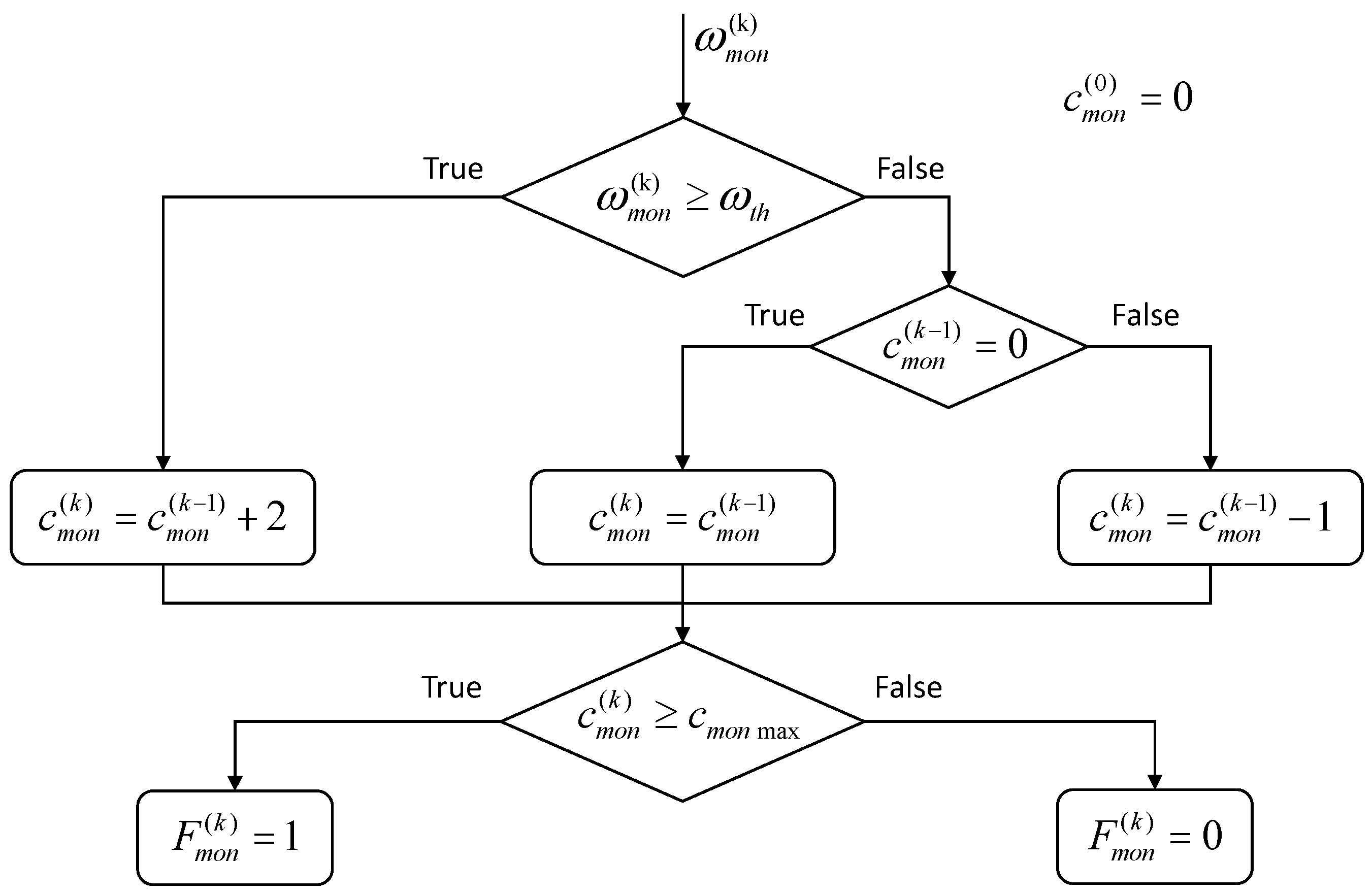
- Over-Speed Monitor (OSM), checking that the motor speed does not exceed a pre-defined threshold;
- currents consistency monitor, checking that the sum of the phase currents is lower than a pre-defined threshold;
- mechanical consistency monitor, checking that the EMA torsional deformation is lower than a pre-defined threshold;
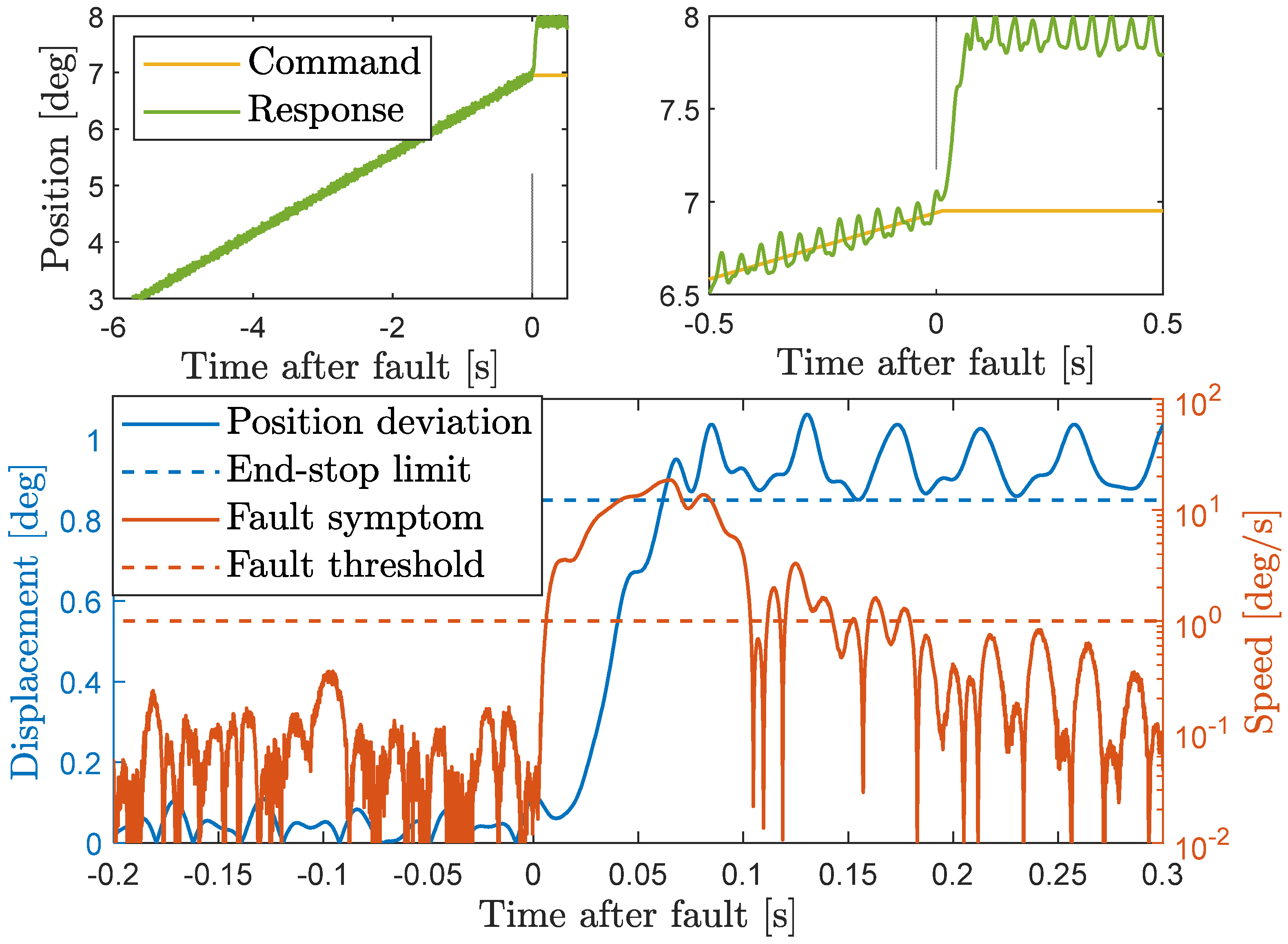
- position deviation monitor, checking that the deviation of the output position feedback from the commanded setpoint is lower than a pre-defined threshold.
2.2.3. Fault Simulation
2.3. Experimental Test Campaign for the Model Validation
- Unloaded, open-loop tests
- ○
- Test 1 (blocked motor with engaged brakes): chirp wave inputs are given as direct voltage demand, while the quadrature voltage is set to zero, aiming to identify motor phase resistance and inductance (R and L). The test is repeated at a different position of the PMSM rotor to verify that the phase inductance does not significantly depend on motor angle (assumption of the model);
- ○
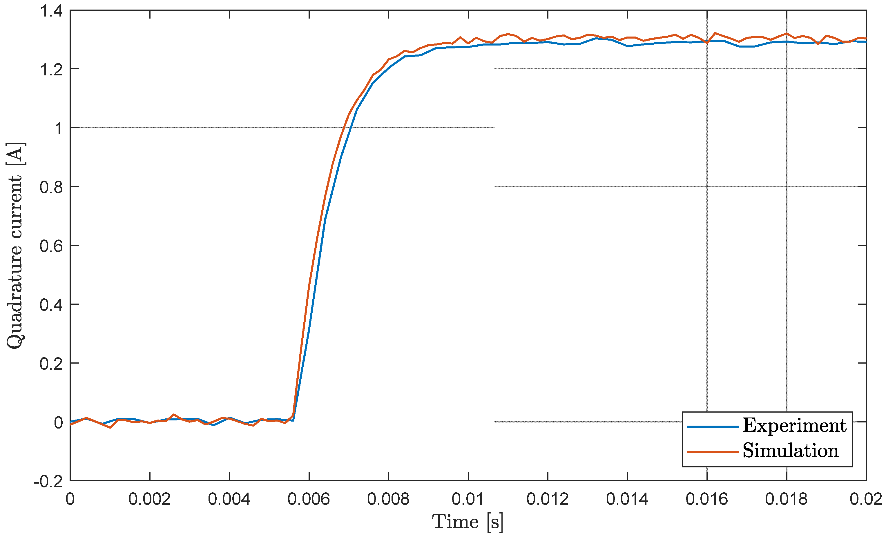
- Test 2 (blocked motor with engaged brakes): step inputs of different amplitudes are given to the quadrature voltage demand, while the direct voltage is set to zero, aiming to confirm the values of motor phase resistance and inductance. The test is repeated at different position of the PMSM rotor;
- ○
- Test 3 (free-wheeling motor with disengaged brakes and open phases): the PMSM rotor is dragged by an external motor at different speed amplitudes and the phase-to-phase BEMF is measured, aiming to identify the motor flux linkage (λm) and to eventually highlight higher harmonic components in the BEMF waveform;
- Unloaded, closed-loop tests
- ○
- Test 4 (blocked motor with engaged brakes): current loop tracking is tested by providing square-wave inputs of different amplitudes as quadrature current demand, while the direct current is set to zero, aiming to identify the damping and stiffness of the brakes (db and kb);
- ○
- Test 5 (disengaged brakes): speed loop tracking is tested, by providing square-wave inputs of different amplitudes as speed demand, aiming to identify the torque disturbance parameters (M, Thd1, nhd1, Thd2, nhd2, Thd3 and nhd3), the viscous damping coefficients (dvfm and dvfo), the parameters of the sliding friction models (Tsfm, Tsfo ωsfm and ωsfo), and the actuator inertias (Jm and Jo).
3. Results
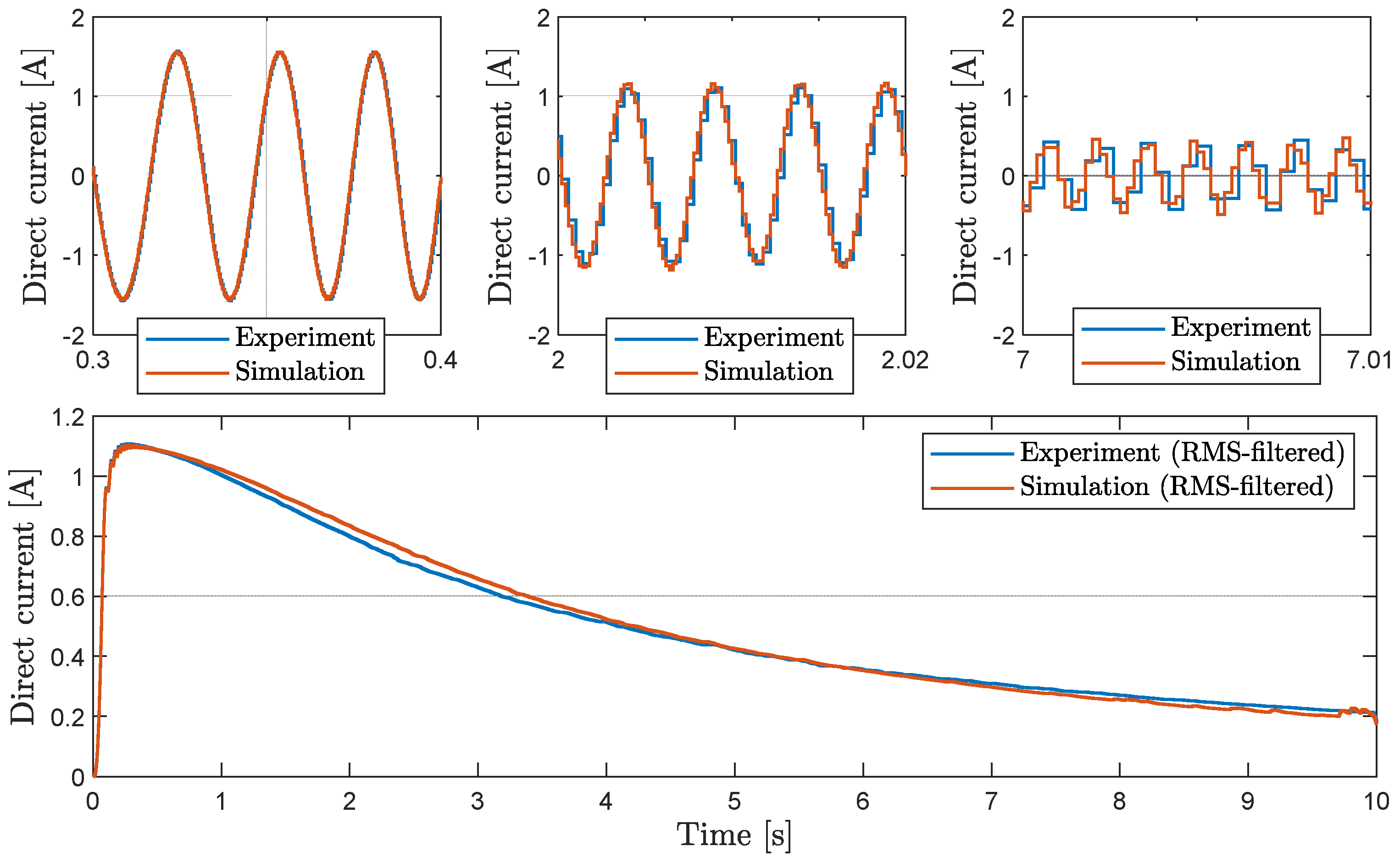
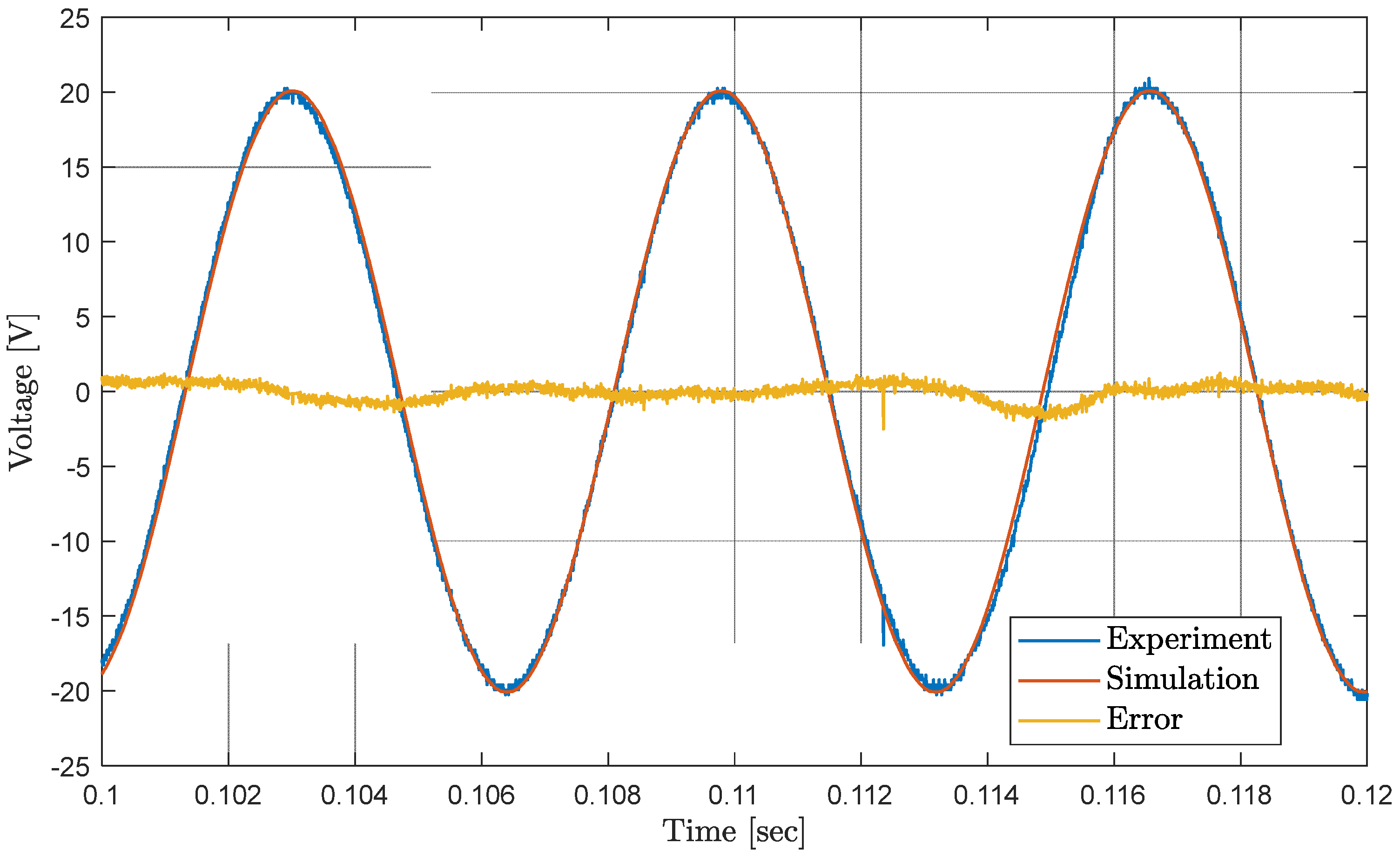
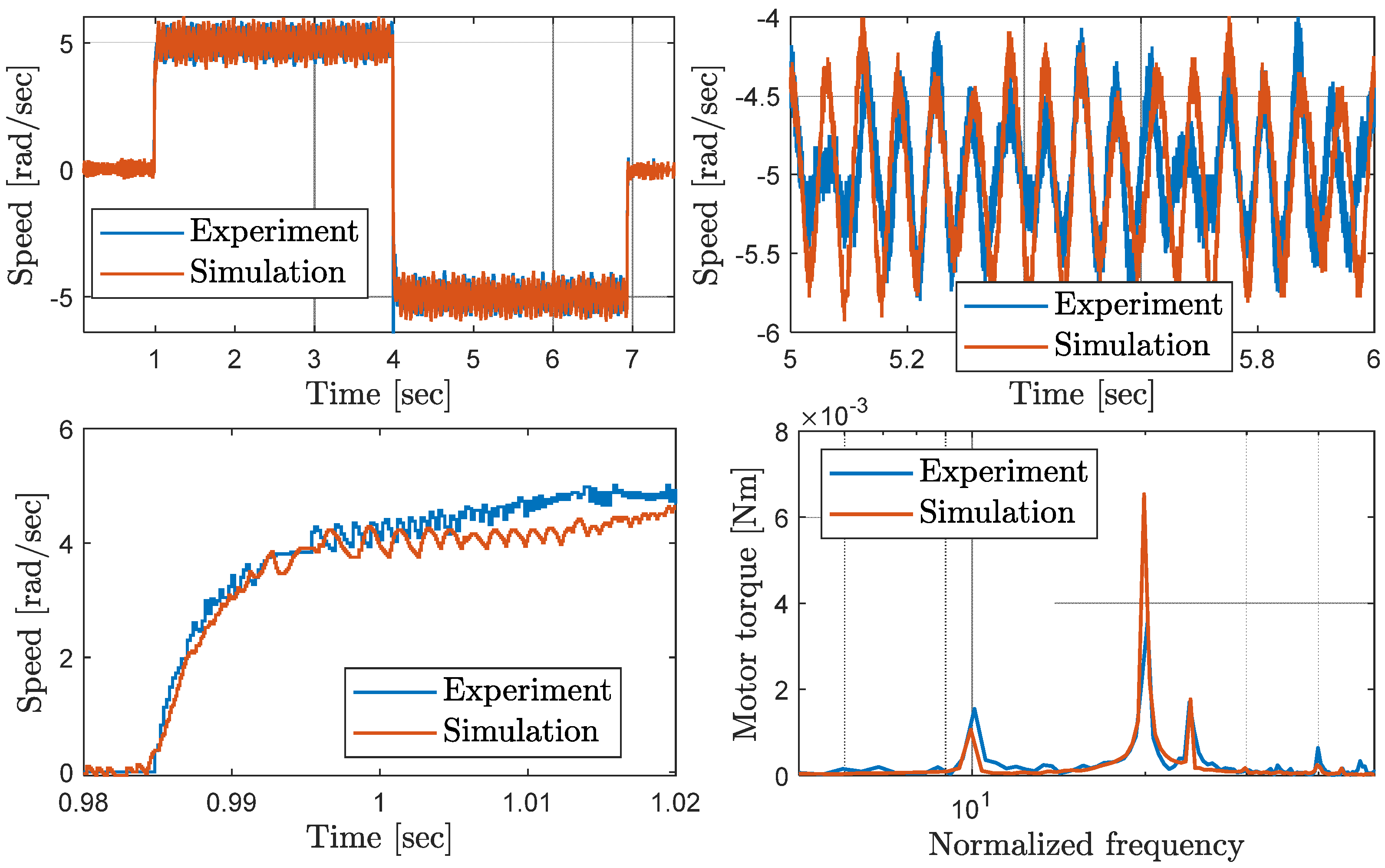
3.1. Experimental Validation of the Model
3.2. Loads Disturbance Rejection Capability
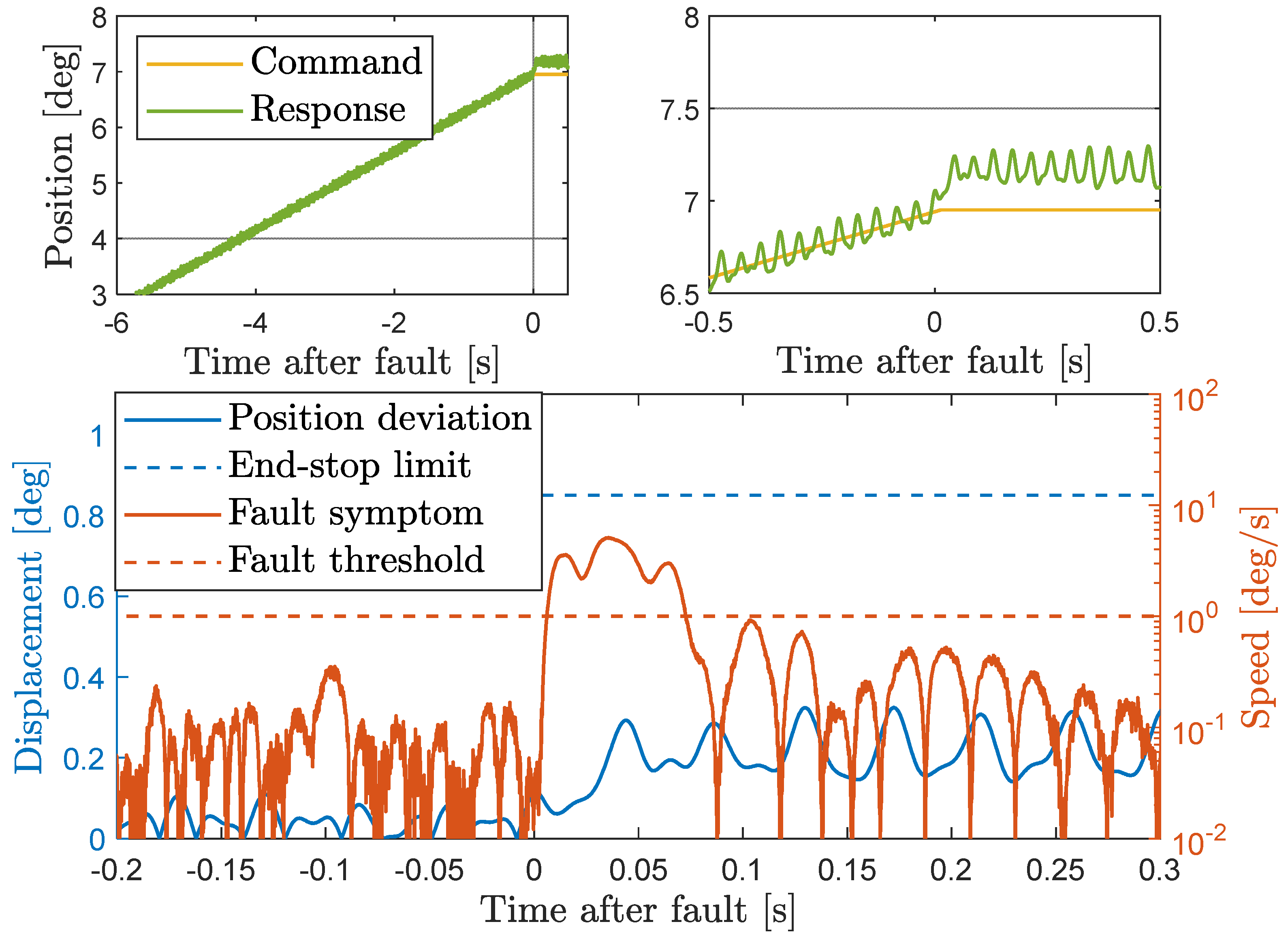
3.3. Failure Transient Analysis
- the maximum static load plus the deterministic dynamic loads defined in Table 2 are applied to the output shaft;
- the EMA is demanded to move to the maximum positive deflection (minimum stiffness);
- the control hardover fault occurs immediately after the EMA reaches the position setpoint (t = tFI = 0 s);
- the brakes activation occurs with a predefined delay from the fault detection (tFC − tFD = 51 ms, Umbragroup information).
4. Discussion
5. Conclusions
- extension of the model validation with loaded position-loop tests, aiming to:
- ○
- verify the actual location of the resonant pulsation of the ball-screw drivetrain (currently estimated via FEM analyses);
- ○
- characterise the actual disturbance rejection of external loads;
- model enhancement, by including a friction model that takes into account dependence on applied loads and temperature;
- robustness analysis of the health-monitoring performances against model parameters uncertainties.
Author Contributions
Funding
Institutional Review Board Statement
Informed Consent Statement
Data Availability Statement
Conflicts of Interest
References
- Flightpath 2050: Europe’s Vision for Aviation. Available online: https://op.europa.eu/en/publication-detail/-/publication/7d834950-1f5e-480f-ab70-ab96e4a0a0ad/language-en (accessed on 30 August 2022).
- Schäfer, A.W.; Barrett, S.R.H.; Doyme, K.; Dray, L.; Gnadt, A.R.; Self, R.; O’Sullivan, A.; Synodinos, A.; Torija, A.J. Technological, economic and environmental prospects of all-electric aircraft. Nat. Energy 2019, 4, 160–166. [Google Scholar] [CrossRef]
- Howse, M. All-electric aircraft. Power Eng. J. 2003, 17, 35–37. [Google Scholar] [CrossRef]
- Rosero, J.A.; Ortega, J.A.; Aldabas, E.; Romeral, L. Moving towards a more electric aircraft. IEEE Aerosp. Electron. Syst. Mag. 2007, 22, 3–9. [Google Scholar] [CrossRef]
- Roboam, X.; Sareni, B.; De Andrade, A. More electricity in the air: Toward optimized electrical networks embedded in more-electrical aircraft. IEEE Ind. Electron. Mag. 2012, 6, 6–17. [Google Scholar] [CrossRef]
- Madonna, V.; Giangrande, P.; Galea, M. Electrical power generation in aircraft: Review, challenges, and opportunities. IEEE Trans. Transp. Electrif. 2018, 4, 646–659. [Google Scholar] [CrossRef]
- Maré, J.-C.; Fu, J. Review on signal-by-wire and power-by-wire actuation for more electric aircraft. Chin. J. Aeronaut. 2017, 30, 857–870. [Google Scholar] [CrossRef]
- Mazzoleni, M.; Di Rito, G.; Previdi, F. Introduction. In Electro-Mechanical Actuators for the More Electric Aircraft; Advances in Industrial Control; Springer: Cham, Switzerland, 2021; Volume 2, pp. 1–44. [Google Scholar] [CrossRef]
- Maré, J.-C. Aerospace Actuators: Signal-by-Wire and Power-by-Wire; Bourrières, J.-P., Ed.; ISTE Ltd.: Washington, DC, USA; John Wiley & Sons: Hoboken, NJ, USA, 2017; Volume 2, pp. 171–217. [Google Scholar] [CrossRef]
- Di Rito, G.; Galatolo, R.; Schettini, F. Experimental and simulation study of the dynamics of an electro-mechanical landing gear actuator. In Proceedings of the 30th Congress of the International Council of the Aeronautical Sciences (ICAS), Daejeon, Korea, 25–30 September 2016. [Google Scholar]
- Giangrande, P.; Al-Timimy, A.; Galassini, A.; Papadopoulos, S.; Degano, M.; Galea, M. Design of PMSM for EMA employed in secondary flight control systems. In Proceedings of the 2018 IEEE International Conference on Electrical Systems for Aircraft, Railway, Ship Propulsion and Road Vehicles & International Transportation Electrification Conference (ESARS-ITEC), Nottingham, UK, 7–9 November 2018; pp. 1–6. [Google Scholar] [CrossRef]
- Qiao, G.; Liu, G.; Shi, Z.; Wang, Y.; Ma, S.; Lim, T.C. A review of electromechanical actuators for More/All Electric aircraft systems. Proc. Inst. Mech. Eng. Part C J. Mech. Eng. Sci. 2018, 232, 4128–4151. [Google Scholar] [CrossRef] [Green Version]
- Mazzoleni, M.; Di Rito, G.; Previdi, F. Reliability and safety of electro-mechanical actuators for aircraft applications. In Electro-Mechanical Actuators for the More Electric Aircraft; Advances in Industrial Control; Springer: Cham, Switzerland, 2021; Volume 2, pp. 45–85. [Google Scholar] [CrossRef]
- Balaban, E.; Bansal, P.; Stoelting, P.; Saxena, A.; Goebel, K.F.; Curran, S. A diagnostic approach for electro-mechanical actuators in aerospace systems. In Proceedings of the 2009 IEEE Aerospace Conference, Big Sky, MT, USA, 7–14 March 2009; pp. 1–13. [Google Scholar] [CrossRef]
- Ossmann, D.; Van der Linden, F.-L.-J. Advanced sensor fault detection and isolation for electro-mechanical flight actuators. In Proceedings of the NASA/ESA Conference on Adaptive Hardware and Systems, Montreal, QC, Canada, 15–18 June 2015; pp. 1–8. [Google Scholar]
- Ismail, M.A.A.; Balaban, E.; Spangenberg, H. Fault detection and classification for flight control electromechanical actuators. In Proceedings of the 2016 IEEE Aerospace Conference, Big Sky, MT, USA, 5–12 March 2016; pp. 1–10. [Google Scholar] [CrossRef]
- Ismail, M.A.A.; Windelberg, J. Fault detection of bearing defects for ballscrew based electro-mechanical actuators. In Proceedings of the World Congress on Condition Monitoring (WCCM), London, UK, 13–16 June 2017; pp. 1–12. [Google Scholar]
- Byington, C.; Sloelting, P.; Watson, M.; Edwards, D. A model-based approach to prognostics and health management for flight control actuators. In Proceedings of the 2004 IEEE Aerospace Conference Proceedings, Big Sky, MT, USA, 6–13 March 2004; pp. 3551–3562. [Google Scholar] [CrossRef]
- Mazzoleni, M.; Maccarana, Y.; Previdi, F.; Pispola, G.; Nardi, M.; Perni, F.; Toro, S. Development of a reliable electro-mechanical actuator for primary control surfaces in small aircrafts. In Proceedings of the 2017 IEEE International Con-ference on Advanced Intelligent Mechatronics (AIM), Munich, Germany, 3–7 July 2017; pp. 1142–1147. [Google Scholar] [CrossRef]
- Mazzoleni, M.; Previdi, F.; Scandella, M.; Pispola, G. Experimental development of a health monitoring method for electro-mechanical actuators of flight control primary surfaces in more electric aircrafts. IEEE Access 2019, 7, 153618–153634. [Google Scholar] [CrossRef]
- Di Rito, G.; Schettini, F.; Galatolo, R. Model-based prognostic health-management algorithms for the freeplay identification in electromechanical flight control actuators. In Proceedings of the 2018 IEEE International Workshop on Metrology for AeroSpace, Rome, Italy, 20–22 June 2018; pp. 340–345. [Google Scholar] [CrossRef]
- Todeschi, M.; Baxerres, L. Health Monitoring for the Flight Control EMAs. IFAC-PapersOnLine 2015, 48, 186–193. [Google Scholar] [CrossRef]
- Blanke, M.; Kinnaert, M.; Lunze, J.; Staroswiecki, M.; Schröder, J. Diagnosis and Fault-tolerant Control; Springer: Berlin, Germany, 2016. [Google Scholar] [CrossRef]
- Di Rito, G.; Galatolo, R.; Schettini, F. Self-monitoring electro-mechanical actuator for medium altitude long endurance unmanned aerial vehicle flight controls. Adv. Mech. Eng. 2016, 8, 1–12. [Google Scholar] [CrossRef] [Green Version]
- Di Rito, G.; Schettini, F. Health monitoring of electromechanical flight actuators via position-tracking predictive models. Adv. Mech. Eng. 2018, 10, 1–12. [Google Scholar] [CrossRef]
- Ferranti, L.; Wan, Y.; Keviczky, T. Fault-tolerant reference generation for model predictive control with active diagnosis of elevator jamming faults. Int. J. Robust Nonlinear Control 2018, 29, 5412–5428. [Google Scholar] [CrossRef]
- Ferranti, L.; Wan, Y.; Keviczky, T. Predictive flight control with active diagnosis and reconfiguration for actuator jamming. IFAC-PapersOnLine 2015, 48, 166–171. [Google Scholar] [CrossRef]
- Arriola, D.; Thielecke, F. Model-based design and experimental verification of a monitoring concept for an active-active electromechanical aileron actuation system. Mech. Syst. Signal Process. 2017, 94, 322–345. [Google Scholar] [CrossRef]
- Annaz, F.Y. Fundamental design concepts in multi-lane smart electromechanical actuators. Smart Mater. Struct. 2005, 14, 1227–1238. [Google Scholar] [CrossRef]
- Yu, Z.Y.; Niu, T.; Dong, H.L. A jam-tolerant electromechanical system. In Proceedings of the ACTUATOR 2018: 16th International Conference on New Actuators, Bremen, Germany, 25–27 June 2018; pp. 551–554. [Google Scholar]
- Gao, Z.; Cecati, C.; Ding, S.X. A survey of fault diagnosis and fault-tolerant techniques—Part I: Fault diagnosis with model-based and signal-based approaches. IEEE Trans. Ind. Electron. 2015, 62, 3757–3767. [Google Scholar] [CrossRef]
- Gao, Z.; Cecati, C.; Ding, S.X. A survey of fault diagnosis and fault-tolerant techniques—Part II: Fault diagnosis with knowledge-based and hybrid/active approaches. IEEE Trans. Ind. Electron. 2015, 62, 3768–3774. [Google Scholar] [CrossRef]
- Mazzoleni, M.; Di Rito, G.; Previdi, F. Fault diagnosis and condition monitoring approaches. In Electro-Mechanical Actuators for the More Electric Aircraft; Advances in Industrial Control; Springer: Cham, Switzerland, 2021; Volume 3, pp. 87–117. [Google Scholar] [CrossRef]
- Smith, M.J.; Byington, C.S.; Watson, M.J.; Bharadwaj, S.; Swerdon, G.; Goebel, K.; Balaban, E. Experimental and analytical development of health management for electro-mechanical actuators. In Proceedings of the 2009 IEEE Aerospace conference, Big Sky, MT, USA, 7–14 March 2009; pp. 1–14. [Google Scholar] [CrossRef]
- Chirico, A.J.; Kolodziej, J.R. A data-driven methodology for fault detection in electromechanical actuators. J. Dyn. Syst. Meas. Control 2014, 136, 041025. [Google Scholar] [CrossRef]
- Bodden, D.S.; Clements, N.S.; Schley, B.; Jenney, G. Seeded failure testing and analysis of an electro-mechanical actuator. In Proceedings of the 2007 IEEE Aerospace Conference, Big Sky, MT, USA, 7–14 March 2007; pp. 1–8. [Google Scholar] [CrossRef]
- Di Rito, G.; Luciano, B.; Borgarelli, N.; Nardeschi, M. Model-based condition-monitoring and jamming-tolerant control of an electro-mechanical flight actuator with differential ball screws. Actuators 2021, 10, 230. [Google Scholar] [CrossRef]
- Mazzoleni, M.; Di Rito, G.; Previdi, F. Fault diagnosis and condition monitoring of aircraft electro-mechanical actuators. In Electro-Mechanical Actuators for the More Electric Aircraft; Advances in Industrial Control; Springer: Cham, Switzerland, 2021; Volume 4, pp. 119–224. [Google Scholar] [CrossRef]
- Airbus Racer on Pace for 2022 First Flight. Available online: https://www.ainonline.com/aviation-news/business-aviation/2022-03-07/airbus-racer-pace-2022-first-flight (accessed on 30 August 2022).
- Stokkermans, T.; Veldhuis, L.; Soemarwoto, B.; Fukari, R.; Eglin, P. Breakdown of aerodynamic interactions for the lateral rotors on a compound helicopter. Aerosp. Sci. Technol. 2020, 101, 105845. [Google Scholar] [CrossRef]
- Thiemeier, J.; Öhrle, C.; Frey, F.; Keßler, M.; Krämer, E. Aerodynamics and flight mechanics analysis of Airbus Helicopters compound helicopter RACER in hover under crosswind conditions. CEAS Aeronaut. J. 2020, 11, 49–66. [Google Scholar] [CrossRef]
- Airbus Helicopters Reveals RACER High-Speed Demonstrator Configuration. Available online: https://www.airbus.com/en/newsroom/press-releases/2017-06-airbus-helicopters-reveals-racer-high-speed-demonstrator (accessed on 30 August 2022).
- Huot, R.; Eglin, P. Flight Mechanics of the RACER compound H/C. In Proceedings of the 76th Vertical Flight Society’s Annual Forum & Technology Display, Virginia Beach, VA, USA, 6–8 October 2020. [Google Scholar]
- Advanced Assembly Solutions for the Airbus RACER Joined-Wing Configuration. Available online: https://www.mobilityengineeringtech.com/component/content/article/adt/pub/features/articles/37105 (accessed on 30 August 2022).
- Airbus Begins Assembly of Racer Compound Helicopter. Available online: https://www.ainonline.com/aviation-news/general-aviation/2021-03-25/airbus-begins-assembly-racer-compound-helicopter (accessed on 30 August 2022).
- Texas Instruments. TMS570LC4357-EP ARM-Based Microcontroller. Available online: https://www.ti.com/product/TMS570LC4357-EP (accessed on 30 August 2022).
- Allegro Microsystems. Automotive Grade, Fully Integrated, Hall-Effect-Based Linear Current Sensor IC with 2.1 kVRMS Voltage Isolation and Low-Resistance Current Conductor. Available online: https://www.allegromicro.com/en/products/sense (accessed on 30 August 2022).
- Tamagawa. Brushless Resolvers (Smartsyn). Available online: https://www.tamagawa-seiki.com/products/resolver-synchro/brushless-resolver-smartsyn.html (accessed on 30 August 2022).
- Analog Devices. AD2S1210 Variable Resolution, 10-Bit to 16-Bit R/D Converter with Reference Oscillator. Available online: https://www.analog.com/en/products/ad2s1210.html (accessed on 30 August 2022).
- Analog Devices. ADA4571 Integrated AMR Angle Sensor and Signal Conditioner. Available online: https://www.analog.com/en/products/ada4571.html (accessed on 30 August 2022).
- RLS. AksIM-2™ Off-Axis Rotary Absolute Magnetic Encoder Module. Available online: https://www.rls.si/eng/aksim-2-off-axis-rotary-absolute-encoder (accessed on 30 August 2022).
- Islam, R.; Husain, I.; Fardoun, A.; Mc Laughlin, K. Permanent magnet synchronous motor magnet designs with skewing for torque ripple and cogging torque reduction. In Proceedings of the 2007 IEEE Industry Applications Annual Meeting, New Orleans, LA, USA, 23–27 September 2007; pp. 1552–1559. [Google Scholar] [CrossRef]
- Gasparin, L.; Cernigoj, A.; Markic, S.; Fiser, R. Additional cogging torque components in permanent-magnet motors due to manufacturing imperfections. IEEE Trans. Magn. 2009, 45, 1210–1213. [Google Scholar] [CrossRef]
- Dajaku, G.; Gerling, D. New methods for reducing the cogging torque and torque ripples of PMSM. In Proceedings of the 4th International Electric Drives Production Conference (EDPC), Nuremberg, Germany, 30 September–1 October 2014; pp. 1–7. [Google Scholar] [CrossRef]
- Gao, J.; Wang, G.; Liu, X.; Zhang, W.; Huang, S.; Li, H. Cogging torque reduction by elementary-cogging-unit shift for permanent magnet machines. IEEE Trans. Magn. 2017, 53, 1–5. [Google Scholar] [CrossRef]
- Olsson, H.; Åström, K.; Canudas-De-Wit, C.; Gäfvert, M.; Lischinsky, P. Friction Models and Friction Compensation. Eur. J. Control 1998, 4, 176–195. [Google Scholar] [CrossRef] [Green Version]
- Andersson, S.; Söderberg, A.; Björklund, S. Friction models for sliding dry, boundary and mixed lubricated contacts. Tribol. Int. 2007, 40, 580–587. [Google Scholar] [CrossRef]
- Dutta, C.; Tripathi, S.M. Comparison between conventional and loss d-q model of PMSM. In Proceedings of the International Conference on Emerging Trends in Electrical Electronics & Sustainable Energy Systems (ICETEESES), Sultanpur, India, 11–12 March 2016; pp. 256–260. [Google Scholar] [CrossRef]
- Zhang, C.; Tian, Z.; Dong, Y.; Zhang, S. Analysis of losses and thermal model in a surface-mounted permanent-magnet synchronous machine over a wide-voltage range of rated output power operation. In Proceedings of the IEEE Conference and Expo Transportation Electrification Asia-Pacific (ITEC Asia-Pacific), Beijing, China, 31 August–3 September 2014; pp. 1–5. [Google Scholar] [CrossRef]
- Fitzgerald, A.E.; Kingsley, C., Jr.; Umans, S.D. Electric Machinery, 6th ed.; Mc Graw-Hill: New York, NY, USA, 2003. [Google Scholar]
- Åström, K.J.; Hägglund, T. Advanced PID Control; ISA, The Instrumentation, Systems, and Automation Society: Pittsburgh, PA, USA, 2006. [Google Scholar]


| Component | Model | Range | Accuracy |
|---|---|---|---|
| Current sensor | Allegro ACS723LLCTR-10AB-T | ±10 A | 0.1 A |
| Resolver | Tamagawa TS2610N171E64 | ±π rad | 4 × 10⁻⁴ rad |
| Resolver analog-to-digital converter | Analog Devices AD2S1210 | ±π rad | 2 × 10⁻⁴ rad |
| Magnetic encoder (motor) | Analog Devices ADA4571 | ±π rad | 4 × 10⁻⁴ rad |
| Duplex magnetic encoder (output) | RLS AksIM-2 | ±0.157 rad | 1.7 × 10⁻³ rad |
| Static [Nm] | Harmonic Amplitude [Nm] | Harmonic Frequency [Hz] | Dynamic Load Definition |
|---|---|---|---|
| ±100 | 2 | 15 | Deterministic |
| 3 | 20 | ||
| 15 | 23 | ||
| 2 | 30 | ||
| 2 | 46 | ||
| 1.5 | From 1 to 100 | Non-deterministic |
| Parameter | Meaning | Value | Unit | Identification Method (See Section 2.3) |
|---|---|---|---|---|
| L | Motor phase inductance | 15 × 10−3 | H | Test 1, Test 2 |
| R | Motor phase resistance | 1.53 | ohm | Test 1, Test 2 |
| λm | Magnet flux linkage | 0.014 | N∙m/A | Test 3 |
| nd | Motor pole pairs | 10 | -- | Design |
| Jm | Motor inertia | 4 × 10⁻⁵ | kg∙m2 | Design, Test 5 |
| Tsfm | Coulomb friction on motor shaft | 0.015 | N∙m | Test 5 |
| ωsfm | Coulomb velocity on motor shaft | 0.1 | rad/s | Test 5 |
| dvfm | Viscous friction coefficient on motor shaft | 10−4 | N∙m s/rad | Test 5 |
| τg | Differential ball-screw gear ratio | 500 | -- | Design |
| θomax | Mechanical endstroke, from centred | 0.14 | rad | Design |
| ksmin | Drivetrain torsional stiffness at θo = θo max | 1.15 × 10⁴ | N∙m/rad | FEM analysis |
| γk | Parameter of the stiffness curve | 1.3 × 10⁵ | N∙m/rad3 | FEM analysis |
| ds | Drivetrain damping (1st vibration mode) | 2.6 | N∙m s/rad | FEM analysis |
| Jo | Output inertia, including flap movable | 0.06 | kg∙m2 | Design, Test 5 |
| Tsfo | Coulomb friction on output shaft | 0.5 | N∙m | Test 5 |
| ωsfo | Coulomb velocity on output shaft | 10−3 | rad/s | Test 5 |
| dvfm | Viscous friction coefficient on output shaft | 0.1 | N∙m s/rad | Test 5 |
| kb | Brakes stiffness | 150 | N∙m/rad | Test 4 |
| db | Brakes damping | 0.02 | N∙m s/rad | Test 4 |
| εp | End-life internal freeplay | 1.3 × 10⁻³ | rad | Design |
| M | Number of cogging torque harmonics | 3 | -- | Test 5 |
| Thd1 | Torque disturbance amplitude, 1st harmonic | 0.001 | N∙m | Test 5 |
| nhd1 | Torque disturbance period index, 1st harmonic | 10 | -- | Test 5 |
| Thd2 | Torque disturbance amplitude, 2nd harmonic | 0.007 | N∙m | Test 5 |
| nhd2 | Torque disturbance period index, 2nd harmonic | 20 | -- | Test 5 |
| Thd3 | Torque disturbance amplitude, 3rd harmonic | 0.002 | N∙m | Test 5 |
| nhd3 | Torque disturbance period index, 3rd harmonic | 24 | -- | Test 5 |
| Vmax | DC voltage supply | 28 | V | Design |
| Iqmax | Maximum quadrature current | 4 | A | Design |
| ωm max | Maximum motor speed | 100 | rad/s | Design |
| Parameter | Meaning | Value | Unit |
|---|---|---|---|
| Ts | Digital control sample time (all regulators) | 10−4 | s |
| Proportional gain of the position regulator | 1.58 × 10⁴ | 1/s | |
| Integral gain of the position regulator | 1.1 × 10⁵ | 1/s2 | |
| Anti-windup gain of the position regulator | 0.69 | s | |
| Saturation limit of the position regulator | 100 | rad/s | |
| Proportional gain of the speed regulator | 0.07 | A s/rad | |
| Integral gain of the speed regulator | 2 | A/rad | |
| Anti-windup gain of the speed regulator | 0.28 | rad/(A s) | |
| Saturation limit of the speed regulator | 4 | A | |
| Proportional gain of the current regulators | 2.78 | V/A | |
| Integral gain of the current regulators | 4.1 × 10³ | V/(A s) | |
| Anti-windup gain of the current regulators | 150 | A/V | |
| Saturation limit of the current regulators | 28 | V | |
| aSES | SES regulator parameter 1 | 1.02 × 10³ | rad/s |
| bSES | SES regulator parameter 2 | 2.37 × 10⁵ | rad2/s2 |
| kSES | SES regulator gain | 103 | A/(m s) |
| ωth | OSM fault symptom threshold | 0.0175 | rad/s |
| cmonmax | OSM fault counter threshold | 250 | -- |
Publisher’s Note: MDPI stays neutral with regard to jurisdictional claims in published maps and institutional affiliations. |
© 2022 by the authors. Licensee MDPI, Basel, Switzerland. This article is an open access article distributed under the terms and conditions of the Creative Commons Attribution (CC BY) license (https://creativecommons.org/licenses/by/4.0/).
Share and Cite
Di Rito, G.; Kovel, R.; Nardeschi, M.; Borgarelli, N.; Luciano, B. Minimisation of Failure Transients in a Fail-Safe Electro-Mechanical Actuator Employed for the Flap Movables of a High-Speed Helicopter-Plane. Aerospace 2022, 9, 527. https://doi.org/10.3390/aerospace9090527
Di Rito G, Kovel R, Nardeschi M, Borgarelli N, Luciano B. Minimisation of Failure Transients in a Fail-Safe Electro-Mechanical Actuator Employed for the Flap Movables of a High-Speed Helicopter-Plane. Aerospace. 2022; 9(9):527. https://doi.org/10.3390/aerospace9090527
Chicago/Turabian StyleDi Rito, Gianpietro, Romain Kovel, Marco Nardeschi, Nicola Borgarelli, and Benedetto Luciano. 2022. "Minimisation of Failure Transients in a Fail-Safe Electro-Mechanical Actuator Employed for the Flap Movables of a High-Speed Helicopter-Plane" Aerospace 9, no. 9: 527. https://doi.org/10.3390/aerospace9090527
APA StyleDi Rito, G., Kovel, R., Nardeschi, M., Borgarelli, N., & Luciano, B. (2022). Minimisation of Failure Transients in a Fail-Safe Electro-Mechanical Actuator Employed for the Flap Movables of a High-Speed Helicopter-Plane. Aerospace, 9(9), 527. https://doi.org/10.3390/aerospace9090527