Abstract
The aircraft anti-skid braking system (AABS) plays an important role in aircraft taking off, taxiing, and safe landing. In addition to the disturbances from the complex runway environment, potential component faults, such as actuators faults, can also reduce the safety and reliability of AABS. To meet the increasing performance requirements of AABS under fault and disturbance conditions, a novel reconfiguration controller based on linear active disturbance rejection control combined with deep reinforcement learning was proposed in this paper. The proposed controller treated component faults, external perturbations, and measurement noise as the total disturbances. The twin delayed deep deterministic policy gradient algorithm (TD3) was introduced to realize the parameter self-adjustments of both the extended state observer and the state error feedback law. The action space, state space, reward function, and network structure for the algorithm training were properly designed, so that the total disturbances could be estimated and compensated for more accurately. The simulation results validated the environmental adaptability and robustness of the proposed reconfiguration controller.
1. Introduction
The aircraft anti-skid braking system (AABS) is an essential airborne utilities system to ensure the safe and smooth landing of aircraft [1]. With the development of aircraft towards high speed and large tonnage, the performance requirements of AABS are increasing. Moreover, AABS is a complex system with strong nonlinearity, strong coupling, and time-varying parameters, and is sensitive to the runway environment [2]. These characteristics make AABS controller design an interesting and challenging topic.
The most widely used control method in practice is PID + PBM, which is a speed differential control law. However, it suffers from low-speed slipping and underutilization of ground bonding forces, making it difficult to meet high performance requirements. To this end, researchers have proposed many advanced control methods to improve the AABS performance, such as mixed slip deceleration PID control [3], model predictive control [4], extremum-seeking control [5], sliding mode control [6], reinforcement Q-learning control [7], and so on. Zhang et al. [8] proposed a feedback linearization controller with a prescribed performance function to ensure the transient and steady-state braking performance. Qiu et al. [9] combined backstepping dynamic surface control with an asymmetric barrier Lyapunov function to obtain a robust tracking response in the presence of disturbance and runway surface transitions. Mirzaei et al. [10] developed a fuzzy braking controller optimized by a genetic algorithm and introduced an error-based global optimization approach for fast convergence near the optimum point. The above-mentioned works provide an in-depth study on AABS control; however, the adverse effects caused by typical component faults such as actuator faults are neglected. Since most AABS are designed based on hydraulic control systems, the long hydraulic pipes create an enormous risk of air mixing with oil, and internal leakage. Without regular maintenance, it is easy to cause functional degradation or even failure, which raises many security concerns [11,12]. How to ensure the stability and the acceptable braking performance of AABS after actuator faults becomes a key issue.
In order to actually improve the safety and reliability of AABS, the fault probability can be reduced by reliability design and redundant technology on the one hand [13]. However, due to the production factors (cost/weight/technological level), the redundancy of aircraft components is so limited that the system reliability is hard to increase. On the other hand, fault-tolerant control (FTC) technology can be introduced into the AABS controller design, which is the future development direction of AABS and the key technology that needs urgent attention [14]. Reconfiguration control is a popular branch of FTC that has been widely used in many safety-critical systems, especially in aerospace engineering [15,16]. The essence of reconfiguration control is to consider the possible faults of the plant in the controller design process. When component faults occur, the fault system information is used to reconfigure the controller structure or parameters automatically [17]. In this way, the adverse effects caused by faults can be restrained or eliminated, thus realizing an asymptotically stable and acceptable performance of the closed-loop system. A number of common reconfiguration control methods can be classified as follows: adaptive control [18,19], multi-model switching control [20], sliding mode control [21], fuzzy control [22], other robust control [23], etc. In addition, the characteristics of AABS increase the difficulty of accurate modeling, and many nonlinear reconfiguration control methods are complex and relatively hard to apply in engineering. Therefore, it is crucial to design a reconfiguration controller with a clear structure, and which is model-independent, strong fault-perturbation resistant, and easy to implement.
Han retained the essence of PID control and proposed an active disturbance rejection control (ADRC) technique that requires low model accuracy and shows good control performance [24]. ADRC can estimate disturbances in internal and external systems and compensate for them [25]. Furthermore, ADRC has been widely used in FTC system design because of its obvious advantages in solving control problems of nonlinear models with uncertainty and strong disturbances [26,27,28]. Although the structure is not difficult to implement with modern digital computer technology, ADRC needs to tune a bunch of parameters which makes it hard to use in practice [29]. To overcome the difficulty, Gao proposed linear active disturbance rejection control (LADRC), which is based on linear extended state observer (LESO) and linear state error feedback (LSEF) [30,31]. The bandwidth tuning method greatly reduced the number of LADRC parameters. LADRC has been applied to solve various control problems [32,33,34].
However, it is well known that a controller with fixed parameters may not be able to maintain the acceptable (rated or degraded) performance of a fault system. For this reason, some advanced algorithms with parameter adaptive capabilities have been introduced by researchers that further improve the robustness and environmental adaptability of ADRC, such as neural networks [35,36], fuzzy logic [37,38], and the sliding mode [39,40]. With the development of artificial intelligence techniques, reinforcement learning has been applied to control science and engineering [41,42], and good results have been achieved. Yuan et al. proposed a novel online control algorithm for a thickener which is based on reinforcement learning [43]. Pang et al. studied the infinite-horizon adaptive optimal control of continuous-time linear periodic systems, using reinforcement learning techniques [44]. A Q-learning-based adaptive method for ADRC parameters was proposed by Chen et al. and has been applied to the ship course control [45].
Motivated by the above observations, in this paper, a reconfiguration control scheme via LADRC combined with deep reinforcement learning was developed for AABS which is subject to various fault perturbations. The proposed reconfiguration control method is a remarkable control strategy compared to previous methods for three reasons:
(1) AABS is extended with a new state variable, which is the sum of all unknown dynamics and disturbances not noticed in the fault-free system description. This state variable can be estimated using LESO. It indirectly simplifies the AABS modeling;
(2) Artificial intelligence technology is introduced and combined with the traditional control method to solve special control problems. By combining LADRC with the deep reinforcement learning TD3 algorithm, the selection of controller parameters is equivalent to the choice of agent actions. The parameter adaptive capabilities of LESO and LSEF are endowed through the continuous interaction between the agent and the environment, which not only eliminates the tedious manual tuning of the parameters, but also results in more accurate estimation and compensation for the adverse effects of fault perturbations;
(3) It is a data-driven robust control strategy that does not require any additional fault detection or identification (FDI) module, while the controller parameters are adaptive. Therefore, the proposed method corresponds to a novel combination of active reconfiguration control and FDI-free reconfiguration control, which makes it an interesting solution under unknown fault conditions.
2. AABS Modeling
The AABS mainly consists of the following components: aircraft fuselage, landing gear, wheels, a hydraulic servo system, a braking device, and an anti-skid braking controller. The subsystems are strongly coupled and exhibit strong nonlinearity and complexity.
Based on the actual process and objective facts of anti-skid braking, the following reasonable assumptions can be made [46]:
- (1)
- The aircraft fuselage is regarded as a rigid body with concentrated mass;
- (2)
- The gyroscopic moment generated by the engine rotor is not considered during the aircraft braking process;
- (3)
- The crosswind effect is ignored;
- (4)
- Only the longitudinal deformation of the tire is taken into account and the deformation of the ground is ignored;
- (5)
- All wheels are the same and controlled synchronously.
2.1. Aircraft Fuselage Dynamics
The force diagram of the aircraft fuselage is shown in Figure 1 and the specific parameters described in the diagram are shown in Table 1.
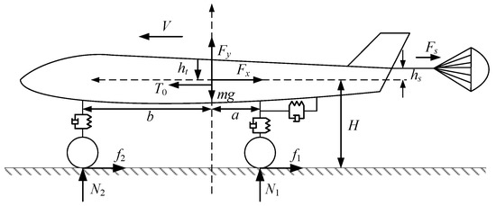
Figure 1.
Force diagram of aircraft fuselage.

Table 1.
Parameters of aircraft fuselage dynamics.
The aircraft force and torque equilibrium equations are:
According to the influence of aerodynamic characteristics, we can obtain [46]:
2.2. Landing Gear Dynamics
The main function of the landing gear is to support and buffer the aircraft, thus improving the longitudinal and vertical forces. In addition to the wheel and braking device, the struts, buffers, and torque arm are also the main components of the landing gear. In this paper, it is assumed that the stiffness of the torque arm is large enough, and the torsional freedom of the wheel with respect to the strut and the buffer is ignored, so the torque arm is not considered.
The buffer can be reasonably simplified as a mass-spring-damping system [46], and the force acting on the aircraft fuselage by the buffer can be described as:
whose parameters are shown in Table 2.

Table 2.
Parameters of the buffer.
Due to the non-rigid connection between the landing gear and the aircraft fuselage, horizontal and angular displacements are generated under the action of braking forces. However, the struts are cantilever beams, and their angular displacements are very small and negligible. Therefore, the lateral stiffness model can be expressed by the following equivalent second-order equation:
whose parameters are shown in Table 3.

Table 3.
Parameters of the landing gear lateral stiffness model.
2.3. Wheel Dynamics
The force diagram of the main wheel brake is shown in Figure 2.
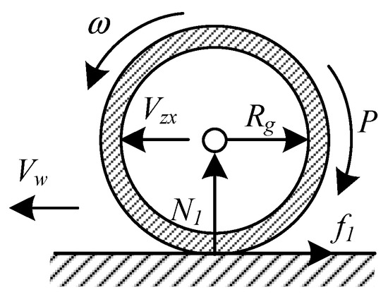
Figure 2.
Force diagram of the main wheel.
It can be seen that during the taxiing, the main wheel is subjected to a combined effect of the braking torque and the ground friction torque . Due to the effect of the lateral stiffness, there is a longitudinal axle velocity along the fuselage, which is superimposed by the aircraft velocity and the navigation vibration velocity . The dynamics equation of the main wheel is [46]:
whose parameters are shown in Table 4.

Table 4.
Parameters of the main wheel.
During the braking, the tires are subjected to the braking torque that keeps the aircraft speed always greater than the wheel speed, that is . Thus, the slip ratio is defined to represent the slip motion ratio of the wheels relative to the runway. For the main wheel, using instead of to calculate can avoid false brake release due to landing gear deformation, thus effectively reducing the landing gear walk situation [46]. The following equation is used to calculate the slip rate in this paper:
The tire–runway combination coefficient is related to many factors, including real-time runway conditions, aircraft speed, slip rate, and so on. A simple empirical formula called ‘magic formula’ developed by Pacejka [47] is widely used to calculate and can be expressed as follows:
where , , , are peak factor, stiffness factor, and curve shape factor, respectively. Table 5 lists the specific parameters for several different runway statuses [48].

Table 5.
Parameters of the runway status.
2.4. Hydraulic Servo System and Braking Device Modeling
Due to the complex structure of the hydraulic servo system, in this paper, some simplifications have been made so that only electro-hydraulic servo valves and pipes are considered. Their transfer functions are given as follows:
whose parameters are shown in Table 6.

Table 6.
Parameters of the hydraulic servo system.
It should be noted that the anti-skid braking controller should realize both braking control and anti-skid control. To this end, there is an approximately linear relationship between the brake pressure and the control current , which can be described as follows:
where .
The braking device serves to convert the brake pressure into brake torque, which is calculated as follows:
whose parameters are shown in Table 6.
The hydraulic servo system, as the actuator of AABS, is inevitably subject to some potential faults. Problems such as hydraulic oil mixing with air, internal leakage, and vibration seriously affect the efficiency of the hydraulic servo system [49]. Therefore, in this paper, the loss of efficiency (LOE) is introduced to represent a typical AABS actuator fault, which is characterized by a decrease in the actuator gain from its nominal value [26]. In the case of an actuator LOE fault, the brake pressure generated by the hydraulic servo system deviates from the commanded output expected by the controller. In other words, one instead has:
where represents the actuator actual output, and refers the LOE fault factor.
Remark 1.
LOE is equivalent to the LOE fault gain , indicates that the actuator is fault-free.
Remark 2.
Note that if the components do not always have the same characteristics as those of fault-free, it is necessary to establish the fault model. This not only provides an accurate model for the next reconfiguration on controller design, but also ensures that the adverse effects caused by fault perturbation can be effectively observed and compensated for.
Thus, Equation (11) can be rewritten as follows:
where is the actual brake torque.
Remark 3.
As can be seen from the entire modeling process described above, AABS is nonlinear and highly coupled. The actuator fault leads to a sudden jump in the model parameters with greater internal perturbation compared to the fault-free case. Meanwhile, external disturbances such as the runway environment cannot be ignored.
3. Reconfiguration Controller Design
3.1. Problem Description
Despite the aircraft having three degrees of freedom, only longitudinal taxiing is focused on in AABS. In this paper, AABS adopted the slip speed control type [48], that is, the braked wheel speed was used as the reference input, and the aircraft speed was dynamically adjusted by the AABS controller to achieve anti-skid braking. According to Section 2, the AABS longitudinal dynamics model can be rewritten as follows:
where is the controlled plant dynamics, represents the external disturbance, is an uncertain term including component faults, is the control gain, and is the system input.
Let , . Set as the system generalized total perturbation and extend it to a new system state variable, i.e., . Then the state equation of System (14) can be obtained:
where are system state variables, and .
Assumption 1.
Both the system generalized total perturbation and its differential are bounded, i.e., , where are two positive numbers.
For System (14), affected by the total perturbation, a LADRC reconfiguration controller was designed next to restrain or eliminate the adverse effects, thus realizing the asymptotic stability and acceptable performance of the closed-loop system.
3.2. LADRC Controller Design
The control schematic of the LADRC is shown in Figure 3.

Figure 3.
Control schematic of LADRC.
Firstly, the following tracking differentiator (TD) was designed:
where is the desired input, is the transition process of , is the derivative of , and and are adjusted accordingly as filter coefficients. The function is defined as follows:
We established the following form, LESO:
Selecting the suitable observer gains , LESO then enabled real-time observation of the variables in System (14) [50], i.e., , , .
Set
When can estimate without error, let LSEF be:
then the system (15) can be simplified to a double integral series structure:
Further, the bandwidth method [50] was used and we could obtain:
where is the observer bandwidth. The larger is, the smaller LESO observation errors are. However, the sensitivity of the system to noise may be increased, so the selection requires comprehensive consideration.
Similarly, according to the parameterization method and engineering experience [32], the LSEF parameters can be chosen as:
where is the controller bandwidth, is the damping ratio, and in this paper . Therefore, the parameter tuning problem of LADRC controller was simplified to the observer bandwidth and controller bandwidth configuration.
3.3. TD3 Algorithm
TD3 algorithm is an offline RL algorithm based on DDPG proposed in 2015 [51]. This approach adopted a similar method implemented in Double-DQN [52] to reduce the overestimation in function approximation, delaying the update frequency in the actor–network, and adding noises to target the actor–network to release the sensitivity and instability in DDPG. The structure of TD3 is shown in Figure 4.
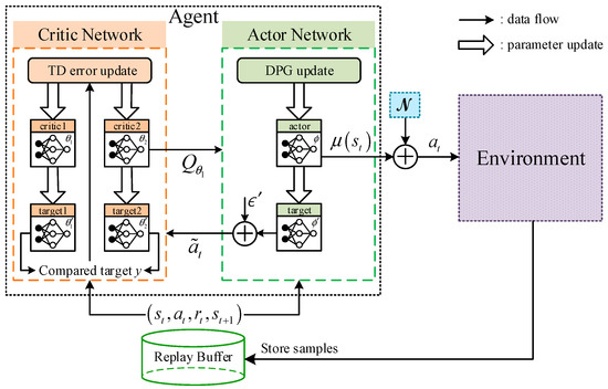
Figure 4.
Structure of TD3.
Updating the parameters of critic networks by minimizing loss:
where is the current state, is the current action, and stands for the parameterized state-action value function with parameter .
is the target value of the function , is the discount factor, and the target action is defined as:
where noise follows a clipped normal distribution clip . This implies that is a random variable with and belongs to the interval .
The inputs of the actor network are both from the critic network and the minibatch form the memory, and the output is the action given by:
where is the parameter of the actor network, and is the output form the actor network, which is a deterministic and continuous value. Noise follows the normal distribution , and is added for exploration.
Updating the parameters of the actor–network based on deterministic gradient strategy:
TD3 updates the actor–network and all three target networks every d steps periodically in order to avoid a too fast convergence. The parameters of the critic target networks and the actor–target network are updated according to:
The pseudocode of the proposed approach is given in Algorithm 1.
| Algorithm 1. TD3 |
|
3.4. TD3-LADRC Reconfiguration Controller Design
Lack of environment adaptability, poor control performance, and weak robustness are the main shortcomings of parameter-fixed controllers [36]. When a fault occurs, it may not be possible to maintain the acceptable (rated or degraded) performance of the damaged system. Motivated by the above analysis, a reconfiguration controller called TD3-LADRC is proposed in this paper, and its control schematic is shown in Figure 5.
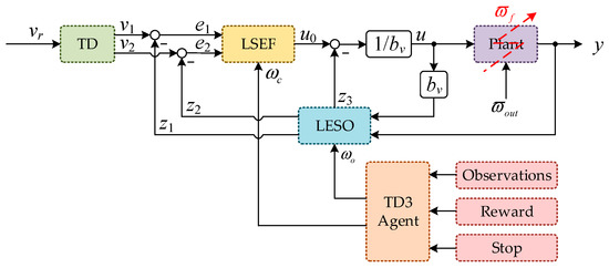
Figure 5.
Control schematic of TD3-LADRC.
The deep reinforcement learning algorithm TD3 is introduced to realize the LADRC parameters adaption. The details of each part have been described above. The selection of control parameters is treated as the agent’s action , and the response result of the control system is considered as the state, i.e., as follows:
where , and is the agent observations vector.
The range of each controller parameter is selected as follows:
The reward function plays a crucial role in the reinforcement learning algorithm. The appropriateness of the reward function design directly affects the training effect of the reinforcement learning, which in turn affects the effectiveness of the whole reconfiguration controller. According to the working characteristics of AABS, the following reward function is selected after several attempts to ensure stable and smooth braking:
The stop conditions for each training episode are as follows, and one of the three will do:
- (1)
- The aircraft speed ;
- (2)
- The error between main wheel speed and aircraft speed ;
- (3)
- Simulation time .
Remark 4.
TD3, TD, LESO, and LSEF together constitute the TD3-LADRC controller. Compared to normal LADRC, TD3-LADRC realizes the parameter adaption that makes the controller reconfigurable. The robustness and immunity are greatly improved. It can effectively compensate the adverse effects caused by the total perturbations including faults.
3.5. TD3-LESO Estimation Capability Analysis
In order to prove the stability of the whole closed-loop system, the convergence of TD3-LESO is first analyzed in conjunction with Assumption 1 [53]. Let the estimation errors of TD3-LESO be , and the estimation error equation of the observer can be obtained as:
Let , then Equation (33) can be rewritten as:
where , .
Based on Assumption 1 and Theorem 2 in Reference [54], the following theorem can be obtained:
Theorem 1.
Under the condition that is bounded, the TD3-LESO estimation errors are bounded and their upper bound decrease monotonically with the increase of the observer bandwidth .
The proof is given in the Appendix A. Thus, it is clear that there are three positive numbers , such that the state estimation error holds, i.e., the TD3-LESO estimation errors are bounded, which can effectively estimate the states of the controlled plant and the total perturbation.
3.6. Stability Analysis of Closed-loop System
The closed-loop system consisted of the control laws (19) and (20), and the controlled object (21) is:
If we defined the tracking errors as , then we could attain:
Let , then:
where , .
By solving Equation (37):
Combining Assumption 1, Theorem 1, Theorem 3, and Theorem 4 in the literature [54], the following theorem was proposed to analyze the stability of the closed-loop system:
Theorem 2.
Under the condition that the TD3-LESO estimation errors are bounded, there exists a controller bandwidth , such that the tracking error of the closed-loop system is bounded. Thus, for a bounded input, the output of the closed-loop system is bounded, i.e., the closed-loop system is BIBO-stable.
See the Appendix A for proof.
4. Simulation Results
In order to verify the reconfiguration capability and disturbance rejection capabilities of the proposed method, the corresponding simulations are carried out in this section and compared with conventional PID + PBM and LADRC.
The initial states of the aircraft are set as follows:
- (1)
- The initial speed of aircraft landing ;
- (2)
- The initial height of the center of gravity .
To prevent deep wheel slippage as well as tire blowout, the wheel speed was kept following the aircraft speed quickly at first, and the brake pressure was applied only after 1.5 s. The anti-skid brake control was considered to be over when was less than 2 m/s.
In the experiment, both the critic networks and the actor networks were realized by a fully connected neural network with three hidden layers. The number of neurons in the hidden layer was (50,25,25). The activation function of the hidden layer was selected as the ReLU function, and the activation function of the output layer of the actor network was selected as the tanh function. In addition, the parameters of the actor network and the critic network were tuned by an Adam optimizer. The remaining parameters of TD3-LADRC are shown in Table 7.

Table 7.
Parameters of TD3-LADRC.
Remark 5.
It is noted that the braking time t and braking distance x are selected as the criteria for braking efficiency, and the system stability is observed by slip rate .
The model simulation was carried out in MATLAB 2022a, and the TD3 algorithm was realized through the reinforcement learning toolbox. The simulation time was 20 s, the sampling time was 0.001 s. The training stopped when the average reward reached 12,000. The training took about 6 h to complete. The learning curves of the reward obtained by the agent for each interaction with the environment during the training process are shown in Figure 6.

Figure 6.
Learning curves.
It can be seen that at the beginning of the training, the agent was in the exploration phase and the reward obtained was relatively low. Later, the reward gradually increased, and after 40 episodes, the reward was steadily maintained at a high level and the algorithm gradually converges.
4.1. Case 1: Fault-Free and External Disturbance-Free in Dry Runway Condition
The simulation results of the dynamic braking process for different control schemes are shown in Figure 7 and Figure 8 and Table 8.
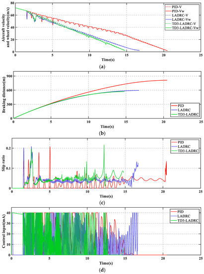
Figure 7.
(a) Aircraft velocity and wheel velocity; (b) breaking distance; (c) slip ratio; (d) control input.
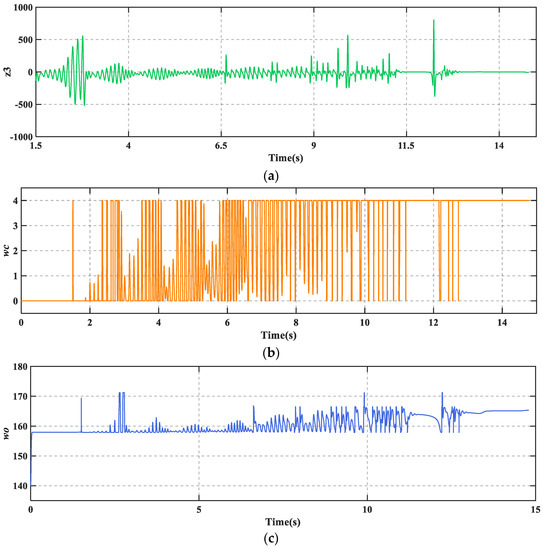
Figure 8.
(a) Extended state of TD3-LADRC; (b) controller bandwidth ; (c) controller bandwidth .

Table 8.
AABS performance index.
As can be seen from Figure 7, PID + PBM leads to numerous skids during braking, which may cause serious loss to the tires. In contrast, LADRC and TD3-LADRC not only skid less frequently, but also have shorter braking time and braking distance. Moreover, the control effect of TD3-LADRC is better than LADRC. Figure 8 shows that TD3-LADRC can dynamically tune the controller parameters to accurately observe and compensate for the total disturbances, and thus improve the AABS performance.
Remark 6.
During the braking process, it is observed that in some instants. It may not affect the stability of the whole system. On the one hand, the value of does not change the fact that is Hurwitz (see Proof of Theorem 2 for details). On the other hand, is constantly changed by the agent through a continuous interaction with the environment, and in these instants the agent considers as optimal, i.e., no anti-skid braking control leads to better braking results.
4.2. Case 2: Actuator LOE Fault in Dry Runway Condition
The fault considered here assumed a 20% actuator LOE at 5 s and escalated to 40% LOE at 10 s. The simulation results are shown in Figure 9 and Figure 10 and Table 9.
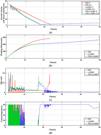
Figure 9.
(a) Aircraft velocity and wheel velocity; (b) breaking distance; (c) slip ratio; (d) control input.
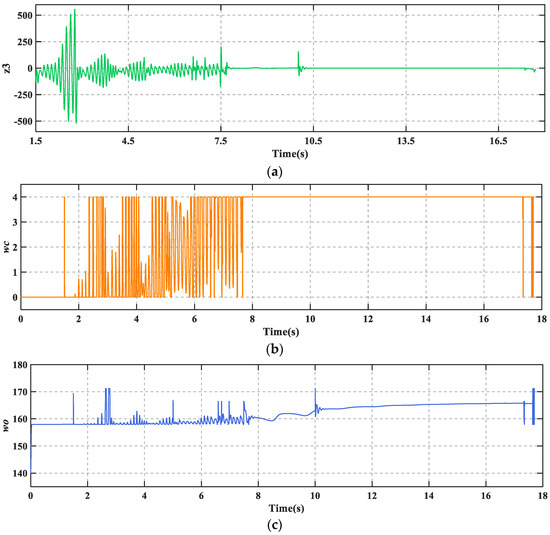
Figure 10.
(a) Extended state of TD3-LADRC; (b) controller bandwidth ; (c) controller bandwidth .

Table 9.
AABS performance index.
As can be seen in Figure 9, PID + PBM continuously performed a large braking and releasing operation under the combined effect of fault and disturbance. This makes braking much less efficient and risks dragging and flat tires. In addition, LADRC cannot brake the aircraft to a stop which is not allowed in practice. Figure 9c shows that there is a high frequency of wheel slip in the low-speed phase of the aircraft. In contrast, TD3-LADRC retains the experience gained from the agent’s prior training and continuously adjusts the controller parameters online based on the plant states, which ultimately allows the aircraft to brake smoothly. From Figure 10a, it can be seen that the total fault perturbations are estimated fast and accurately based on the adaptive LESO. Overall, TD3-LADRC not only improves the robustness and immunity of the controller in fault-perturbed conditions, but also greatly significantly improves the safety and reliability of AABS.
4.3. Case 3: Actuator LOE Fault in Mixed Runway Condition
The mixed runway structure is as follows: dry runway in the interval of 0–10 s, wet runway in the interval of 10–20 s, and snow runway after 20 s. The fault considered here assumed a 10% actuator LOE at 10 s. The simulation results are shown in Figure 11 and Figure 12 and Table 10.
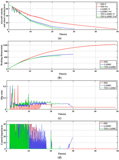
Figure 11.
(a) Aircraft velocity and wheel velocity; (b) breaking distance; (c) slip ratio; (d) control input.
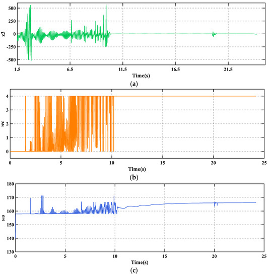
Figure 12.
(a) Extended state of TD3-LADRC; (b) controller bandwidth ; (c) controller bandwidth .

Table 10.
AABS performance index.
The deterioration of the runway conditions has resulted in a very poor tire–ground bond. It can be seen from Figure 11 that both braking time and braking distance have increased compared to the dry runway. Figure 12 shows that TD3-LADRC is still able to achieve controller parameters adaption, accurately observe the total fault perturbations, and effectively compensate for the adverse effects. The whole reconfiguration control system adapts well to runway changes. The environmental adaptability of AABS is improved.
5. Conclusions
A linear active disturbance rejection reconfiguration control scheme based on deep reinforcement learning was proposed to meet the higher performance requirements of AABS under fault-perturbed conditions. According to the composition structure and working principle, AABS mathematical model with an actuator fault factor is established. A TD3-LADRC reconfiguration controller was developed, and the parameters of LSEF and LESO were adjusted online using the TD3 algorithm. The simulation results under different conditions verified that the designed controller can effectively improve the anti-skid braking performance even under faults and perturbations, as well as different runway environments. It successfully strengthened the robustness, immunity, and environmental adaptability of the AABS, thereby improving the safety and reliability of the aircraft. However, TD3-LADRC is so complex that its control effectiveness was verified only by simulations in this paper. The combined effect caused by various uncertainties in practical applications on the robustness of the controller cannot be completely considered. Therefore, in future work, an aircraft braking hardware-in-loop experimental platform is necessary to build, consisting of the host PC, the target CPU, the anti-skid braking controller, the actuators, and the aircraft wheel. The host PC and the target CPU are the software simulation part, while the other four parts are the hardware part.
Author Contributions
Conceptualization, S.L., Z.Y. and Z.Z.; methodology, S.L., Z.Y. and Z.Z.; software, S.L. and Z.Z.; validation, S.L., Z.Y., Z.Z., R.J., T.R., Y.J., S.C. and X.Z.; formal analysis, S.L., Z.Y. and Z.Z.; investigation, S.L., Z.Y., Z.Z., R.J., T.R., Y.J., S.C. and X.Z.; resources, Z.Y., Z.Z., R.J., T.R., Y.J., S.C. and X.Z.; data curation, S.L., Z.Y., Z.Z., R.J., T.R., Y.J., S.C. and X.Z.; writing—original draft, S.L. and Z.Z.; writing—review and editing, S.L. and Z.Z.; visualization, S.L. and Z.Z.; supervision, S.L., Z.Y., Z.Z., R.J., T.R., Y.J., S.C. and X.Z.; project administration, S.L., Z.Y. and Z.Z.; funding acquisition, Z.Y., Z.Z., R.J., T.R., Y.J., S.C. and X.Z. All authors have read and agreed to the published version of the manuscript.
Funding
This research was funded by the Key Laboratory Projects of Aeronautical Science Foundation of China, grant numbers 201928052006 and 20162852031, and Postgraduate Research & Practice Innovation Program of NUAA, grant number xcxjh20210332.
Data Availability Statement
Not applicable.
Conflicts of Interest
The authors declare no conflict of interest.
Appendix A. Proof of Theorems
Proof of Theorem 1.
By solving Equation (34) we can attain:
Define as follows:
From the fact that is bounded, we have:
Because , we can attain:
Considering that is Hurwitz, there is thus a finite time so that for any , the following formula holds [54]:
Therefore, the following formula is satisfied:
Finally, we can attain:
From Equations (A3), (A4), and (A7) we can attain:
Let , for all , the following formula holds:
Form Equation (A1) we can attain:
Let , from and formulas (A8)–(A10), we can attain:
For all , the above formula holds. □
Proof of Theorem 2.
According to Equation (37) and Theorem 1, we can attain:
where , bringing in the controller bandwidth , and taking the parameters in this way ensures that is Hurwitz [54].
Define , let , then we can attain:
Consider that is Hurwitz; thus, there is a finite time so that for any , the following formula holds [54]:
Let , for any , we can attain:
Then we can attain:
From Equations (A13), (A14), and (A17) we can attain that for any :
Let , then for any :
From Equation (A12), we can attain:
From Equations (A12), (A18)–(A20), we can attain that for any :
□
References
- Li, F.; Jiao, Z. Adaptive Aircraft Anti-Skid Braking Control Based on Joint Force Model. J. Beijing Univ. Aeronaut. Astronaut. 2013, 4, 447–452. [Google Scholar]
- Jiao, Z.; Sun, D.; Shang, Y.; Liu, X.; Wu, S. A high efficiency aircraft anti-skid brake control with runway identification. Aerosp. Sci. Technol. 2019, 91, 82–95. [Google Scholar] [CrossRef]
- Chen, M.; Liu, W.; Ma, Y.; Wang, J.; Xu, F.; Wang, Y. Mixed slip-deceleration PID control of aircraft wheel braking system. IFAC-PapersOnLine 2018, 51, 160–165. [Google Scholar] [CrossRef]
- Chen, M.; Xu, F.; Liang, X.; Liu, W. MSD-based NMPC Aircraft Anti-skid Brake Control Method Considering Runway Variation. IEEE Access 2021, 9, 51793–51804. [Google Scholar] [CrossRef]
- Dinçmen, E.; Güvenç, B.A.; Acarman, T. Extremum-seeking control of ABS braking in road vehicles with lateral force improvement. IEEE Trans. Contr. Syst. Technol. 2012, 22, 230–237. [Google Scholar] [CrossRef]
- Li, F.B.; Huang, P.M.; Yang, C.H.; Liao, L.Q.; Gui, W.H. Sliding mode control design of aircraft electric brake system based on nonlinear disturbance observer. Acta Autom. Sin. 2021, 47, 2557–2569. [Google Scholar]
- Radac, M.B.; Precup, R.E. Data-driven model-free slip control of anti-lock braking systems using reinforcement Q-learning. Neurocomputing 2018, 275, 317–329. [Google Scholar] [CrossRef]
- Zhang, R.; Peng, J.; Chen, B.; Gao, K.; Yang, Y.; Huang, Z. Prescribed Performance Active Braking Control with Reference Adaptation for High-Speed Trains. Actuators 2021, 10, 313. [Google Scholar] [CrossRef]
- Qiu, Y.; Liang, X.; Dai, Z. Backstepping dynamic surface control for an anti-skid braking system. Control Eng. Pract. 2015, 42, 140–152. [Google Scholar] [CrossRef]
- Mirzaei, A.; Moallem, M.; Dehkordi, B.M.; Fahimi, B. Design of an Optimal Fuzzy Controller for Antilock Braking Systems. IEEE Trans. Veh. Technol. 2006, 55, 1725–1730. [Google Scholar] [CrossRef]
- Xiang, Y.; Jin, J. Hybrid Fault-Tolerant Flight Control System Design Against Partial Actuator Failures. IEEE Trans. Control Syst. Technol. 2012, 20, 871–886. [Google Scholar]
- Niksefat, N.; Sepehri, N. A QFT fault-tolerant control for electrohydraulic positioning systems. IEEE Trans. Control Syst. Technol. 2002, 4, 626–632. [Google Scholar] [CrossRef]
- Wang, D.Y.; Tu, Y.; Liu, C. Connotation and research of reconfigurability for spacecraft control systems: A review. Acta Autom. Sin. 2017, 43, 1687–1702. [Google Scholar]
- Han, Y.G.; Liu, Z.P.; Dong, Z.C. Research on Present Situation and Development Direction of Aircraft Anti-Skid Braking System; China Aviation Publishing & Media CO., LTD.: Xi’an, China, 2020; Volume 5, pp. 525–529. [Google Scholar]
- Calise, A.J.; Lee, S.; Sharma, M. Development of a reconfigurable flight control law for tailless aircraft. J. Guid. Control Dyn. 2001, 24, 896–902. [Google Scholar] [CrossRef]
- Yin, S.; Xiao, B.; Ding, S.X.; Zhou, D. A review on recent development of spacecraft attitude fault tolerant control system. IEEE Trans. Ind. Electron. 2016, 63, 3311–3320. [Google Scholar] [CrossRef]
- Zhang, Y.; Jin, J. Bibliographical review on reconfigurable fault-tolerant control systems. Annu. Rev. Control 2008, 32, 229–252. [Google Scholar] [CrossRef]
- Zhang, Z.; Yang, Z.; Xiong, S.; Chen, S.; Liu, S.; Zhang, X. Simple Adaptive Control-Based Reconfiguration Design of Cabin Pressure Control System. Complexity 2021, 2021, 6635571. [Google Scholar] [CrossRef]
- Chen, F.; Wu, Q.; Jiang, B.; Tao, G. A reconfiguration scheme for quadrotor helicopter via simple adaptive control and quantum logic. IEEE Trans. Ind. Electron. 2015, 62, 4328–4335. [Google Scholar] [CrossRef]
- Guo, Y.; Jiang, B. Multiple model-based adaptive reconfiguration control for actuator fault. Acta Autom. Sinica 2009, 35, 1452–1458. [Google Scholar] [CrossRef]
- Gao, Z.; Jiang, B.; Shi, P.; Qian, M.; Lin, J. Active fault tolerant control design for reusable launch vehicle using adaptive sliding mode technique. J. Frankl. Inst. 2012, 349, 1543–1560. [Google Scholar] [CrossRef]
- Shen, Q.; Jiang, B.; Cocquempot, V. Fuzzy Logic System-Based Adaptive Fault-Tolerant Control for Near-Space Vehicle Attitude Dynamics with Actuator Faults. IEEE Trans. Fuzzy Syst. 2013, 21, 289–300. [Google Scholar] [CrossRef]
- Lv, X.; Jiang, B.; Qi, R.; Zhao, J. Survey on nonlinear reconfigurable flight control. J. Syst. Eng. Electron. 2013, 24, 971–983. [Google Scholar] [CrossRef]
- Han, J. From PID to active disturbance rejection control. IEEE Trans. Ind. Electron. 2009, 56, 900–906. [Google Scholar] [CrossRef]
- Huang, Y.; Xue, W. Active disturbance rejection control: Methodology and theoretical analysis. ISA Trans. 2014, 53, 963–976. [Google Scholar] [CrossRef] [PubMed]
- Guo, Y.; Jiang, B.; Zhang, Y. A novel robust attitude control for quadrotor aircraft subject to actuator faults and wind gusts. IEEE/CAA J. Autom. Sin. 2017, 5, 292–300. [Google Scholar] [CrossRef]
- Zhang, Z.; Yang, Z.; Zhou, G.; Liu, S.; Zhou, D.; Chen, S.; Zhang, X. Adaptive Fuzzy Active-Disturbance Rejection Control-Based Reconfiguration Controller Design for Aircraft Anti-Skid Braking System. Actuators 2021, 10, 201. [Google Scholar] [CrossRef]
- Zhou, L.; Ma, L.; Wang, J. Fault tolerant control for a class of nonlinear system based on active disturbance rejection control and rbf neural networks. In Proceedings of the 2017 36th Chinese Control Conference (CCC), Dalian, China, 26–28 July 2017; IEEE: Piscataway, NJ, USA, 2017; pp. 7321–7326. [Google Scholar]
- Tan, W.; Fu, C. Linear active disturbance-rejection control: Analysis and tuning via IMC. IEEE Trans. Ind. Electron. 2015, 63, 2350–2359. [Google Scholar] [CrossRef]
- Gao, Z. Scaling and bandwidth-parameterization based controller tuning. In Proceedings of the 2003 American Control Conference, Denver, CO, USA, 4–6 June 2003; pp. 4989–4996. [Google Scholar]
- Gao, Z. Active disturbance rejection control: A paradigm shift in feedback control system design. In Proceedings of the 2006 American Control Conference, Minneapolis, MN, USA, 14–16 June 2006; IEEE: Piscataway, NJ, USA, 2006; pp. 2399–2405. [Google Scholar]
- Li, P.; Zhu, G.; Zhang, M. Linear active disturbance rejection control for servo motor systems with input delay via internal model control rules. IEEE Trans. Ind. Electron. 2020, 68, 1077–1086. [Google Scholar] [CrossRef]
- Wang, L.X.; Zhao, D.X.; Liu, F.C.; Liu, Q.; Meng, F.L. Linear active disturbance rejection control for electro-hydraulic proportional position synchronous. Control. Theory Appl. 2018, 35, 1618–1625. [Google Scholar]
- Li, J.; Qi, X.H.; Wan, H.; Xia, Y.Q. Active disturbance rejection control: Theoretical results summary and future researches. Control Theory Appl. 2017, 34, 281–295. [Google Scholar]
- Qiao, G.L.; Tong, C.N.; Sun, Y.K. Study on Mould Level and Casting Speed Coordination Control Based on ADRC with DRNN Optimization. Acta Autom. Sin. 2007, 33, 641–648. [Google Scholar]
- Qi, X.H.; Li, J.; Han, S.T. Adaptive active disturbance rejection control and its simulation based on BP neural network. Acta Armamentarii 2013, 34, 776–782. [Google Scholar]
- Sun, K.; Xu, Z.L.; Gai, K.; Zou, J.Y.; Dou, R.Z. Novel Position Controller of Pmsm Servo System Based on Active-disturbance Rejection Controller. Proc. Chin. Soc. Electr. Eng. 2007, 27, 43–46. [Google Scholar]
- Dou, J.X.; Kong, X.X.; Wen, B.C. Attitude fuzzy active disturbance rejection controller design of quadrotor UAV and its stability analysis. J. Chin. Inert. Technol. 2015, 23, 824–830. [Google Scholar]
- Zhao, X.; Wu, C. Current deviation decoupling control based on sliding mode active disturbance rejection for PMLSM. Opt. Precis. Eng. 2022, 30, 431–441. [Google Scholar] [CrossRef]
- Li, B.; Zeng, L.; Zhang, P.; Zhu, Z. Sliding mode active disturbance rejection decoupling control for active magnetic bearings. Electr. Mach. Control. 2021, 7, 129–138. [Google Scholar]
- Buşoniu, L.; de Bruin, T.; Tolić, D.; Kober, J.; Palunko, I. Reinforcement learning for control: Performance, stability, and deep approximators. Annu. Rev. Control 2018, 46, 8–28. [Google Scholar] [CrossRef]
- Nian, R.; Liu, J.; Huang, B. A review on reinforcement learning: Introduction and applications in industrial process control. Comput. Chem. Eng. 2020, 139, 106886. [Google Scholar] [CrossRef]
- Yuan, Z.L.; He, R.Z.; Yao, C.; Li, J.; Ban, X.J. Online reinforcement learning control algorithm for concentration of thickener underflow. Acta Autom. Sin. 2021, 47, 1558–1571. [Google Scholar]
- Pang, B.; Jiang, Z.P.; Mareels, I. Reinforcement learning for adaptive optimal control of continuous-time linear periodic systems. Automatica 2020, 118, 109035. [Google Scholar] [CrossRef]
- Chen, Z.; Qin, B.; Sun, M.; Sun, Q. Q-Learning-based parameters adaptive algorithm for active disturbance rejection control and its application to ship course control. Neurocomputing 2020, 408, 51–63. [Google Scholar] [CrossRef]
- Zou, M.Y. Design and Simulation Research on New Control Law of Aircraft Anti-skid Braking System. Master’s Thesis, Northwestern Polytechnical University, Xi’an, China, 2005. [Google Scholar]
- Pacejka, H.B.; Bakker, E. The magic formula tyre model. Veh. Syst. Dyn. 1992, 21, 1–18. [Google Scholar] [CrossRef]
- Wang, J.S. Nonlinear Control Theory and its Application to Aircraft Antiskid Brake Systems. Master’s Thesis, Northwestern Polytechnical University, Xi’an, China, 2001. [Google Scholar]
- Jiao, Z.; Liu, X.; Shang, Y.; Huang, C. An integrated self-energized brake system for aircrafts based on a switching valve control. Aerosp. Sci. Technol. 2017, 60, 20–30. [Google Scholar] [CrossRef]
- Yuan, D.; Ma, X.J.; Zeng, Q.H.; Qiu, X. Research on frequency-band characteristics and parameters configuration of linear active disturbance rejection control for second-order systems. Control Theory Appl. 2013, 30, 1630–1640. [Google Scholar]
- Lillicrap, T.P.; Hunt, J.J.; Pritzel, A.; Heess, N.; Erez, T.; Tassa, Y.; Silver, D.; Wierstra, D. Continuous control with deep reinforcement learning. arXiv 2015, arXiv:1509.02971. [Google Scholar]
- Fujimoto, S.; Hoof, H.; Meger, D. Addressing function approximation error in actor-critic methods. In Proceedings of the 35th International Conference on Machine Learning, Stockholm, Sweden, 10–15 July 2018; pp. 1587–1596. [Google Scholar]
- Chen, Z.Q.; Sun, M.W.; Yang, R.G. On the Stability of Linear Active Disturbance Rejection Control. Acta Autom. Sin. 2013, 39, 574–580. [Google Scholar] [CrossRef]
- Zheng, Q.; Gao, L.Q.; Gao, Z. On stability analysis of active disturbance rejection control for nonlinear time-varying plants with unknown dynamics. In Proceedings of the 2007 46th IEEE conference on decision and control, New Orleans, LA, USA, 12–14 December 2007; IEEE: Piscataway, NJ, USA, 2007; pp. 3501–3506. [Google Scholar]
Publisher’s Note: MDPI stays neutral with regard to jurisdictional claims in published maps and institutional affiliations. |
© 2022 by the authors. Licensee MDPI, Basel, Switzerland. This article is an open access article distributed under the terms and conditions of the Creative Commons Attribution (CC BY) license (https://creativecommons.org/licenses/by/4.0/).