Article

Improved Delayed Detached-Eddy Investigations on the Flow Control of the Leading-Edge Flat Spoiler of the Cavity in the Low-Aspect-Ratio Aircraft

Computational Aerodynamics Institute, China Aerodynamics Research and Development Center, Mianyang 621000, China
*
Authors to whom correspondence should be addressed.
Aerospace 2022, 9(9), 526; https://doi.org/10.3390/aerospace9090526
Submission received: 12 July 2022 / Revised: 19 August 2022 / Accepted: 11 September 2022 / Published: 19 September 2022
(This article belongs to the Section Aeronautics)

Abstract

:
The internal weapon bay is widely used in modern aircraft; however, because the unsteady flows of the cavity would cause dangerous store separation and intense aerodynamic noise, the leading-edge spoiler is an easy and efficient passive flow-control method. The flow control of the leading-edge flat spoiler before the cavity of a low-aspect-ratio flying-wing aircraft is investigated based on numerical simulation. Numerical results show that the leading-edge flat spoiler completely changes the cavity flow; it obviously lifts up the shear layer and reduces the pressure inside the cavity. For the store separation from the weapon bay, the leading-edge flat spoiler is a very good passive flow-control method that curbs the nose-up trend of the store and produces a safe and stable store separation. Besides, the leading-edge spoiler reduces the noise in the rear of the cavity (max 8.2 dB), but increases the noise in the middle of the cavity (max 11.3 dB). In addition, the leading-edge spoiler brings in a large drag increase to the aircraft (39.41% when the height of spoiler is 0.2 m), which would affect the operational stability of the aircraft. The results of this paper could provide a reference for the flow control of weapon bays and the design of aircraft.

1. Introduction

The internal weapon bay is widely used in modern aircraft due to its many advantages. First, loading the missiles into the internal weapon bay could effectively reduce the drag of aircraft. Second, the internal weapon bay improves the maneuverability of the aircraft and avoids severe aerodynamic heating that missiles would suffer under supersonic conditions. Besides, the internal weapon bay would significantly reduce the cross-sectional area of radar scattering and improve the stealth performance of aircraft. As shown in Figure 1, many modern aircraft, such as B-2 and F-22, use internal weapon bays, and the internal weapon bay is an inevitable choice in aircraft design in the future.
Although cavity flows have been under research for many years, there are still many technical problems to be solved regarding the weapon bay. When the cavity is exposed to high-speed free-stream flow, the unsteady flow inside the cavity would cause dangerous store separation and intense aerodynamic noise [1]. On the one hand, there is usually a high pressure on the rear wall and bottom floor and a low pressure at the front wall, which makes the store produce a nose-up pitching moment. The store is in a nose-up attitude during separation, which also produces large lift force. As a result, in some cases the store would collide with the aircraft, and in other cases, the store would be out of control due to excessive nose-up attitude. For example, Figure 2 shows a wind tunnel test of a store separation from a weapon bay [2]. The nose-up pitching moment places the store in a nose-up attitude, and as a result, the store collides with the cavity, which is a typical case of the dangerous store separation caused by cavity flow. On the other hand, the unsteady flows inside the cavity would cause strong aerodynamic noise; the sound-pressure level (SPL) at the rear wall and bottom floor could be 170–180 dB in supersonic flows [3,4]. Such a high acoustic-noise level could cause damages to the structure and internal devices of the aircraft.
Store separation and aerodynamic noise are two difficult issues in the research of the internal weapon bay, and many researchers have investigated flow-control methods. Based on whether there is a need for external energy input, the flow-control methods can be roughly categorized as active and passive flow-control methods [5,6,7]. Active flow-control methods, such as jet flow and plasma technology, have the advantages of wide application range and easy adaptation based on the flight environments [8,9]. However, active flow control requires a large external energy input, which greatly limits its engineering applications. Passive flow-control methods, such as leading-edge spoilers and trailing-edge ramps, change the flow structures by modifying the geometric shape of the cavity [10]. Passive flow control is a more ideal choice for real aircraft because it avoids further system complexity.
Many researchers have investigated passive flow-control methods for the cavity (Figure 3). In most situations, leading-edge modifications can suppress the aerodynamic noise. Omer and Chen studied noise suppression of the cavity with several leading-edge spoilers and analyzed the frequency and sound-pressure level in the cavity [11,12]. Shaw researched the flow characteristics of a simplified cavity of F-111 aircraft, and the results showed that the leading-edge sawtooth spoiler could effectively reduce the aerodynamic noise [13]. Ukeiley compared the flow control of a cylindrical spoiler and a traditional spoiler and found that the mechanisms of noise suppression are different [14]. Saddington et al. investigated the flow control of many passive leading-edge methods, and the results showed that the distribution and shape of the rod spoiler are important factors affecting the noise-suppression level [15,16,17]. Gai and Luo studied the influence of leading-edge spoilers on the flow characteristics of supersonic cavities with a wind-tunnel experiment and numerical simulation, and the results showed that the leading-edge sawtooth spoiler could also reduce the noise in supersonic conditions [18,19]. However, not all leading-edge spoilers can reduce the aerodynamic noise inside the cavity. Schmit compared leading-edge spoiler-flow control under subsonic and supersonic conditions based on wind-tunnel experiments, and the results showed that some spoilers could reduce the aerodynamic noise in subsonic flows, but increased the aerodynamic noise in supersonic flows [20]. Zhang studied the flow control of leading-edge modifications with a cavity of a real aircraft based on both wind-tunnel experiments and numerical simulation, and the results showed that some typical passive flow-control methods, such as leading-edge sawtooth, leading-edge column, and flat spoilers, could not suppress the aerodynamic noise; on the contrary, the flows became more chaotic and the sound-pressure level increased [21]. As for the store separation, there are few studies on the flow control of store releasing from a cavity [22,23].
In summary, although there are many studies on cavity noise, the studies on the flow control of store separation are very limited. However, in fact, the main purpose of the internal weapon bay is to drop stores. Besides, the majority of previous studies focus on a simple regular rectangular cavity without the aircraft, and studies about the cavity in a real aircraft are very limited; however, the flow characteristics of real aircraft are more complex. Furthermore, most of the studies usually investigate the store separation or the aerodynamic noise as a single isolated issue. However, in fact, the passive flow-control method modifies the configuration of the aircraft, which not only affects the flow characteristics and aerodynamic noise inside the cavity, but also affects the store separation and aerodynamic characteristics of the aircraft. Therefore, it is necessary to study the comprehensive effects of the leading-edge spoiler on the cavity of a real aircraft, including the flow characteristics, aerodynamic characteristics, and the flow control of both store separation and aerodynamic noise.
The flow control of the leading-edge flat spoiler before the cavity of a low-aspect-ratio flying-wing aircraft is investigated based on numerical simulation in this paper. The improved delayed detached eddy simulation (IDDES) method, HLLE++ numerical scheme, dynamic hybrid overset mesh method, and mesh adaptation method are utilized to ensure the numerical accuracy. The comprehensive effects of the leading-edge flat spoiler to the flow characteristics, aerodynamic characteristics, and the flow control of both store separation and aerodynamic noise are discussed in detail. The results of this paper could provide a reference for the flow control of weapon bays and the design of aircraft. The rest of the paper is organized as follows: The research model is described in Section 2. The numerical method and validation are presented in Section 3. The results of the flow control of the leading-edge flat spoiler are presented and discussed in detail in Section 4. Finally, conclusions are presented in Section 5.

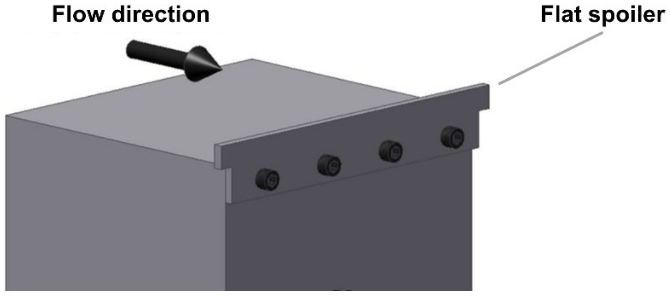
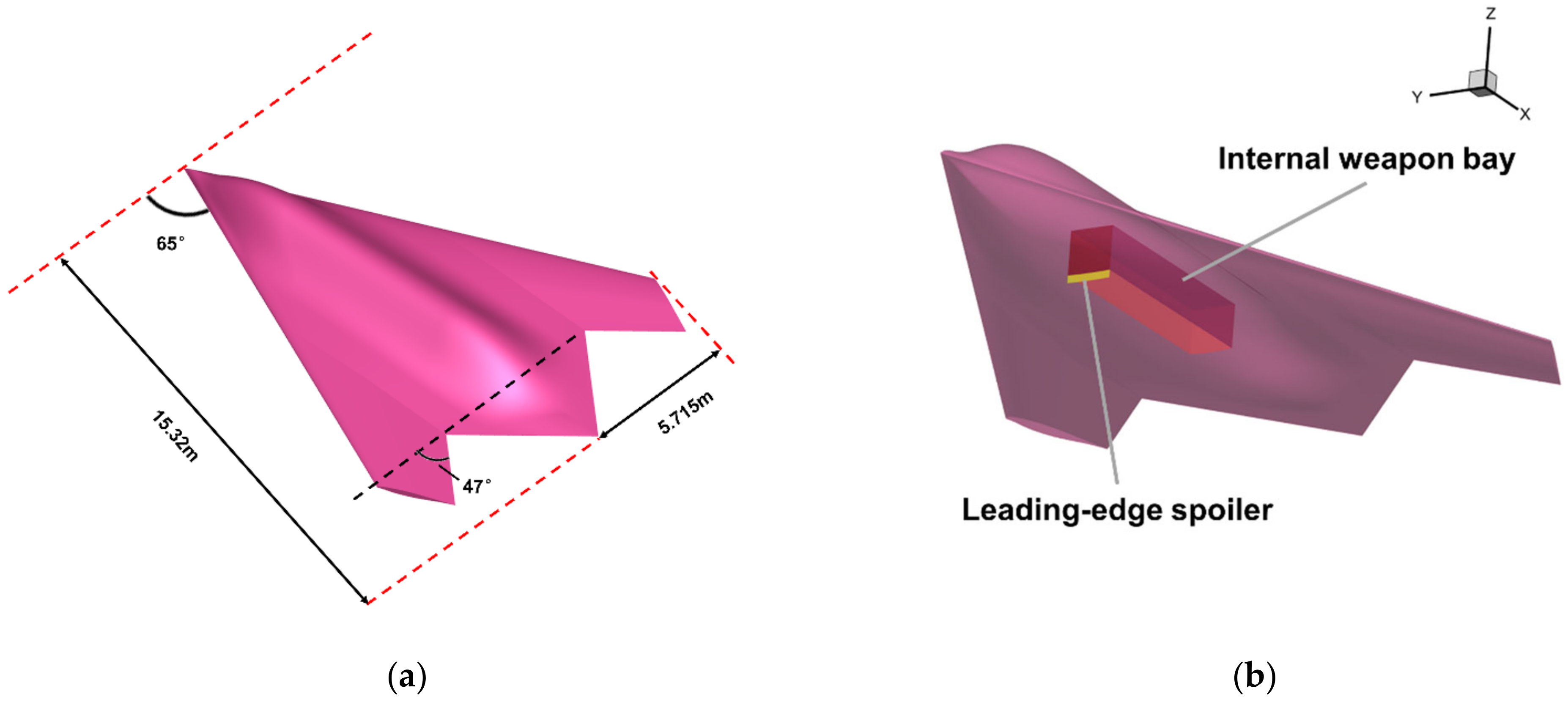
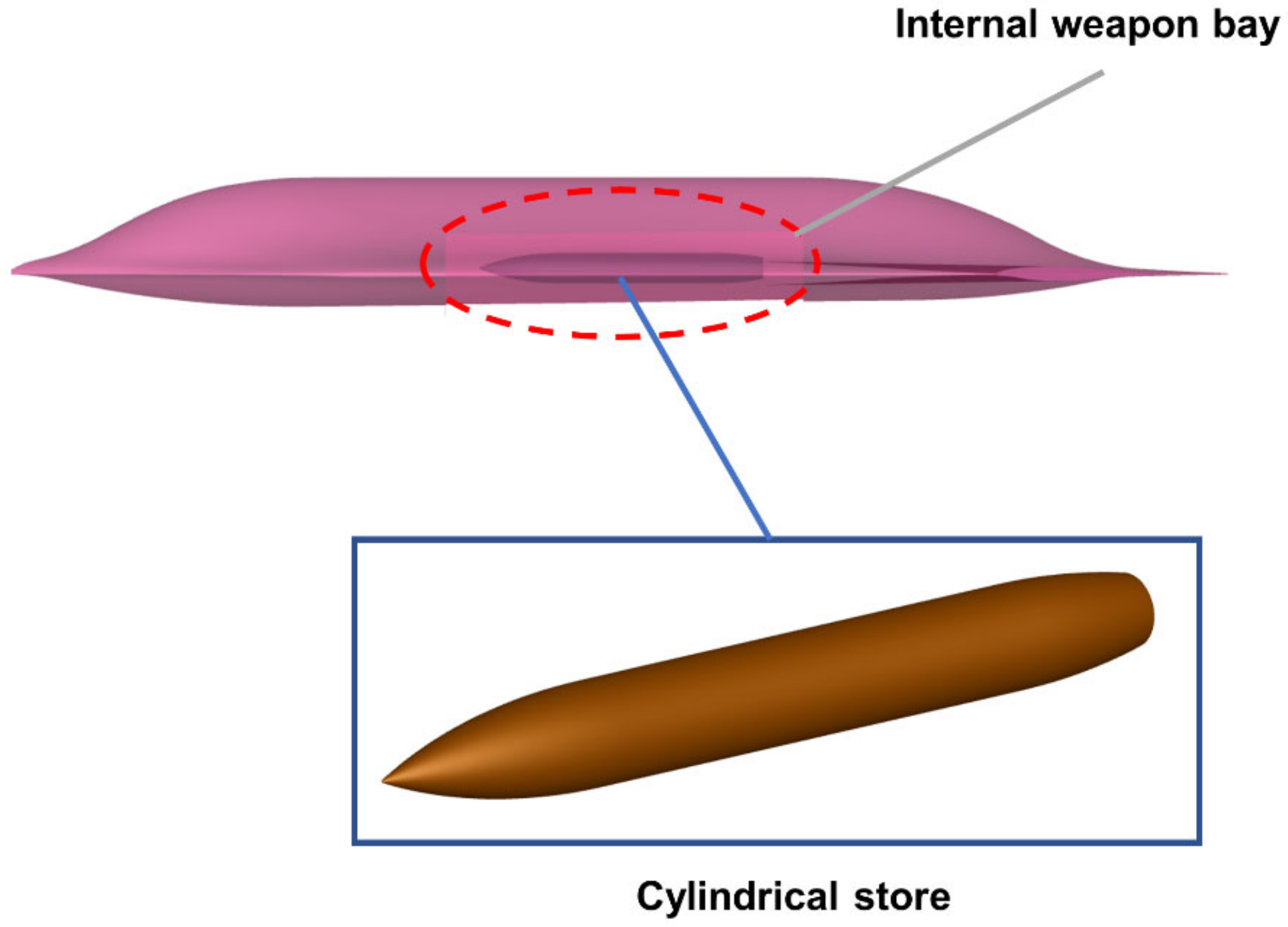
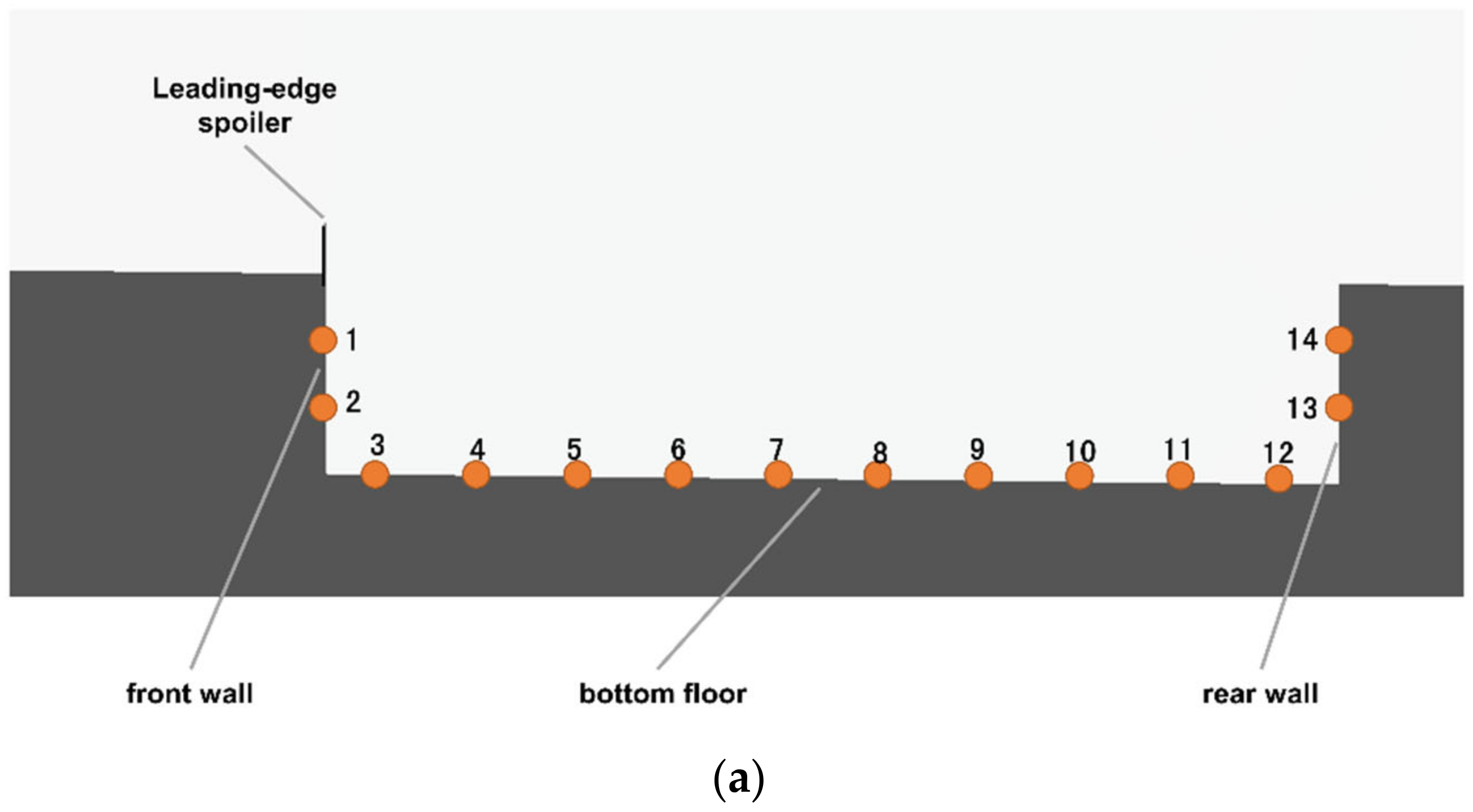
2. Model Description

The low-aspect-ratio configuration has the advantages of good stealth performance and high aerodynamic efficiency, which is an ideal choice for advanced aircraft. As shown in Figure 4, a low-aspect-ratio flying-wing model (LARFW) was designed to study the aerodynamic characteristics of low-aspect-ratio aircraft [24,25], of which the sweep angle of the leading edge is 65 degrees, the sweep angle of the trailing edge is 47 degrees, and the aspect ratio is 1.54. The other parameters of the LARFW are presented in references [26,27]. There is a large number of reliable experimental data and numerical data of the LARFW. As shown in Figure 4b, an internal weapon bay was set in the abdomen of the aircraft, and the details of the cavity are presented in Figure 5: The length is 4.43 m, the width is 0.88 m, the depth is 0.87 m, and the length-to-depth ratio is 5.09. Figure 6 shows a simplified cylindrical store loaded inside the internal weapon bay, which was designed to study the store-separation characteristics. The coordinates of this study were set as X pointing from the nose to tail, Y pointing to the right hand of the pilot, and Z being decided by the right-hand coordinate system.
The leading-edge flat spoilers of different height were set to study the flow control to the cavity, and the height of the spoilers is related to the thickness of the boundary layer at the leading edge of the cavity. Table 1 lists the freestream-flow conditions of the numerical simulation in this paper: the altitude is 10 km and the Mach number is 0.8, which is a typical flight condition for modern aircraft. The thickness of the boundary layer (δ) at the leading edge of the cavity is 0.08 m; therefore, the heights of the leading-edge flat spoilers were set as 0.06 m (0.75δ), 0.1 m (1.25δ), 0.2 m (2.5δ), and 0.3 m (3.75δ).
The comprehensive effects of the leading-edge flat spoiler to the flow characteristics, aerodynamic characteristics, and flow control of both store separation and aerodynamic noise are investigated in this paper. Only the LARFW model is used in the study of flow characteristics, aerodynamic characteristics, and aerodynamic noise. Both the LARFW model and the simplified cylindrical store are used in the study of store separation.

3. Numerical Method and Validation

First, the numerical method is presented in Section 3.1, including the FlowStar software, IDDES method, HLLE++ numerical scheme, and time-stepping method. When the cavity is exposed to high-speed free-stream flow, there would be a very complex flow field, which includes strong vortex/shear-layer/shock-wave interactions, and the IDDES method could provide the details of the complex flow field. The HLLE++ is a numerical scheme newly developed in recent years that has low numerical dissipation and could capture flow characteristics such as vortexes, shear layers, and shock waves well. Second, the mesh generation is described in Section 3.2. The grid-adaptation method is utilized to acquire more detailed flow structures, and the dynamic hybrid overset mesh method is utilized to simulate the store separation. Finally, the verification and validation are presented in Section 3.3, including IDDES method verification and store separation method verification.

3.1. Numerical Method

3.1.1. Software and Governing Equation

FlowStar software was used to simulate the cavity flows in this study, which is a self-developed flow solver of computational fluid dynamics (CFD) by China Aerodynamics Research and Development Center (CARDC) [28,29,30]. The software was developed based on the unstructured finite volume method and large-scale parallel-computing technology, and unsteady simulation and grid adaptation are the characteristics. The feature-based grid-adaptation method [31,32] and adjoint-based grid-adaptation method [33,34] were developed to provide accurate flow characteristics and aerodynamic characteristics.
The unsteady governing equation was utilized:
t Ω Q d V + Ω H ( Q ) n Q v g . n d S = Ω H v ( Q ) n d S
where Ω denotes the volume of the control volume, Q denotes the conservative state vector, v g denotes the wall velocity, n denotes the outward-pointing normal unit vector, H ( Q ) denotes the inviscid flux vector, and H v ( Q ) denotes the viscous flux vector. The conservative-state vector and flux vector can be described as:
Q = ρ ρ u ρ v ρ w ρ E T H ( Q ) = ρ V ρ u V + p n x ρ v V + p n y ρ w V + p n z ρ H V H v ( Q ) = 0 n x τ x x + n y τ x y + n z τ x z n x τ y x + n y τ y y + n z τ y z n x τ z x + n y τ z y + n z τ z z n x Θ x + n y Θ y + n z Θ z
where ρ is the density; u , v , and w are the velocities in three directions; E is the total energy; V is the contravariant velocity; p is the pressure; and τ is the viscous stress.
The inviscid flux was discretized with the HLLE++ scheme, which is introduced in detail in Section 3.1.3, and the viscous term was discretized by the central difference scheme. A Venkatakrishnan limiter was utilized to restrict numerical oscillation [35], which can be described as:
Ψ i = m i n j m i n ( 1 , ( d max ) 2 + ε 2 + 2 d f d max ( d max ) 2 + ε 2 + 2 ( d f ) 2 + d f d max ) d f > 0 m i n ( 1 , ( d m i n ) 2 + ε 2 + 2 d f d m i n ( d m i n ) 2 + ε 2 + 2 ( d f ) 2 + d f d m i n ) d f < 0      1              d f = 0
and the coefficients can be described as:
d f = q ( r f c j r c c ) d max = max ( max ( q j ) , q i ) q i d m i n = m i n ( m i n ( q j ) , q i ) q i
where q is the gradient, and q i and q j are the flow variables of left face and right face, respectively.

3.1.2. IDDES Method

The detached eddy-simulation (DES) method uses the Reynolds-averaged Navier–Stokes equations (RANS) to solve the thin boundary-layer area, and uses the large-eddy-simulation (LES) method to solve the other areas, which is essentially a hybrid method of the RANS and LES [36,37]. The DES method combines the advantages of RANS and LES, and could be used to simulate the unsteady separation flow. However, when the original DES method is used to solve the thick boundary layer, the flow would separate too early, which would result in an incorrect flow field. Therefore, the delayed detached-eddy-simulation (DDES) method and IDDES method were proposed to solve this problem [38,39]. In the IDDES method, the LES length scale for anisotropic grids near the wall is modified, which makes use of the wall distance along with the grid spacing. In addition, the blending of RANS and LES behavior within wall-modeled large-eddy simulation (WMLES) is modified, which greatly increases the resolved turbulence activity near the wall and finely adjusts the resolved logarithmic layer. The shear-stress-transport (SST) turbulence model was used in the prediction of IDDES method in this paper.
The length scale in the IDDES method is described as:
Δ = m i n { max [ 0.15 d w , 0.15 h max , l w ] , h max }
where h max = max ( Δ x , Δ y , Δ z ) , Δ x , Δ y , and Δ z are the grid scale in the three coordinate directions; l w denotes the length of the grid in the direction perpendicular to the wall; and d w denotes the distance to the nearest wall.
The IDDES method blends RANS and LES as:
l I D D E S = f d ( 1 + f e ) l R A N S + ( 1 f d ) l W M L E S
where l R A N S denotes the RANS length scale, l W M L E S denotes the WMLES length scale, f e is the correction coefficient, and other coefficients can be described as:
f d = 1 tanh [ C d r d ] 3 f d = max ( 1 f d ) , f B f B = m i n 2 exp ( 9 α 2 ) , 1.0 α = 0.25 d w h max r d = v t U i , j U i , j κ 2 d 2

3.1.3. HLLE++ Scheme

The numerical scheme is the foundation and soul of numerical simulation. There is a complex flow field of shear-layer/vortex/boundary-layer/shock-wave interaction in the high-speed cavity, which requires a low dissipative numerical scheme that could accurately capture the shear layers, vortexes, and shock waves. Some approximate Riemann schemes, such as the Roe scheme and HLLC scheme, are highly sensitive to how well the shock is aligned with the grid. When the grids are not aligned with the shock wave, cross-coupling between the Riemann problems in the different directions occurs, and the flow-field quality would be severely degraded, resulting in non-physical features, which are often called “carbuncles” [40]. The HLLE++ scheme uses a pressure-gradient-based switching function to locally transition to a more robust algorithm in the vicinity of strong shocks, and it removes error in the vicinity of non-grid-aligned shocks. The HLLE++ scheme produces almost-grid-independent solutions regardless of grid alignment with strong shocks.
The HLLE++ scheme is a newly developed method in recent years, and many CFD softwares, such as OVERFLOW [40], FlowStar [41,42], Kestrel, and KCFD [43,44], have developed this scheme. It has been shown that the HLLE++ scheme provide significantly better solutions than the original HLLC and Roe schemes for the flow fields with strong shocks, shear layers, and vortexes, and it is suitable for the numerical simulation of high-speed cavity flows.
The eigenvalue of HLLE++ scheme is defined as:
λ H L L E + + = β λ H L L E + + ( 1 β ) λ D
where λ H L L E + denotes the eigenvalue of HLLE+, λ D denotes the eigenvalue of the dissipative term, and β denotes the switching function, which can be defined as:
β = 1 tanh max k p , 75 75 100
where k p is a pressure-gradient-based switch sensor:
k p = 35 V c p p Ω 1 3
The switch is only activated where there are strong shocks and does not affect other areas of the flow, such as boundary layers. Therefore, The HLLE++ scheme could capture shocks without encountering the “carbuncle” phenomena, and it is also a low dissipative numerical scheme in the boundary layers.

3.1.4. Time Stepping

Dual time-stepping is utilized for time stepping, and the Lower Upper-Symmetric Gauss–Seidel (LU-SGS) is utilized to solve the governing equation [45]. The LU-SGS method divides the discrete governing equation into 3 parts:
( D + L ) D 1 ( D + U ) Δ W n = R I n
where D denotes a diagonal matrix, L denotes a strictly lower triangular matrix, and U denotes a strictly upper triangular matrix. Equation (11) can be solved with a forward sweep and a backward sweep:
( D + L ) Δ W ( 1 ) = R I n ( D + U ) Δ W n = D Δ W I ( 1 )
The LU-SGS method is widely used because it is relatively simple to execute and has low memory requirement. In order to acquire detailed unsteady-flow characteristics, the time step in unsteady simulation is 0.01 ms in this study.

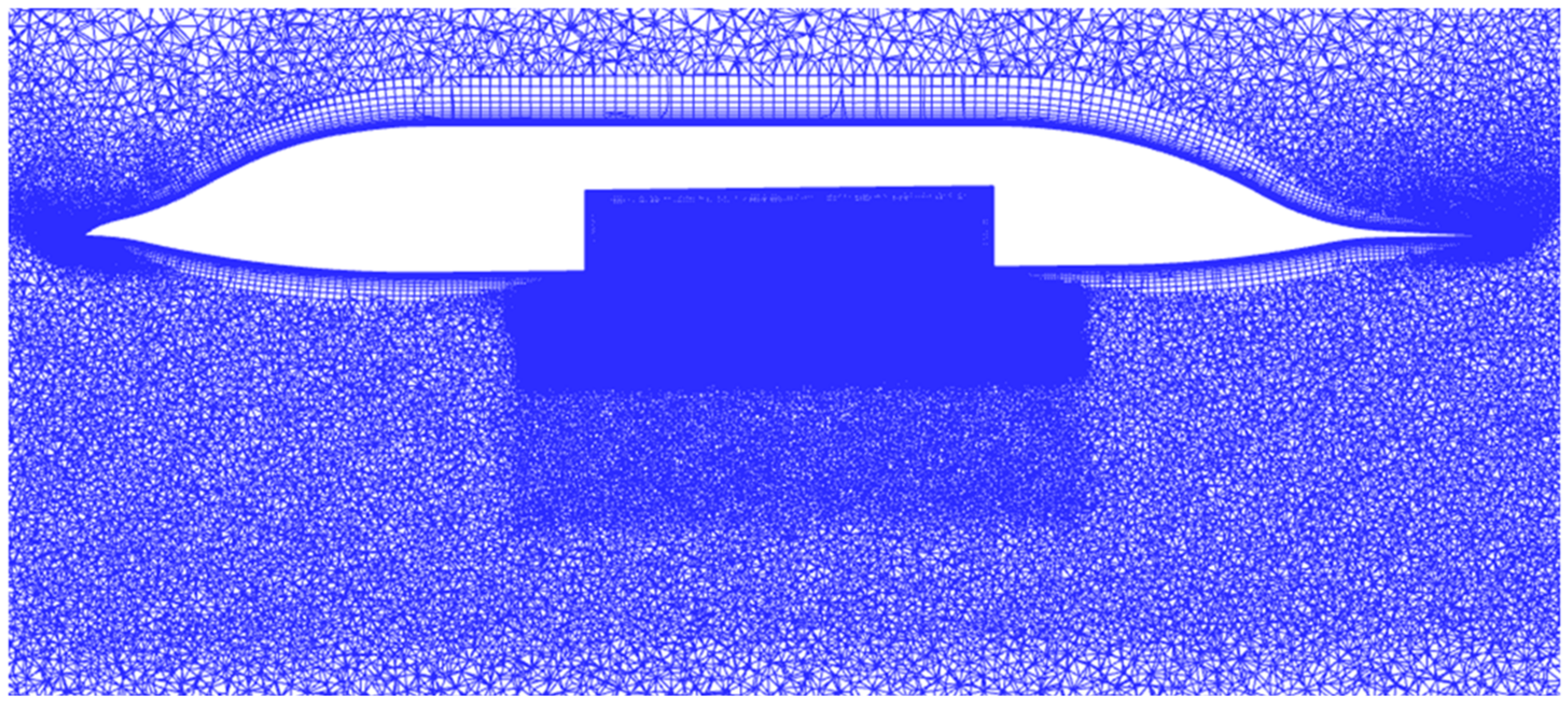
3.2. Mesh Generation

3.2.1. Generation of Basic Mesh

Reasonable design and high-quality generation of computational mesh are the prerequisites for the numerical simulation. In this paper, hybrid mesh was, hexahedrons, and triangular prisms were used in the boundary layer to better simulate the viscous flow; tetrahedrons were used for the simulation of the spatial-flow field; and pyramid elements were utilized for the transition between hexahedrons, prisms, and tetrahedrons. Figure 7 and Figure 8 present the basic mesh of the LARFW, in which the grid areas near the cavity were specially locally refined to capture the detailed flow characteristics, such as shear layers, vortexes, and boundary layers. The grid scale of the first layer is 0.000002 m according to the criterion of y+ < 1, and the number of the grid elements of the LARFW is about 41 million. As for the boundary conditions, all the surfaces of the LARFW and the internal weapon bay are wall boundaries, and there is a large far-field boundary on the outside.

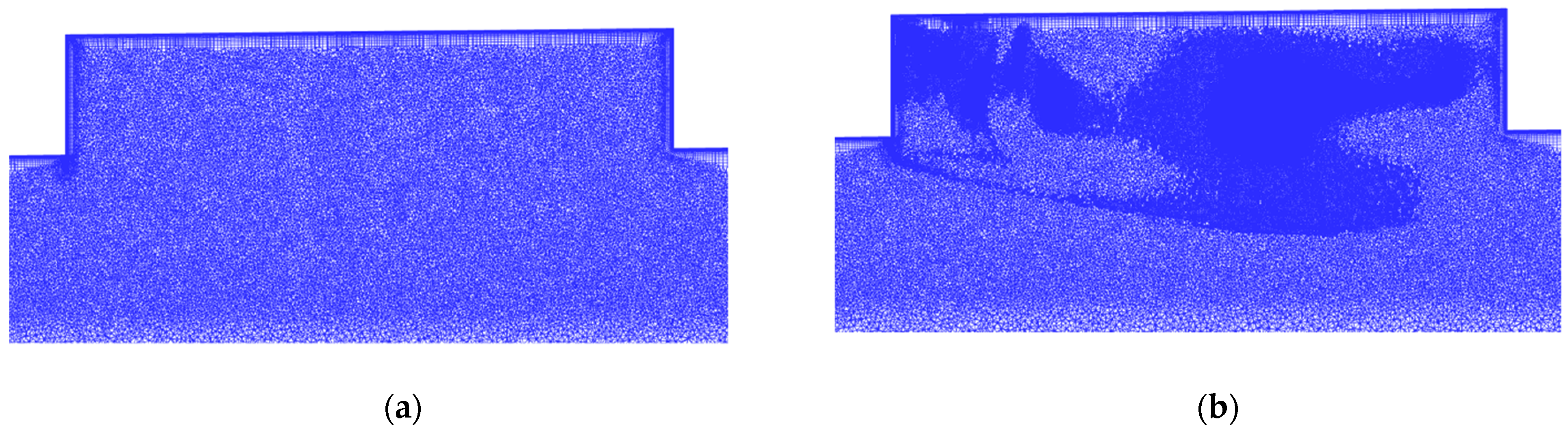
3.2.2. Grid-Adaptation Method

Grid adaptation is a popular method to improve the resolution of the flow field and the accuracy of numerical simulation, which automatically optimizes the grid distribution instead of complicated manual work [46,47]. The grid-adaptation method can be roughly categorized as feature-based and adjoint-based grid adaptation. The former is used to capture flow features such as vortexes, shock waves, and shear layers, and the latter is used to provide more accurate aerodynamic characteristics such as the lift force and drag force. There is a complex flow field of strong shear layers and vortexes in the cavity; therefore, the feature-based adaptation was utilized to study the basic flow characteristics in this study. Figure 9 presents the grid adaptation of the cavity of the LARFW with a leading-edge flat spoiler, and it can be seen that the cells in areas of shear layers and vortexes were automatically optimized, which would provide a high-resolution flow field.

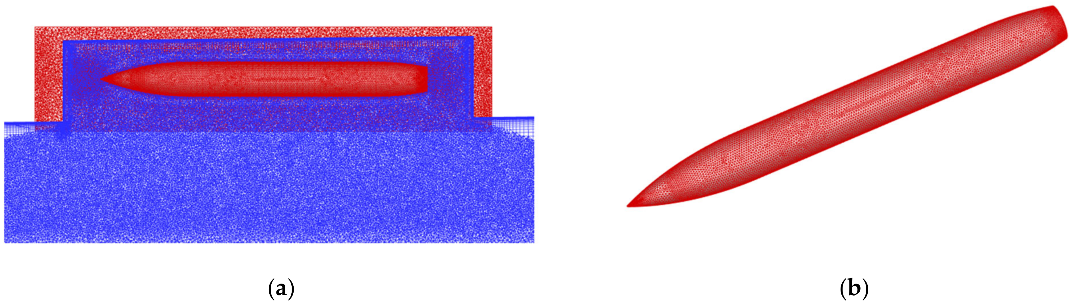
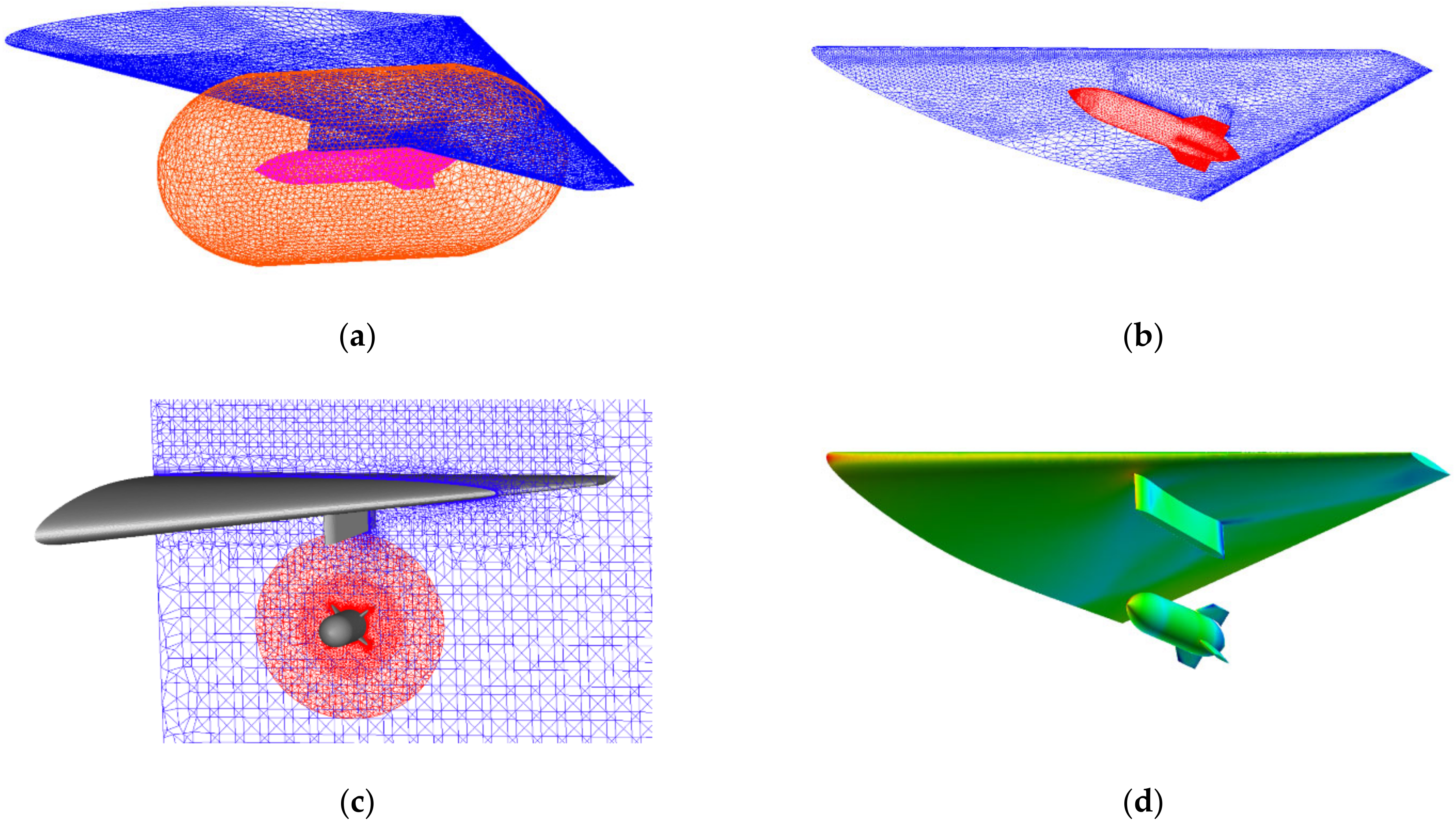
3.2.3. Conservative Overset Mesh Method

The dynamic hybrid overset mesh method is the most widely used method for simulating multi-body separation, and it was utilized to simulate the store separation in this study. The overset mesh method divides the complex flow area into many independent sub-areas, and the mesh of each area is generated independently. The flow field of each area is also simulated independently, and the date of each mesh is transferred in the overlapping areas.
The overset mesh needs to exclude the elements that do not participate in the calculation, which is also called “hole cutting”. A “direct cutting” strategy is used in FlowStar, which uses the solid-surface-intersection criterion to determine the hole boundary [28,48,49]. The “direct cutting” strategy does not require auxiliary mesh and could provide high efficiency and robustness. The data transfer between overlapping grids is the basis for ensuring the correct calculation, especially for a high-speed flow field with strong shocks and vortexes. A conservative data-transfer method [50], based on the supermesh technology and the center-based finite-volume method, is used in FlowStar, which could ensure the accuracy of overset mesh method.
Figure 10 presents the overset mesh of store separation, which contains two sub-meshes: the mesh of the LARFW and the mesh of the simplified cylindrical store, and the number of grid elements of the store is about 4 million. The grid scale of the store matched well with the grid scale of the LARFW, which could ensure the accuracy of the overset mesh.

3.3. Verifications and Validations

3.3.1. IDDES Method Verification

The M219 cavity is a benchmark widely used in the numerical verification of DES-type methods, and there is a large number of reliable experimental data and numerical data of the M219 cavity [51,52]. The M219 cavity was used to verify the IDDES method in this study. The details of the configuration of the M219 cavity are presented in Refs. [53,54]. There are 10 monitoring points at the bottom of the cavity to monitor the pressure fluctuation (Figure 11). The grid scale of the first layer is 0.000002 m according to the criterion of y+ < 1, the time step in unsteady simulation is 0.01 ms, and the freestream flow conditions of numerical simulation are the same as wind-tunnel experiments [55]. The sound-pressure level was computed as:
S P L = 20 lg p r m s p r e f
where p r e f = 2 × 10 5   P a is the minimum audible pressure variation, and p r m s is the root-mean-square pressure along the cavity.
The numerical results of this study were compared with the results of wind-tunnel experiments. The overall sound-pressure level (OASPL) at the bottom floor is presented in Figure 12, and sound-pressure levels of each monitoring point are presented in Figure 13. It can be seen that the CFD results are in good agreement with the wind-tunnel experiments.

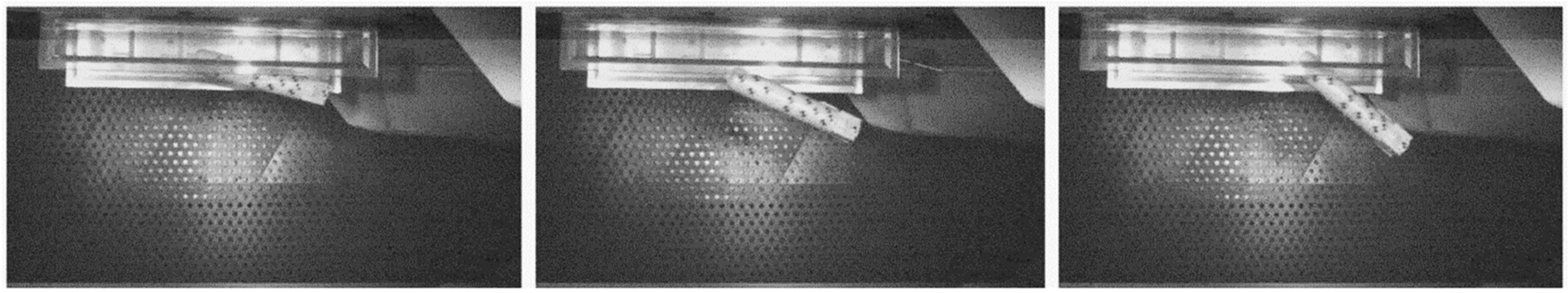
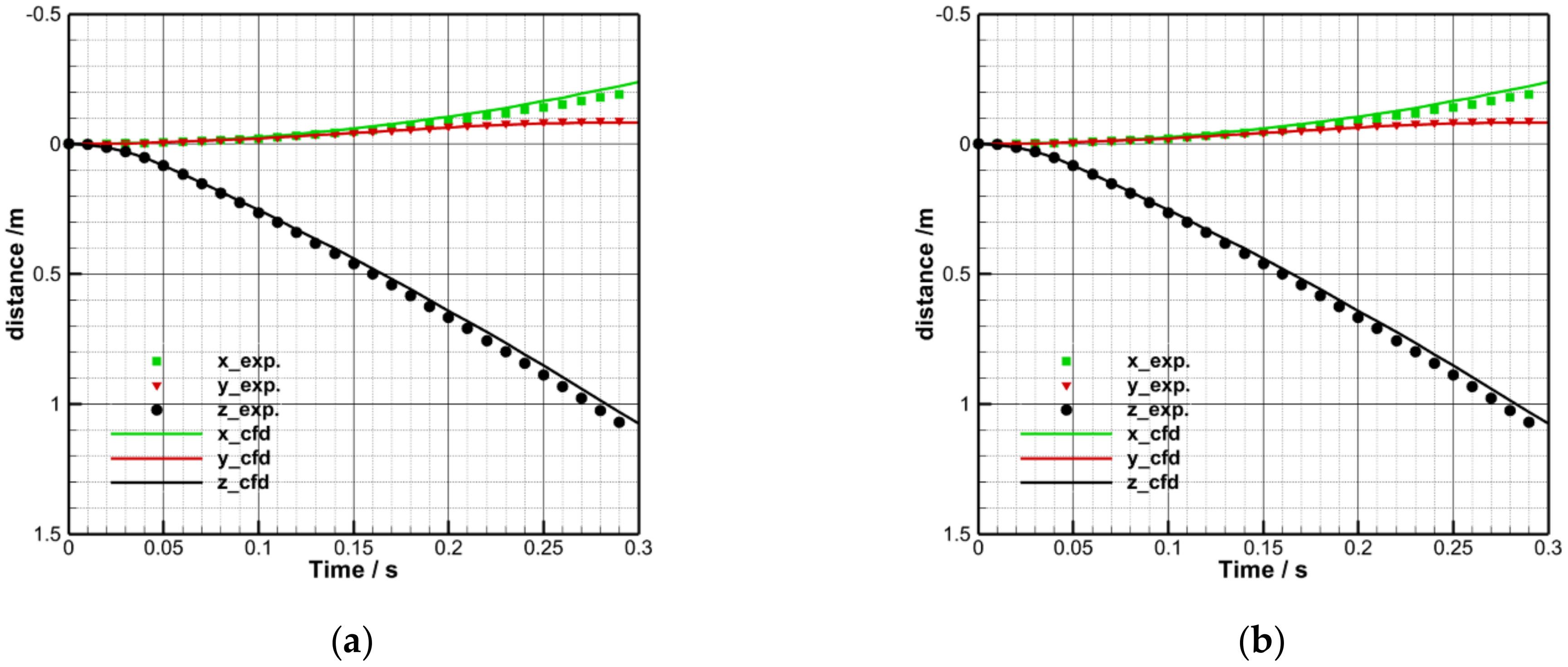
3.3.2. Validation of Store Separation

Wing/Pylon/Finned Store (WPFS) is a benchmark designed by Arnold Engineering Development Center (AEDC) that is widely used in the numerical-method verification of multi-body separation [56]. The WPFS was used to verify the numerical method of store separation in this study. Figure 14 presents the overset mesh of WPFS, including two sub-meshes, one being the mesh of the wing and pylon, and the other the mesh of the finned store. The comparison of the store-separation characteristics between CFD and the experiments is presented in Figure 15. It can be seen that the CFD results are in good agreement with the wind-tunnel experiments, which indicates that the numerical method of store separation in this study is suitable for the store separation from the LARFW.
In summary, the numerical method was fully validated, including IDDES-method verification and wind-tunnel-experiment validation of WPFS, which indicates that the numerical method in this study is suitable for the research of flow characteristics, aerodynamic noise, and store separation of the internal weapon bay.

4. Results and Discussion

Figure 16 shows the contours of the pressure coefficient and Mach number for the “clean” cavity without the leading-edge flat spoiler, and Figure 17, Figure 18, Figure 19 and Figure 20 show the contours of the pressure coefficient and Mach number for the cavities with the leading-edge flat spoilers of different heights. In addition, the Q-criterion is a common method used to identify and visualize the structure of the spatial vortex. Figure 21 shows the spatial streamlines and iso-surface of the Q-criterion for the “clean” cavity, and Figure 22, Figure 23, Figure 24 and Figure 25 show the spatial streamlines and iso-surface of the Q-criterion for the cavities with the leading-edge flat spoilers of different heights. It can be seen that the numerical simulation successfully captured the detailed flow structures, including the shear layers and vortexes. In addition, the leading-edge flat spoiler before the cavity completely changed the pressure distribution, shear layers, and vortexes of the cavity, and the height of the spoiler had a significant effect on the flow characteristics. The comprehensive effects of the leading-edge flat spoiler on the flow characteristics, aerodynamic characteristics, and the flow control of both store separation and aero-dynamic noise are discussed in detail in the following sections.

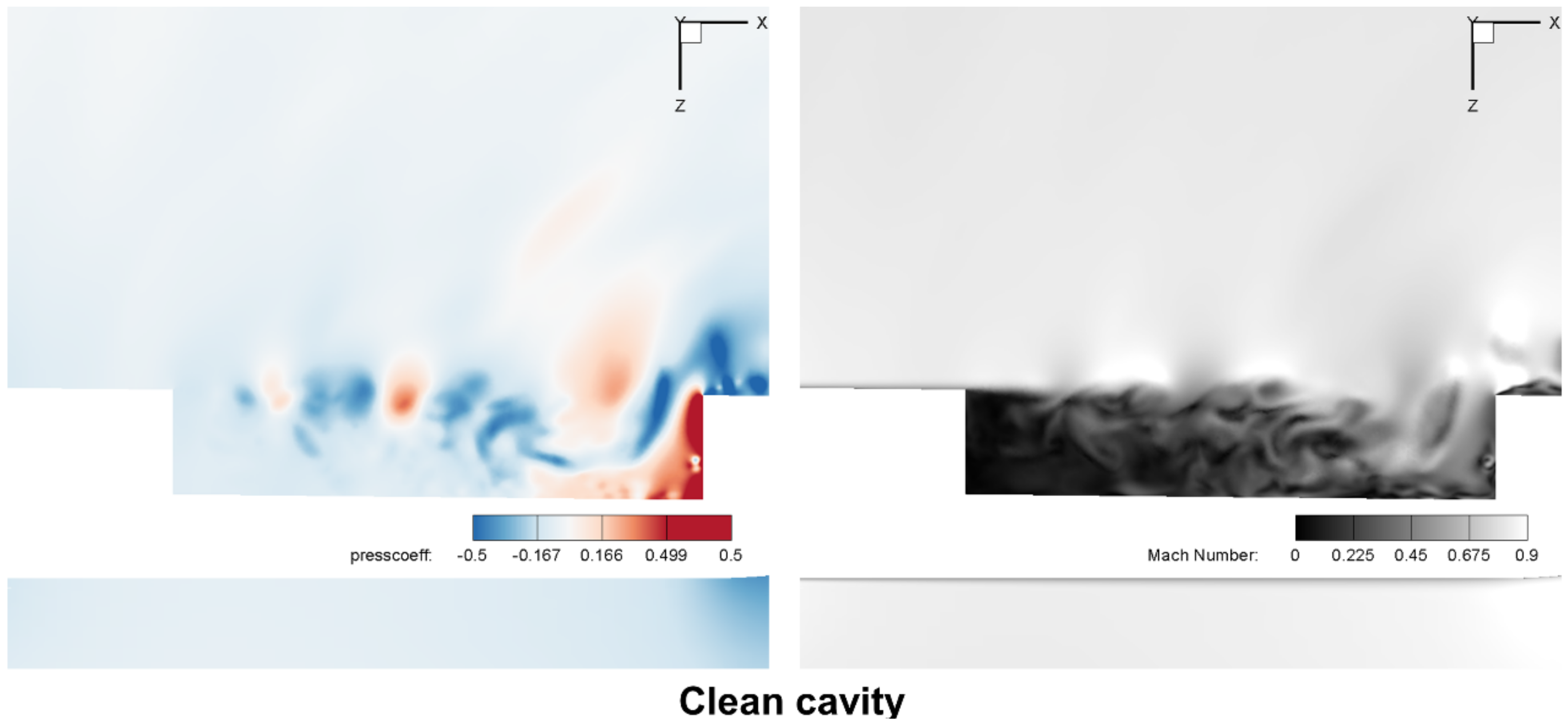
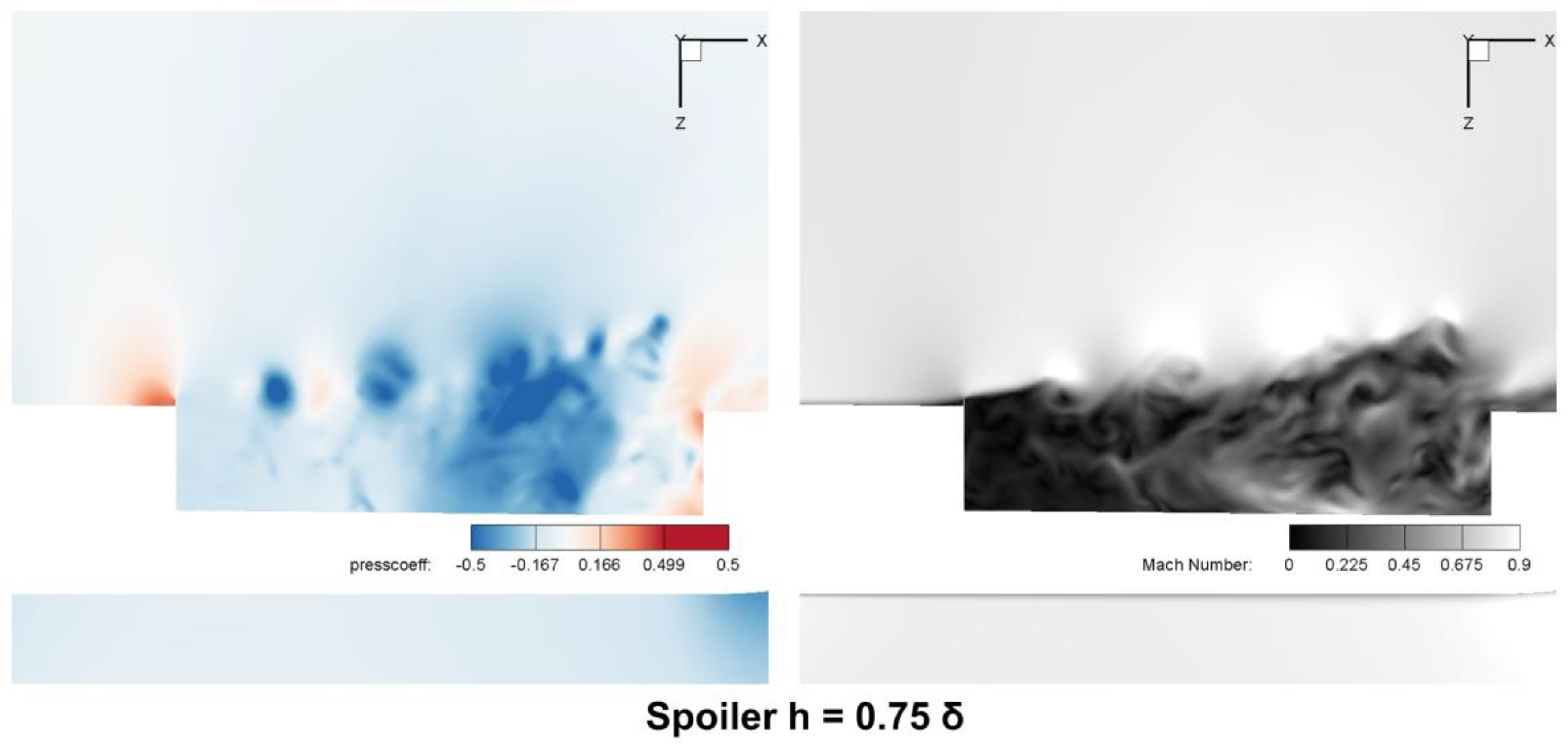
4.1. The Effects of the Leading-Edge Flat Spoiler to Flow Characteristics
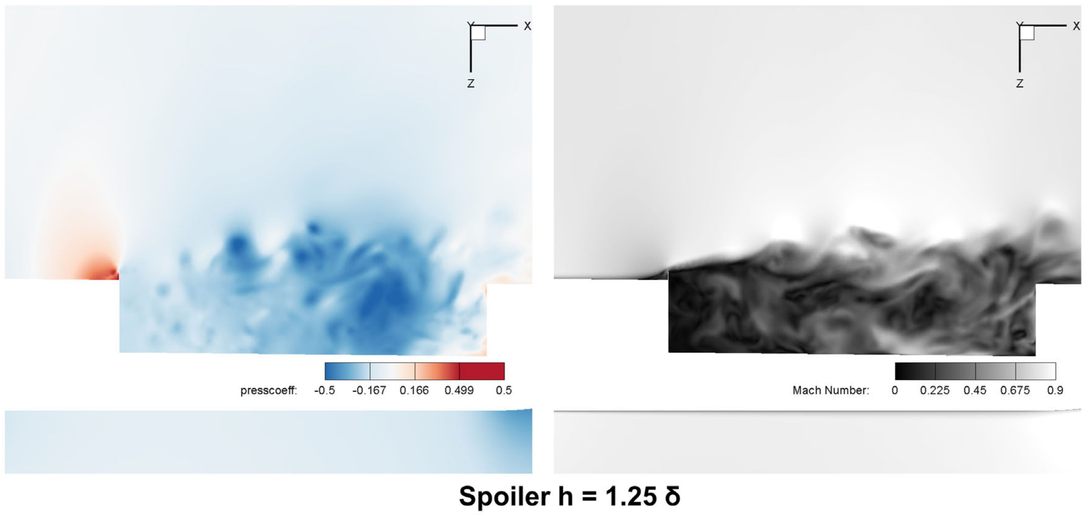
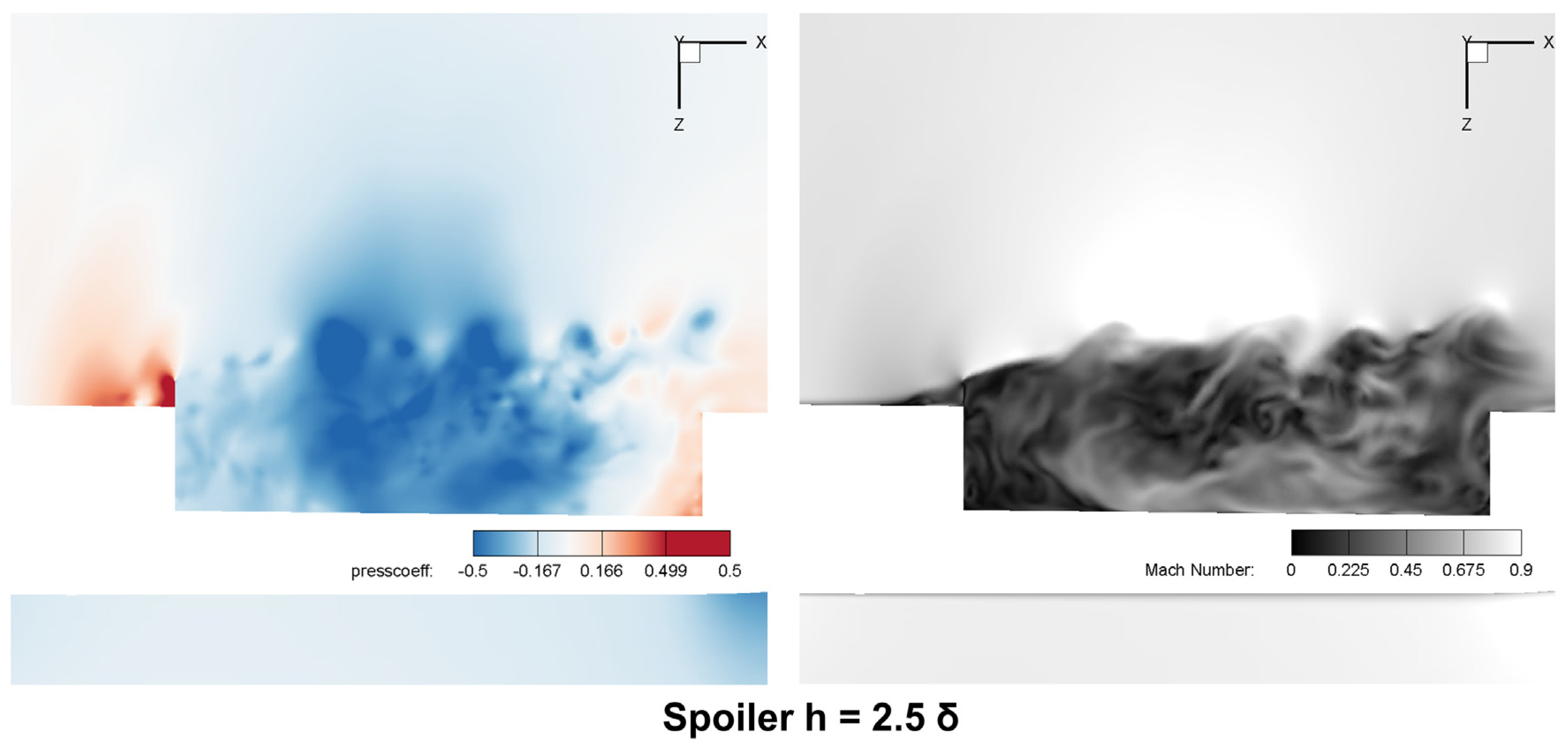
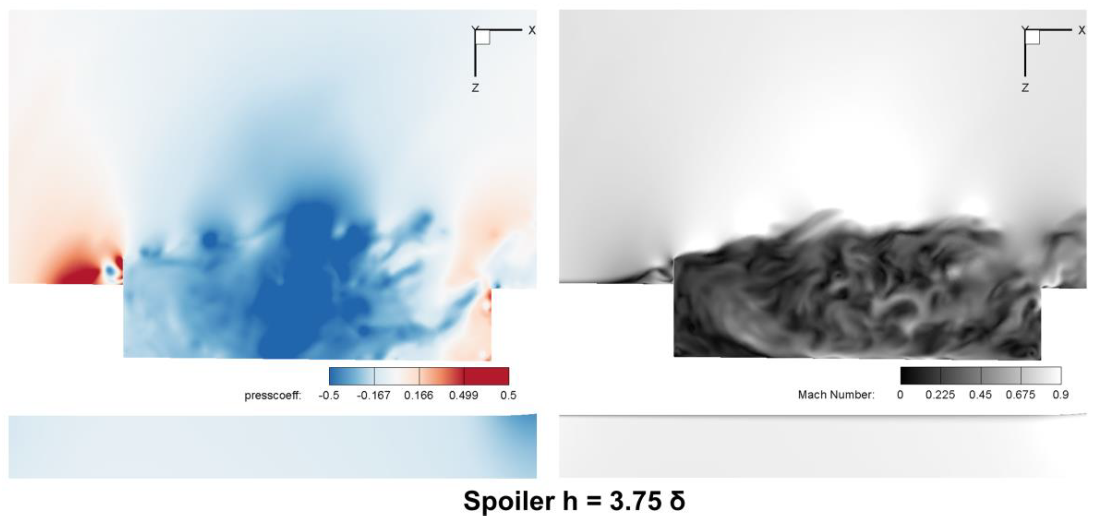
4.1.1. Shear Layers

Previous studies on the simple regular rectangular cavity without the aircraft have shown that the leading-edge spoilers can lift up the incoming shear layer, and a similar conclusion can be drawn for the cavities of low-aspect-ratio flying-wing aircraft. Figure 26 shows the basic schematic diagrams of the cavity flow in this study. As shown in Figure 16, Figure 21 and Figure 26a, for the clean cavity, the shear layer started from the leading edge of cavity, and it was basically a two-dimensional flow at the beginning. Then, there were gradually unsteady disturbances of the shear layer, and the shear layer gradually became a three-dimensional flow. The shear layer passed through the cavity and directly impacted on the rear wall of the cavity. It can be seen from Figure 17, Figure 18, Figure 19, Figure 20, Figure 22, Figure 23, Figure 24 and Figure 25 that for the cavities with the leading-edge flat spoiler, the shear layer was lifted up before the leading-edge spoiler. In addition, the leading-edge spoiler brought in unsteady disturbances to the shear layer and made it a three-dimensional flow after the spoiler. Furthermore, the leading-edge spoiler pushed the high-speed flow outside the cavity, in our cases, and all the shear layers directly bypassed the cavity and arrived at the surface after the cavity (Figure 26b), instead of directly impacting on the rear wall of the cavity. The height of the leading-edge spoiler also affected the shear layer, with the higher spoiler producing a higher shear layer.

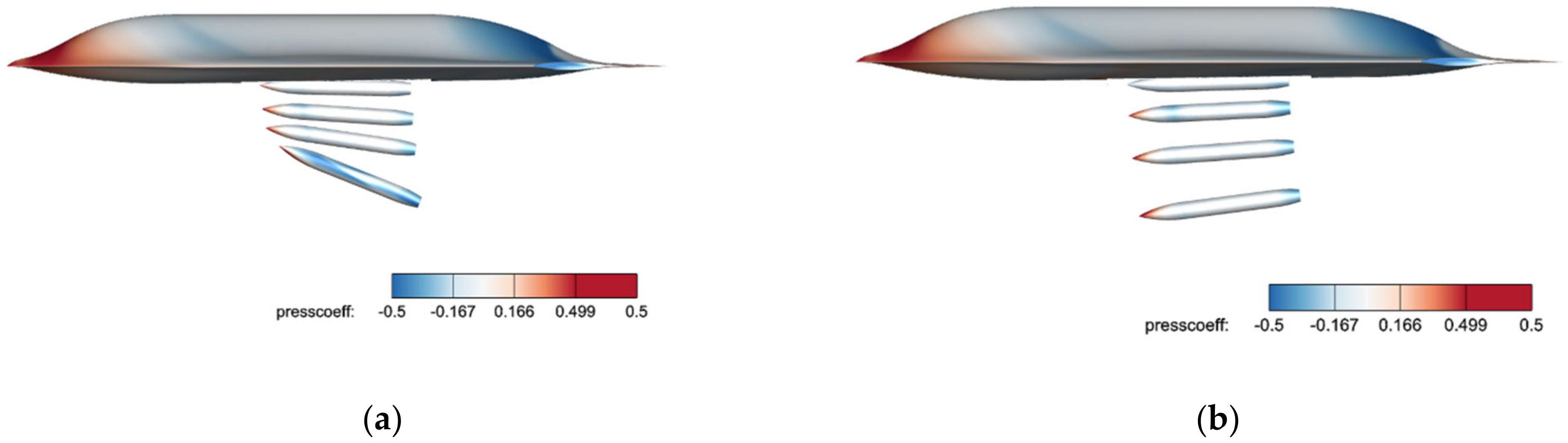
4.1.2. Pressure Distribution

First, the leading-edge flat spoiler greatly changed the pressure distribution inside the cavity. As shown in Figure 16, for the clean cavity, the shear layer passed through the cavity and directly impacted on the rear wall of the cavity, and the flow of high dynamic pressure produced local high pressure on the rear wall. In addition, plenty of high-speed flow entered the cavity, resulting in high pressure inside the cavity. It can be seen from Figure 17, Figure 18, Figure 19 and Figure 20 that for the cavities with the leading-edge flat spoiler, the shear layer was lifted up, directly bypassed the cavity, and arrived at the surface after the cavity, instead of directly impacting on the rear wall; therefore, the pressure at the rear wall and bottom floor of the cavity was significantly reduced. In addition, the leading-edge spoiler pushed most of high-speed flow outside the cavity, which resulted in a lower pressure distribution inside the cavity.
Second, the leading-edge flat spoiler also had an enormous influence on the pressure distribution outside the cavity. As shown in Figure 17, Figure 18, Figure 19, Figure 20 and Figure 26b, the leading-edge spoiler blocked the coming flow around the aircraft, and the high-speed flow impacted on the leading-edge spoiler and produced high pressure both on the spoiler and the surface of aircraft, which would create additional drag on the aircraft.
Furthermore, the height of the leading-edge spoiler also affected the pressure distribution. On the one hand, with the increasing height of the spoiler, the overall pressure inside the cavity became lower and lower. As shown in Figure 22, Figure 23, Figure 24 and Figure 25, the flow mechanism was that the higher spoiler pushed most of high-speed flow outside the cavity, leading to lower pressure inside the cavity. On the one hand, as shown in Figure 17, Figure 18, Figure 19 and Figure 20, with the increasing height of the spoiler, the blocking effect of the spoiler also increased, which resulted in a higher pressure both on the spoiler and the surface of aircraft.

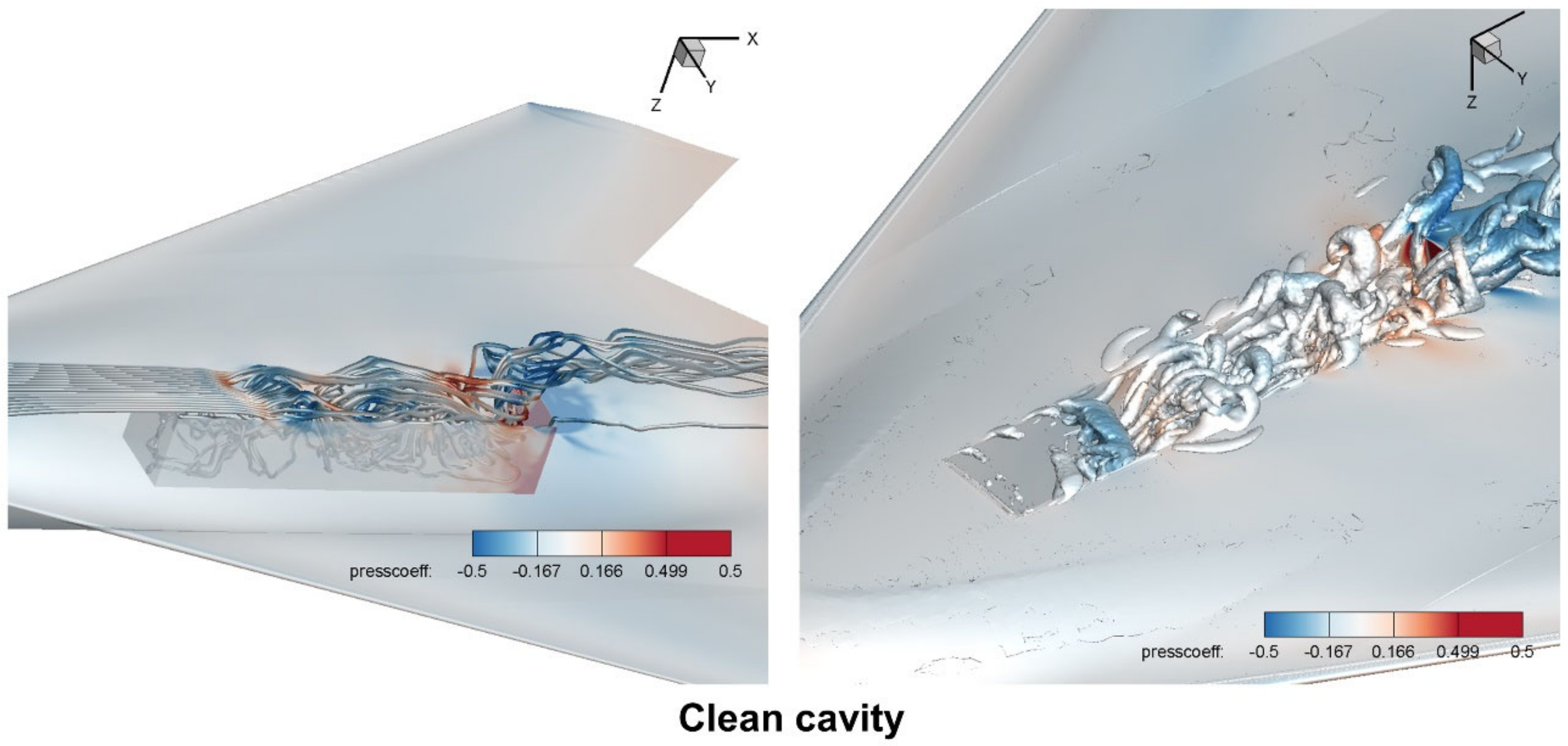
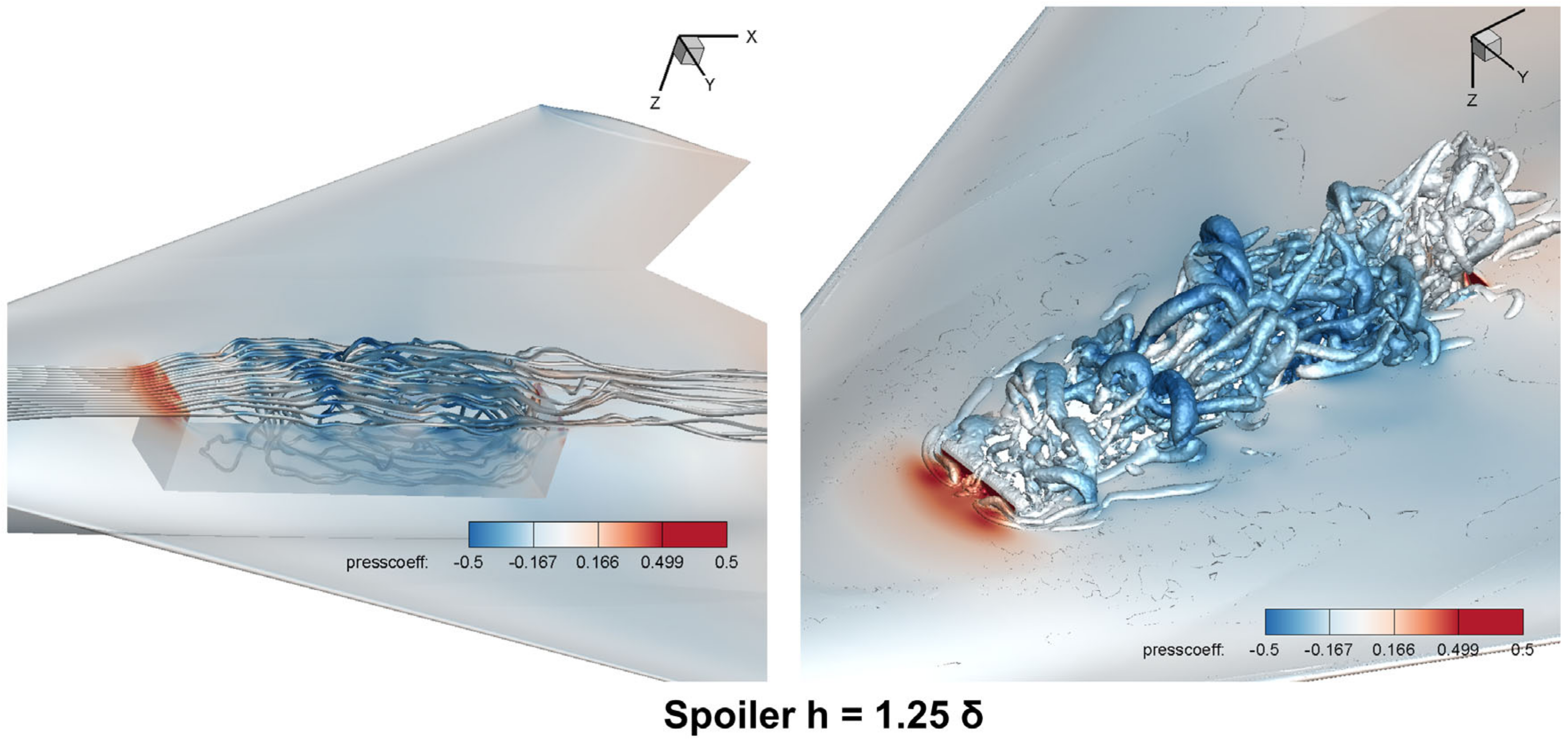
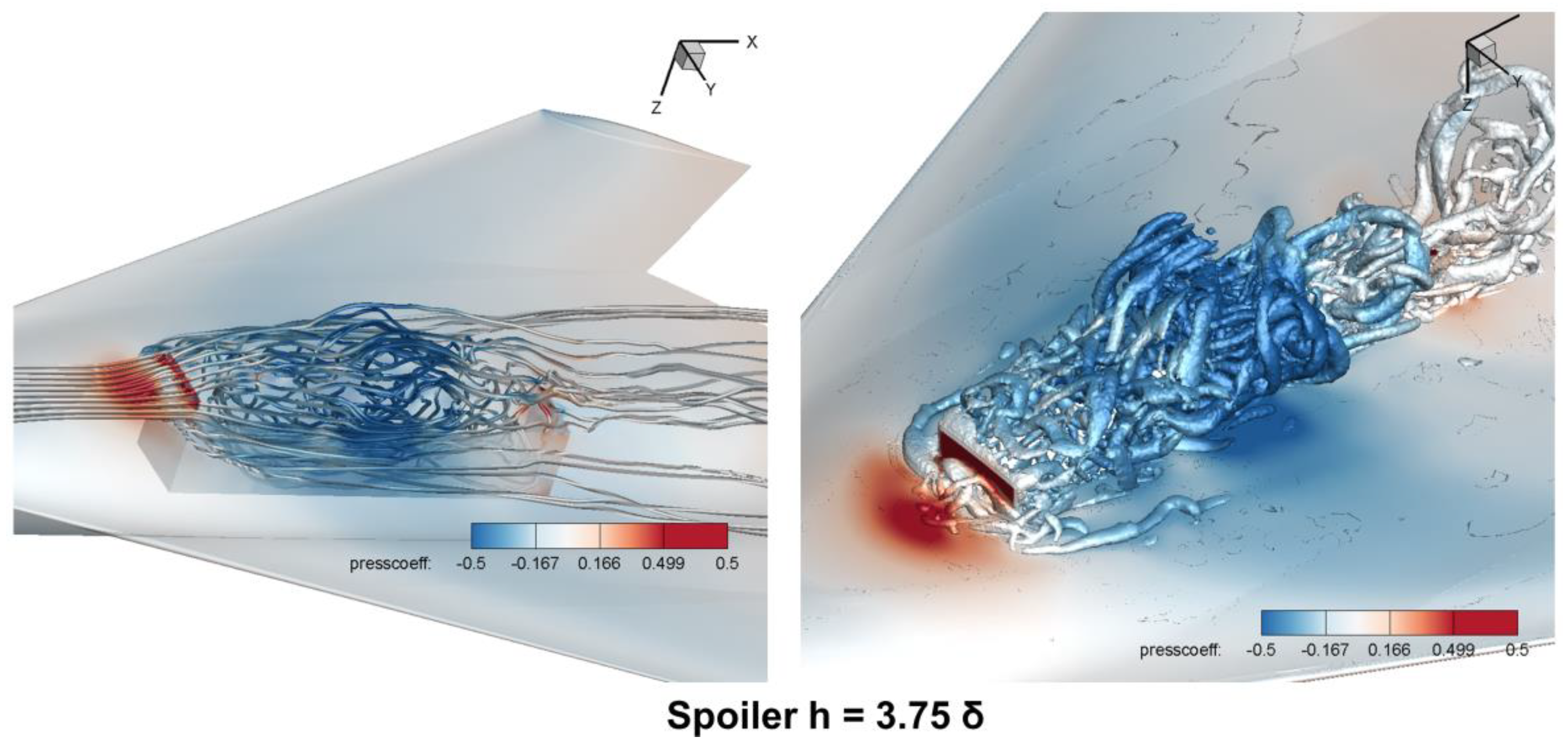
4.1.3. Large-Scale Vortexes

The vortex is one of the main flow characteristics of cavity flows. In our case, as shown in Figure 21, Figure 22, Figure 23, Figure 24, Figure 25 and Figure 26, there were always large-scale vortexes inside the cavity with or without the leading-edge spoiler. It can be seen that the large-scale vortex in the clean cavity was located near the rear of the cavity; however, the large-scale vortex in the cavities with a leading-edge spoiler were located in the middle of the cavity. In addition, with the increasing height of the spoiler, the vortex in the middle of the cavity became larger and larger, and it moved upstream closer to the front of the cavity. Furthermore, due to the blocking effect of the leading-edge spoiler, some small-scale vortexes were generated before the spoiler, which did not exist in the clean cavity.
There were large-scale vortexes inside the cavities both with and without the leading-edge spoiler; however, the generation mechanisms of the vortexes were completely different. As shown in Figure 26a, for the clean cavity, the flow of high dynamic pressure directly impacted on the rear wall of the cavity, and a large recirculating vortex was generated due to the blocking effect of the rear wall. Furthermore, the high pressure at the rear wall produced a large adverse pressure gradient, which further promoted the generation of the large-scale vortex.
Figure 26b shows the generation mechanisms of vortexes for the cavities with the leading-edge flat spoiler. As discussed in Section 4.1.2, the leading-edge spoiler pushed most of high-speed flow outside the cavity, which resulted in a lower pressure distribution inside the cavity. Therefore, there was a strong adverse pressure gradient outside and inside the shear layer, which drove the flow to separate into the cavity and generated a large-scale vortex. In addition, the height of the leading-edge spoiler also affected the large-scale vortex. With the increasing height of the spoiler, the overall pressure inside the cavity became lower and lower, and the adverse pressure gradient outside and inside the shear layer became stronger and stronger; therefore, the vortex insides the cavity became larger and larger. In addition, the stronger adverse pressure gradient made the flow separate into the cavity earlier, so with the increasing height of the spoiler, the vortex moved upstream closer to the front of the cavity.

4.2. The Effects of the Leading-Edge Flat Spoiler on Store Separation

The store-separation characteristics for the internal cavities of the LARFW are presented in Figure 27. Figure 27a shows the store separation from the clean cavity, and Figure 27b shows the store separation from the cavity with leading-edge flat spoiler (the height of the spoiler is 0.2 m (2.5δ)). It can be seen that the store was in a large nose-up attitude when separating from the clean cavity, which is a dangerous store separation and would cause two risks. First, the nose-up attitude of the store also produces large lift force, and as a result, in some cases the store would collide with the aircraft (Figure 2). Second, the controllability of the control system of the store is limited, and in some cases the store would be out of control due to excessive nose-up attitude. Therefore, = pilots usually want the store to be in a nose-down or horizontal attitude, which would not be a threat to the aircraft. As shown in Figure 27b, for the cavity with the leading-edge flat spoiler (the height of the spoiler is 0.2 m), the store was in a slight nose-down attitude when separating from the cavity, which is better for the safety of the aircraft. The leading-edge spoiler changed the pitching trend of the store and greatly improved the safety of the store separation.
As discussed with the pressure distribution in Section 4.1.2, for the clean cavity, the shear layer passed through the cavity and directly impacted on the rear wall; the flow of high dynamic pressure produced a local high pressure on the rear wall and bottom floor, whereas the pressure near the front wall was lower. The pressure distribution made the store produce a nose-up pitching moment. The store was in a nose-up attitude during separation from the cavity, which also produced large lift force, and as a result, the store separated slowly from the clean cavity. For the cavity with the leading-edge flat spoiler, the shear layer was lifted up and directly bypassed the cavity, the pressure at the rear wall and bottom floor of the cavity was significantly reduced, and the spoiler reduced the pressure near the leading edge and there was a lower pressure at the lower surface at the head of the store. As a result, the store produced a nose-down pitching moment and was in a nose-down attitude during separation.
The height of the leading-edge spoiler also affected the store separation. Figure 28 shows the pitching attitude during separation under leading-edge spoiler flow control with different heights. In our case, all the spoilers reduced the nose-up trend of the store and improved the safety of store separation. In addition, with the increasing height of the spoiler, the store produced a more obvious nose-down attitude during separation, which is good for the safety of the aircraft.
The results of this study show that the leading-edge flat spoiler is an excellent passive flow-control method for store separation that completely changes the store-releasing characteristics. The spoiler curbs the nose-up trend of the store and produces a safe and stable store separation.

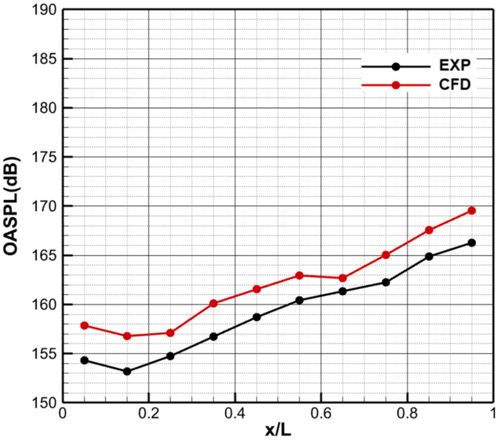
4.3. The Effects of the Leading-Edge Flat Spoiler on Aerodynamic Noise

The highly unsteady flow could produce high aerodynamic noise inside the cavity. Fourteen monitoring points were set on the wall of cavity to investigate the pressure fluctuations (Figure 29a). The overall sound-pressure level (OASPL) of the clean cavity and cavities with different spoilers is presented in Figure 29b, and it can be seen that for the clean cavity, the front part of the cavity was relatively quiet and the sound-pressure level (SPL) was amplified downstream. The highest SPL occurred on the rear wall of the cavity, especially near the tailing edge. On the other hand, for the cavities with leading-edge flat spoilers, the rear part of the cavity was relatively quiet and the highest SPL occurred in the middle of the cavity. In our case, compared with the clean cavity, the leading-edge flat spoiler reduced the SPL at the rear cavity (max 8.2 dB) but increased the noise at the middle and front part of the cavity (max 11.3 dB). The height of the leading-edge spoiler also affected the aerodynamic noise. As shown in Figure 29b, the higher spoiler produced lower noise on the rear wall but higher noise at the middle and front part of the cavity.
Figure 30 shows the instantaneous flow fields of the clean cavity and the cavity with the leading-edge flat spoiler. The aerodynamic noise inside a cavity is mainly caused by the impacts of unsteady flows. For the clean cavity, as shown in Figure 30a, the shear layer directly impacted on the rear wall of cavity, resulting in large unsteady disturbances and large aerodynamic noise. In addition, as discussed in Section 4.1.3, the large-scale vortex in the clean cavity was located at the rear part of the cavity, and the oscillation of the unsteady vortex caused large disturbances to the rear wall and bottom floor, which resulted in a large aerodynamic noise.
For the cavity with the leading-edge flat spoiler, the shear layer was lifted up, directly bypassed the cavity, and arrived at the surface after the cavity, instead of directly impacting on the rear wall, therefore, the unsteady disturbances at the rear part of the cavity were reduced compared with the clean cavity, which resulted in lower aerodynamic noise. The aerodynamic noise at the middle of cavity was mainly caused by the unsteady oscillation of the large-scale vortex. As discussed in Section 4.1.3, the leading-edge spoiler pushed part of the high-speed flow outside the cavity and caused a strong adverse pressure gradient outside and inside the shear layer, which drove the flow to separate into the cavity and generated a large-scale vortex in the middle of the cavity. As shown in Figure 30 and Figure 21, Figure 22, Figure 23, Figure 24, Figure 25 and Figure 26, the large-scale vortex in the middle of the cavity caused large unsteady oscillation, which resulted in a large aerodynamic noise. In addition, with the increasing height of the spoiler, the vortex inside the cavity became larger and larger, and the vortex moved upstream closer to the front of cavity; therefore, the SPL in the middle of the cavity became larger and larger, and the location of highest SPL also moved upstream closer to the front of the cavity.
The results in this study show that for the internal cavity of the LARFW aircraft, the leading-edge spoiler reduced the noise in the rear of the cavity (max 8.2 dB) but increased the noise in the middle of the cavity (max 11.3 dB). The results of this study are similar to the results of Zhang and Schmit [20,21]. Not all leading-edge spoilers can reduce the aerodynamic noise inside the cavity, which depends on the configuration of cavity/aircraft, the flow conditions, and the configuration of the leading-edge spoilers. For example, Zhang studied the flow control of leading-edge modifications with a cavity based on both wind-tunnel experiments and numerical simulation, and the cavity was located in the abdomen of a real aircraft. The results showed that some typical passive flow-control methods, such as leading-edge sawtooth, leading-edge column, and flat spoilers, could not suppress the aerodynamic noise; on the contrary, the flows became more chaotic and the sound-pressure level increased.

4.4. The Effects of the Leading-Edge Flat Spoiler on the Aerodynamic Characteristics of the Aircraft

Figure 31 shows the aerodynamic characteristics of the LARFW, including the lift coefficient, drag coefficient, pitching-moment coefficient, and lift–drag ratio. It can be seen that the leading-edge flat spoiler greatly affected the aerodynamic characteristics of the LARFW. As discussed in Section 4.2, the height of the leading-edge spoiler also affected the store separation, and when the height was 0.2 m (2.5δ) the store was in a slight nose-down attitude, which was good for the safety of the aircraft. Therefore, the differences between the clean cavity and the cavity with leading-edge spoiler (h = 0.2 m) is discussed here. Compared with the aerodynamic characteristics of the clean cavity, when the height of the spoiler was 0.2 m, the lift decreased 6.25%, the drag increased 39.41%, the pitching moment decreased 5.96%, and the lift–drag ratio decreased 32.75%. As shown in Figure 22, Figure 23, Figure 24 and Figure 25, the leading-edge spoiler blocked the coming flow around the aircraft and the high-speed flow impacted on the leading-edge spoiler and produced high pressure on the spoiler, which created a large additional drag on the aircraft.
In our case, the leading-edge flat spoiler greatly affected the drag and lift–drag ratio, which would affect the operational stability of the aircraft and must be taken into consideration in the design of the cavity of the aircraft.

5. Conclusions

The flow control of the leading-edge flat spoiler before the cavity of a low-aspect-ratio flying-wing aircraft is investigated based on numerical simulation, and the IDDES method, HLLE++ numerical scheme, dynamic hybrid overset mesh method, and mesh adaptation method are utilized to ensure the numerical accuracy. The following conclusions can be drawn:
(1) The numerical methods in this paper were fully validated, including the IDDES-method verification and the validation of multi-body separation, which indicates that the numerical methods in this paper are suitable for cavity flows and store separation.
(2) The leading-edge flat spoiler greatly affected the shear layer and pressure distribution. The shear layer was obviously lifted up and directly bypassed the cavity and arrives at the surface after the cavity. In addition, the spoiler reduced the pressure inside the cavity. The higher spoiler lifted up the incoming shear layer more obviously and created a lower pressure distribution inside the cavity.
(3) There were large-scale vortexes inside the cavities both with and without the leading-edge spoiler; however, the generation mechanisms of the vortexes were completely different. For the clean cavity, the large recirculating vortex was generated due to the blocking effect of the rear wall, whereas for the cavity with the leading-edge flat spoiler, the large-scale vortex was generated due to the strong adverse pressure gradient outside and inside the shear layer.
(4) The leading-edge flat spoiler is an excellent passive flow-control method for store separation that completely changes the store-releasing characteristics. The spoiler curbed the nose-up trend of the store and produced a safe and stable store separation. In addition, the leading-edge spoiler reduced the noise in the rear of the cavity (max 8.2 dB) but increased the noise in the middle of the cavity (max 11.3 dB).
(5) The leading-edge flat spoiler greatly affected the drag and lift–drag ratio of the aircraft. When the height of the spoiler was 0.2 m, the drag increased 39.41%, and the lift–drag ratio decreased 32.75%. The large changes in aerodynamic characteristics would affect the operational stability of the aircraft and must be taken into consideration in the design of the cavity of the aircraft.
The internal weapon bay is widely used in the modern aircraft design due to its many advantages, and the leading-edge spoiler is an easy and efficient passive flow-control method. In our case, for the cavity of a low-aspect-ratio flying-wing aircraft, the spoiler improved the safety of store separation but also brought in higher SPL in the middle of the cavity and caused a large additional drag on the aircraft, which must be considered synthetically in the design of the aircraft. The results of this paper could provide a reference for the flow control of weapon bays and the design of aircraft. More flow-control methods will be taken into consideration in consequent research.

Author Contributions

Conceptualization, P.C. and G.Z.; data curation, P.C. and H.L.; formal analysis, P.C., H.L. and B.C.; funding acquisition, P.C. and X.W.; investigation, P.C. and G.Z.; methodology, P.C., Y.Z. and B.C.; project administration, P.C. and X.W.; resources, P.C.; software, P.C. and H.J.; supervision, M.M.; validation, X.W. and M.M.; visualization, P.C. and X.W.; writing—original draft, P.C.; writing—review and editing, P.C. and Y.Z. All authors have read and agreed to the published version of the manuscript.

Funding

This research was funded by the National Numerical Wind Tunnel (No. PZT20190006), the National Natural Science Foundation of China (No. 12102453), and the internal fund of the China Aerodynamics Research and Development Center (No. PZT20200099).

Data Availability Statement

Not applicable.

Conflicts of Interest

The authors declare no conflict of interest.

Nomenclature

PPressure of freestream flow
TTemperature of freestream flow
MachMach number
DESDetached-eddy simulation
DDESDelayed detached-eddy simulation
IDDESImproved delayed-detached-eddy simulation
δThe thickness of the boundary layer
ClLift coefficient
CdDrag coefficient
MyPitching moment coefficient
L/DLift–drag ratio
Ω Volume of the control volume
Q Conservative state vector
v g Wall velocity
n Outward-pointing normal unit vector
H ( Q ) Inviscid flux vector
H v ( Q ) Viscous flux vector
ρ Density
E Total energy
V Contravariant velocity
p Pressure
τ Viscous stress
l R A N S RANS length scale
l W M L E S WMLES length scale
λ H L L E + + Eigenvalue of HLLE++
λ H L L E + Eigenvalue of HLLE+
β Switching function
k p Pressure gradient-based switch sensor

References

  1. Lawson, S.J.; Barakos, G.N. Review of numerical simulation for high-speed, turbulent cavity flows. Prog. Aerosp. Sci. 2011, 47, 186–216. [Google Scholar] [CrossRef]
  2. Rudy, A.J.; Michael, J.; James, E.G. Store Separation Trajectory Deviations Due to Unsteady Weapons Bay Aerodynamics. In Proceedings of the 46th AIAA Aerospace Sciences Meeting and Exhibit, Reno, NV, USA, 7–10 January 2008. [Google Scholar]
  3. Al, H.N.; Kontis, K.; Zare-Behtash, H. The Impact of Steady Blowing from the Leading Edge of an Open Cavity Flow. Aerospace 2021, 8, 255. [Google Scholar]
  4. Wang, Y.D. Active aerodynamic noise control research for supersonic aircraft cavity by nonlinear numerical simulation. Int. J. Elec. Eng. Educ. 2021. online first. [Google Scholar]
  5. Zhuang, N.; Alvi, F.S.; Alkislar, M.B.; Shih, C. Supersonic cavity flows and their control. AIAA J. 2006, 44, 2118–2128. [Google Scholar] [CrossRef]
  6. Takeda, K.; Shieh, C.M. Cavity Tones by Computational Aeroacoustics. Int. J. Comput. Fluid D 2004, 18, 439–454. [Google Scholar] [CrossRef]
  7. Cattafesta, L.N.; Song, Q.; Williams, D.R.; Rowley, C.W.; Alvi, F.S. Active control of flow-induced cavity oscillations. Prog. Aerosp. Sci. 2008, 44, 479–502. [Google Scholar] [CrossRef]
  8. Shaw, L. Active control for cavity acoustics. In Proceedings of the 4th AIAA/CEAS Aeroacoustics Conference, Toulouse, France, 2–4 June 1998. [Google Scholar]
  9. Kim, B.H.; Williams, D.R.; Emo, S.; Acharya, M. Modeling Pulsed-Blowing Systems for Flow Control. AIAA J. 2005, 43, 314–325. [Google Scholar] [CrossRef]
  10. Smith, B.; Welterlen, T.; Maines, B.; Shaw, L.; Stanek, M.; Grove, J. Weapons bay acoustic suppression from rod spoilers. In Proceedings of the 40th AIAA Aerospace Sciences Meeting & Exhibit, Reno, NV, USA, 14–17 January 2002. [Google Scholar]
  11. Omer, A.; Arafa, N.; Mohany, A.; Hassan, M. The effect of upstream edge geometry on the acoustic resonance excitation in shallow rectangular cavities. Int. J. Aeroacoust. 2016, 15, 253–275. [Google Scholar] [CrossRef]
  12. Chen, B.; Wang, Y. Nonlinear Numerical Simulation for Oscillating Pressure in Cavity and Passive Control Research. Int. J. Aerosp. Eng. 2019, 4153287. [Google Scholar] [CrossRef]
  13. Shaw, L.; Clark, R.; Talmadge, D. F-111 generic weapons bay acoustic environment. J. Aircr. 1988, 25, 147–153. [Google Scholar] [CrossRef]
  14. Ukeiley, L.S.; Ponton, M.K.; Seiner, J.M.; Jansen, B. Suppression of Pressure Loads in Cavity Flows. AIAA J. 2004, 42, 70–79. [Google Scholar] [CrossRef]
  15. Saddington, A.J.; Thangamani, V.; Knowles, K. Comparison of Passive Flow Control Methods for a Cavity in Transonic Flow. J. Aircr. 2016, 53, 1439–1447. [Google Scholar] [CrossRef] [Green Version]
  16. Vakili, A.; Givogue, G.; Fowler, W. An Experimental Investigation of 2-D Cylinders Affecting Supersonic Cavity Flow. In Proceedings of the 29th AIAA Applied Aerodynamics Conference, Honolulu, HI, USA, 27–30 June 2011. [Google Scholar]
  17. Milne, G.J.; Thieman, C.C.; Vakili, A. An Experimental Investigation of Supersonic Cavity Flow Control with Vertical Cylinders. In Proceedings of the 43rd Fluid Dynamics Conference, San Diego, CA, USA, 24–27 June 2013. [Google Scholar]
  18. Gai, S.L.; Kleine, H.; Neely, A.J. Supersonic Flow over a Shallow Open Rectangular Cavity. J. Aircr. 2015, 52, 609–616. [Google Scholar] [CrossRef]
  19. Luo, K.; Zhe, W.; Xiao, Z.; Fu, S. Improved delayed detached-eddy simulations of sawtooth spoiler control before supersonic cavity. Int. J. Heat Fluid Flow 2017, 63, 172–189. [Google Scholar] [CrossRef]
  20. Schmit, R.; Semmelmayer, F.; Haverkamp, M.; Grove, J.; Ahmed, A. Analysis of Cavity Passive Flow Control Using High Speed Shadowgraph Images. In Proceedings of the 50th AIAA Aerospace Sciences Meeting Including the New Horizons Forum and Aerospace Exposition, Nashville, TN, USA, 9–12 January 2012. [Google Scholar]
  21. Zhang, P.; Chen, H.; Zhang, J.; Luo, L.; Zhou, F.; Jia, H. The study of passive flow control for weapon bay in high Mach number. J. B Univ. Aeronaut. Astronaut. 2022. [Google Scholar] [CrossRef]
  22. Freeman, J. Applied Computational Fluid Dynamics for Aircraft-Store Design, Analysis and Compatibility. In Proceedings of the 44th AIAA Aerospace Sciences Meeting and Exhibit, Reno, NV, USA, 9–12 January 2006. [Google Scholar]
  23. Davis, M.; Yagle, P.; Smith, B.; Chankaya, K.; Johnson, R. Store Trajectory Response to Unsteady Weapons Bay Flowfields. In Proceedings of the 47th AIAA Aerospace Sciences Meeting Including the New Horizons Forum and Aerospace Exposition, Orlando, FL, USA, 5–8 January 2009. [Google Scholar]
  24. Zhang, Y.; Zhou, N.; Chen, J. Numerical investigation of Reynolds number effects on a low-aspect-ratio flying-wing model. Acta Aerodyn. Sin. 2015, 33, 279–288. [Google Scholar]
  25. Su, J.; Huang, Y.; Li, Y.; Zhong, S.; Shan, J. Support interference of low-aspect-ratio flying-wing from subsonic to supersonic speed. Acta Aerodyn. Sin. 2015, 33, 289–295. [Google Scholar]
  26. Su, J.; Huang, Y.; Zhong, S.; Li, Y. Research on flow characteristics of low-aspect-ratio flying-wing at transonic speed. Acta Aerodyn. Sin. 2015, 33, 307–312. [Google Scholar]
  27. Li, Y.; Liu, H.; Huang, Y.; Zhong, S.; Su, J. Investigation on the correlation of high-speed force test results of flying-wing calibration model with low-aspect ratio. Acta Aerodyn. Sin. 2016, 34, 107–112. [Google Scholar]
  28. Chen, J.; Wu, X.; Zhang, J.; Li, B.; Jia, H.; Zhou, N. FlowStar: A general unstructured-grid CFD software of National Numerical Windtunnel (NNW) project. Acta Aeronaut. Astronaut. Sin. 2021, 42, 625739. [Google Scholar]
  29. Tang, J.; Cui, P.; Li, B.; Zhang, Y.; Si, H. Parallel hybrid mesh adaptation by refinement and coarsening. Graph. Models 2020, 111, 101084. [Google Scholar] [CrossRef]
  30. Tang, J.; Ma, M.; Li, B.; Cui, P. A local and fast interpolation method for mesh deformation. Prog. Comput. Fluid Dyn. 2019, 19, 282–292. [Google Scholar] [CrossRef]
  31. Tang, J.; Zhang, J.; Li, B.; Zhou, N. Unsteady flow simulation with mesh adaptation. Int. J. Mod. Phys. B 2020, 34, 2040080. [Google Scholar] [CrossRef]
  32. Tang, J.; Zhang, J.; Li, B.; Cui, P.; Zhou, N. Parallel algorithms for unstructured hybrid mesh adaptation. Acta Aeronaut. Astronaut. Sin. 2020, 41, 123202. [Google Scholar]
  33. Cui, P.; Li, B.; Tang, J.; Chen, J.; Deng, Y. A modified adjoint-based grid adaptation and error correction method for unstructured grid. Int. J. Mod. Phys. B 2018, 32, 1840020. [Google Scholar] [CrossRef]
  34. Cui, P.; Deng, Y.; Tang, J.; Li, B. Adjoint equations-based grid adaptation and error correction. Acta Aeronaut. Astronaut. Sin. 2016, 37, 2992–3002. [Google Scholar]
  35. Venkatakrishnan, V. On the accuracy of limiters and convergence to steady state solutions. In Proceedings of the 31st Aerospace Sciences Meeting, Reno, NV, USA, 11–14 January 1993. [Google Scholar]
  36. ElCheikh, A.; ElKhoury, M. Effect of Local Grid Refinement on Performance of Scale-Resolving Models for Simulation of Complex External Flows. Aerospace 2019, 6, 86. [Google Scholar] [CrossRef]
  37. Boudreau, M.; Dumas, G.; Veilleux, J. Assessing the ability of the DDES turbulence modeling approach to simulate the wake of a bluff body. Aerospace 2017, 4, 41. [Google Scholar] [CrossRef]
  38. Krishnan, V.; Squires, K.; Forsythe, J. Prediction of separated flow characteristics over a hump. AIAA J. 2006, 42, 252–262. [Google Scholar] [CrossRef]
  39. Wang, H.; Li, J.; Jin, D.; Dai, H.; Gan, T.; Wu, Y. Effect of a transverse plasma jet on a shock wave induced by a ramp. Chin. J. Aeronaut. 2017, 30, 1854–1865. [Google Scholar] [CrossRef]
  40. Tramel, R.; Nichols, R.; Buning, P. Addition of improved shock-capturing schemes to OVERFLOW 2.1. In Proceedings of the 19th AIAA Computational Fluid Dynamics, San Antonio, TX, USA, 22–25 June 2009. [Google Scholar]
  41. Zhang, P.; Luo, L.; Jia, H.; Zhao, W.; Zhang, Y.; Wu, X. Application of HLLE++ scheme in the simulation of high mach number cavity flow. Chin. J. Comput. Mech. 2021. Available online: https://kns.cnki.net/kcms/detail/21.1373.O3.20210925.1031.018.html (accessed on 26 September 2021).
  42. Zhang, P.; Cheng, X.; Chen, H.; Jia, H.; Luo, L.; Tang, Y. Study on unsteady flow mechanism of high Mach number cavity. J. B Univ. Aeronaut. Astronaut. 2022. [Google Scholar] [CrossRef]
  43. McDaniel, D.R.; Nichols, R.H.; Eymann, T.A.; Starr, R.E.; Morton, S.A. Accuracy and Performance Improvements to Kestrel’s Near-Body Flow Solver. In Proceedings of the 54th AIAA Aerospace Sciences Meeting, San Diego, CA, USA, 4–8 January 2016. [Google Scholar]
  44. Bond, R.B.; Nichols, R.; Power, G.D. Extension of Kestrel to General Thermochemical Models, Part, I. In Proceedings of the 46th AIAA Thermophysics Conference, Washington, DC, USA, 13–17 June 2016. [Google Scholar]
  45. Blazek, J. Computational Fluid Dynamics: Principles and Applications, 1st ed.; Elsevier: Oxford, UK, 2001; pp. 181–216. [Google Scholar]
  46. Tang, J.; Cui, P.; Jia, H.; Li, B.; Li, H. Robust adaptation techniques for unstructured hybrid mesh. Acta Aeronaut. Astronaut. Sin. 2019, 40, 122894. [Google Scholar]
  47. Cui, P.; Chen, J.; Li, B.; Li, H.; Ma, M.; Tang, J. A wide-template and high-accuracy data transfer method for unstructured adjoint-based grid adaptation. J. Phys. Conf. Ser. 2021, 1985, 012021. [Google Scholar] [CrossRef]
  48. Aref, P.; Ghoreyshi, M.; Jirasek, A.; Seidel, J. Application of the HPCMP CREATETM-AV Kestrel to an Integrated Propeller Prediction. Aerospace 2020, 7, 177. [Google Scholar] [CrossRef]
  49. Cui, P.; Li, B.; Tang, J.; Gong, X.; Ma, M. An improved tri-linear interpolation method for hybrid overset grids and its application. In Proceedings of the Asia-Pacific International Symposium on Aerospace Technology, Chengdu, China, 16–18 October 2018. [Google Scholar]
  50. Cui, P.; Tang, J.; Li, B.; Ma, M.; Deng, Y. Conservative interpolation method of overlapping grids based on super grids. Acta Aeronaut. Astronaut. Sin. 2018, 39, 121596. [Google Scholar]
  51. Mancini, S.; Kolb, A.; Gonzalez-Martino, I.; Casalino, D. Very-Large Eddy Simulations of the M219 Cavity at High-Subsonic and Supersonic Conditions. In Proceedings of the AIAA Scitech 2019 Forum, San Diego, CA, USA, 7–11 January 2019. [Google Scholar]
  52. Lyubimov, D.; Fedorenko, A. External flow velocity and synthetic jets parameters influence on cavity flow structure and acoustics characteristics using RANS/ILES. Int. J. Aeroacoust. 2018, 17, 259–274. [Google Scholar] [CrossRef]
  53. Yan, P.; Zhang, Q.; Li, J. Numerical study of strong interplay between cavity and store during launching. J. Mech. 2018, 34, 103–112. [Google Scholar] [CrossRef]
  54. Mancini, S.; Kolb, A.; Gonzalez-Martino, I.; Casalino, D. Predicting high-speed feedback mechanisms in rectangular cavities using lattice-Boltzmann very-large eddy simulations. Aerosp. Sci. Technol. 2021, 117, 106908. [Google Scholar] [CrossRef]
  55. Allen, R.; Mendonca, F. DES Validations of Cavity Acoustics over the Subsonic to Supersonic Range. In Proceedings of the 10th AIAA/CEAS Aeroacoustics Conference, Manchester, UK, 10–12 May 2004. [Google Scholar]
  56. Meakin, R. Computations of the unsteady flow about a generic wing/pylon/finned-store configuration. In Proceedings of the Astrodynamics Conference, Hilton Head Island, SC, USA, 10–12 August 1992. [Google Scholar]
Figure 1. The weapon bays of B-2 and F-22.
Aerospace 09 00526 g001
Figure 2. Dangerous store separation from a weapon bay [2].
Aerospace 09 00526 g002
Figure 3. The leading-edge flat spoiler before a cavity.
Aerospace 09 00526 g003
Figure 4. The geometry of the LARFW: (a) the upper surface of the LARFW; (b) the lower surface of the LARFW.
Aerospace 09 00526 g004
Figure 5. The configuration of the internal weapon bay.
Aerospace 09 00526 g005
Figure 6. A simplified cylindrical store loaded in the internal weapon bay.
Aerospace 09 00526 g006
Figure 7. The surface grid of the LARFW.
Aerospace 09 00526 g007
Figure 8. The spatial grid of the LARFW.
Aerospace 09 00526 g008
Figure 9. The grid adaptation of the cavity of the LARFW: (a) original grid; (b) adapted grid.
Aerospace 09 00526 g009
Figure 10. The overset mesh of the store separation: (a) the overset mesh; (b) surface mesh of the store.
Aerospace 09 00526 g010
Figure 11. The geometry of the M219 cavity [54].
Aerospace 09 00526 g011
Figure 12. Overall sound-pressure level (OASPL) [55].
Aerospace 09 00526 g012
Figure 13. Sound-pressure levels (SPL) at the monitoring points [55].
Aerospace 09 00526 g013
Figure 14. The overset mesh of WPFS: (a) the sub-meshes of the wing and store; (b) the surface of WPFS; (c) the overset mesh at T = 0.3 s; (d) the pressure distribution at T = 0.3 s.
Aerospace 09 00526 g014
Figure 15. Comparison of CFD and the experiments: (a) trajectory; (b) attitude [56].
Aerospace 09 00526 g015
Figure 16. The pressure coefficient (left) and Mach number (right) for the clean cavity.
Aerospace 09 00526 g016
Figure 17. The pressure coefficient (left) and Mach number (right) for h = 0.75 δ.
Aerospace 09 00526 g017
Figure 18. The pressure coefficient (left) and Mach number (right) for h = 1.25 δ.
Aerospace 09 00526 g018
Figure 19. The pressure coefficient (left) and Mach number (right) for h = 2.5 δ.
Aerospace 09 00526 g019
Figure 20. The pressure coefficient (left) and Mach number (right) for h = 3.75 δ.
Aerospace 09 00526 g020
Figure 21. The spatial streamlines (left) and iso-surface of the Q-criterion (right) for the clean cavity.
Aerospace 09 00526 g021
Figure 22. The spatial streamlines (left) and iso-surface of the Q-criterion (right) for h = 0.75 δ.
Aerospace 09 00526 g022
Figure 23. The spatial streamlines (left) and iso-surface of the Q-criterion (right) for h = 1.25 δ.
Aerospace 09 00526 g023
Figure 24. The spatial streamlines (left) and iso-surface of the Q-criterion (right) for h = 2.5 δ.
Aerospace 09 00526 g024
Figure 25. The spatial streamlines and (left) and iso-surface of the Q-criterion (right) for h = 3.75 δ.
Aerospace 09 00526 g025
Figure 26. Schematic diagrams of the cavity flow: (a) clean cavity; (b) cavity with the leading-edge spoiler.
Aerospace 09 00526 g026
Figure 27. Comparison of the store separation: (a) clean cavity; (b) cavity with leading-edge flat spoiler (the height of the spoiler is 0.2 m).
Aerospace 09 00526 g027
Figure 28. The pitch attitude under the flow control of the leading-edge spoiler.
Aerospace 09 00526 g028
Figure 29. Aerodynamic noise in inside the cavity: (a) the location of the monitoring points; (b) overall sound-pressure level (OASPL) of different spoilers.
Aerospace 09 00526 g029aAerospace 09 00526 g029b
Figure 30. The instantaneous flow field of the cavity: (a) clean cavity; (b) cavity with leading-edge flat spoiler (the height of the spoiler is 0.3 m).
Aerospace 09 00526 g030
Figure 31. The aerodynamic characteristics of the LARFW: (a) lift coefficient; (b) drag coefficient; (c) pitching-moment coefficient; (d) lift–drag ratio.
Aerospace 09 00526 g031
Table 1. The freestream-flow conditions.
PTAltitudeMachAttack AngleSideslip Angle
26,499.9 Pa223.252 K10 km0.800
Publisher’s Note: MDPI stays neutral with regard to jurisdictional claims in published maps and institutional affiliations.

