
Model Predictive Control-Based Attitude Control of Under-Actuated Spacecraft Using Solar Radiation Pressure

Abstract
1. Introduction
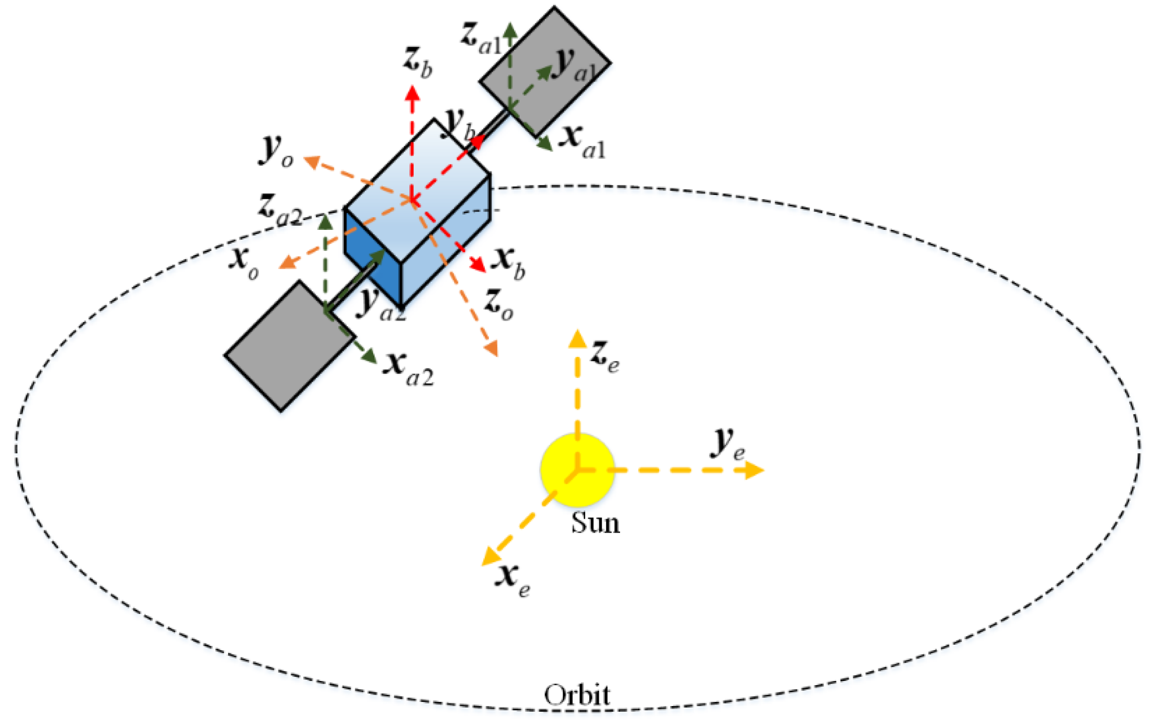
2. Spacecraft Model
2.1. Kinematics and Dynamics of Spacecraft
2.2. The Model of Solar Radiation Pressure Torque
3. Control Law Design
3.1. Control Scheme Based on Dual Mode MPC
3.2. Feasibility and Stability Analysis
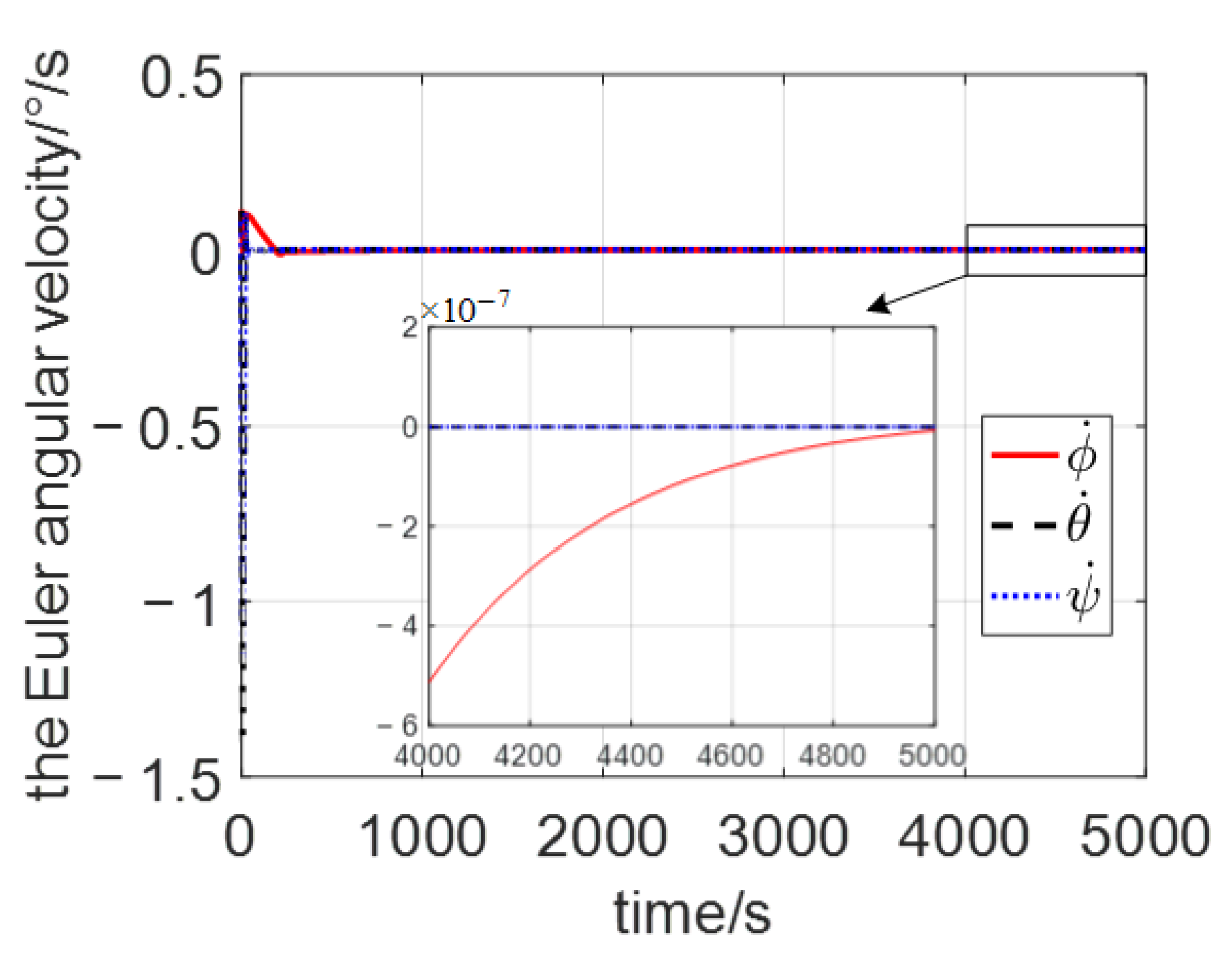
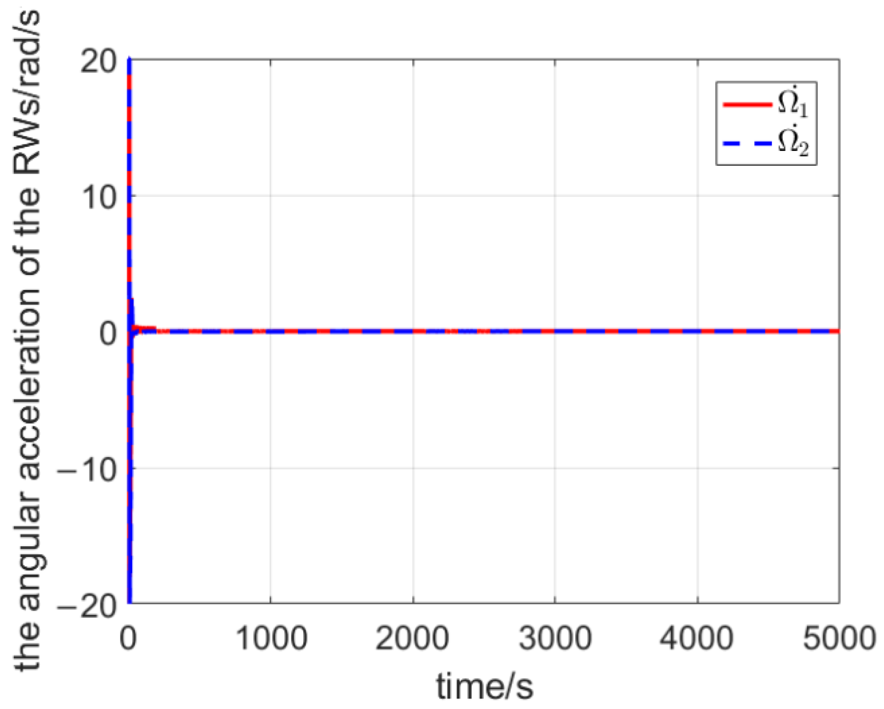
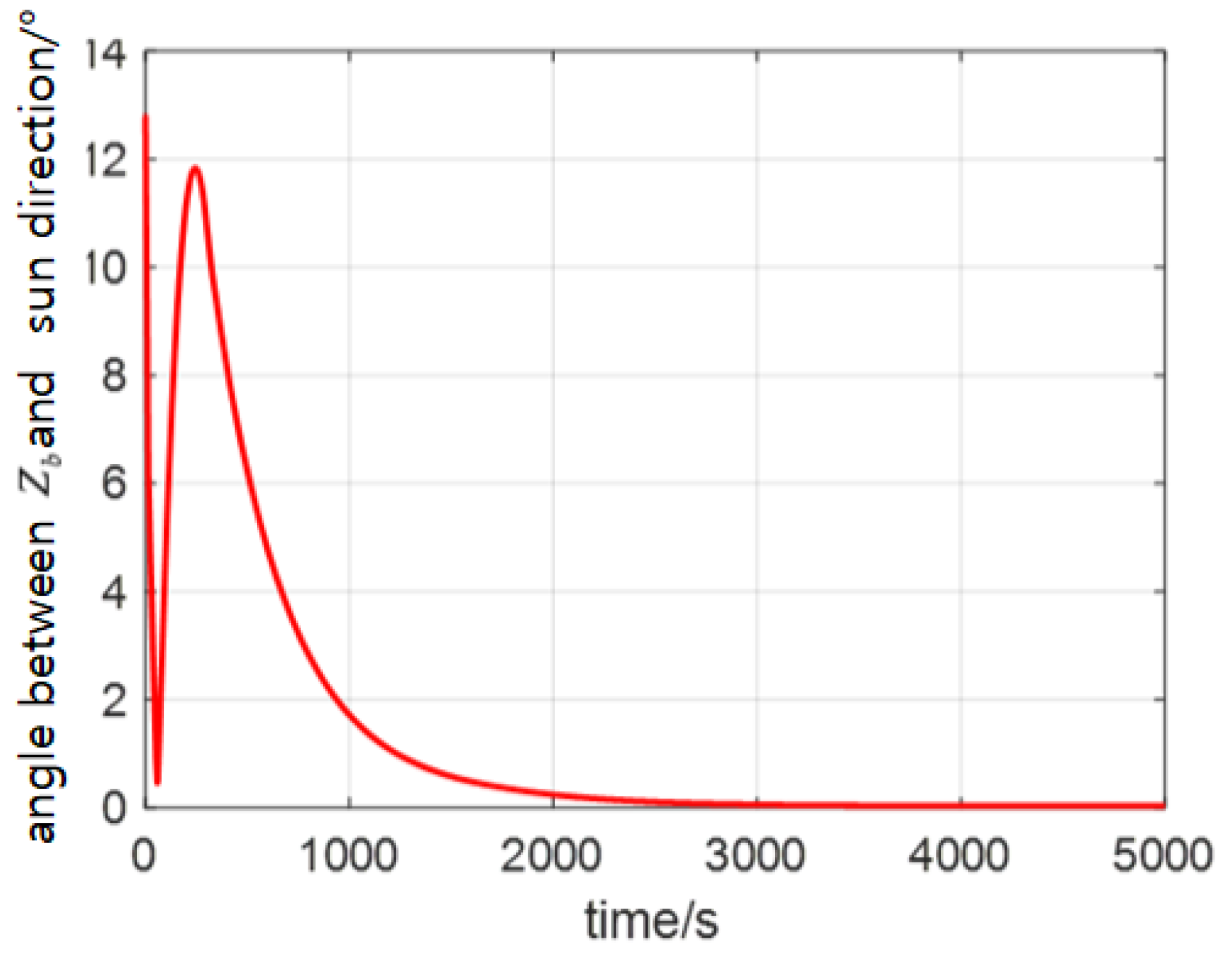
4. Simulation Results
5. Conclusions
Author Contributions
Funding
Data Availability Statement
Conflicts of Interest
References
- O’Donnell, J.R.; Andrews, S.; Ericsson-Jackson, A.; Flatley, T.; Ward, D.; Bay, P. Backup Attitude Control Algorithms for the MAP Spacecraft. In Flight Mechanics Symposium, Proceeding of a Conference Sponsored and Held at NASA Goddard Space Flight Center; Lynch, J.P., Ed.; NASA Goddard Space Flight Center: Greenbelt, MD, USA, 1999; pp. 391–405. [Google Scholar]
- Starin, S.R.; O’Donnell, J.R. Development of a Two-Wheel Contingency Mode for the MAP Spacecraft. In Proceedings of the AIAA Guidance, Navigation, and Control Conference and Exhibit, Monterey, CA, USA, 5–8 August 2002; p. 4584. [Google Scholar]
- Crouch, P. Spacecraft attitude control and stabilization: Applications of geometric control theory to rigid body models. IEEE Trans. Autom. Control 1984, 29, 321–331. [Google Scholar] [CrossRef]
- Kruk, J.W.; Class, B.F.; Rovner, D.; Westphal, J.; Ake, T.B.; Moos, H.W.; Roberts, B.A.; Fisher, L. FUSE In-Orbit Attitude Control with Two Reaction Wheels and No Gyroscopes. In Proceedings of the Future EUV/UV and Visible Space Astrophysics Missions and Instrumentation, SPIE, Waikoloa, HI, USA, 2003; pp. 274–285. [Google Scholar]
- Sahnow, D.J.; Kruk, J.W.; Ake, T.B.; Andersson, B.G.; Berman, A.; Blair, W.P.; Boyer, R.; Caplinger, J.; Calvani, H.; Civeit, T.; et al. Operations with the new FUSE observatory: Three-axis control with one reaction wheel. In Proceedings of the Space Telescopes and Instrumentation II: Ultraviolet to Gamma Ray, SPIE Astronomical Telescopes + Instrumentation, Orlando, FL, USA, 7 June 2006; p. 626602. [Google Scholar]
- Thomas, T. Experiences with the BIRD Magnetic Coil System for Wheel Desaturation, Satellite Rate Damping and Attitude Control-the Concept of Virtual Wheel Systems. In Proceedings of the 5th Symposium on Small Satellites for Earth Observation, Berlin, Germany, 4–8 April 2005; pp. 361–368. [Google Scholar]
- Krishnan, H.; McClamroch, H.; Reyhanoglu, M. Attitude Stabilization of a Rigid Spacecraft Using Two Momentum Wheel Actuators. J. Guid. Control Dynamics. 1995, 18, 256–263. [Google Scholar] [CrossRef]
- Kim, S.; Kim, Y. Spin-Axis Stabilization of a Rigid Spacecraft Using Two Reaction Wheels. J. Guid. Control Dyn. 2001, 24, 1046–1049. [Google Scholar]
- Horri, N.M.; Hodgart, S. Attitude Stabilization of an Underactuated Satellite Using Two Wheels. IEEE Aerosp. Conf. 2003, 6, 2629–2635. [Google Scholar]
- Boyer, F.; Alamir, M. Further Results on the Controllability of a Two-wheeled Satellite. J. Guid. Control Dyn. 2007, 30, 611–619. [Google Scholar] [CrossRef]
- Horri, N.M.; Palmer, P. Practical Implementation of Attitude-Control Algorithms for an Underactuated Satellite. J. Guid. Control Dyn. 2012, 35, 40–50. [Google Scholar]
- Gui, H.C.; Jin, L.; Xu, S.J. Attitude Maneuver Control of a Two-Wheeled Spacecraft With Bounded Wheel Speeds. Acta Astronautica. 2013, 88, 98–107. [Google Scholar] [CrossRef]
- Avanzini, G.; Zavoli, A.; Matteis, G.D.; Giulietti, F. Single Axis Pointing for Underactuated Spacecraft with a Residual Angular Momentum. Aerosp. Sci. Technol. 2022, 124, 107512. [Google Scholar] [CrossRef]
- Ousaloo, S.H. Attitude Acquisition from an Arbitrary Tumbling State Using Two Skewed Reaction Wheels. Aerosp. Sci. Technol. 2018, 72, 84–94. [Google Scholar]
- Han, C.Y.; Pechev, A.N. Time-Varing Nonlinear Designs for Underactuated Attitude Control with Two Reaction Wheels. In Proceedings of the 9th Biennial ASME Conference on Engineering Systems Design and Analysis, Haifa, Israel, 7–9 July 2008. [Google Scholar]
- Nadafi, R.; Kabganian, M. Robust nonlinear attitude tracking control of an underactuated spacecraft under saturation and time-varying uncertainties. Eur. J. Control 2022, 63, 133–142. [Google Scholar] [CrossRef]
- Siahpush, A.; Sexton, A. A Study for Semi-Passive Gravity Gradient Stabilization of Small Satellites. In Proceedings of the USU Conference on Small Satellites, Logan, UT, USA, 7–9 October 1987. [Google Scholar]
- Avanzini, G.; Angelis, L.E.; Giulietti, F. Two-Timescale Magnetic Attitude Control of Low-Earth-Orbit Spacecraft. Aerosp. Sci. Technol. 2021, 116, 106884. [Google Scholar] [CrossRef]
- Alger, M.; Ruiter, D.A. Magnetic Spacecraft Attitude Stabilization with Two Torquers. Acta Astronautica. 2022, 192, 157–167.g. [Google Scholar] [CrossRef]
- Zeng, J.Q. Application of Aerodynamic Torque in Attitude Control of Ultra-low Orbit Satellite. Master’s Thesis, Harbin Institute of Technology, Harbin, China, 2009. [Google Scholar]
- Forbes, J.R.; Damaren, C.J. Geometric Approach to Spacecraft Attitude Control Using Magnetic and Mechanical Actuation. J. Guid. Control Dyn. 2010, 33, 590–595. [Google Scholar] [CrossRef]
- Angelis, L.E.; Giulietti, F.; Ruiter, H.J.A.; Avanzini, G. Spacecraft Attitude Control Using Magnetic and Mechanical Actuation. J. Guid. Control Dyn. 2016, 39, 564–573. [Google Scholar] [CrossRef]
- Ousaloo, S.H. Globally Asymptotic Three-axis Attitude Control for A Two-Wheeled Small Satellite. Acta Astronaut. 2019, 157, 17–28. [Google Scholar] [CrossRef]
- Keshtkar, N.; Keshtkar, S.; Moreno, A.J.; Poznyak, A.; Kojima, H. LMI-Based Sliding Mode Control of an Underactuated Control Moment Gyroscope System. IFAC Pap. Line 2018, 51, 291–296. [Google Scholar] [CrossRef]
- Lee, K.W.; Singh, S.N. Three-axis L1 adaptive attitude control of spacecraft using solar radiation pressure. Proc. Inst. Mech. Eng. Part G J. Aerosp. Eng. 2015, 229, 407–422. [Google Scholar] [CrossRef]
- Lee, K.W.; Singh, S.N. A Higher-Order Sliding Mode Three-Axis Solar Pressure Satellite Attitude Control System. J. Aerosp. Eng. 2016, 29, 04015019. [Google Scholar] [CrossRef]
- Cowen, R. The wheels come off Kepler. Nature 2013, 497, 417–418. [Google Scholar] [CrossRef][Green Version]
- Petersen, C.D.; Leve, F.; Flynn, M.; Kolmanovsky, I. Recovering Linear Controllability of an Underactuated Spacecraft by Exploiting Solar Radiation Pressure. J. Guid. Control Dyn. 2016, 39, 826–837. [Google Scholar] [CrossRef]
- Thomas, S.; Michael, P.; Wie, B.; Murphy, D. AOCS performance and stability validation for large flexible solar sail spacecraft. American Institute of Aeronautics and Astronautics. In Proceedings of the 41st AIAA/ASME/SAE/ASEE Joint Propulsion Conference & Exhibit, Tucson, AZ, USA, 10–13 July 2005; p. 3926. [Google Scholar]
- Wie, B.; Murphy, D. MicroPPT-based secondary/backup ACS for a 160-m, 450-kg solar sail spacecraft. American Institute of Aeronautics and Astronautics. In Proceedings of the 41st AIAA/ASME/SAE/ASEE Joint Propulsion Conference & Exhibit, Tucson, AZ, USA, 10–13 July 2005; p. 3724. [Google Scholar]
- Funase, R.; Shirasawa, Y.; Mimasu, Y.; Mori, O.; Tsuda, Y.; Saiki, T.; Kawaguchi, J.I. On-orbit verification of fuel-free attitude control system for spinning solar sail utilizing solar radiation pressure. Adv. Space Res. 2011, 48, 1740–1746. [Google Scholar] [CrossRef]
- Lei, J. Study on Attitude Dynamics and Control of Spacecraft Using Angular Momentum Exchange Devices. Ph.D. Thesis, Beihang University, Beijing, China, 2009. [Google Scholar]
- Mclnnes, C.R. Solar Sailing; Springer London: London, UK, 1999. [Google Scholar]
- Chen, H.; Allgöwer, F. A Quasi-Infinite Horizon Nonlinear Model Predictive Control Scheme with Guaranteed Stability. Automatica 1998, 34, 1205–1217. [Google Scholar] [CrossRef]
- Mayne, D.Q.; Rawlings, J.B.; Rao, C.V.; Scokaert, P.O. Constrained model predictive control: Stability and optimality. Automatica 2000, 36, 789–814. [Google Scholar] [CrossRef]


Publisher’s Note: MDPI stays neutral with regard to jurisdictional claims in published maps and institutional affiliations. |
© 2022 by the authors. Licensee MDPI, Basel, Switzerland. This article is an open access article distributed under the terms and conditions of the Creative Commons Attribution (CC BY) license (https://creativecommons.org/licenses/by/4.0/).
Share and Cite
Jin, L.; Li, Y. Model Predictive Control-Based Attitude Control of Under-Actuated Spacecraft Using Solar Radiation Pressure. Aerospace 2022, 9, 498. https://doi.org/10.3390/aerospace9090498
Jin L, Li Y. Model Predictive Control-Based Attitude Control of Under-Actuated Spacecraft Using Solar Radiation Pressure. Aerospace. 2022; 9(9):498. https://doi.org/10.3390/aerospace9090498
Chicago/Turabian StyleJin, Lei, and Yingjie Li. 2022. "Model Predictive Control-Based Attitude Control of Under-Actuated Spacecraft Using Solar Radiation Pressure" Aerospace 9, no. 9: 498. https://doi.org/10.3390/aerospace9090498
APA StyleJin, L., & Li, Y. (2022). Model Predictive Control-Based Attitude Control of Under-Actuated Spacecraft Using Solar Radiation Pressure. Aerospace, 9(9), 498. https://doi.org/10.3390/aerospace9090498