Abstract
The Martian topography needs to be investigated in greater detail for human habitations, and this can be accomplished faster using unmanned aerial vehicles (UAVs). In this regard, the RQ-11B Raven appears suitable for remote sensing and topography-mapping applications on Mars, due to its popularity in surveillance and reconnaissance applications on Earth. As a result, this study investigates the flight of this UAV in the Martian atmosphere with the assumptions that it employs an NACA S7012 airfoil and its electric propulsion technology is replaced with a four-stroke oxy-methane fueled Saito FG-11 internal combustion engine (ICE). This ICE is estimated to supply 367.8 W resulting in an engine speed of 6891 revolutions per minute. Based on this speed, the UAV must fly at least 72 m/s (Re = 18,100) at a 5° angle of attack to support flight under calm conditions. To achieve this speed will be difficult; thus, a weather balloon or German V1-style launch system should be employed to launch the UAV successfully. Furthermore, the UAV must operate below 165 m/s (Re = 41,450) to prevent transonic conditions. Finally, the vehicle’s fuel and oxidizer tanks can be refueled using an in situ methane and oxygen production system, enabling its sustainable use on Mars.
1. Introduction
As manned flight to Mars draws closer, the resources needed to support expeditions become more important to consider. One such resource is a reliable method to complete reconnaissance of the Martian surface. With respect to rovers, ground vehicles are inherently not well suited for aerographic exploration due to the rough and abrasive terrain of Mars [1]. In addition, while rovers include high-definition cameras, have the ability to take ground samples, and are self-sufficient, they have reduced capability in the speed and magnitude of their exploration. Instead, surveillance efforts could be expedited with the use of unmanned aircrafts. In this area, the Ingenuity rotorcraft was the first such aircraft to demonstrate unmanned flight by completing several successful excursions from the Perseverance rover [2]. While this was impressive, there remains significant ground to cover, both physically and metaphorically. Instead of a low-speed helicopter, the implementation of a fixed-wing scouting aircraft on Mars could efficiently complete surface exploration, providing a more comprehensive view of the surface.
Since a fixed-wing plane will weigh on Mars approximately 1/3rd of the weight of the same plane on Earth, and so overcoming gravity is less of a challenge. However, given an air density that is 2% of the that on Earth, generating lift will be difficult. In addition, the speed of sound on Mars is around 60% of the speed of sound on Earth, thus transonic conditions are more readily reached, significantly restricting the flight envelope. These challenging conditions require substantial attention when considering a fixed-wing plane for Mars. As discussed in a recent review article by Sharma et al. [3], designs for unmanned aerial vehicles (UAVs) to achieve flight on Mars under such demanding circumstances have been in production since the late 1970s, starting with the Mini-Sniffer aircraft [4]. Overall, UAVs have been proposed with masses between 2.14 × 10⁻⁴ kg and 300 kg and wingspans ranging from 0.35 m to 21 m. A comparison of the UAV power supplies carried out by Sharma et al. found the use of solar power or lithium manganese oxide batteries, but did not mention the potential to use hydrazine as a monopropellant or as a bipropellant in combination with other fuels [5,6]. Interestingly, there is no mention of the use of internal combustion engines (ICEs) as a power source, even though research by the National Aeronautics and Space Administration (NASA) has investigated the feasibility of creating a Mars ICE, fueled by mixtures of methane, carbon dioxide, and oxygen [7].
Recent efforts highlighting the in situ potential of fabricating liquid methane and liquid oxygen on Mars [8] have indicated that it is thermodynamically possible to generate these compounds using water from the regolith and carbon dioxide from the atmosphere. Thus, separate tanks on board the UAV would supply both the fuel and the oxidant to power an ICE, and ensure full functionality in the oxygen-poor atmosphere along with refueling capability on the surface. As a result, our current study analyzes a comparatively small UAV powered by an ICE for flight on Mars. This analysis was competed through the lens of the RQ-11B Raven, shown in Figure 1 [9], which is the most common UAV in the United States (US) military [10]. Since this plane fulfills the role of aerial surveillance and reconnaissance for military operations on Earth, it is an ideal starting point for a small camera-carrying aircraft on Mars. While the Raven is normally propelled using an electric motor powered by lithium-ion batteries [11], the analysis presented assumes that the Raven would operate utilizing the Saito FG-11 internal combustion engine (ICE) [12], which is one of the smallest four-stroke model airplane engines on the market. Future efforts to predict fuel flow rates and flight time based on tank size will be accomplished using a simplified model for oxy-methane combustion [13] and an ICE model [9].
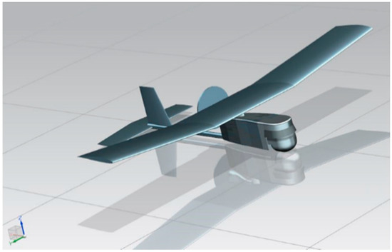
Figure 1.
Three-Dimensional Computer Aided Drafting (CAD) model of the RQ-11B Raven, Reprinted from Energy Conversion and Management, 207, Depcik, C., Cassady, T., Collicott, B., Burugupally, S. P., Li, X., Alam, S. S., Arandia, J. R., and Hobeck, J. Comparison of lithium ion Batteries, hydrogen fueled combustion engines, and a hydrogen fuel cell in powering a small Unmanned Aerial Vehicle, 112514, Copyright 2020, with permission from Elsevier [9].
This study began by detailing the environmental conditions seen by the UAV on Mars. Subsequently, a simplified model of the coefficients of drag and lift were created based on the Raven’s assumed airfoil. Prior work analyzing the Saito FG-11 engine was then used to determine the power and engine speed. This resulted in a performance analysis of the UAV in the Martian atmosphere, followed by recommended design improvements that can enable more efficient flight.
2. Martian Environmental Conditions
Knowledge of Martian environmental conditions is critical for the correct design and performance analysis of the RQ-11B Raven. Thetwo primary differences between the aircraft environment on Earth and Mars are gravity and atmospheric density. The gravity on Mars is approximately 3/8th of the gravity on Earth; hence, less lift is needed on Mars for the same mass of aircraft. However, the atmosphere on Mars is about a hundred times less dense than that on Earth. As a result, less lift will be produced. Thus, any fixed-wing aircraft will have to fly faster on Mars than on Earth to create adequate lift. In addition, due to the low Martian atmospheric density, this faster speed will be a larger fraction of the speed of sound.
With respect to gravity (g), Hirt et al. determined that the average surface acceleration on Mars is 3.72076 m/s2 [14]. This gravity changes with location (h) and operational altitude (halt), respectively, as:
where rm is the mean radius of Mars (3389.500 km). Regarding the location, Morgan et al. stated that humans will set up colonies near places where water is likely to exist [15]. Based on their composite ice consistency model, the Arcadia Planitia-Phlegra Montes region near the North pole has an elevated chance of water-based ice. Reviewing the US Geological Survey topographic map of Mars, an elevation of around 7000 m below sea level can be found in this region [16].
An estimate of the atmosphere of Mars based on altitude was taken from the work of Ilich et al. [17], which supplied the pressure (p), density (ρ), and temperature (T) as functions of its areoid, as illustrated in Figure 2 and Figure 3, respectively. To find the speed of sound (c) on Mars:
involves determining the ratio of specific heats (k) and gas constant (RMars). The molecular mass of the atmosphere (MMars) was calculated from data obtained by the Curiosity Lander [18] and was found equal to 43.6203 g/mol. This results in a gas constant of 190.6 J/(kg × K).

Figure 2.
Martian atmospheric pressure and density with respect to altitude, adapted from [17].
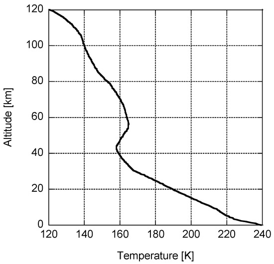
Figure 3.
Martian atmospheric temperature with respect to altitude, adapted from [17].
The ratio of specific heats (k = cp/cv) was calculated from constant pressure (cp) and constant volume (cv) parameters with cp fit to a second-order polynomial, based on data from Colonna et al. [19]:
and:
In the next section, a simplified model of the coefficients of drag and lift was generated based on the Reynolds (Re) number:
where l is the characteristic length, in this case the root chord of the wing that is equal to the wingspan (b) divided by the aspect ratio (AR), and V is the horizontal velocity of the UAV. Determination of this non-dimensional parameter also requires information about the dynamic viscosity (µ) of the atmosphere. These data were drawn from the final report by Colozza et al. [20], using the Jet Propulsion Laboratory (JPL) Mars atmospheric model at −20° latitude as illustrated in Figure 4.

Figure 4.
Viscosity of Martian atmosphere at −20° latitude using the JPL atmospheric model.
Investigating the wind speeds on Mars, Martínez et al. highlighted these data as functions of season and longitude, with one maximum value indicated at around 23 m/s [21]; however, Greeley et al. stated that for saltation to occur, wind speed must exceed 30 and 25 m/s for the northern and southern hemispheres, respectively [22]. Comparatively, the Mars weather and climate data from the InSight mission indicated an average wind speed of 5.46 +/− 0.92 m/s over the seasons [23]. However, given the higher likelihood of accidents happening when wind is present, our current study assumes that the UAV will only operate in calm conditions.
Because the density of the Martian atmosphere is comparatively thin at ground level and becomes thinner yet as altitude increases, as seen in Figure 2, it is prudent to keep the operating altitude of the UAV low to allow maximum lift at a minimal speed. On Earth, the Raven flies at an altitude between 30 and 152 m [24]. While the respective atmospheres are different, an operating altitude of 100 m was chosen as an approximate average of the Raven’s typical flight height. The atmospheric and gravitational properties of Mars at this altitude are shown in Table 1.

Table 1.
Martian environmental properties at halt = 100 m.
3. Reynolds Number Airfoil Consideration
The thin composition of the Martian atmosphere will result in low Re number values for the aircraft, even when travelling at speeds up to 200 m/s (Re = 51,709). Since this low Re number in flight can be problematic for the stability of the aircraft, it is pertinent to find data for the UAV within these lower Re number regions. In a previous study [9], examination of the Raven considered that the wings used the NACA S7012 airfoil. Reviewing the literature finds data for this airfoil at Re numbers of 31,306 [25], 50,000 [26], 60,000, 100,000, 200,000, and 300,000 [27,28]; interestingly, most of these data were for low-speed wind turbine applications. Unfortunately, it was not possible to distinguish the data at 50,000; hence, that data was not included in this study. In addition, a linear interpolation was accomplished using the coefficient of lift versus Angle of Attack (AoA) to estimate values at Re of 150,000 [28]. The resulting values of the coefficient of lift (Cl) as a function of the coefficient of drag (Cd) are presented in Figure 5; this airfoil’s lift and drag characteristics vary significantly as Reynolds numbers decrease to values below 100,000.
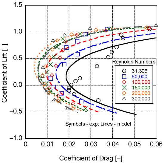
Figure 5.
S7012 Airfoil Cl and Cd data and model predictions over varying Reynolds numbers.
While it is possible to interpolate the data for coefficients of lift and drag as functions of AoA and Reynolds number, it was decided to instead find a physical model to calculate these parameters. In this regard, Liu indicated the existence of four potential models for flat-plate or thin-plate airfoils [29]:
- Newton’s sine-squared law
- Rayleign’s lift formula
- Kutta–Joukowski (K–J) theorem
- Viscous-flow lift formula
Newton’s sine-squared law follows an explanation based on conservation of momentum of lift, via momentum exchange of particles impinging on the surface. It underestimates both lift and drag, since it assumes the fluid consists of non-interacting solid particles, which should instead be treated as a continuum via the Navier–Stokes (N–S) equations. Rayleign’s lift formula is derived from the N–S equations after a conforming transformation, and endeavors to reconstruct the airfoil velocity field. While the developed field is applicable to drag, it underestimates lift since it does not include a vortex-lift mechanism. The K–J theorem includes circulation from which vorticity can be determined; thus, it results in a model for the lift coefficient that includes vortex lift in its derivation. Viscous flow can directly evaluate lift without circulation, through the relationship between surface pressure and skin friction. Of these models, the first three can be determined algebraically providing a simple estimation. Fitting the data at each Reynolds number found that the K–J theorem best matched the coefficient of lift versus AoA (), as shown in Figure 6, with R2 values ranging from 0.992 to 0.999. This is to be expected given the inclusion of vortex lift in its derivation, hence supplying a more physical interpretation of lift. The respective K–J expression equals:
where , , and are parameters fitted to the data using a Matlab-based optimization employing the fmincon function that minimizes the difference between the data and model. The angle of attack at zero lift, , was determined from the data. It is important to note that the use of this model is an issue for drag, since D’Alembert’s paradox for thin-airfoil theory results in zero drag.

Figure 6.
Use of K–J Theorem to match Cl as a function of AoA at each Re number.
Like the efforts shown in Figure 6, the Matlab fmincon optimization function was used to find the parameters D through O that minimized the difference between the model and the experimental data. The linear relationship was unable to capture the higher Cl values, while the quadratic relationship provided a better match to the point of the change in the slope as shown in Figure 7. This resulted in an overall R2 value equal to 0.988, and appears to be a reasonable assumption for the airfoil in the absence of specific Reynolds number data or more detailed models. The resulting values of the optimized coefficients are provided in Table 2.

Figure 7.
Use of K–J theorem to match Cl as a function of AoA with a quadratic Re number relationship.
Table 2.
Coefficients for the Cl quadratic Re number model.
While this was useful for evaluating individual Re numbers, it supplied little insight into the direct correlation between coefficient of lift and Re number. For a more predictive model, it was assumed that the coefficients (A, B, and C) and angle of attack at zero lift were all functions of the Re number. Two options were tried, linear and quadratic functions of Re:
With respect to the coefficient of drag, this can be directly generated as a function of Cl (e.g., Figure 5) or of the AoA. The latter was used for the modeling of Cd, since it can have a non-linear dependency on the AoA [30]; thus, an analogous model to Cl was generated:
with the parameters fitting similarly while using the same AoA model at zero lift:
Note that a third-order dependency on the AoA for the Cd did not appreciably improve the model results. In Table 2 and Table 3, there are coefficients that are near to zero. Since the Reynolds number varied from 31,306 to 300,000 and these coefficients were multiplied by , they were still pertinent for the model and helped to improve the model fit. For example, taking Equation (14) at a Reynolds number of 300,000: j = 2.7322, k · = −4.0632, and m · = 2.6649.
Table 3.
Coefficients for the Cd quadratic Re number model.
As illustrated in Figure 8, this simple model using the parameters provided in Table 3 was found to perform adequately when representing these data, with an overall R2 value of 0.905. Reviewing Figure 5, the model held well for higher Re numbers but did a less effective job at Re = 31,306. For the purposes of this effort, this was considered acceptable as a first-pass approximation for lift and drag of the NACA S7012 airfoil in the Martian atmosphere.

Figure 8.
Experimental and model Cd values as functions of Re numbers and AoA.
4. Engine Power and Speed
The Raven UAV, usually equipped with an electric motor and battery powertrain, was for the purposes of this study considered to be powered by a Saito FG-11 ICE fueled using pressurized methane and oxygen tanks. This ICE has a practical engine speed (Nr) of 2000 to 9500 revolutions per minute (rpm) with a stated maximum power of 735.5 W [12]. The engine manual also specifies that the ICE should use a 12′′ × 8′′ or 13′′ × 8′′ propeller (Dp).
According to Menon and Cadou [31], small ICEs generally only achieve 50–70% of their rated performance. As a conservative estimate, it was assumed that the engine would perform at 50% of its rated performance: 367.8 W. Recent efforts by Gray et al. supplied the air and fuel mass flow rates for this engine as functions of engine speed under propeller-based testing [32]. Using this information and assuming that the maximum power is achieved at an equivalence ratio of 1.1 [33], the average volumetric heating value of gasoline is 114,102 Btu/gal [34], the density of gasoline is 0.73 g/mL [35], and the engine runs at 20% thermal efficiency, a representative power versus engine speed plot was generated, as shown in Figure 9. Incorporating a linear curve fit allowed estimation of engine power based on speed, with an R2 value of 0.9998:

Figure 9.
Estimated Saito FG-11 ICE power as a function of engine speed.
Equation (15) estimated that the ICE will achieve 33.7% to 61.5% of its maximum engine power at the indicated speeds in Figure 9, which is in line with Menon and Cadou’s findings. At 367.8 W, the engine will be spin at approximately 6891 rpm. It is important to note that Alam et al. found oxy-methane combustion to be significantly more energetic in the absence of nitrogen to act as a diluent [13]. Thus, higher thermal efficiencies can be achieved, and this linear estimation would need to be revised after similar engine tests with methane and oxygen.
Since the engine speed is now known, the radial velocity of the propeller tip (Vr) can be calculated as:
From this information, the magnitude of the combined velocity of the propeller tip (Vtip) can be calculated using the Pythagorean theorem:
Subsequently, the Mach number of the propeller tip can be found for a range of 10 to 200 m/s of horizontal speed, and is provided in Figure 10 for both 12′′ × 8′′ and 13′′ × 8′′ propellers. Since transonic speeds begin at around 80% the speed of sound, these speeds should be avoided where performance characteristics would deteriorate rapidly [36]. This sets a horizontal speed limit of ~165 m/s and ~159 m/s for the 12′′ and 13′′ diameter propellers, respectively, as the Mach number of the propeller tip will be the limiting factor for airspeed of the total aircraft. Generally, selecting a larger propeller would be more advantageous to generate thrust in the low-density Martian atmosphere. However, as indicated in Figure 10, the larger the propeller size, the smaller the flight velocity envelope before transonic conditions are reached. On Earth, this would not be an issue as the lift force can be readily achieved at low speeds. On Mars, as described in the next section, significantly faster speeds are needed to achieve the required lift; thus, choosing the smaller 12” propeller allows a greater flight speed range.

Figure 10.
Propeller tip Mach number values as a function of UAV speed.
5. Performance Analysis of Raven RQ-11B
To understand the performance of the Raven UAV on Mars, an analysis of the aircraft was performed for level flight at constant velocity; i.e., when the thrust force (FT) is equal to the drag force (FD) in the aircraft x-direction for a body coordinate system:
The drag force can be further specified through the following:
where Af is the frontal area of the aircraft, Cd,lift is the induced drag coefficient, and Vwind is the velocity of the wind that is subtractive when opposing the forward motion of the aircraft. The induced drag coefficient is expressed as:
where eOS is the Oswald efficiency number.
Representative values, such as the aspect ratio and frontal area of the Raven, were pulled from prior analysis of the plane [9]. However, the specified mass in the earlier paper was incorrect since the power plant was replaced. The original power plant was an Aveox 27/26/7-AV 250 W DC electric motor plus battery pack [9]. The mass of this system is unknown, but the mass of the ICE replacement is known. The full Saito FG-11 system, including ignition system, carburetor, and muffler has a mass of 720 g. This mass combined with that of the two fuel tanks for methane and oxygen is likely to be greater than that of the electric motor and battery. However, due to the unknown mass of the original power plant, this analysis used the mass of the stock aircraft given in Table 4.
Table 4.
RQ-11B Raven salient characteristics.
The lift force was calculated as follows:
where the planform area (Ap) can be determined using the wingspan and aspect ratio:
The resulting drag and lift forces at a moderate AoA of 5° without wind are presented in Figure 11. At 72 m/s (Re = 18,100), enough lift was found to be generated to overcome the weight of the UAV (7.1 N). Given the upper limit of 165 m/s (Re = 41,450), there does appear to be a regime whereby UAV flight can be supported on Mars. However, the respectively low Reynolds numbers encountered, and the corresponding inaccuracy at these values of the simple model in Section 3, warrant further consideration. Interestingly, drag forces remained less than 1 N, highlighting that drag is not a significant concern for flight on Mars. This is true even if a 30 m/s wind is opposing the flight motion, as drag would grow by around 0.3 N at 200 m/s. In contrast, a 30 m/s wind-aided flight would require a flight speed of ~102 m/s to support sufficient lift. Furthermore, any increase in mass due to the ICE and fuel tanks in addition to the original UAV design will require an increase in airspeed to maintain lift. To illustrate, Figure 12 provides a parametric study of the influence of mass on the speed required to maintain lift. Obviously, decreasing the mass of the vehicle will make achieving flight easier, as a 50% reduction in mass requires 29% less speed at 51 m/s to remain airborne. However, a 50% increase in mass only needs to increase speed by 22% at 88 m/s to stay in the air. This remains under transonic conditions at around 118 m/s, with a 30 m/s wind aiding the flight. This indicates that even with an appreciable increase in mass, flight still appears possible.

Figure 11.
Drag force, lift force, and Reynolds number at an AoA of 5 degrees.

Figure 12.
Parametric study of velocity needed to achieve flight as a function of the overall vehicle mass.
While the force analysis shows a prospective range, it is important to check the propeller efficiency that would be needed at each speed. Given the thin atmosphere of Mars, it might not be possible to reach similar propeller efficiencies as in the Earth’s atmosphere. Calculation of this parameter began by first finding the thrust (CT) and power (CP) coefficients, respectively:
with the propeller efficiency () dependent on these parameters,
and the advance ratio (J):
Plotting the required propeller efficiency as a function of horizontal velocity, as in Figure 13, indicates that the propeller efficiency must be at least 21.3% to achieve flight at 165 m/s. Overall, given the assumptions presented, it seems feasible to fly a UAV on Mars; however, there are limitations to this analysis and this UAV design in general.

Figure 13.
Required propeller efficiency to maintain flight at an AoA of 5 degrees.
6. Design Considerations
The design of the airfoil has been found to be one of the more critical facets for ensuring flight on Mars. In this area, Oyama and Fujii utilized a two-dimensional thin-layer Reynolds-averaged Navier–Stokes solver and an evolutionary computer algorithm to manipulate the spline point for generating an airfoil at an AoA of 2°, while considering the viscous effects of the Martian atmosphere [37]. Their goal was to optimize the lift to drag ratio, and they found that an optimized airfoil would be extraordinarily thin with little to no additional thickness near the leading edge. This airfoil, shown in Figure 14, would also have a significant camber to enhance expansion under the airfoil and compression above the airfoil. However, an airfoil of this shape does not lend itself to a structurally robust wing construction. It may have some limited use with the application of shaped composites, such as carbon fiber in a stub or a strutted wing configuration.

Figure 14.
Optimized airfoil for Martian aircraft with pressure contour lines indicated [37].
Subsequent work by Shimoyama et al. expanded on this effort by using an evolutionary algorithm and a multi-objective six-sigma approach [38]. Their findings show that an airfoil with a smaller maximum camber can obtain a more desirable lift to drag ratio. In addition, greater curvature at the location of the shock wave will provide a more robust pitching moment as the Mach number varies.
The need to design for low Reynolds numbers on Mars was considered by Anyoji et al. [39], who tested the performance of an Ishii airfoil and the effectiveness of an elevator with Reynolds numbers between 10,000 and 33,000. The Ishii airfoil was chosen for its advantageous performance characteristics in low Reynolds-number flows. It has a sharp leading edge that fixes the separation point and improves the Reynolds-number dependency during performance. In addition, its flat upper surface reduces the separation region while its camber allows it to generate greater lift than a symmetric airfoil. Performance remained steady against changes in the Reynolds number, and for deflections of less than 5° the elevator did not significantly affect the pitching moment of the aircraft. It was stated that using a thinner airfoil for the horizontal tail, such as a 1.3% flat plate or a NACA 0006, improved the coefficient of lift and the pitching moment effectiveness of the elevator. Bcause thinner airfoils have higher lift slopes, the effectiveness of the elevator was more pronounced as a component of the aircraft pitching moment. It was found that the tail airfoil should be as thin as possible to maximize lift slope, while allowing sufficient space for the control surface servos.
Thus, thin cambered airfoils appear advantageous, such as the Eppler 376, 377, or 378, all of which feature a more bulbous leading edge that could hold a spar or spar-like structure. Koning et al. investigated helicopter rotors, and their efforts provide some insight into airflow behavior around cambered and uncambered airfoils at a range of AoA and Reynolds numbers pertinent to the atmosphere of Mars [40]. Such airfoils would enable an aircraft to reach the required lift at lower speeds and angles of attack, creating less overall drag. These lower speeds would be advantageous for taking detailed photographs of the surface. In addition, this would lower overall power requirements and decrease fuel consumption, and so increase the potential flight time of missions.
Another method to improve lift characteristics would be to increase the span of the wings. Due to the reduced gravity, wing length can be extended without extensive structural modifications. This would boost wing lift without significantly increasing weight. Like the airfoil, this would allow a reduction of speed and an increase in potential flight time. Here, Liu et al. found that the ratio of propeller disk area to wing area is an important limiting factor [36].
6.1. Takeoff and Landing
On Earth, a ground crew launches the Raven by hand. While this might be possible on Mars, it is unlikely that a ground crew could create enough velocity for the aircraft to lift itself. Liu et al. additionally pointed out the difficulty generating the thrust needed to accelerate to an efficient cruising speed [36].
One solution shown in Figure 15 is to use a weather-balloon-style launcher that would raise the aircraft into the sky and then release it, allowing the aircraft to reach sufficient velocity while losing altitude until it could eventually keep itself aloft. Fastening this balloon to the ground would allow it to be lowered or raised on command. This system would also benefit from the high surface temperatures on Mars during the day, allowing the heating of gases inside the balloon; thus, creating a pseudo hot-air balloon apparatus.

Figure 15.
Balloon launch concept for a UAV.
Another potential launch method is via a ground-based launcher like the system created for the German V-1 flying bomb. Such a device need not be technically complicated, as the V-1 was launched using compressed steam. However, this launcher would need to attach to the aircraft in such a way that the acceleration gained on launch would not affect the structural integrity of the aircraft. This acceleration could also be spread over a longer launcher, allowing time for the aircraft to get up to speed.
The Raven lands on Earth by entering a high AoA near the ground, stalling the aircraft and significantly decreasing velocity. The aircraft then simply falls to the ground and breaks apart to distribute landing forces. At low cruising speeds on Earth, this method is viable, but will be significantly less so when the aircraft must transition from flight at 70+ m/s. An alternative system could be an onboard parachute for recovery. This could be contained within the aircraft and deployed over a recovery zone when fuel is depleted. The aircraft could then be put into a slow vertical descent where the break-apart feature would be viable for landing.
6.2. Sustainable Aircraft Operation on Mars
Long-term use of the proposed aircraft on Mars will require a continuous supply of methane (fuel) and oxygen. Research shows that liquid methane and liquid oxygen can both be fabricated on Mars using the planet’s carbon dioxide-rich atmosphere and icy regolith [41,42,43,44]. Recently, a second-law-based thermodynamic analysis by Alam et al. [8] showed that the achievable mass flow rates of methane and oxygen generated in situ can potentially refuel rockets on Mars within 16 months and so achieve NASA goals. Since the fuel and oxidizer requirements of the UAV analyzed should be significantly smaller than those of a rocket, it may be possible to sustain its long-term operation in Martian conditions. A key challenge will be maintaining the storage conditions of liquid methane and liquid oxygen tanks, estimated at 112.6 K and 93.0 K, respectively, while minimizing leakage. The Martian atmospheric temperature is significantly colder than Earth (seasonally between 197 K to 280 K [45]), so less energy will be needed to support these temperatures. These tank pressures have been calculated to be 1.093 × 10⁵ Pa and 1.352 × 10⁵ Pa, respectively, and there exists a positive pressure gradient for filling used UAV tanks assumed to be at human habitation atmospheric conditions (minimum 52.67 kPa [46]). In addition, allowing the tanks to warm up slightly would ensure a greater pressure differential for refilling. Finally, with proper maintenance, ICE- and lithium-ion battery (LIB)-powered vehicles are each expected to last for 200,000 miles (321,869 km) [47,48]. While both options significantly exceed the energy density of solar panels for powering UAVs, LIBs lose capacity with each cycle, whereas ICEs largely maintain their capabilities over their entire lifetime. This would ensure that the UAV retains its flight time during its existence.
7. Conclusions
The use of unmanned aerial vehicles on Mars, such as the US military’s RQ-11B Raven, could provide a larger surface exploration zone. However, under calm conditions, the Raven would have to fly in a flight speed envelope of approximately 72 to 165 m/s to stay aloft at an altitude of 100 m above the surface. Unfortunately, the low Reynolds numbers characteristic of the Martian atmosphere cause significant concern with respect to the stability of the aircraft and the model predictions. Thus, research is needed on the performance of airfoils at these low Reynolds numbers (20,000–60,000). Much of the current body of measured airfoil data is not applicable, simply because aircraft on Earth do not fly at the corresponding low velocities. Interestingly, the data found for the Raven’s airfoil was captured using wind turbine blades, a significantly different application than on the wing of an aircraft.
Despite the daunting nature of flying an aircraft in the virtually nonexistent atmosphere of Mars, it does appear plausible. The Raven, an aircraft designed exclusively for terrestrial flight, could conceivably fly on Mars with only minor modifications. The increasing variety of manufacturing methods for lightweight fiber-matrix composites, as well as other high strength-to-weight materials, can make the design of such an aircraft easier. Powering the UAV using an ICE fueled by tanks of methane and oxygen generated from in situ resource gathering could result in a sustainable system. Overall, the structure, aerodynamics, and propulsion system would all have to function at high efficiencies to minimize weight and maximize lift.
Author Contributions
Conceptualization, C.D.; methodology, S.A.R. and A.E.W.; software, S.A.R. and A.E.W.; validation, S.A.R., A.E.W. and C.D.; formal analysis, S.A.R., A.E.W. and C.D.; investigation, S.A.R., A.E.W., A.A., S.S.A. and C.D.; resources, S.A.R., A.E.W., A.A., S.S.A. and C.D.; data curation, S.A.R. and C.D.; writing—original draft preparation, S.A.R.; writing—review and editing, S.A.R., A.E.W., S.S.A. and C.D.; visualization, C.D.; supervision, C.D.; project administration, C.D.; funding acquisition, C.D. All authors have read and agreed to the published version of the manuscript.
Funding
This work was supported by the National Aeronautics and Space Administration via grant number 80NSSC19M0042.
Conflicts of Interest
The authors declare no conflict of interest. The funders had no role in the design of the study; in the collection, analyses, or interpretation of data; in the writing of the manuscript, or in the decision to publish the results.
References
- Ferguson, D.C.; Kolecki, J.C.; Siebert, M.W.; Wilt, D.M.; Matijevic, J.R. Evidence for Martian electrostatic charging and abrasive wheel wear from the Wheel Abrasion Experiment on the Pathfinder Sojourner rover. J. Geophys. Res. Planets 1999, 104, 8747–8759. [Google Scholar] [CrossRef]
- Davenport, C. NASA’s Mars Helicopter Was Supposed to Fly Five Times. It’s Flown 28. Available online: https://www.washingtonpost.com/technology/2022/05/13/nasa-ingenuity-mars-helicopter-perseverance/ (accessed on 4 March 2022).
- Sharma, M.; Gupta, A.; Gupta, S.K.; Alsamhi, S.H.; Shvetsov, A.V. Survey on Unmanned Aerial Vehicle for Mars Exploration: Deployment Use Case. Drones 2022, 6, 4. [Google Scholar] [CrossRef]
- Reed, R.D. High-Flying Mini-Sniffer RPV-Mars Bound. Astronaut. Aeronaut. 1978, 16, 26–39. [Google Scholar]
- Lafleur, J.; Olds, J.; Braun, R. Daedalon: A Revolutionary Morphing Spacecraft Design for Planetary Exploration. In Proceedings of the 1st Space Exploration Conference: Continuing the Voyage of Discovery, Orlando, FL, USA, 30 January–1 February 2005. [Google Scholar] [CrossRef]
- Braun, R.D.; Wright, H.S.; Croom, M.A.; Levine, J.S.; Spencer, D.A. Design of the ARES Mars Airplane and Mission Architecture. J. Spacecr. Rocket. 2006, 43, 1026–1034. [Google Scholar] [CrossRef]
- Bui, H.; Coletta, C.; Debois, A. Mars Methane Engine; National Aeronautics and Space Administration: Washington, DC, USA, 1994; NASA-CR-197205.
- Alam, S.S.; Depcik, C.; Burugupally, S.P.; Hobeck, J.; McDaniel, E. Thermodynamic modeling of in-situ rocket propellant fabrication on Mars. iScience 2022, 25, 104323. [Google Scholar] [CrossRef]
- Depcik, C.; Cassady, T.; Collicott, B.; Burugupally, S.P.; Li, X.; Alam, S.S.; Arandia, J.R.; Hobeck, J. Comparison of lithium ion Batteries, hydrogen fueled combustion Engines, and a hydrogen fuel cell in powering a small Unmanned Aerial Vehicle. Energy Convers. Manag. 2020, 207, 112514. [Google Scholar] [CrossRef]
- Military News. Pentagon Plans for Cuts to Drone Budgets. Available online: https://www.military.com/dodbuzz/2014/01/02/pentagon-plans-for-cuts-to-drone-budgets (accessed on 6 February 2022).
- Carey, S.B.; Carey, S.B. Increasing the Endurance and Payload Capacity of Unmanned Aerial Vehicles with Thin-Film Photovoltaics. Master’s Thesis, Naval Postgraduate School, Monterey, CA, USA, 2014. [Google Scholar]
- Saito. Saito FG-11 4-Stroke Gasoline Single Engine Operating Instructions. Available online: https://www.horizonhobby.com/on/demandware.static/Sites-horizon-us-Site/Sites-horizon-master/default/Manuals/SAIEG11-Manual.pdf (accessed on 10 January 2022).
- Alam, S.S.; Rosa, S.W.; Depcik, C.; Preetham Burugupally, S.; McDaniel, E.; Hobeck, J.D. Modification of the Wiebe function for methane-air and oxy-methane- based spark-ignition engines. Fuel 2021, 303, 121218. [Google Scholar] [CrossRef]
- Hirt, C.; Claessens, S.J.; Kuhn, M.; Featherstone, W.E. Kilometer-resolution gravity field of Mars: MGM2011. Planet. Space Sci. 2012, 67, 147–154. [Google Scholar] [CrossRef]
- Morgan, G.A.; Putzig, N.E.; Perry, M.R.; Sizemore, H.G.; Bramson, A.M.; Petersen, E.I.; Bain, Z.M.; Baker, D.M.H.; Mastrogiuseppe, M.; Hoover, R.H.; et al. Availability of subsurface water-ice resources in the northern mid-latitudes of Mars. Nat. Astron. 2021, 5, 230–236. [Google Scholar] [CrossRef]
- United States Geological Survey. Topographic Map of Mars. Available online: https://pubs.usgs.gov/imap/i2782/i2782_sh1.pdf (accessed on 24 February 2022).
- Ilich, Z.; Grossir, G.; Paris, S.; Chazot, O. Review of the VKI Longshot Hypersonic Tunnel Operation for Martian Entries. In Proceedings of the AIAA Scitech 2019 Forum, San Diego, CA, USA, 7–11 January 2019. [Google Scholar] [CrossRef]
- Mahaffy, P.R.; Webster, C.R.; Atreya, S.K.; Franz, H.; Wong, M.; Conrad, P.G.; Harpold, D.; Jones, J.J.; Leshin, L.A.; Manning, H.; et al. Abundance and Isotopic Composition of Gases in the Martian Atmosphere from the Curiosity Rover. Science 2013, 341, 263–266. [Google Scholar] [CrossRef]
- Colonna, G.; D’Angola, A.; Laricchiuta, A.; Bruno, D.; Capitelli, M. Analytical Expressions of Thermodynamic and Transport Properties of the Martian Atmosphere in a Wide Temperature and Pressure Range. Plasma Chem. Plasma Process. 2012, 33, 401–431. [Google Scholar] [CrossRef]
- Colozza, A.; Jenkins, P.; Smith, C.; Deacey, T.; Shahinpoor, M.; Isaac, K.; Olinger, D.; Day, A.; Robbins, L.; DalBello, T. Final Report on Solid State Aircraft Phase II Project. 2005. Available online: http://www.niac.usra.edu/files/studies/final_report/836Colozza.pdf (accessed on 26 July 2022).
- Martínez, G.M.; Newman, C.N.; De Vicente-Retortillo, A.; Fischer, E.; Renno, N.O.; Richardson, M.I.; Fairén, A.G.; Genzer, M.; Guzewich, S.D.; Haberle, R.M.; et al. The Modern Near-Surface Martian Climate: A Review of In-situ Meteorological Data from Viking to Curiosity. Space Sci. Rev. 2017, 212, 295–338. [Google Scholar] [CrossRef]
- Greeley, R.; Leach, R.; White, B.; Iversen, J.; Pollack, J. Threshold Windspeeds for Sand on Mars: Wind Tunnel Simulations. Geophys. Res. Lett. 1980, 7, 121–124. [Google Scholar] [CrossRef]
- Mars InSight Mission. Mars Weather InSight Mission-NASA’s InSight Mars Lander. Available online: https://mars.nasa.gov/insight/weather/ (accessed on 4 February 2022).
- AeroVironment. UAS: RQ-11B Raven. Available online: https://www.avinc.com/uas/view/raven (accessed on 26 July 2022).
- Natarajan, K.; Anand, R.B.; Charan, J.; Kanungo, T. The insight investigation on the performance affecting parameters of Micro wind turbines. In IOP Conference Series: Earth and Environmental Science; IOP Publishing: Bristol, UK, 2019; Volume 268. [Google Scholar] [CrossRef]
- Tarhan, C.; Yilmaz, I. Numerical and Experimental Investigations of 14 Different Small Wind Turbine Airfoils for 3 Different Reynolds Number Conditions. Wind. Struct. 2019, 28, 141–153. [Google Scholar] [CrossRef]
- Giguère, P.; Selig, M.S. Low Reynolds Number Airfoils for Small Horizontal Axis Wind Turbines. Wind Eng. 1997, 21, 367–380. Available online: https://www.jstor.org/stable/43749658 (accessed on 26 July 2022).
- Selig, M.S. Summary of Low Speed Airfoil Data. University of Illinois at Urbana-Champaign Low-Speed Airfoil Tests, SoarTech 447 Publications, Virginia Beach, Virginia. 1995. Available online: https://m-selig.ae.illinois.edu/uiuc_lsat/Low-Speed-Airfoil-Data-V1.pdf (accessed on 26 July 2022).
- Liu, T. Evolutionary understanding of airfoil lift. Adv. Aerodyn. 2021, 3, 37. [Google Scholar] [CrossRef]
- Wenz, A.; Johansen, T.A.; Cristofaro, A. Combining model-free and model-based angle of attack estimation for small fixed-wing UAVs using a standard sensor suite. In Proceedings of the 2016 International Conference on Unmanned Aircraft Systems (ICUAS), Arlington, VA, USA, 7–10 June 2016; pp. 624–632. [Google Scholar]
- Menon, S.; Cadou, C. Scaling of Losses in Small IC Aero Engines with Engine Size. In Proceedings of the 42nd AIAA Aerospace Sciences Meeting and Exhibit, Reno, NV, USA, 5–8 January 2004. [Google Scholar] [CrossRef][Green Version]
- Gray, J.; Srivatsa, C.; Mattson, J.; Depcik , C. Propeller and Dynamometer Testing of an Additive Manufactured Small Internal Combustion Engine. SAE Int. J. Engines 2022, 16, 2023. [Google Scholar] [CrossRef]
- Heywood, J.B. Internal Combustion Engine Fundamentals, 2nd ed.; McGraw-Hill Education: New York, NY, USA, 2018. [Google Scholar]
- United States Department of Energy. Alternative Fuels Data Center Fuel Properties Comparison. Available online: https://afdc.energy.gov/files/u/publication/fuel_comparison_chart.pdf (accessed on 11 April 2022).
- Dahiya, A. Bioenergy–Bioenergy to Biofuels and Waste to Energy, 2nd ed.; Elsevier Inc.: Amsterdam, The Netherlands, 2020. [Google Scholar] [CrossRef]
- Liu, T.; Oyama, A.; Fujii, K. Scaling Analysis of Propeller-Driven Aircraft for Mars Exploration. J. Aircr. 2013, 50, 1593–1604. [Google Scholar] [CrossRef]
- Oyama, A.; Fujii, K. A Study on Airfoil Design for Future Mars Airplane. In Proceedings of the 44th AIAA Aerospace Sciences Meeting and Exhibit, Reno, NV, USA, 9–12 January 2006. [Google Scholar] [CrossRef]
- Shimoyama, K.; Oyama, A.; Fujii, K. Multi-Objective Six Sigma Approach Applied to Robust Airfoil Design for Mars Airplane. In Proceedings of the 48th AIAA/ASME/ASCE/AHS/ASC Structures, Structural Dynamics, and Materials Conference, Honolulu, HI, USA, 23–26 April 2007. [Google Scholar] [CrossRef]
- Anyoji, M.; Okamoto, M.; Hidaka, H.; Nonomura, T.; Oyama, A.; Fujii, K. Planetary Atmosphere Wind Tunnel Tests on Aerodynamic Characteristics of a Mars Airplane Scale Model. Trans. Jpn. Soc. Aeronaut. Space Sci. Aerosp. Technol. Jpn. 2014, 12, Pk_7–Pk_12. [Google Scholar] [CrossRef]
- Koning, W.J.F.; Johnson, W.; Grip, H.F. Improved Mars Helicopter Aerodynamic Rotor Model for Comprehensive Analyses. AIAA J. 2019, 57, 3969–3979. [Google Scholar] [CrossRef]
- Starr, S.O.; Muscatello, A.C. Mars in situ resource utilization: A review. Planet. Space Sci. 2020, 182, 104824. [Google Scholar] [CrossRef]
- Hinterman, E.; Hoffman, J.A. Simulating oxygen production on Mars for the Mars Oxygen In-Situ Resource Utilization Experiment. Acta Astronaut. 2020, 170, 678–685. [Google Scholar] [CrossRef]
- McClean, J.B.; Hoffman, J.A.; Hecht, M.H.; Aboobaker, A.M.; Araghi, K.R.; Elangovan, S.; Graves, C.R.; Hartvigsen, J.J.; Hinterman, E.D.; Liu, A.M.; et al. Pre-landing plans for Mars Oxygen In-Situ Resource Utilization Experiment (MOXIE) science operations. Acta Astronaut. 2022, 192, 301–313. [Google Scholar] [CrossRef]
- Chen, H.; Sarton du Jonchay, T.; Hou, L.; Ho, K. Integrated in-situ resource utilization system design and logistics for Mars exploration. Acta Astronaut. 2020, 170, 80–92. [Google Scholar] [CrossRef]
- Spanovich, N.; Smith, M.D.; Smith, P.H.; Wolff, M.J.; Christensen, P.R.; Squyres, S.W. Surface and near-surface atmospheric temperatures for the Mars Exploration Rover landing sites. Icarus 2006, 180, 314–320. [Google Scholar] [CrossRef]
- Dede, G. Performance-driven design methodology for habitation shell design in extreme conditions on Mars. Front. Archit. Res. 2022, 11, 224–238. [Google Scholar] [CrossRef]
- Hearst Autos Research. How Many Miles Does a Car Last? Available online: https://www.caranddriver.com/research/a32758625/how-many-miles-does-a-car-last/ (accessed on 26 July 2022).
- Consumer Reports. Electric Vehicle Owners Spending Half as Much on Maintenance Compared to Gas-Powered Vehicle Owners, Finds New CR Analysis. Available online: https://advocacy.consumerreports.org/press_release/electric-vehicle-owners-spending-half-as-much-on-maintenance-compared-to-gas-powered-vehicle-owners-finds-new-cr-analysis/ (accessed on 26 July 2022).
Publisher’s Note: MDPI stays neutral with regard to jurisdictional claims in published maps and institutional affiliations. |
© 2022 by the authors. Licensee MDPI, Basel, Switzerland. This article is an open access article distributed under the terms and conditions of the Creative Commons Attribution (CC BY) license (https://creativecommons.org/licenses/by/4.0/).