Abstract
At present, there is no publicly published research on the unsteady interference effect in the start-up process of the lateral jet control of the spinning missile. The variation of aerodynamic characteristics during the jet start-up process of the spinning missile is still unclear. Therefore, the unsteady numerical method based on the three-dimensional unsteady compressible Navier–Stokes equations and the sliding mesh method is used to study the unsteady jet interference characteristics of the spinning missile during the starting process of the lateral jet. Based on the verification of the numerical simulation method in this paper, the jet interference flow field under the conditions of non-rotation and rotation is simulated, and the variation of the aerodynamic characteristics of the missile under the two conditions is given. The influence of rotation on the unsteady aerodynamic characteristics of the lateral-jet-controlled spinning missile is analyzed. The flow mechanism resulting in the change of the jet control characteristics and the lateral aerodynamic characteristics of the missile is analyzed through the interference flow field structure at different moments after the jet starts. The results indicate that in the start-up process of pulse jet control, the jet interference characteristics on the fins have a delay effect compared with the projectile body. The duration of the unsteady effect caused by the high-pressure region upstream of the nozzle is shorter than that caused by the low-pressure region downstream of the nozzle. The flow separation and reattachment near the nozzle have strong unsteady characteristics. The jet wake has the most obvious interference effect on Fin1. The pressure on the side of the rotation direction of Fin1 increases, while the opposite side is in contrast.
1. Introduction
Missiles using aerodynamic control surfaces for flight control usually cannot meet the requirements of maneuvering flight at low speed or high altitude. Lateral jet control can overcome the above shortcomings by providing the direct control force and moments needed. Many long-range missiles fly while spinning around their longitudinal axis, and trajectory control engines are installed near the center of mass to improve terminal hit accuracy [1]. To obtain stability through the gyroscopic effect, overcome the adverse interference caused by thrust eccentricity, mass eccentricity, and aerodynamic eccentricity, or simplify the control system, many projectiles fly while spinning around their longitudinal axis [2]. Lateral-jet-controlled missiles usually fly in a spinning manner to improve the effect of lateral jet control. As the missile spins, the jet nozzles at different circumferential positions can be used to gain control force in a certain direction; thus, the jet engine utilization rate is improved. The flow around the lateral-jet-controlled spinning missile is quite complicated. The interaction between the lateral jet and spinning effect forms a complex separation and reattachment flow around the nozzle, resulting in the complex shock wave and vortex structures. The lateral jet control efficiency and the aerodynamic characteristics of missiles are different from those of non-spinning missiles.
The control force and moment of the lateral jet not only depend on the reaction force of the jet itself but are also affected by the mutual interference between the lateral jet and incoming flow. The jet interaction effect generates additional control forces and moments. Additional control forces and moments generated by the interaction between the lateral jet and incoming flow may improve or reduce control efficiency, depending on the nozzle position, nozzle shape, jet parameters, incoming flow parameters and missile aerodynamic configuration. Researchers have conducted a large number of wind tunnel tests [3,4,5,6,7,8,9,10] on the lateral jet control characteristics of flat, rotational body and wing-body configuration missiles. However, it is difficult to study the interference flow mechanism of missile lateral jets in wind tunnel tests, and the conditions of lateral jet test research are limited by wind tunnel test technology.
With the development of computational fluid dynamics (CFD) and computer technology, numerical simulation has become one of the main methods for research on missile lateral jet interference. Min et al. [11] studied the influence of different jet pressure ratios, jet Mach numbers and nozzle circumferential positions on the normal force and pitching moment for missiles. Graham et al. [12] used overset grid technology to simulate several different rotational body shapes and studied the influence of different warhead shapes, angles of attack, jet mass flow rates and jet velocities on the control ability. The results show that the warhead shape and angles of attack have little influence on the control ability of the lateral jet, while the jet velocity and jet mass flow rate have the greatest influence on the lateral jet control force and moment. Aswin and Chakraborty [13] used the Menter SST turbulence model to numerically simulate the cone-cylinder-flare (CCF) model, studied the variation of the flow field with different angles of attack and pressure ratios, and compared the calculation results with the experimental data to verify the reliability of the SST k-ω turbulence model and numerical method. Grandhi and Roy [14,15] numerically studied the change in jet control force and moment caused by flow separation near the projectile body caused by a lateral jet under different angles of attack, sideslip angles, jet pressure ratios, jet Mach numbers and curvatures of the missile body.
The research above mainly focuses on the jet interference characteristics when the jet reaches stability, which lays a foundation for the study of the jet interference effect. However, there is a start-up and shutdown process in the jet control engine, and the lateral jet interference flow is strongly unsteady. The dynamic load and aerodynamic fluctuation generated in the unsteady process will affect the control accuracy. Accurate prediction of the transient effect of jet interference is very important for the overall and control system design. The research on the transient effect of jet interaction is relatively less than that on the steady interference flow field structure and interference characteristics under the continuous jet state.
Chamberlain et al. [16] carried out an exploratory experimental study on the transient jet interference effect of a THAAD interceptor missile and obtained the transient surface pressure, force and moment data. Shinichiro et al. [17] used wind tunnel tests, flight tests and CFD calculations to evaluate the unsteady lateral jet interference effect of missiles. The results showed that the unsteady lateral jet interference effect has a great influence on the aerodynamic dynamic characteristics of missiles. Dash et al. [18] numerically studied the unsteady characteristics of the lateral jet flow field. To study the transient effect of lateral jet control on the aerodynamic performance of a missile under supersonic conditions, Ebrahimi [19] carried out numerical simulations on the pulsed lateral jet control of a missile at altitudes of 19.7 km and 35.1 km and obtained the data of four states: the steady state of lateral jet closure, the steady state of lateral jet opening, the transient jet start, and the transient jet shutdown. The force and moment were obtained by integrating the surface pressure and viscous shear stress of the missile, and the influence of jet interaction on the transient aerodynamic performance of the missile was evaluated. By comparing the influence of the transient effect, chemical reaction and model size on the lateral jet interference characteristics, it is pointed out that the transient effect has the greatest influence on the jet interference force and moment [20]. Williams et al. [21] used a large eddy simulation (LES) method to simulate the supersonic lateral jet interference flow field and supersonic pulse jet interference flow field, given the large-scale vortex structure behind the nozzle, and pointed out that the use of a sinusoidal pulse jet can improve the penetration ability of the jet.
From the analysis above, researchers have conducted a large number of experimental and numerical studies on the aerodynamic problem of lateral jet interference of non-spinning missiles. However, due to the difficulty of wind tunnel tests for spinning missiles, there is no literature on wind tunnel test research of lateral jet control of spinning missiles. The numerical simulation is an effective method for studying the lateral jet interference of spinning missiles. McMaster and Shang [22] used the rotating coordinate system method to numerically simulate the lateral jet interference of the rotating body shape under zero angle of attack and studied the flow changes near the nozzle at different spin rates. The results showed that the influence of rotation was small at low rotational angular velocity. Despirto [23] numerically investigated lateral jet interaction effects on a spinning missile ANF in transonic and subsonic crossflows using a rotating coordinate system method and analyzed the jet interaction side force for different spin rates at an angle of attack of zero. In the spinning state, the interaction between the lateral jet and the high-speed incoming flow will form complex shock wave and vortex structures around the nozzle and its upstream and downstream flow fields, and the flow field has strong unsteady characteristics. The change in the flow field caused by lateral jet interference and the effect of rotation will produce more complex flow phenomena, which have a significant impact on the flight performance and jet control performance of the missile. At present, there is still a lack of research on the transient effect of lateral jet control of spinning missiles. Therefore, it is of great practical significance to study the lateral jet interference flow field and unsteady aerodynamic characteristics of spinning missiles.
In this paper, by solving the unsteady N-S equation based on sliding mesh technology, the numerical simulation of the interference flow field between the lateral jet and the incoming flow of a typical spinning missile is carried out under supersonic conditions. The influence of the transient effect of the jet on the unsteady aerodynamic characteristics of the lateral-jet-controlled spinning missile during the start-up of the jet is studied. In Section 2, the control equations, turbulence model and sliding mesh method for the calculation of rotational motion are introduced. In Section 3, two typical examples are used to verify the reliability and accuracy of the numerical method in this paper. The model, grid and calculation conditions of this study are introduced. The grid independence and time step independence are verified. In Section 4, the variation of the jet interference flow field and the jet interference characteristics with time during the lateral jet start-up process of the missile without spinning are analyzed, and then the transient effect during the lateral jet start-up process of the spinning missile is studied. Finally, Section 5 summarizes the main conclusions. It is hoped that the results of this paper will contribute to the design of a lateral jet control system for spinning missiles.
2. Numerical Approach
2.1. Unsteady Numerical Method for Spinning State Lateral Jet Interaction Simulations
For a lateral-jet-controlled spinning missile, the flow field is extremely complicated because of the interaction between spinning motion and the lateral jet. As the flow field has obvious unsteady characteristics, an unsteady numerical method was employed. In this paper, the sliding mesh method was used to simulate spinning motion. The basic equation used in the numerical simulation was the three-dimensional (3D) unsteady compressible Reynolds average N-S equation, which can be written as
where is the conservative variables vectors, and are the inviscid and viscous flux vectors, is the source term, and V represents the cell volume. , and can be written as:
where the grid motion is considered. For the Reynolds averaging treatment of the N-S equation, the above physical quantities have the following forms:
where = 1.4 for ideal gas. is the turbulence viscosity coefficient and can be obtained by solving the turbulence model. and are Prandtl numbers for laminar flow and turbulent flow.
where R = 287 J/(kg·K).
The implicit dual-time stepping method was used [24,25]. The two-equation SST model proposed by Menter [26] was used in this paper. This model effectively combines the robustness and accuracy of the k–ω model in the near-wall region and the free flow independence of the k–ε model in the external field. The SST k–ω model modifies the definition of turbulent viscosity such that it includes the transport of turbulent shear stress, and the attenuation cross-diffusion derivative term is also added into the ω transport equation. There are complex flow separations in the interference flow field of jet and incoming flow. This model performs well in the simulation of the inverse pressure gradient and separation flow and is widely used in the numerical calculation of jet interference. Therefore, the SST k–ω turbulence model was employed in the numerical simulation in this paper.
The spinning motion of a missile is realized by the sliding mesh method. The sliding mesh is suitable for solving the problem of relative translation or rotation between grid regions. The whole calculation domain is composed of an external fixed grid and an internal grid surrounding the missile. The spinning motion of the missile is realized by defining the spinning angular velocity of the internal grid. The connection surface of the outer and inner grids is called the interface, and the interface cannot have normal relative motion. The sliding mesh diagram is shown in Figure 1. Regions (1) and (2) are external fixed grids, and (3) and (4) are internal moving grids. There are pairs of interface-1 and interface-2 between external and internal grids. When calculating the flux from the external domain through the interface to the internal domain, the D-E surface is not considered, the d-b and b-e surfaces are used to transfer the flow parameter from regions (1) and (2) to region (3) so as to achieve the data exchange between the external and internal grids and ensure the flux conservation.
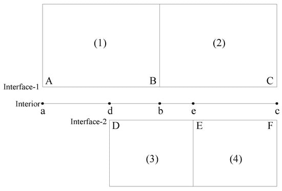
Figure 1.
Sliding mesh diagram.
2.2. Computational Configuration and Grids
The Air Force Modified Basic Finner (AFF) body-fin configuration is a typical spin missile with many experimental results. The geometry of the AFF is shown in Figure 2. The missile diameter d = 0.04572 m was used as the standard diameter, and the missile was composed of a 2.5d arched head, a 7.5d cylindrical body, and four fins. In this paper, a single jet nozzle is used, which is located 3.0d from the nose of the missile. The nozzle exhaust plane was round with a diameter of 0.1d. The reference area is Sref = 0.001642 m2, the reference length is Lref = 0.4572 m, and the moment reference point is the vertex of the missile head. The origin of the coordinate system is the head point of the projectile. The forward direction of the head point along the body rotary axis to the bottom of the projectile is the X axis. The forward direction of the Y axis from the body rotary axis to the center of the nozzle circular section is the Y axis. The positive direction of the Z axis is determined by the right-hand rule. For the convenience of analysis, the coordinate system is fixed to the projectile and rotates with the projectile during rotation. The rotation direction of the missile is the forward-looking clockwise direction. The direction of the spin was clockwise when viewed from the missile head.

Figure 2.
This AFF body-fin configuration: (a) Geometric parameters; (b) 3D model.
Three-dimensional structured grids are used in the numerical calculation. Figure 3a shows the spatial distribution of the grids. The far-field was located 20 times the missile diameter (20d) ahead of the missile nose since the external flow was supersonic. The outlet boundary was located 15d behind the base. The circumferential boundary is 15d from the projectile surface. Figure 3a also shows that there is an interface between the missile surface and the outer boundary. The area between the missile wall and the interface is the inner domain, and the area between the interface and the outer boundary is the outer domain. Figure 3b shows the wall grid distribution of the calculated shape and the local grid details near the nozzle. The lateral jet interference effect is closely related to the flow near the wall. Therefore, to ensure the accurate simulation of the boundary layer, the grid height of the first layer is determined according to the dimensionless wall distance , and the grid growth rate is 1.1.
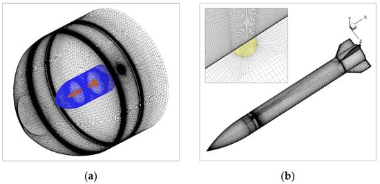
Figure 3.
Computational grids for AFF: (a) Computational domain; (b) surface grid of body-fin configuration.
The non-slip wall boundary condition is adopted on the surface of the projectile, and the outer boundary is set as the pressure far field. Since the computational flow conditions are supersonic, the bottom boundary of the computational grid is set as the pressure outlet, and the nozzle section is the pressure inlet. When the missile does not spin, the inner domain and the outer domain remain static; when the missile spins, sliding mesh technology is used. The inner domain grids spin with the missile, and the outer domain remains static to realize the numerical simulation of the flow field in the spinning state.
3. Validation of the Numerical Method
3.1. Validation of Jet Interaction Simulation
Figure 4 shows the model and grid diagram of cone-cylinder-flare (CCF). The CCF model is widely used in the verification of transverse jet simulations. The CCF was composed of a 2.8d conical nose, a 3.2d cylindrical body, and a 3d adjacent flared afterbody. A circular, sonic side jet nozzle 0.1d in diameter is located at x = 4.3d from the nose. The numerical simulation conditions are the same as the wind tunnel test conditions in reference [10]. The Mach number of the incoming flow is Ma = 3.0, the Reynolds number of the incoming flow is , the angles of attack are α = −10°, 0°, 10°, the jet pressure ratio is PR = 150, and the total jet temperature is = 280 K.
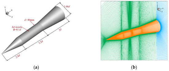
Figure 4.
Geometric parameters and grids of the CCF shape: (a) Geometric parameters and 3D model; (b) grids for computational.
Figure 5 shows the axial distribution of the surface pressure coefficient on the projectile obtained by numerical simulation under the conditions of Ma = 3.0, PR = 150, and the angles of attack α = 0°, 10°, and −10°. The experiments were carried out at the Trisonic Wind Tunnel (TMK) in Cologne. The TMK is a blow-down wind tunnel with a flexible nozzle and a cross-section of 0.6 m × 0.6 m [10]. The wind tunnel test data were obtained under the conditions of Ma = 3.0, Re = 1.9 × 10⁶, jet pressure ratio PR = 150, the total temperature of cross flow and side jet flow is T0 = 280 K, and jet gas is air. Figure 5 shows that the numerical simulation results are in good agreement with the wind tunnel test results at each angle of attack, and the values and positions of the high-pressure region in front of the nozzle and the low-pressure zone behind the nozzle are accurately simulated. There is a large difference between the calculated results and the experimental results near x/d = 6, and the calculated pressure value is too large. This may be because x/d = 6 is located at the transition between the cylinder and the skirt, where the interference of the shock wave and jet wake will occur. Given the good simulation results of the high-pressure region before the nozzle and the low-pressure region behind the nozzle and the lateral jet interference effect of the missile mainly reflected in the cylindrical section, it is considered that the numerical method can be used to study the lateral jet interference characteristics of the missile.

Figure 5.
Comparison of the pressure coefficient obtained by numerical simulations and experimental data for different angles of attack: (a) ; (b) ; (c) −10.
3.2. Validation of Spinning Missile Flowfield Simulation
The AFF missile model is widely used to study the Magnus effect. Therefore, the AFF is selected to verify the numerical method for spinning missile simulation. The verification shape is the original AFF configuration without a jet. The numerical simulation conditions are shown in Table 1.

Table 1.
Computational conditions for Magnus effect simulation.
Figure 6 shows the curves of the time-averaged lateral force coefficient and yaw moment coefficient of the AFF with different angles of attack in a spin period. The numerical results are compared with the wind tunnel test data [27]. The lateral force and yaw moment coefficient variations with the angles of attack agree well with the experimental results. The method employed to solve unsteady flow fields for the spinning missile is reliable and can be used for jet interference calculations of spinning missiles.
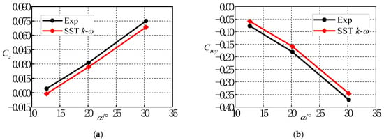
Figure 6.
Variation of the time-average aerodynamic coefficients with the angles of attack: (a) Lateral force coefficient; (b) Yawing moment coefficient.
3.3. Grid and Time Step Independence Verification
A grid independence study was carried out for the AFF with the jet model used in this paper. Three sets of meshes were examined, and the mesh details can be seen in Table 2. The calculation conditions were Ma = 2.5, = 101,325 Pa, , PR = 100, = 1 and = 300 K. Table 3 shows the relative errors between the normal force coefficient and the pitching moment coefficient calculated by using three sets of grids under the above conditions. Table 3 shows that the relative errors of the aerodynamic coefficients calculated by the three sets of grids are all kept within 2.5%. Among them, the relative errors of the pitching moment coefficients calculated by MeshA and MeshC are the largest, reaching −2.42%. The aerodynamic coefficients calculated by MeshB and MeshC are all kept within 1.5%, and it can be considered that the grid amount has little influence on the calculation results at this time. Considering the simulation accuracy and computational efficiency, MeshB is selected for subsequent calculations.

Table 2.
Computational grid parameters.

Table 3.
Aerodynamic coefficients and relative differences.
For the AFF body-fin configuration shown in Figure 2, MeshB is used to numerically simulate the unsteady flow field during the jet start-up process under the conditions of Ma = 2.5, = 101,325 Pa, , PR = 100, = 1 and = 300 K. In the unsteady calculation, the time steps are chosen as , , , and . Figure 7 shows the variation of the normal force coefficient CN obtained by different time steps with time after the start of the jet under the above calculation conditions. Figure 7 shows that and are quite different from other time steps. The curves of , and basically coincide before t = 0.4 ms, and there are some deviations after t = 0.4 ms. The curves of and coincide at all times, indicating that the calculation results do not change with the size of the time step when the time step is selected as and the smaller the time step is. Considering the calculation accuracy and efficiency, the time step used in the numerical calculation in this paper is . After the jet starts, the first step is the most difficult to perform due to the change in boundary conditions. So, in the first step, we took the CFL number to 0.1 and performed 400 steps of inner iteration. In the second step, the CFL was taken to 1 and 200 iterative steps were performed. In the third step, the number of internal iterations is taken to be 5 and 100 internal iterations are performed. In the fourth step, the CFL number was 10 and after the fifth step the CFD number was taken to be 15 and the inner iteration was 60 steps.
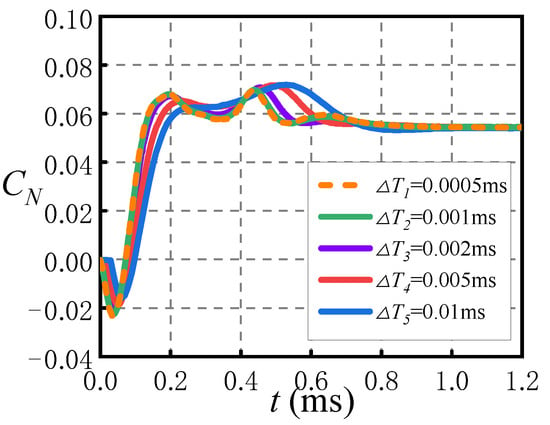
Figure 7.
The variation of normal force coefficient calculated by different time steps. (Ma = 2.5, , PR = 100).
4. Results and Discussion
4.1. Unsteady Characteristics of Non-Spinning Missile after the Lateral Jet Starts
4.1.1. Variation of Aerodynamic Characteristics with Time after Jet Start
Figure 7 shows the curves of the missile interference normal force coefficient and the interference pitching moment coefficient vary with time obtained by numerical simulation under the conditions of Ma = 2.5, α = 0°, and PR = 100. The moment reference point is the vertex of the head. The jet interference normal force coefficient and the jet interference pitching moment coefficient are obtained from the following:
Figure 8 shows that the magnitude of jet interference force increases rapidly to the extremal value in a short time, and then changes slowly until it reaches stability. For the missile and calculation conditions studied in this paper, the magnitude of jet interference force rapidly increases to the extremal value after 0.2 ms of jet start and reaches stability after about 1 ms of jet start. After the start of the lateral jet, the interference normal force coefficient generated on the missile first increases negatively with time, and there is a maximum value at approximately t = 0.05 ms. Then, the interference normal force coefficient increases rapidly and starts to oscillate and reaches stability at approximately t = 1 ms. The interference pitching moment coefficient on the missile first decreases negatively and then increases positively rapidly in the time range of t = 0~0.2 ms, reaching the maximum value at t = 0.45 ms. reaches stability at approximately t = 1 ms. Before t = 0.2 ms, the change in aerodynamic characteristics is most obvious. The extremal value of jet interference force and interference pitching moment in the process of the lateral jet start-up is not significantly different from the stable value.

Figure 8.
Variation of aerodynamic coefficient with time since lateral jet startup: (a) Interference normal force coefficient; (b) interference pitching moment coefficient; (c) of different components.
Figure 8c shows the variation of interference normal force coefficients of different components with time. When t = 0~0.2 ms, the variation of on the missile body with time is the same as that of the whole missile in Figure 8a. The of the fins is zero before t = 0.2 ms, indicating that the jet wake has not yet affected the fins. The of fins starts to increase in the range of t = 0.2~0.45 ms and reaches a maximum value around t = 0.45 ms. After that, began to decrease and reached stability before the missile body at approximately t = 0.8 ms. It takes a certain time for the jet to move with the freestream from the nozzle to the fins region. The transient effect of the jet interference on the fins lags behind that on the missile body. The peak on the fins at t = 0.45 ms is the reason why the normal force coefficient of the whole missile in Figure 8a decreases first, then increases and then decreases within t = 0.2~0.6 ms.
From the analysis above, it can be seen that after the jet starts, the direction of the jet interference normal force generated on the missile body is first the same as the direction of jet thrust; then, there is a reversal of direction, and the direction of the jet interference normal force is opposite to the jet thrust. The direction of the jet interference normal force on the fins is always opposite to the direction of jet thrust. Compared with the missile body, the jet interference characteristics on the fins have a delay effect. The interference normal force coefficient on the fins changes later, and the time to achieve stability is shorter than that of the missile body.
4.1.2. The Development of the Lateral Jet Interference Flow Field after Jet Startup
Figure 9 shows the pressure coefficient contours on the missile surface and symmetrical plane at different times since lateral jet startup under the conditions of Ma = 2.5, α = 0°, and PR = 100. Figure 9 shows that the distribution of the shock wave and pressure coefficient in the jet interference flow field changes with time after the start of the lateral jet. When t = 0.05 ms, the interference flow field structure is not obvious, but a bow shock wave is generated upstream of the nozzle, and a low-pressure area is generated downstream of the nozzle. When t = 0.1 ms, the height of the bow shock wave is increased compared with the previous time. The upstream of the nozzle has a blocking effect on the incoming flow, forming a high-pressure area. The obvious high-pressure area can be seen on the surface of the projectile, and the pressure change caused by the interference of the jet can be seen on the side of the projectile. The range of the low-pressure region downstream of the nozzle is also obviously increased. When t = 0.2 ms, the height and intensity of the bow shock wave further increase, and the range of the low-pressure region also increases. The jet wake has not reached the fins region at this moment. When t = 0.5 ms, the height and the range of the bow shock wave are still increasing, and the range of the high-pressure area upstream of the nozzle and on both sides of the surface of the missile body is further increased. Figure 9d also shows that the jet interference has affected the bottom of the missile body on the opposite side of the nozzle, and the jet wake has also been transported to the fins region. The jet wake interferes with the fin, and a low-pressure area can be clearly seen above the upper fin. By comparing Figure 8e with Figure 9f, it can be found that when t = 1 ms and t = 2.4 ms, the flow field on the missile surface and in the longitudinal symmetric plane basically no longer changes, the size of the separation zone caused by the interference of the jet and incoming flow no longer changes, and the flow field structure has basically reached stability.
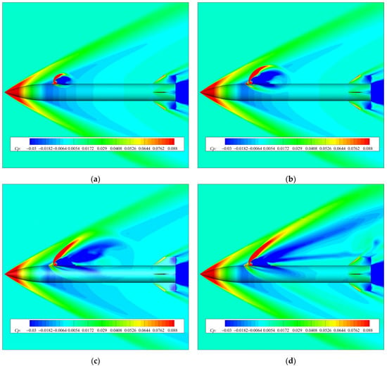
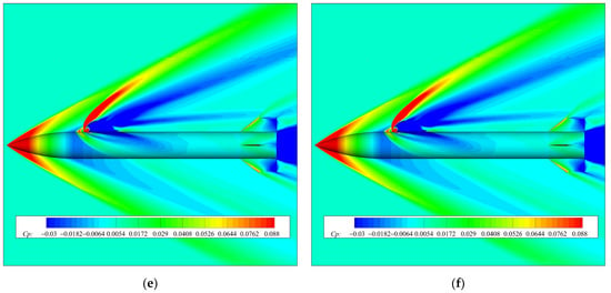
Figure 9.
Pressure coefficient contours on the missile surface and longitudinal symmetric plane at different times since lateral jet startup: (a) t = 0.05 ms; (b) t = 0.1 ms; (c) t = 0.2 ms; (d) t = 0.5 ms; (e) t = 1 ms; (f) t = 2.4 ms.
Figure 10 shows the pressure distribution along the axial direction of the upstream and downstream nozzle at θ = 0°. Compared with the high-pressure region in front of nozzle, the axial influence range of the downstream low-pressure region is larger. At t = 0.05 ms, the range of jet interference effect on the upstream of the nozzle is small, but the pressure coefficient increases greatly. With the increase in the jet start-up time, the high-pressure region moves towards the missile head. The influence range in the axial direction increases and the peak pressure decreases gradually. When the jet starts t = 0.2 ms, it can be seen that the pressure distribution upstream of the nozzle does not change significantly, and the pressure coefficient curve at each time is coincident, indicating that the transient jet interference effect on the upstream high-pressure region is completed within 0.2 ms.
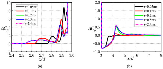
Figure 10.
Variations of jet interference force deflection angle, jet thrust angle and jet control force angle with time since lateral jet startup: (a) Deflection angle of the jet interference force; (b) and .
It can be seen from Figure 10b that the axial influence range of the low-pressure zone downstream of the nozzle is larger than that of the high-pressure zone upstream of the nozzle. At different moments, the minimum pressure coefficient in the low-pressure region downstream of the nozzle remains unchanged. When t = 0.05 ms, the influence range of jet interference is limited, and only the low-pressure region is formed by the interference in the range of 3 < x/d < 4. When t = 0.1 ms, there is a large increase in the low-pressure region behind the nozzle, and there is a local high pressure caused by the reattached shock wave. When t = 0.2 ms, the reattached high pressure behind the jet reaches the maximum peak, and the range of reattached high-pressure area is also larger than that when t = 0.1 ms. The pressure distribution hardly changes after t = 0.5 ms.
The duration time of the unsteady effect caused by the low-pressure zone behind the nozzle is longer than that caused by the high-pressure zone ahead of the nozzle. The duration time of the transient aerodynamic interference effect on the missile body during the start-up process of the lateral jet control is mainly affected by the low-pressure region. The high-pressure region in front of the nozzle appears rapidly since the lateral jet start(t = 0.05 ms). The axial range of the high-pressure region is smaller than the low-pressure region, but the pressure coefficient increases obviously, inducing the interference of normal force in the −y direction. Then, the range of the low-pressure area increases rapidly and the interference normal force in the +y direction induced by the low-pressure region has a major impact on the change of the normal force of the whole missile, resulting in the interference normal force coefficient in Figure 8 increases first and then decreases in the −y direction at t = 0–0.2 ms, and then increases rapidly in the +y direction.
4.2. Unsteady Characteristics of Spinning Missile after Lateral Jet Starting
In this section, the transient effect of spinning missiles with lateral jet control during jet startup and the variation characteristics of the missile aerodynamic parameters with time are investigated.
4.2.1. Transient Effect on Aerodynamic Characteristics in Spinning State
When the pulse jet control engine operating time and missile spin rate are certain, the angle of rotation of the projectile during the work of the pulse jet engine is determined. In this section, the numerical calculation conditions are Ma = 2.5, α = 0°, PR = 100, = 0.01, and the pulse jet control engine operating time is 3 ms, corresponding to a missile rotation angle of 63.91°. At zero angle of attack, the process of the pulse jet starting to the end of work is the same at any rolling angle. Therefore, choosing the jet engine starts when the missile rolling angle is φ = 0° and the jet engine stops working when the missile rolling angle is φ = 63.91°.
Figure 11 gives a schematic diagram of the synthesis of the jet interference force, jet control force and the definition of their deflection angles in this section. To facilitate the analysis, in the process of rotational motion, the coordinate system is solidly connected to the projectile. The origin of the coordinate system is defined as the apex of the projectile head, from the apex of the head along the axis of rotation of the projectile body pointing to the bottom of the projectile for the positive direction of the X axis. The longitudinal section of the nozzle is located in the XOY′ plane, from the axis of rotation of the projectile body pointing to the center of the circular section of the nozzle for the direction of the Y′ axis positive direction. The positive direction of the Z′ axis is determined by the right-hand rule.
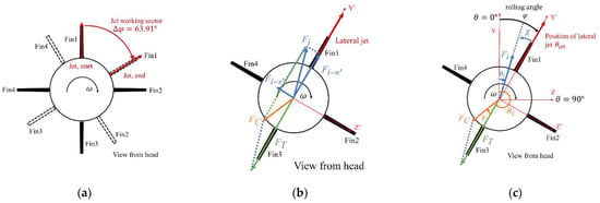
Figure 11.
Schematic diagram of the jet interference force, jet control force and deflection angle: (a) Schematic diagram of the jet working sector; (b) jet interference force Fi and jet control force FC during rotation; (c) deflection angle of Fi and FC.
The circumferential angle of the jet and Fin1 is θ = 0° at the initial moment, and the circumferential angle increases clockwise when looking backward from the head. Figure 11b,c give schematic diagrams of the synthesis of the thrust generated by the jet and the disturbance force caused by the jet interaction during the lateral jet control of the spinning missile and the definition of the direction, respectively. At any moment when the nozzle rotates at a certain angle, Fi in Figure 11b is the jet interference force, which can be decomposed into the normal force Fi-n′ and the lateral force Fi-z′. FT is the jet thrust generated by the jet, and FC is the resultant force of the reverse thrust and the jet interference force, namely, the actual jet control force acting on the missile during jet control. The circumferential angle at the nozzle is θjet, the direction of the jet interference force Fi is θi, the direction of the jet reverse thrust FT is θT, and the direction of the jet control force is θC. Define χ as the angle between the jet interference force and nozzle and γ as the angle between the jet control force and jet thrust:
Figure 12 shows the variation of jet interference force coefficients on the body and fins with time when Ma = 2.5, , PR = 100 and = 0.01. Figure 12 shows that the coefficient of the jet interference force on the body is greater than that on the fins. The coefficient of the jet interference force on the body changes immediately after the start of the jet. The coefficient of the jet interference force on the body reaches its extreme value at approximately t = 0.25 ms, when the coefficient of the jet interference force on the fins just begins to change. The difference between the jet interference force coefficient on the body after t = 1 ms and the jet interference force coefficient when the jet reaches a steady state is not significant, and the two curves basically coincide after t = 2 ms. It takes a longer time for the coefficient of jet interference force on the fins to reach the steady-state value than on the body, and the coefficient on the fins basically reaches the steady-state after approximately t = 2.5 ms.
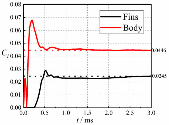
Figure 12.
Variation of jet interference force coefficient of different aerodynamic components with time since lateral jet startup.
Figure 13 gives the variation of the jet disturbance force deflection angle, the jet control force angle and the jet thrust angle with the jet start time under the conditions of Ma = 2.5, , PR = 100, and = 0.01. Figure 13a shows that the magnitude of the missile jet interference force deflection angle χ is large and varies very drastically within t = 0.1 ms after jet startup. Between t = 0.1 ms~0.3 ms, χ is basically zero and does not change much; after t = 0.3 ms, it starts to increase negatively, and after t = 0.5 ms, the change is no longer obvious, and the jet interference force deflection angle χ basically remains at a certain angle. In Figure 13b, the directions of the jet thrust and jet control force are basically the same within t = 0.1 ms. Before t = 0.3 ms, the difference between the jet control force angle and the jet thrust angle is small, and the curves basically coincide. After t = 0.3 ms, the jet control force angle increases, and after t = 1 ms, the two curves are basically parallel.
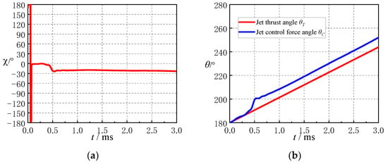
Figure 13.
Variations of jet interference force deflection angle, jet thrust angle and jet control force angle with time since lateral jet startup: (a) Deflection angle of the jet interference force; (b) and .
Figure 14 gives the variation curves of the rolling moment coefficients Cmx of different components with the jet start time after the rotating missile jet starts under the conditions of Ma = 2.5, α = 0, PR = 100, and = 0.01. Figure 14 shows that after jet startup, the rolling moment coefficient Cmx of the whole missile does not change with time at t = 0~0.3 ms. After t= 0.3 ms, the value of Cmx began to increase negatively rapidly, reached the maximum at t = 0.5 ms and then reduced the oscillation to maintain a certain range of values. The Cmx produced by the jet interference effect on the missile body is almost zero, and the Cmx of the fins is the main source of the full missile Cmx. After t = 0.3 ms, the Cmx of each fin is different. The Cmx of Fin4 decreases, and the Cmx of Fin1 and Fin2 increases. The jet interference effect on Fin3 is the smallest, and the Cmx of Fin3 almost does not change. The jet interference effect on Fin1 is the most obvious, and Cmx increases significantly, which is the main reason for the change of Cmx of the whole missile. When the rolling damping is constant, the increase in Cmx may cause a decrease in missile spin rate.
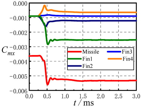
Figure 14.
Variation of rolling moment coefficient of different aerodynamic components with time since lateral jet startup.
The variation curves of the normal force coefficient CN’ and lateral force coefficient CZ’ with jet start-up time for different components under Ma = 2.5, , PR = 100, and = 0.01 are given in Figure 15. The unsteady pulse jet interference flow field at an angle of attack of zero will eventually form a quasi-steady jet interference flow field, and the duration of the transient jet interference characteristics on different components at zero angle of attack can be analyzed from Figure 15. Figure 15a shows that before t = 0.3 ms, the CN′ curve of the whole missile and the CN′ curve of the body basically coincide, and the normal force of the jet interference on the body is the main source of the normal force of the missile; The changes of Fin1 and Fin 3 are not obvious, and Fin 2 and Fin 4 contribute to the increase in interference normal force.
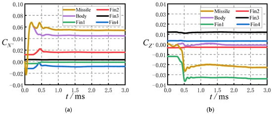
Figure 15.
Variation of aerodynamic coefficients of different aerodynamic components with time since lateral jet startup: (a) Normal force coefficient; (b) lateral force coefficient.
Figure 15b shows that the lateral force coefficient CZ′ of the whole missile is the same as that of the body before t = 0.3 ms, and there is no additional lateral force caused by jet interference on the fins. The jet interference lateral force rapidly increases to the extremal value at about 0.5 ms after the jet start, and the extremal value is not significantly different from the stable value. The change of lateral force coefficient on the missile body is not obvious, and the change of the lateral force of Fin1 leads to a change in the lateral force of the whole missile. When the jet wake reaches the fins region, a huge lateral force will be generated in a short period of time. In the design of the lateral jet control system of spinning missiles, it is necessary to pay attention to the influence of the aerodynamic characteristics change on the missile stability during this period. Compared with the body, the duration of the unsteady jet interference effect on the fins is longer. Therefore, the duration of the unsteady interference effect on the fins determines the duration of the unsteady interference effect of the whole missile.
Figure 16 gives the variation of the aerodynamic force coefficients of different components with time during the initiation of pulse jet control under the conditions of Ma = 2.5, , and PR = 100 with and without rotation. Figure 16 shows that the curves of the normal force coefficient on the missile body under the rotating and non-rotating conditions are basically coincident within t = 0~0.2 ms, and there is a certain difference in t = 0.2~0.6 ms, but the difference in the normal force coefficient is small, and it is coincident again after t = 0.6 ms. The time when the normal force coefficient on the fins begins to change is the same, and there is a certain difference within t = 0.4~0.8 ms. After t = 0.8 ms, the curves basically coincide, indicating that the influence of rotation on the normal force is not obvious.
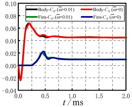
Figure 16.
Comparison of aerodynamic coefficients in spinning and non-spinning conditions.
From the analysis above, the jet interference force on the missile body changes immediately after the jet start of the spinning missile. The jet interference effect on the fins is delayed compared with that on the missile body. After approximately t = 0.3 ms, the jet interference force appears on the fins. The magnitude of the jet interference force on the body is larger than that on the fins, and the duration of the unsteady effect of the jet interference on the body is shorter than that on the fins. Before t = 0.3 ms, the angle of the jet control force is basically consistent with the direction of the jet thrust. The deflection angle of the jet control force increases rapidly compared with the jet thrust within t = 0.3~0.6 ms. After t = 0.6 ms, the deflection angle of the jet control force almost does not change. Among the four fins, the jet wake interference effect on Fin1 is the most obvious.
4.2.2. Transient Effect on Jet Interference Flow Field Characteristics in Spinning State
The reason for the change of aerodynamic characteristics in the previous section can be explained by analyzing the change of unsteady jet interference flow field with jet start-up time. Figure 17 gives the pressure coefficient contours on the surface of the spinning missile at different moments after the start of the lateral jet under the conditions of Ma = 2.5, , PR = 100 and = 0.01. For the convenience of comparison, the views at different moments are the top view directly above the nozzle. Figure 17 shows that a crescent-shaped high-pressure region is formed upstream of the nozzle after the lateral jet is started. With the increase in jet startup time, the shape of the high-pressure region upstream of the nozzle becomes two crescent-shaped and the influence range increases. The high-pressure region near the warhead is slightly larger than that near the nozzle. The low-pressure region downstream of the nozzle increases gradually with the start-up time, and the unsteady effect caused by the high-pressure region upstream of the nozzle has a shorter duration than the unsteady effect caused by the low-pressure region downstream of the nozzle.
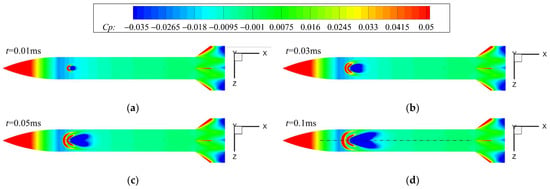
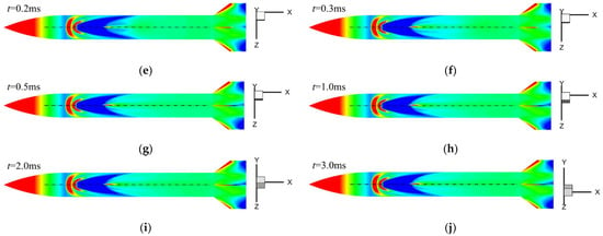
Figure 17.
Pressure coefficient contours of the missile surface at different times since lateral jet startup: (a) t = 0.01 ms, ϕ = 0.21°; (b) t = 0.03 ms, ϕ = 0.63°; (c) t = 0.05 ms, ϕ = 1.06°; (d) t = 0.1 ms, ϕ = 2.13°; (e) t = 0.2 ms, ϕ =4.26°; (f) t = 0.3 ms, ϕ = 6.39°; (g) t = 0.5 ms, ϕ = 10.65°; (h) t = 1.0 ms, ϕ = 21.31°; (i) t = 2.0 ms, ϕ = 42.61°; (j) t = 3.0 ms, ϕ = 63.91°.
As seen in Figure 17a–d, there are two crescent-shaped high-pressure regions upstream of the nozzle. With the increase in the jet start-up time, the shape of the high-pressure region has not changed, but the range is enlarged and closer to the missile head. The shape of the low-pressure region behind the nozzle changes from a water drop shape to a heart shape. The change in shape and area of the low-pressure region downstream of the nozzle during this period is more pronounced compared to the change in shape and area of the high-pressure region upstream of the nozzle.
Figure 17d–h shows that with the increase in the starting time of the jet, after t = 0.2 ms, the shape and influence area of the high-pressure upstream of the nozzle almost no longer change, and the distribution of the low-pressure region downstream of the nozzle still changes with time. When t = 0.2 ms, the range of the low-pressure region downstream of the nozzle is larger than that when t = 0.1 ms and t = 0.3 ms, indicating that the area of the low-pressure region behind the nozzle increases first and then decreases. At t = 0.2 ms, two low-pressure regions with slightly weaker intensity can be seen near the axis, and at t = 0.3 ms, the shape of these two slightly weaker low-pressure regions changes to a band shape, and the band-shaped low-pressure region located on the rotation side is larger than the band-shaped low-pressure region on the opposite side of the rotation in the axial direction. After t = 0.3 ms, the range of the two banded low-pressure regions begins to shrink gradually, and the asymmetry is more obvious. In addition, from Figure 17d–h, it can also be seen that when t = 0.1 ms, there is no local high-pressure region on the axis downstream of the nozzle. When t = 0.2 ms, the local high pressure appears on the axis behind the low-pressure region. When t = 0.3 ms, the range and intensity of the local high-pressure increase. With increasing time, it can be seen that the local high pressure deviates from the axis and deflects to the opposite side of the rotation direction. It can be seen that the low-pressure region behind the nozzle increases before t = 0.2 ms, which induces an increased jet interference force in the +y′ direction, resulting in an increase in CN′ in Figure 15a before 0.2 ms; After 0.2 ms, the reflected shock wave at the Mach disk acts on the surface of the missile body, resulting in the formation of local high pressure behind the nozzle. The local high pressure induces the jet interference in the −y′ direction. At the same time, the low-pressure area behind the nozzle decreases, and the jet interference force in the +y′ direction induced by the low-pressure area decreases, which jointly leads to the decrease in CN′ after t = 0.2 ms. When t = 0.2 ms, the CN′ on the surface of the missile body reaches the maximum value.
Figure 17 h–j shows that after the jet starts for 1 ms, the pressure coefficient distribution on the surface of the spinning missile body does not change, the unsteady jet interference effect is weakened, and a stable jet interference effect basically forms on the surface of the missile body.
Figure 18 gives the streamlines on the surface of the spinning missile at different moments after the start of the lateral jet under the conditions of Ma = 2.5, , PR = 100 and = 0.01. For the convenience of comparison, the views at different moments are the top view directly above the nozzle. Figure 18 shows that with the increase in the start time of the lateral jet, the range of the separation area on the missile body surface upstream of the nozzle caused by the jet interference effect gradually increases, the circumferential deflection angle of the two separation lines SL1 increases, and the reattachment point upstream of the nozzle gradually moves away from the nozzle. The range of the reattachment region downstream of the nozzle also increases with increasing jet start-up time. Before the jet interference flow field reaches stability, the streamlines show the same direction of deflection as the rotation direction. After reaching stability, the deflection of the upstream streamlines is more obvious than that of the downstream streamlines.
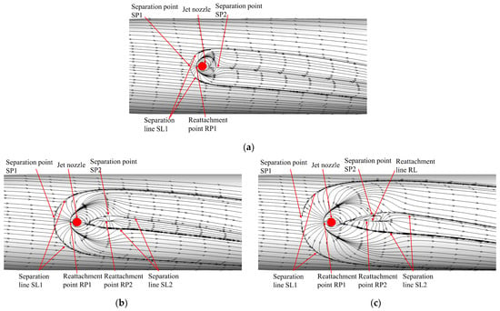
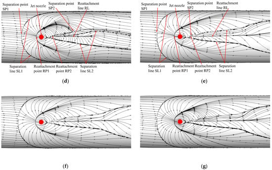
Figure 18.
Streamlines on the missile surface at different times since lateral jet startup: (a) t = 0.01 ms, ϕ = 0.21°; (b) t = 0.03 ms, ϕ = 0.63°; (c) t = 0.05 ms, ϕ = 1.06°; (d) t = 0.1 ms, ϕ = 2.13°; (e) t = 0.5 ms, ϕ =10.65°; (f) t = 1.0 ms, ϕ = 21.31°; (g) t = 3.0 ms, ϕ = 63.91°.
The flow direction near the wall is the same as the rotation direction of the missile due to the viscous effect. It can be seen from Figure 18a–c that the separation phenomenon in front of the nozzle appears earlier than the reattachment phenomenon behind the nozzle. In Figure 18a, the separation point SP1 and the reattachment point RP1 are very close, so there is a crescent-shaped high-pressure region in front of the nozzle in Figure 17a. With the increase in jet start-up time, the separation points SP1 and RP1 move to the missile head. The moving distance of SP1 is larger, and the distance between SP1 and RP1 increases, resulting in two high-pressure areas in front of the nozzle in Figure 17b,c, and the distance between the two high-pressure areas increases with the increase in jet start-up time.
From Figure 18b, it can be seen behind the nozzle that the reattachment line is not obvious, Figure 18c behind the nozzle can already see the obvious reattachment line. With the increase in the start time of the jet, the length of the reattachment line in Figure 18d is further increased. By comparing with Figure 17b–d, it can be seen that the appearance and development of the reattachment line behind the nozzle lead to the pressure change in the low-pressure area on the axis behind the nozzle, which leads to the change of the shape of the low-pressure area. By comparing Figure 18d,e, it can be seen that the change of the separation zone in front of the nozzle is not obvious, only the range increases, and the position of the separation point is closer to the missile head. However, the shape and range of the reattachment zone behind the nozzle have changed significantly, indicating that the unsteady jet interference effect during the start process of the jet has a longer duration of influence on the separation and reattachment phenomenon behind the nozzle than the influence of the separation zone in front of the nozzle.
Figure 18e–g shows that after t = 0.5 ms, the streamlines near the nozzle on the surface of the projectile do not change significantly. Thus, the change in the low-pressure region behind the nozzle in Figure 17g–j is also relatively insignificant, resulting in almost no change in CN′ on the missile body in Figure 16.
From the analysis above, it can be seen that when the missile spins, the streamlines near the wall deflect to the same side of the rotation direction, resulting in the separation area on the rotation direction side being larger than that on the other side. Within a short time after the start of the jet, separation point SP1, reattachment point RP1 and separation line SL2 will appear upstream of the nozzle, separation point SP2 will appear downstream of the nozzle, and there is no reattachment phenomenon. With increasing time, the separation point SP1 upstream of the nozzle is away from the nozzle. The circumferential deflection of the two separation lines SL1 is more obvious, and the range of the separation area expands. The reattachment point RP2 appears downstream of the nozzle, and the reattachment point RP2 is away from the nozzle first and then close to the nozzle, and the position is almost unchanged after t = 0.1 ms. The length of the reattachment line increased with increasing jet start time. Compared with the deflection of the separation line, the deflection of the reattachment line was not obvious. After t = 0.5 ms, the streamlines near the wall almost do not change.
Figure 19 gives the vorticity magnitude contours around the missile in different cross-sections along the axial direction of the missile at different times under the condition of Ma = 2.5, , PR = 100, and = 0.01. Figure 19 shows that the vortex is asymmetric about the longitudinal plane where the nozzle is located. The vortex deflects to the opposite side of the rotation direction, and the horseshoe vortex on the rotation direction side is slightly higher than that on the other side. In the section near the bottom of the projectile, it can be seen from the figure that the intensity of the vortex on the rotation direction side is greater than that of the other side vortex. Figure 19a shows that, unlike the pressure distribution on the surface of the projectile and the rapid change in near-wall flow in a short time after the jet starts, the vorticity change caused by the jet can only be seen in the two sections closest to the downstream of the nozzle at t = 0.1 ms. When t = 0.3 ms, the vorticity on both sides of the missile body increases in the section near the nozzle. From Figure 15, it can be found that the force on the fins begins to change at this time, indicating that although the jet vortex in the space has not reached the fins region, the change in vorticity developing downstream along the surface of the missile body as well as causing a change in pressure on the fins surface. It can be seen from Figure 19c,d that there are pairs of jet wake vortices in the fins region within t = 0.4~0.5 ms, indicating that the jet wake has reached the fins region at this period, and the vorticity in the cross section near the bottom of the projectile along the axial direction is still changing. It can be seen from Figure 19e,f that after t = 1 ms, the vorticity magnitude contours around the missile are almost no longer changed, and the jet wake continues to interfere with Fin1. Affected by the horseshoe vortex located on both sides of the missile body downstream, the vorticity at the root of the two horizontal fins increases significantly.
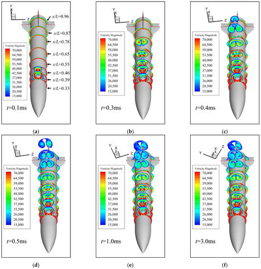
Figure 19.
Vorticity magnitude contours in different cross-sections at different times since lateral jet startup: (a) t = 0.1 ms, ϕ = 2.13°; (b) t = 0.3 ms, ϕ = 6.39°; (c) t = 0.4 ms, ϕ = 8.52°; (d) t = 0.5 ms, ϕ = 10.65°; (e) t = 1.0 ms, ϕ = 21.31°; (f) t = 3.0 ms, ϕ = 63.91°.
From the above analysis, it can be seen that when the spinning missile uses lateral jet control, the interference effect of the jet wake on Fin1 downstream of the nozzle is the strongest, resulting in an obvious lateral force on Fin1. The following will analyze the influence of unsteady jet interference on Fin1 force through the pressure distribution contours on both sides of the Fin1 surface. Figure 20 gives the pressure coefficient distribution contours of the two sides of Fin1 at different times under the conditions of Ma = 2.5, , PR = 100 and = 0.01. Because there is no cross flow at an angle of attack of zero, it is defined that the side of the rotating direction is the windward side of Fin1 and the other side is the leeward side. From Figure 20a–d, it can be seen that the fins region is not affected by the jet interference during a period after the start of the jet. When t = 0.1 ms and t = 0.2 ms, the pressure coefficient distribution on Fin1 is the same. When t = 0.3 ms, the high-pressure region of the front edge of the windward Fin1 surface increases, and the low-pressure range at the rear edge of Fin1 decreases. The increase in pressure on windward is more obvious, which induces the lateral force in the −z′ direction and causes the change of aerodynamic characteristics of the Fin1 in Figure 14 and Figure 15. From Figure 19b, it can be found that the jet wake vortex has not reached the fins region. After the lateral jet destroys the original flow field structure of the missile, the influence of flow field change has developed to the fins region, and the influence is mainly reflected in the fin1 root region. At t = 0.4 ms, compared with the moment of t = 0.3 ms, the pressure at the root of the front edge of the windward fin surface decreases, the high pressure at the front edge of the leeward fin surface decreases significantly, and the range of the low-pressure area at the trailing edge increases. It can be seen that the jet wake has developed to the fins region at this time in Figure 19c, and the jet wake has a strong interference effect on Fin1, resulting in a significant decrease in the pressure on the leeward side, and a further increase in the lateral force in the −z′ direction on Fin1. The interference of the jet wake on Fin1 leads to a faster increase in the lateral force of Fin1 near t = 0.4 ms in Figure 15. From Figure 20e–h, it can be seen that at t = 0.5 ms~2.0 ms, the high-pressure range at the front edge of two sides fin surface first increases and then decreases, and the low-pressure range at the trailing edge first decreases and then increases, resulting in the Fin1 in Figure 15 reaches the extremal value at t = 0.5 ms, and then decreases to a stable value. The change in the pressure coefficient at t = 2.0 ms~3.0 ms is no longer obvious.
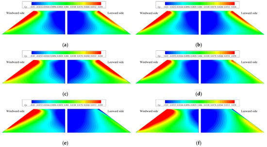

Figure 20.
Pressure coefficient contours on the windward and leeward surfaces of Fin1 at different times since lateral jet startup: (a) t = 0.1 ms; (b) t = 0.2 ms; (c) t = 0.3 ms; (d) t = 0.4 ms; (e) t = 0.5 ms; (f) t = 1.0 ms; (g) t = 2.0 ms; (h) t = 3.0 ms.
From the above analysis, it can be seen that after the start of the lateral control jet, although there is no obvious jet wake vortex in the space from the vorticity contours at t = 0.3 ms, the root of Fin1 is affected by jet interference. The pressure at the roots on both sides of the fin surface increases, and the range of the low-pressure region decreases. The jet interference effect increases the pressure of windward Fin1, and the pressure of the leeward side decreases. The direction of the additional interference force of Fin1 is from the windward side to the leeward side.
5. Conclusions
In this paper, the unsteady numerical method is used to simulate the unsteady lateral jet interference flow field in the process of jet starting when the missile is spinning or not. The variation of jet control characteristics and aerodynamic characteristics during the start-up process of the lateral jet under non-spinning and spinning conditions is studied. The results indicate the following:
(1) The aerodynamic characteristic of the missile caused by the jet interference effect has strong unsteady characteristics during the process of lateral jet start. The jet interference force will rapidly increase to the extremal value in a short period of time, and then slowly change until it is stable. For the missile and calculation conditions of this paper, the magnitude of jet interference force increases rapidly to the extreme value of about 0.2 ms since the jet start and becomes stable after about 1 ms from the jet start. The difference between the extremal value of jet interference force on the missile body and the stable value is more obvious than that on the fins. The normal force direction of the jet interference generated on the missile body is first the same as the direction of jet thrust and then is opposite to the jet thrust direction. The direction of the jet interference normal force of the fins is always opposite to the jet thrust direction. The interference normal force coefficient on the fins changes later, and the time to achieve stability is shorter than that of the missile body.
(2) The jet interference lateral force will appear in the start-up process of the lateral jet control of the spinning missile. When the jet wake develops to the fins region, it will have a strong interference effect on the fins, resulting in the rapid increase in the jet interference lateral force of the whole missile to the extremal value. The extremal value is not much different from the stable value, and the jet wake has the most obvious interference effect on the Fin1. The jet interference force on the missile body increases first and then decreases rapidly, and then increases in the opposite direction. The jet interference force on the missile body is larger than that on the fins, and the duration time of the transient effect of the jet interference on the missile body is shorter than that on the fins. The deflection angle of the jet interference force changes greatly with time since the jet start. However, because the magnitude of the jet interference force is small at this time, it has little effect on the jet control force. After a certain time, the angle between the jet control force and the azimuth of the nozzle does not change. Jet wake has the most obvious interference effect on Fin1. The deflection angle of jet control force reaches stability at t = 0.6 ms since the jet start.
(3) The time for the unsteady aerodynamic characteristics to reach stability during the initiation of the lateral jet of a spinning missile depends mainly on the duration time of the unsteady jet interference effect in the low-pressure region behind the nozzle. Separation points and separation zones appear immediately upstream of the nozzle after the jet start, and the streamlines on the missile body deflect in the same direction of spinning, and the moment of reattachment downstream of the nozzle appears later. When there is no obvious jet wake vortex in the fins region, the vortex on both sides of the missile body developing backward along the axial direction begins to affect the pressure distribution in the fins. The pressure at the root of Fin1 changes first, and then the pressure at the leading edge and trailing edge changes, resulting in the pressure on the rotation direction side of Fin1 increasing and the pressure on the leeward side of Fin1 decreasing. When the jet wake reaches the fins region, the lateral force of Fin1 will increase more rapidly.
Author Contributions
Conceptualization, Y.G. and J.L.; methodology, Y.G.; software, J.L.; validation, Y.G. and J.L.; formal analysis, Y.G.; investigation, Y.G.; resources, J.L.; data curation, J.L.; writing—original draft preparation, Y.G. and J.L.; writing—review and editing, Y.G. and J.L.; visualization, Y.G.; supervision, J.L.; project administration, J.L.; funding acquisition, J.L. All authors have read and agreed to the published version of the manuscript.
Funding
This research received no external funding.
Institutional Review Board Statement
Not applicable.
Informed Consent Statement
Not applicable.
Data Availability Statement
The data presented in this study are available on request from the corresponding author.
Conflicts of Interest
The authors declare no conflict of interest.
Nomenclature
| CN | normal force coefficient, normal force/qSref |
| Ci−n | jet interference normal force coefficient, jet interference normal force/qSref |
| CZ | lateral force coefficient, lateral force/qSref |
| Ci | jet interference force coefficient, jet interference force/qSref |
| Cmy | yawing moment coefficient, yawing moment/qLrefSref |
| Cmz | pitching moment coefficient, pitching moment/qLrefSref |
| Cp | pressure coefficient, |
| d | projectile diameter, 0.04572 m |
| E | total energy per unit mass, J/kg |
| h | height of the first layer grid, m |
| L | total length of missile, 0.4572 m |
| Lref | reference length, equal to projectile diameter, m |
| Ma | Mach number |
| jet Mach number | |
| p | static pressure, Pa |
| jet total pressure, Pa | |
| freestream static pressure, Pa | |
| q | dynamic pressure, |
| Reynolds number based on missile length, | |
| Sref | reference area, m2 |
| T | static temperature, K |
| freestream static temperature, K | |
| jet total temperature, K | |
| PR | jet pressure ratio, |
| force of jet thrust, N | |
| jet interference force, N | |
| u, v, w | velocity components in the x, y, and z directions, m/s |
| freestream velocity, m/s | |
| x | coordinate in the longitudinal direction, m |
| y+ | non-dimensional distance from wall to viscous sublayer |
| flight angle of attack, deg | |
| circumferential angle, deg | |
| kinematic viscosity, , m2/s | |
| rolling angle, deg | |
| χ | deflection angle of Fi, deg |
| γ | deflection angle of FC, deg |
| non-dimensional spin rate, |
References
- Raza, A.; Wang, H. Range and Accuracy Improvement of Artillery Rocket Using Fixed Canards Trajectory Correction Fuze. Aerospace 2022, 9, 32. [Google Scholar] [CrossRef]
- Gao, Y.; Lei, J.; Yin, J. Magnus Effect over Aerodynamic Components of Spinning Missile. Int. J. Aeronaut. Space Sci. 2022, 23, 447–460. [Google Scholar] [CrossRef]
- Zukoski, E.E.; Spaid, F.W. Secondary injection of gases into a supersonic flow. AIAA J. 1964, 2, 1689–1696. [Google Scholar] [CrossRef]
- Brandeis, J.; Gill, J. Experimental investigation of side-jet steering for supersonic and hypersonic missiles. J. Spacecr. Rocket. 1996, 33, 346–352. [Google Scholar] [CrossRef]
- Stahl, B.; Emunds, H.; Guelhan, A. Experimental investigation of hot and cold side jet interaction with a supersonic cross-flow. Aerosp. Sci. Technol. 2009, 13, 488–496. [Google Scholar] [CrossRef]
- Zapryagaev, V.; Kiselev, N.; Gubanov, D. Shock-Wave Structure of Supersonic Jet Flows. Aerospace 2018, 5, 60. [Google Scholar] [CrossRef] [Green Version]
- Brandeis, J.; Gill, J. Experimental investigation of super- and hypersonic jet interaction on missile configurations. J. Spacecr. Rocket. 1998, 35, 296–302. [Google Scholar] [CrossRef]
- Gnemmi, P.; Schäfer, H. Experimental and Numerical Investigations of a Transverse Jet Interaction on a Missile Body. In Proceedings of the 43rd AIAA Aerospace Sciences Meeting and Exhibit, Reno, NV, USA, 10–13 January 2005. [Google Scholar]
- Desikan, S.L.N.; Saravanan, R.; Suresh, K.; Tennyson, J.A.; Chandrasekar, N.; Subramanian, S.; Patil, M.M. Effect of Cold Jet Plume on Aerodynamics Coefficients. J. Spacecr. Rocket. 2015, 52, 404–416. [Google Scholar] [CrossRef]
- Stahl, B.; Esch, H.; Guelhan, A. Experimental investigation of side jet interaction with a supersonic cross flow. Aerosp. Sci. Technol. 2008, 12, 269–275. [Google Scholar] [CrossRef]
- Min, B.-Y.; Lee, J.-W.; Byun, Y.-H. Numerical investigation of the shock interaction effect on the lateral jet controlled missile. Aerosp. Sci. Technol. 2006, 10, 385–393. [Google Scholar] [CrossRef]
- Graham, M.J.; Weinacht, P.; Brandeis, J. Numerical investigation of supersonic jet interaction for finned bodies. J. Spacecr. Rocket. 2002, 39, 376–383. [Google Scholar] [CrossRef] [Green Version]
- Aswin, G.; Chakraborty, D. Numerical simulation of transverse side jet interaction with supersonic free stream. Aerosp. Sci. Technol. 2010, 14, 295–301. [Google Scholar] [CrossRef]
- Grandhi, R.K.; Roy, A. Effectiveness of a Reaction Control System Jet in a Supersonic Crossflow. J. Spacecr. Rocket. 2017, 54, 883–891. [Google Scholar] [CrossRef]
- Grandhi, R.K.; Roy, A. Performance of Control Jets on Curved Bodies in Supersonic Cross Flows. J. Spacecr. Rocket. 2019, 56, 1177–1188. [Google Scholar] [CrossRef]
- Chamberlain, R.; McClure, D.; Dang, A. CFD analysis of lateral jet interaction phenomena for the THAAD interceptor. In Proceedings of the 38th Aerospace Sciences Meeting and Exhibit, Reno, NV, USA, 10–13 January 2000. [Google Scholar]
- Takanashi, S.; Sentoh, E.; Yoshida, A.; Kikumoto, K.; Yamanaka, T.; Tanaka, H.; Hidaka, Y.; Sekino, N. Sidejet aerodynamics interaction effect of the missile. I—Estimation of missile sidejet interaction force by modeling in pressure field. In Proceedings of the 23rd Atmospheric Flight Mechanics Conference, Boston, MA, USA, 10–12 August 1998. [Google Scholar]
- Dash, S.; Perrell, E.; Arunajatesan, S.; Kannepalli, C. Lateral jet aerodynamic interaction simulations for dynamic pressure loads. In Proceedings of the 6th Aeroacoustics Conference and Exhibit, Lahaina, HI, USA, 12–14 June 2000. [Google Scholar]
- Ebrahimi, H.B. Numerical simulation of transient jet-interaction phenomenology in a supersonic freestream. J. Spacecr. Rocket. 2000, 37, 713–719. [Google Scholar] [CrossRef]
- Ebrahimi, H.B. Numerical Investigation of Jet Interaction in a Supersonic Freestream. J. Spacecr. Rocket. 2008, 45, 95–103. [Google Scholar] [CrossRef]
- Williams, N.J.; Moeller, T.M.; Thompson, R.J. Numerical simulations of high frequency transverse pulsed jet injection into a supersonic crossflow. Aerosp. Sci. Technol. 2020, 103, 105908. [Google Scholar] [CrossRef]
- McMaster, D.L.; Shang, J.S.; Golbitz, W.C. Supersonic, transverse jet from a rotating ogive cylinder in a hypersonic flow. J. Spacecr. Rocket. 1989, 26, 24–30. [Google Scholar] [CrossRef]
- DeSpirito, J. Transient Lateral Jet Interaction Effects on a Generic Fin-Stabilized Projectile. In Proceedings of the 30th AIAA Applied Aerodynamics Conference, New Orleans, LA, USA, 25–28 June 2012. [Google Scholar]
- DeRango, S.; Zingg, D.W. Improvements to a dual-time-stepping method for computing unsteady flows. AIAA J. 1997, 35, 1548–1550. [Google Scholar] [CrossRef]
- Pandya, S.; Venkateswaran, S.; Pulliam, T. Implementation of Preconditioned Dual-Time Procedures in OVERFLOW. In Proceedings of the 41st Aerospace Sciences Meeting and Exhibit, Reno, NV, USA, 6–9 January 2003. [Google Scholar]
- Menter, F.R. Two-equation eddy-viscosity turbulence models for engineering applications. AIAA J. 1994, 32, 1598–1605. [Google Scholar] [CrossRef] [Green Version]
- Jenke, L.M. Experimental Roll-Damping, Magnus, and Static-Stability Characteristics of Two Slender Missile Configurations at High Angles of Attack (0 to 90 deg) and Mach Numbers 0.2 through 2.5 [R]. USA: Arnold Engineering Development Center. 1976. Available online: https://archive.org/details/DTIC_ADA027027 (accessed on 6 November 2015).
Publisher’s Note: MDPI stays neutral with regard to jurisdictional claims in published maps and institutional affiliations. |
© 2022 by the authors. Licensee MDPI, Basel, Switzerland. This article is an open access article distributed under the terms and conditions of the Creative Commons Attribution (CC BY) license (https://creativecommons.org/licenses/by/4.0/).