
A Review of Spatial Robotic Arm Trajectory Planning

Abstract
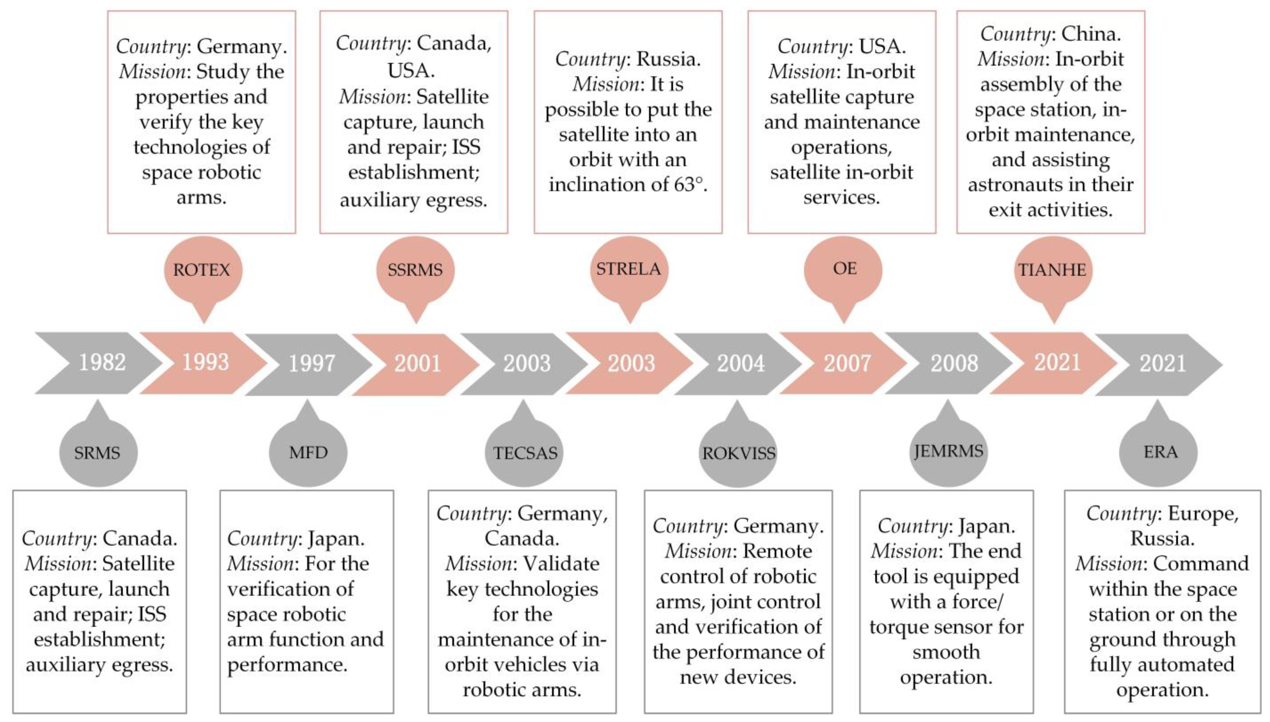
:1. Introduction
2. Spatial Robotic Arms Trajectory Planning Methods Based on Obstacle Avoidance Requirements
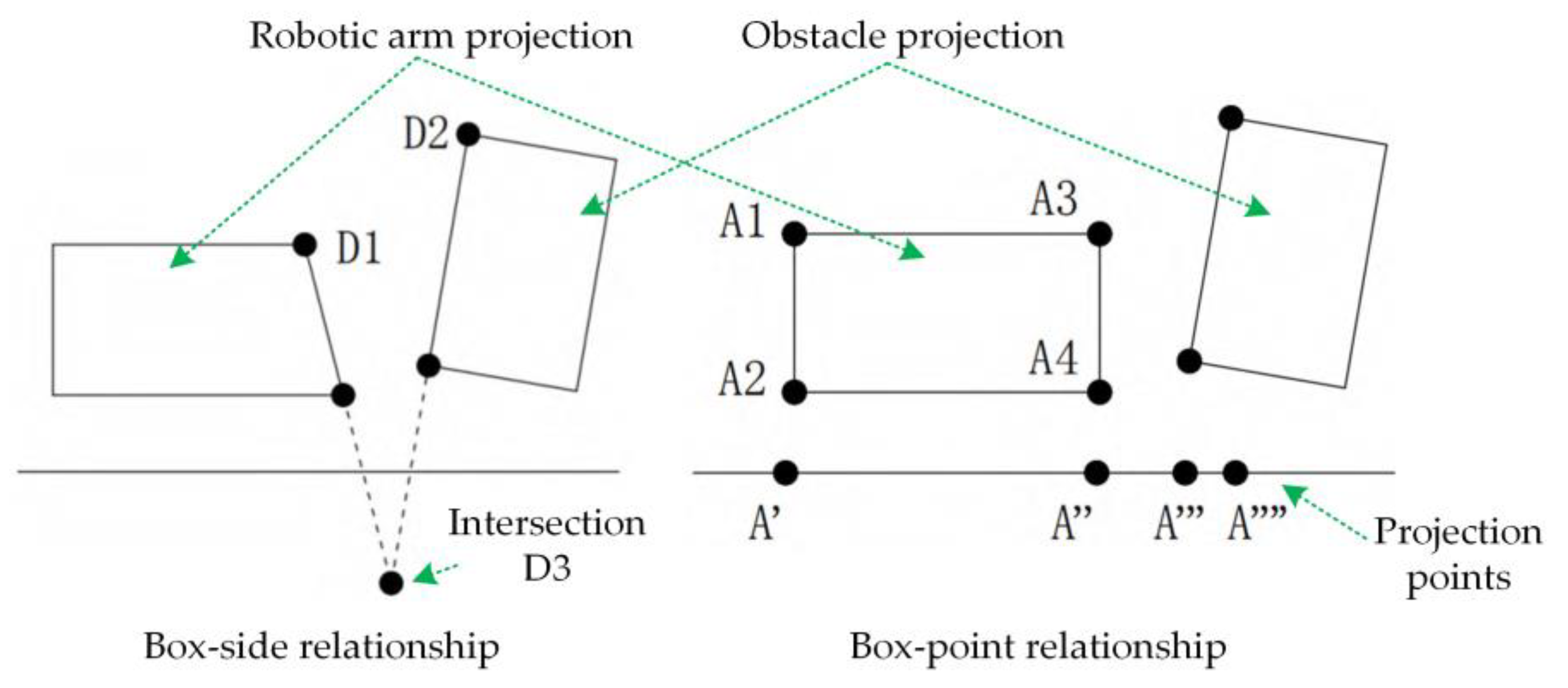
2.1. Spatial Obstacle Detection Methods
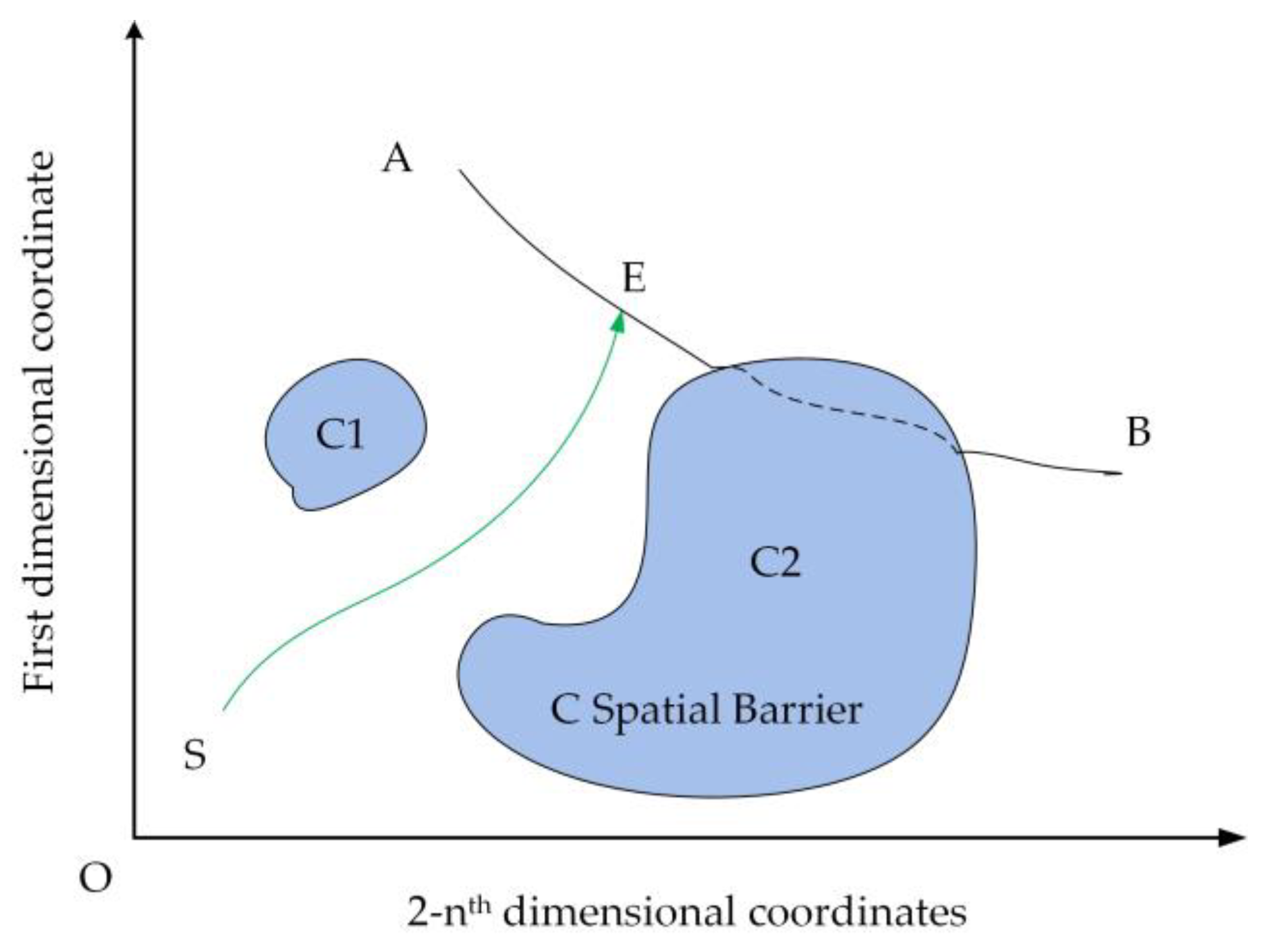
2.2. Spatial Robotic Arms Obstacle Avoidance Trajectory Planning Methods
3. Spatial Robotic Arms Trajectory Planning Methods Based on Motion Requirements
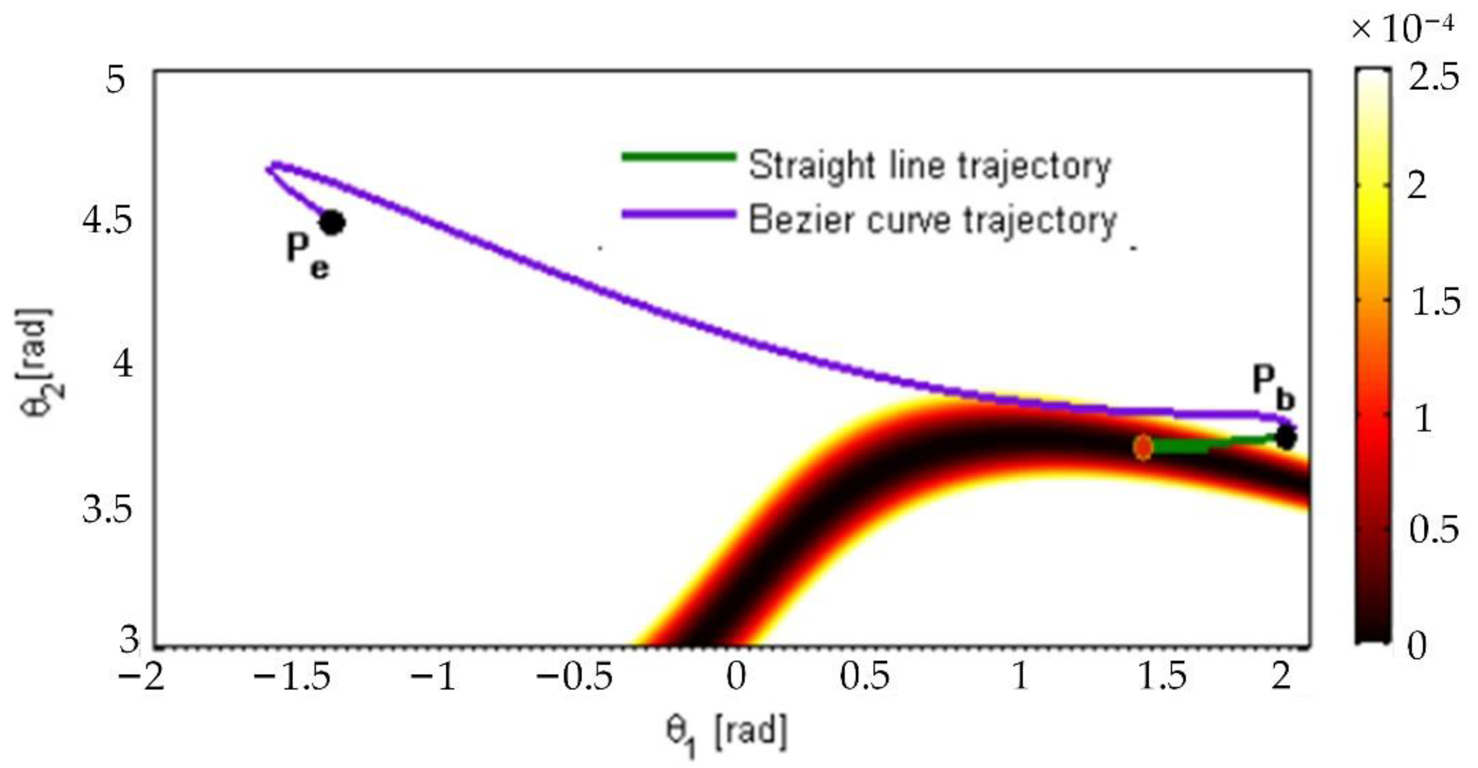
3.1. Research on Basic Spatial Trajectory Planning Methods
3.2. Research on Optimal Trajectory Optimization Methods
3.2.1. Genetic Algorithm
- (1)
- Randomize the initial population and set the main parameters such as variation probability, crossover probability, the maximum number of iterations, and the number of populations;
- (2)
- Selecting populations according to specific rules (e.g., roulette method) based on the fitness function;
- (3)
- Perform crossover variation operation on individuals of the population;
- (4)
- Discriminate whether the maximum number of iterations is reached or not. If the maximum number of iterations is reached, the algorithm ends, otherwise returns to step (2).
3.2.2. Particle Swarm Optimization Algorithm
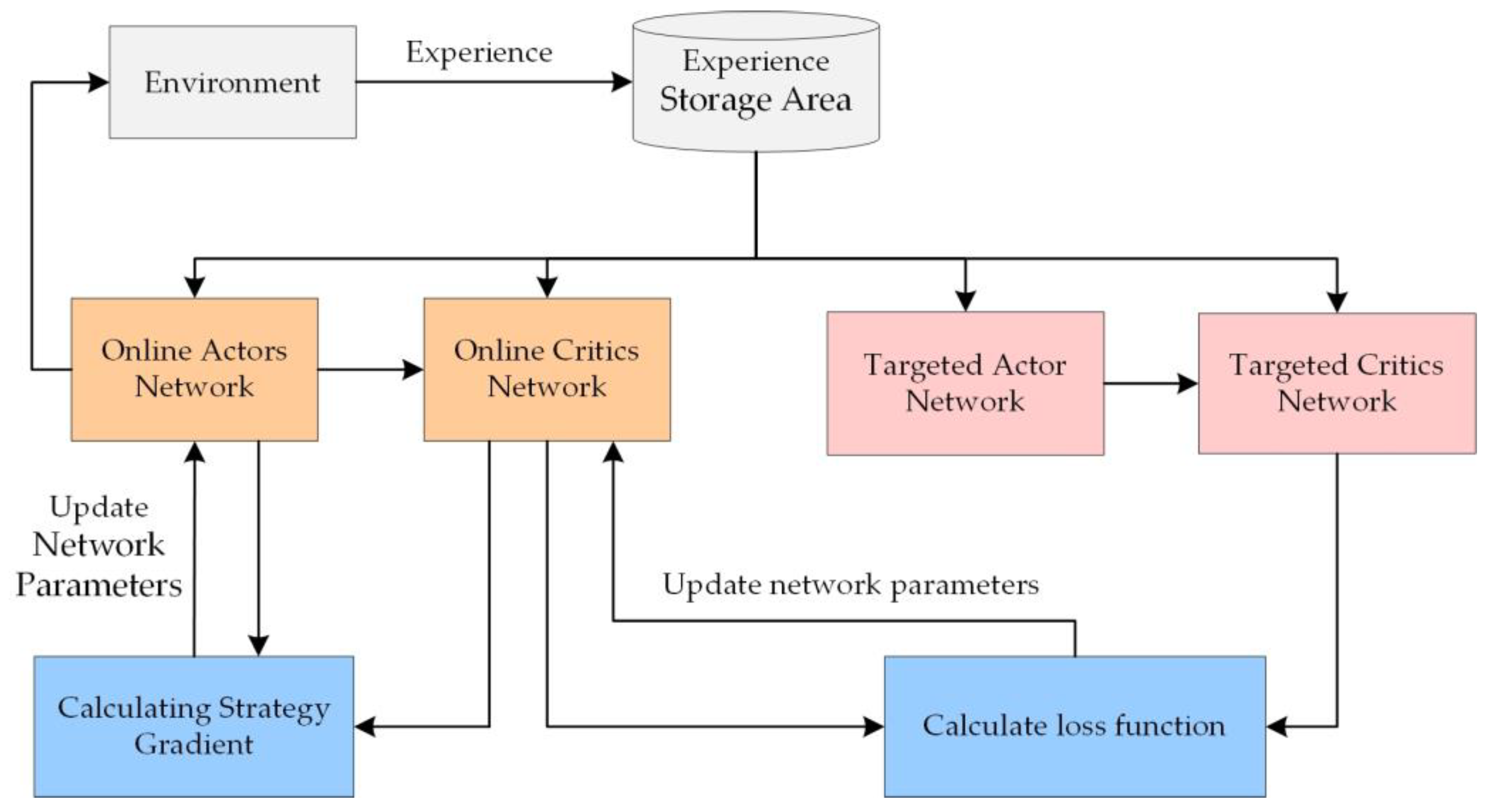
3.2.3. Application of Reinforcement Learning Algorithms
4. Summary and Outlook
Author Contributions
Funding
Institutional Review Board Statement
Informed Consent Statement
Data Availability Statement
Conflicts of Interest
References
- Flores-Abad, A.; Ma, O.; Pham, K.; Ulrich, S. A review of space robotics technologies for on-orbit servicing. Prog. Aerosp. Sci. 2014, 68, 1–26. [Google Scholar] [CrossRef] [Green Version]
- Zhu, R.Z.; Wang, H.F. Review of manned spacecraft operator systems (continued). Manned Spacefl. 2010, 16, 48–58. [Google Scholar] [CrossRef]
- Haidegger, T. Advanced Robotic Arms in Space. In Proceedings of the International Astronautical Federation—55th International Astronautical Congress, Vancouver, BC, Canada, 4–8 October 2004; Volume 4, pp. 2584–2593. [Google Scholar]
- Hirzinger, G.; Brunner, B.; Dietrich, J. ROTEX-The First Remotely Controlled Robot in Space. IEEE Trans. Robot. Autom. 1994, 6, 2604–2611. [Google Scholar]
- Preusche, C.; Reintsema, D.; Landzettel, K.; Hirzinger, G. Robotics Component Verification on ISS ROKVISS—Preliminary Results for Telepresence. Int. Conf. Intell. Robot. Syst. 2006, 9, 9–15. [Google Scholar]
- Martin, E.; Dupuis, E.; Piedboeuf, J.C.; Doyon, M. The TECSAS Mission From a Canadian Perspective. In Proceedings of the i-SAIRAS 2005, the 8th International Symposium on Artificial Intelligence, Robotics and Automation in Space, Munich, Germany, 5–8 September 2005; Volume 2, pp. 5–8. [Google Scholar]
- Wang, X.; Wang, W. An overview of key technology features of Tiangong space station. China Sci. Technol. Sci. 2021, 51, 1287–1298. [Google Scholar]
- Wang, M.Y.; Li, J. Research on trajectory planning algorithm for six-degree-of-freedom industrial robots. Precis. Manuf. Autom. 2017, 4, 47–49, 62. [Google Scholar] [CrossRef]
- Cao, Z.Y.; Wang, H.; Wu, W.R. Time-optimal and pulsation-optimal trajectory planning for slurry spraying manipulator. J. Cent. South Univ. 2013, 44, 114–121. [Google Scholar]
- Zhu, S.Q.; Liu, S.G.; Wang, X.Y. Time-optimal pulsating continuous trajectory planning algorithm for robots. J. Mech. Eng. 2010, 46, 47–52. [Google Scholar] [CrossRef]
- Oda, M.; Kibe, K.; Yamagata, F. ETS-VII, space robot in-orbit experiment satellite. IEEE 1996, 1, 739–744. [Google Scholar] [CrossRef]
- Zhai, Y.B. Research on Space Robotic Arm Trajectory Planning and Ground Simulation Method. Master’s Thesis, Harbin Institute of Technology, Harbin, China, 2013. [Google Scholar]
- Acquatella, P. Development of automation & robotics in space exploration. In Proceedings of the AIAA SPACE Conference & Exposition, Pasadena, CA, USA, 27–30 June 2006. [Google Scholar]
- Anderson, R.C.; Adamo, D.; Buczkowski, D.; Dohm, J.; Haidegger, T.; Jones, T.; Podnar, G.; Wyrick, D. Next frontier in planetary geological reconnaissance: Low-latency telepresence. Icarus 2021, 368, 114558. [Google Scholar] [CrossRef]
- Haidegger, T.; Benyo, Z. Surgical robotic support for long duration space missions. Acta Astronaut. 2008, 63, 996–1005. [Google Scholar] [CrossRef]
- Yoshida, K.; Hashizume, K.; Abiko, S. Zero reaction maneuver: Flight validation with ETS-VII space robot and extension to kinematically redundant arm. In Proceedings of the IEEE International Conference on Robotics & Automation, Seoul, Korea, 21–26 May 2001. [Google Scholar]
- Li, Q.Z.; Gu, W.K.; Ye, X.Q.; Xiang, Z.Y. Research on intelligent pre-scanning control method for path tracking of mobile robots. Robot 2002, 252–255. [Google Scholar] [CrossRef]
- Ferguson, D.; Kalra, N.; Stentz, A. Replanning with RRTs. In Proceedings of the IEEE International Conference on Robotics & Automation, Orlando, FL, USA, 15–19 May 2006. [Google Scholar]
- Yin, B. Research on Redundant Robotic Arm Kinematics and Obstacle Avoidance Path Planning. Master’s Thesis, Harbin Institute of Technology, Harbin, China, 2014. [Google Scholar]
- Luo, F. Fast Collision Detection and Intersection Calculation for 3D Mesh Models. Master’s Thesis, Zhejiang University, Zhejiang, China, 2005. [Google Scholar]
- Zeng, C. Research on Space Robotic Arm Motion and Mission Planning Methods for On-Orbit Services. Diploma Thesis, Dalian University of Technology, Dalian, China, 2013. [Google Scholar]
- Wang, Z.P. Research on Motion Planning of Robotic Arm in Constrained Space. Master’s Thesis, Beijing University of Posts and Telecommunications, Beijing, China, 2017. [Google Scholar]
- Jiang, G.Y. Research and Application of Collision Detection Algorithm Based on Wraparound Box. Master’s Thesis, University of Electronic Science and Technology, Chengdu, China, 2012. [Google Scholar]
- Bai, W.D.; Zhou, Z.P.; Zhang, S.B.; Wu, J.Y. A study on inter-object collision detection in VRML. Comput. Appl. Res. 2004, 6, 128–130+133. [Google Scholar]
- Menasri, R.; Nakib, A.; Daachi, B.; Oulhadj, H.; Siarry, P. A trajectory planning of redundant manipulators based on bilevel optimization. Appl. Math. Comput. 2015, 250, 934–947. [Google Scholar] [CrossRef]
- Hou, Z.C. Spatial Capture-Oriented Robot Path Planning and Controller Design. Master’s Thesis, Harbin Institute of Technology, Harbin, China, 2011. [Google Scholar]
- Zhu, Z.X.; Jing, S.; Zhong, J.F.; Wang, M.M. Spatially redundant robotic arm obstacle avoidance path planning based on collision detection. J. Northwestern Polytech. Univ. 2020, 38, 183–190. [Google Scholar] [CrossRef]
- Han, F.; Wang, Z.; He, L.; Wu, H.; Yang, G.; Duan, G. Trajectory plan for an ultra-short distance on-orbit service based on the Gaussian pseudo-spectral method. IEEE/CAA J. Autom. Sin. 2018, 1–9. [Google Scholar] [CrossRef]
- Li, Y.C.; Jiang, Q.; Wang, C.H. Adaptive trajectory planning of robotic arms in confined spaces. Electron. Compon. Inf. Technol. 2021, 5, 53–54. [Google Scholar] [CrossRef]
- Li, B.H.; Zhang, Y.P.; Wu, Z.Y.; Yu, D.S.; Yang, Y.Z.; Du, S.Y. Research and implementation of ROS-based SLAM for mobile robots. Electron. Compon. Inf. Technol. 2020, 4, 51–52. [Google Scholar] [CrossRef]
- Zhang, C.F.; Chen, M.H.; Hou, Y.Y.; Zhang, W.J. Redundant space robotic arm trial search obstacle avoidance strategy. Aerosp. Shanghai 2022, 39, 1–7. [Google Scholar] [CrossRef]
- Wang, Y.; Jia, Y.H.; Xu, S.J. Collision-free trajectory planning algorithm for redundant space robotic arm coarse capture segment. Chin. Space Sci. Technol. 2012, 32, 49–56. [Google Scholar]
- Zhuang, H.Z.; Du, S.X.; Wu, J. Research on robot path planning and related algorithms. Bull. Sci. Technol. 2004, 20, 6. [Google Scholar]
- Huang, Y.S.; Tian, D.; Li, H.J.; Jiao, R.H. A tumbling non-cooperative spacecraft approach and flight avoidance trajectory planning and tracking control method. Space Control Technol. Appl. 2021, 47, 8. [Google Scholar]
- Kang, G.H.; Zhang, H.; Wei, J.Y.; Wu, J.Q.; Zhang, L. Energy-optimal spacecraft continuous dynamic obstacle avoidance trajectory planning. J. Astronaut. 2021, 42, 305–313. [Google Scholar]
- Lozano-Perez, T. Spatial Planning: A Configuration Space Approach. IEEE Trans. Comput. 2006, C-32, 108–120. [Google Scholar] [CrossRef] [Green Version]
- Zhang, C.; Sun, H.; Jia, Q.; Lei, H. A Novel Division Based Self-Motion Algorithm for Avoiding Obstacles for Redundant Manipulators. In Proceedings of the IEEE International Conference on Automation & Logistics, Jinan, China, 18–21 August 2007. [Google Scholar]
- Beiner, L.; Mattila, J. An improved pseudoinverse solution for redundant hydraulic manipulators. Robotica 1999, 17, 173–179. [Google Scholar] [CrossRef]
- Jin, L.; Li, S.; La, H.M.; Luo, X. Manipulability Optimization of Redundant Manipulators Using Dynamic Neural Networks. IEEE Trans. Ind. Electron. 2017, 64, 4710–4720. [Google Scholar] [CrossRef]
- Pisculli, A.; Felicetti, L.; Gasbarri, P.; Palmerini, G.B.; Sabatini, M. A reaction-null/Jacobian transpose control strategy with gravity gradient compensation for on-orbit space manipulators. Aerosp. Sci. Technol. 2014, 38, 30–40. [Google Scholar] [CrossRef]
- Sabatini, M.; Gasbarri, P.; Palmerini, G.B. Coordinated control of a space manipulator tested by means of an air bearing free floating platform. Acta Astronaut. 2017, 139, 296–305. [Google Scholar] [CrossRef]
- Wang, Y.; Wang, L. Whole-body collision avoidance control design using quadratic programming with strict and soft task priorities. Robot. Comput. Integr. Manuf. 2020, 62, 101882. [Google Scholar] [CrossRef]
- Stolfi, A.; Gasbarri, P.; Sabatini, M. Spazio. Performance Analysis and Gains Tuning Procedure for a Controlled Space Manipulator Used for Non-Cooperative Target Capture Operations. Aerotec. Missili Spaz. 2018, 97, 3–12. [Google Scholar] [CrossRef]
- Tringali, A.; Cocuzza, S. Finite-Horizon Kinetic Energy Optimization of a Redundant Space Manipulator. Appl. Sci. 2021, 11, 2346. [Google Scholar] [CrossRef]
- Li, C.; Zheng, Z.X.; Yuan, J.P. A trajectory optimization method with frictional contacts for on-orbit capture. Acta Astronaut. 2020, 175, 90–98. [Google Scholar] [CrossRef]
- Lu, X.; Jia, Y. Trajectory Planning of Free-Floating Space Manipulators With Spacecraft Attitude Stabilization and Manipulability Optimization. IEEE Trans. Syst. Man Cybern. Syst. 2020, 51, 7346–7362. [Google Scholar] [CrossRef]
- Zhao, Z.Y.; Zhao, J.D.; Zhao, L.L.; Yang, X.H. A method for solving the inverse kinematics of SSRMS configuration space robotic arm. J. Mech. Eng. 2022, 58, 15. [Google Scholar]
- Kathib, O. Real-Time Obstacle Avoidance for Manipulators and Mobile Robots; Springer: New York, NY, USA, 1986. [Google Scholar]
- Zhan, B.; Jin, M.; Yang, G.; Zhang, C. A novel strategy for space manipulator detumbling a non-cooperative target with collision avoidance. Adv. Space Res. 2020, 66, 785–799. [Google Scholar] [CrossRef]
- Gao, X.; Wu, H.; Zhai, L.; Sun, H.; Jia, Q.; Wang, Y.; Wu, L. A rapidly exploring random tree optimization algorithm for space robotic manipulators guided by obstacle avoidance independent potential field. Int. J. Adv. Robot. Syst. 2018, 15. [Google Scholar] [CrossRef]
- Lozano-Perez, T. Automatic Planning of Manipulator Transfer Movements. IEEE Trans. Syst. Man Cybern. 1981, 11, 681–698. [Google Scholar] [CrossRef] [Green Version]
- Maciejewski, A.A.; Fox, J.J. Automation. Path planning and the topology of configuration space. IEEE Trans. Robot. Autom. 1993, 9, 444–456. [Google Scholar] [CrossRef]
- Kondo, K. Motion planning with six degrees of freedom by multistrategic bidirectional heuristic free-space enumeration. IEEE Trans. Robot. Autom. 1991, 7, 267–277. [Google Scholar] [CrossRef]
- Zhao, Z.M. Path planning for service-oriented robots based on weighted A* algorithm. J. Huazhong Univ. Sci. Technol. Nat. Sci. Ed. 2008, 3. [Google Scholar] [CrossRef]
- Chen, G.; Yuan, B.; Jia, Q.; Sun, H.; Guo, W. Failure tolerance strategy of space manipulator for large load carrying tasks. Acta Astronaut. 2018, 148, 186–204. [Google Scholar] [CrossRef]
- Guo, J.F.; Yu, X.Q.; Zheng, H.X.; Yan, P. Autonomous detection and fusion path planning for planetary vehicles. Unmanned Syst. Technol. 2020, 3, 17–23. [Google Scholar]
- Fox, D.; Burgard, W.; Thrun, S. The dynamic window approach to collision avoidance. IEEE Robot. Autom. Mag. 1997, 4, 23–33. [Google Scholar] [CrossRef] [Green Version]
- Valle, S.; Kuffner, J.J., Jr. Randomized kinodynamic planning. Int. J. Robot. Res. 2001, 15, 378–400. [Google Scholar]
- Rybus, T. Point-to-Point Motion Planning of a Free-Floating Space Manipulator Using the Rapidly-Exploring Random Trees (RRT) Method. Robotica 2019, 38, 957–982. [Google Scholar] [CrossRef]
- James, F.; Shah, S.V.; Singh, A.K.; Krishna, K.M.; Misra, A.K. Reactionless Maneuvering of a Space Robot in Precapture Phase. J. Guid. Control Dyn. 2016, 39, 2419–2425. [Google Scholar] [CrossRef]
- Guan, Y.Z.; Song, C.L. Path Planning of the Free-floating Manipulator for Capturing a Moving Target. Robot 2017, 39, 803–811. [Google Scholar]
- Yan, S. Development of Intelligent Analysis and Planning System for Space Robotic Arm Table-Taking Sampling Strategy. Master’s Thesis, Beijing University of Posts and Telecommunications, Beijing, China, 2020. [Google Scholar]
- Hoffmann, W.; Sauer, T. A spline optimization problem from robotics. Rend. Mat. Appl. 2006, 26, 221–230. [Google Scholar]
- Garrido, J.; Wen, Y.; Li, X. Robot trajectory generation using modified hidden Markov model and Lloyd’s algorithm in joint space. Eng. Appl. Artif. Intell. 2016, 53, 32–40. [Google Scholar] [CrossRef]
- Wen, Y.F.; Sun, L.N. Trajectory optimization algorithm for surface-modified redundant robot joint space. Mech. Sci. Technol. Aerosp. Eng. 2018, 37, 1870–1874. [Google Scholar]
- Valero, F.; Mata, V.; Besa, A. Trajectory planning in workspaces with obstacles taking into account the dynamic robot behaviour. Mech. Mach. Theory 2006, 41, 525–536. [Google Scholar] [CrossRef]
- Zhang, P.; Gong, J.; Ning, H.; Zeng, Y.; Liu, Y.; Wei, L. Study on Trajectory Combination and Connection Problems of Spray-painting Robot for Large Curvature Combination Surfaces. Adv. Eng. Sci. 2016, 48, 217–222. [Google Scholar] [CrossRef]
- Saramago, S.; Steffen, V.; Theory, M. Optimization of the Trajectory Planning of Robot Manipulators Taking into Account the Dynamics of the System. Mech. Mach. Theory 1998, 33, 883–894. [Google Scholar] [CrossRef]
- Tortopidis, I.; Papadopoulos, E. On point-to-point motion planning for underactuated space manipulator systems. Robot. Auton. Syst. 2007, 55, 122–131. [Google Scholar] [CrossRef]
- An, J.; Li, X.; Zhang, Z.; Man, W.; Zhang, G. Joint Trajectory Planning of Space Modular Reconfigurable Satellites Based on Kinematic Model. Int. J. Aerosp. Eng. 2020, 2020, 1–17. [Google Scholar] [CrossRef]
- Cui, H. Polynomial interpolation method for motion planning of free-floating space robots. J. Beijing Inf. Sci. Technol. Univ. 2019, 34, 8. [Google Scholar]
- Papadopoulos, E.; Tortopidis, I.; Nanos, K. Smooth Planning for Free-floating Space Robots Using Polynomials. In Proceedings of the IEEE International Conference on Robotics & Automation, Barcelona, Spain, 18–22 April 2006. [Google Scholar]
- Misra, G.; Bai, X. Dynamics. Optimal Path Planning for Free-Flying Space Manipulators via Sequential Convex Programming. J. Guid. Control Dyn. 2017, 40, 3019–3026. [Google Scholar] [CrossRef]
- Xin, P.; Rong, J.; Yang, Y.; Xiang, D.; Xiang, Y. Trajectory planning with residual vibration suppression for space manipulator based on particle swarm optimization algorithm. Adv. Mech. Eng. 2017, 9. [Google Scholar] [CrossRef] [Green Version]
- Li, M. Research on Spatial Robotic Arm Trajectory Planning. Master’s Thesis, Lanzhou Jiaotong University, Lanzhou, China, 2019. [Google Scholar]
- Dudek, G.; Jenkin, M.; Kambhampati, S.; Latombe, J.C. Robot Motion Planning; Kluwer Academic Publishers: Alphen aan den Rijn, The Netherlands, 1990. [Google Scholar]
- Li, L.F.; Ma, H. A Research on the Cubic Uniform B-spline Curve and Its Application on Trajectory Planning Algorithm of Industry Robot. Sci. Technol. Eng. 2013, 13, 3621–3625+3646. [Google Scholar]
- Meike, D.; Ribickis, L. Industrial robot path optimization approach with asynchronous fly-by in joint space. In Proceedings of the IEEE International Symposium on Industrial Electronics, Gdansk, Poland, 27–30 June 2011. [Google Scholar]
- Wang, M.; Luo, J.; Fang, J.; Yuan, J. Optimal trajectory planning of free-floating space manipulator using differential evolution algorithm. Adv. Space Res. 2018, 61, 1525–1536. [Google Scholar] [CrossRef]
- Nanos, K.; Papadopoulos, E. Systems, E. Avoiding dynamic singularities in Cartesian motions of free-floating manipulators. IEEE Trans. Aerosp. Electron. Syst. 2015, 51, 2305–2318. [Google Scholar] [CrossRef]
- Rybus, T.; Barcinski, T.; Lisowski, J.; Seweryn, K.; Nicolaukuklinski, J.; Grygorczuk, J.; Krzewski, M.; Skup, K.; Szewczyk, T.; Wawrzaszek, R. Experimental demonstration of singularity avoidance with trajectories based on the Bézier curves for free-floating manipulator. In Proceedings of the International Workshop on Robot Motion & Control, Kuslin, Poland, 3–5 July 2013. [Google Scholar]
- Sakayori, G.; Ishigami, G. Energy-aware trajectory planning for planetary rovers. Adv. Robot. 2021, 35, 21–22. [Google Scholar] [CrossRef]
- Wang, M.; Luo, J.; Walter, U. Trajectory planning of free-floating space robot using Particle Swarm Optimization (PSO). Acta Astronaut. 2015, 112, 77–88. [Google Scholar] [CrossRef]
- Khare, A.; Rangnekar, S. A review of particle swarm optimization and its applications in Solar Photovoltaic system. Appl. Soft Comput. 2013, 13, 2997–3006. [Google Scholar] [CrossRef]
- Wang, M.; Wang, P.; Lin, J.S.; Li, X.; Qin, X.B. Nonlinear Inertia Classification Model and Application. Math. Probl. Eng. 2014, 2014, 987686. [Google Scholar]
- Yang, X.T.; Ku, X.C.; Zhao, H.L.; Mi, X.; Ma, D.Y. Time-optimal trajectory planning based on improved genetic algorithm. Manuf. Technol. Mach. Tools 2022, 03, 74–79. [Google Scholar] [CrossRef]
- Ge, X.S.; Sun, P.W. Particle swarm optimization algorithm for incomplete motion planning of free floating space robotic arm. J. Mech. Eng. 2007, 04, 34–38. [Google Scholar] [CrossRef]
- Qi, R.L.; Zhou, W.J.; Wang, T.J. A genetic algorithm-based trajectory planning method for spatial robotic arm obstacle avoidance. Robotics 2014, 36, 263–270. [Google Scholar]
- Shrivastava, A.; Dalla, V.K. Engineering. Failure control and energy optimization of multi-axes space manipulator through genetic algorithm approach. J. Braz. Soc. Mech. Sci. Eng. 2021, 43, 1–17. [Google Scholar] [CrossRef]
- Fallah, S.; Yue, B.; Vahid-Araghi, O.; Khajepour, A. Energy Management of Planetary Rovers Using a Fast Feature-Based Path Planning and Hardware-in-the-Loop Experiments. IEEE Trans. Veh. Technol. 2013, 62, 2389–2401. [Google Scholar] [CrossRef]
- Liu, R.J.; Wang, F.; Zhang, Q.; Nan, L. Research on Trajectory Planning of ROS-based Robot Arm. Navig. Position. Timing 2016, 3, 82–88. [Google Scholar]
- Kennedy, J.; Eberhart, R. Particle swarm optimization. Swarm Intell. 1995, 1, 33–57. [Google Scholar]
- Jie, D.Y.; Lu, H.R.; Wu, H.L.; Ni, F.L. Transporting trajectory optimization method for large space manipulator system. Acta Aeronaut. Et Astronaut. Sin. 2018, 39, 111–119. [Google Scholar]
- Liu, Y.; Jia, Q.X.; Chen, G. Multi-objective particle swarm optimization algorithm based on load-maximizing trajectory optimization for free-floating space robots. Robotics 2014, 36, 9. [Google Scholar]
- Xia, H.W.; Zhai, Y.B.; Ma, G.C.; Deng, Y. Spatial robotic arm trajectory planning algorithm based on chaotic particle swarm optimization algorithm. Chin. J. Inert. Technol. 2014, 6. [Google Scholar]
- Xu, W.F.; Liu, Y.; Liang, B.; Xu, Y.S.; Qiang, W.Y. Autonomous Path Planning and Experiment Study of Free-floating Space Robot for Target Capturing. J. Intell. Robot. Syst. 2008, 51, 303–331. [Google Scholar] [CrossRef]
- Liu, Y.; Du, Z.; Wu, Z.; Liu, F.; Li, X.J. Multiobjective preimpact trajectory planning of space manipulator for self-assembling a heavy payload. Int. J. Adv. Robot. Syst. 2021, 18, 1–26. [Google Scholar] [CrossRef]
- Huang, P.; Xu, Y. PSO-Based Time-Optimal Trajectory Planning for Space Robot with Dynamic Constraints. In Proceedings of the IEEE International Conference on Robotics & Biomimetics, Kunming, China, 17–20 December 2007. [Google Scholar]
- Sharp, M.; Ak, R.; Hedberg, T. A survey of the advancing use and development of machine learning in smart manufacturing. J. Manuf. Syst. 2018, 48, 170–179. [Google Scholar] [CrossRef]
- Xu, W.; Lu, S. Research on path planning of space robotic arm based on Sarsa(λ) reinforcement learning. J. Astronaut. 2019, 40, 435–443. [Google Scholar]
- Lee, H.; Seo, H.; Kim, H.G. Trajectory Optimization and Replanning Framework for a Micro Air Vehicle in Cluttered Environments. IEEE Access 2020, 8, 135406–135415. [Google Scholar] [CrossRef]
- Xie, Y.C.; Wang, Y.; Chen, A. Learning-based operation technology for space robots in orbit service. Space Control. Technol. Appl. 2019, 45, 13. [Google Scholar]
- Wu, Y.H.; Yu, Z.C.; Li, C.Y.; He, M.J.; Chen, Z.M. Reinforcement learning in dual-arm trajectory planning for a free-floating space robot. Aerosp. Sci. Technol. 2020, 98, 105657. [Google Scholar] [CrossRef]
- Li, Y.; Li, S. Technology. Constrained Motion Planning of Free-Float Dual-Arm Space Manipulator Via Deep Reinforcement Learning. Aerosp. Sci. Technol. 2020, 109, 106446. [Google Scholar] [CrossRef]
- Li, Y.K.; Li, D.Y.; Zhu, W.S.; Sun, J.; Zhang, X.L.; Li, S. Constrained Motion Planning of 7-DOF Space Manipulator via Deep Reinforcement Learning Combined with Artificial Potential Field. Aerospace 2022, 9, 163. [Google Scholar] [CrossRef]
- Yu, Z.C. Research on Multi-Arm Space Robot Planning Technology for On-Orbit Service. Master’s Thesis, Nanjing University of Aeronautics and Astronautics, Nanjing, China, 2020. [Google Scholar]
- Liang, B.Y.; Chen, Z.L.; Guo, M.S.; Wang, Y.; Wang, Y.B. Space Robot Target Intelligent Capture System Based on Deep Reinforcement Learning Model. J. Phys. Conf. Ser. 2021, 1848, 012078. [Google Scholar] [CrossRef]
- Zhao, Y.; Guan, G.S.; Guo, J.F.; Yu, X.Q.; Yan, P. Spatial robotic arm trajectory planning based on multi-intelligent reinforcement learning. Acta Aeronaut. Et Astronaut. Sin. 2021, 42, 266–276. [Google Scholar]
- Pflueger, M.; Agha, A.; Sukhatme, G.S. Rover-IRL: Inverse Reinforcement Learning With Soft Value Iteration Networks for Planetary Rover Path Planning. IEEE Robot. Autom. Lett. 2019, 4, 1387–1394. [Google Scholar] [CrossRef]
- Hu, R.; Zhang, Y. Fast Path Planning for Long-Range Planetary Roving Based on a Hierarchical Framework and Deep Reinforcement Learning. Aerospace 2022, 9, 101. [Google Scholar] [CrossRef]
- Zhang, J.; Xia, Y.Q.; Shen, G.H. A novel learning-based global path planning algorithm for planetary rovers. Neurocomputing 2019, 361, 69–76. [Google Scholar] [CrossRef] [Green Version]


| Ref. | Obstacle Avoidance Trajectory Planning | Specific Implementation Method | ||||||
|---|---|---|---|---|---|---|---|---|
| Hypothesis Testing | Collision Function | Pseudo-Inverse | APF | C-Space | RRT | |||
| [34] | √ | Gauss Pseudo-spectral Method | ||||||
| [35] | √ | Dynamic Obstacle Avoidance | ||||||
| [40] | √ | Reaction Zero and Jacobi Transpose | ||||||
| [41] | √ | Adjusting Gain | ||||||
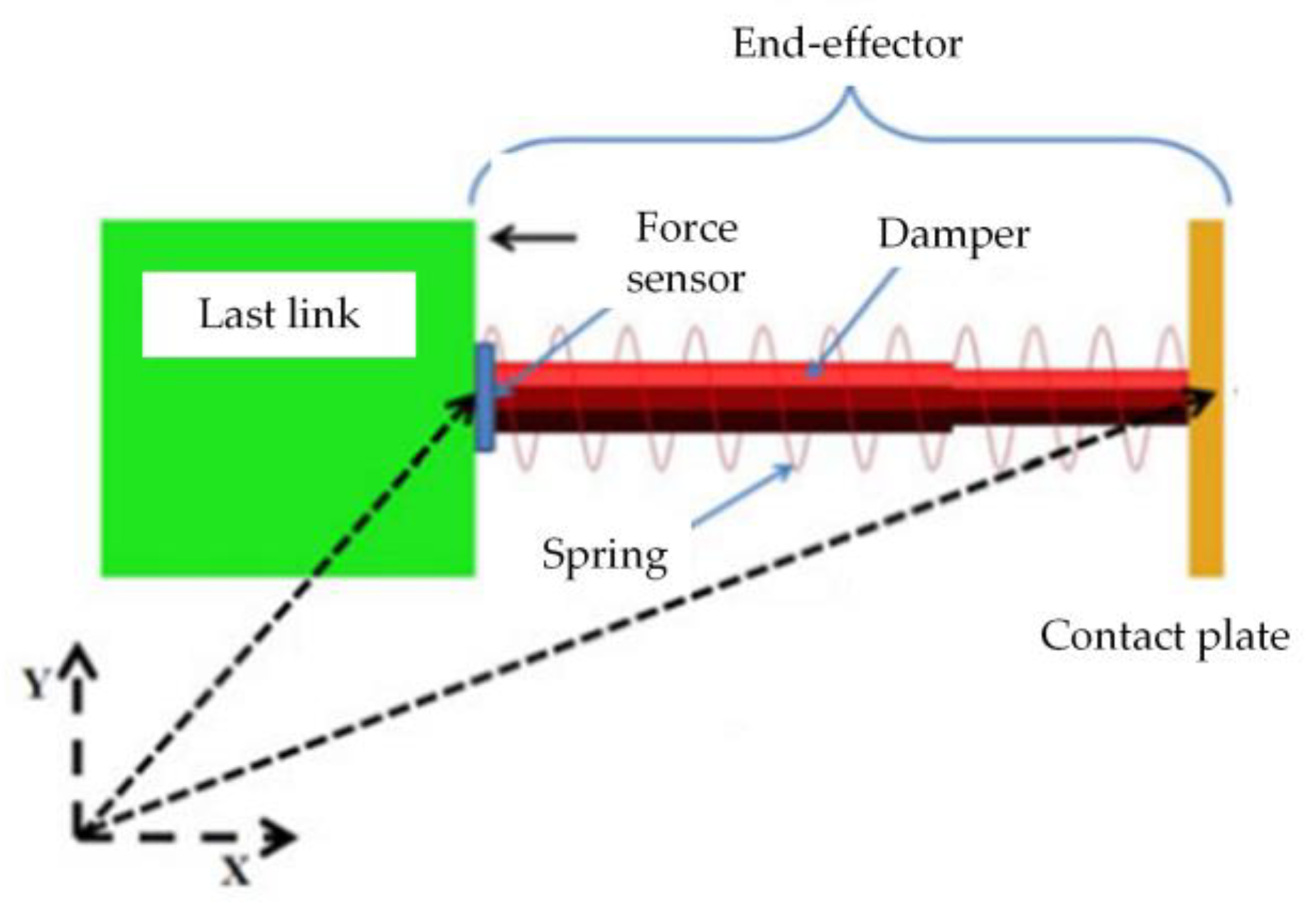
| [43] | √ | Use a Mass-spring-damping System | ||||||
| [46] | √ | Convex Quadratic Programming | ||||||
| [47] | √ | CCDJAP-IK | ||||||
| [49] | √ | AccPF | ||||||
| [50] | √ | - | ||||||
| [52] | √ | Based on C-space Topology | ||||||
| [53] | √ | Two-way Heuristic Search Method | ||||||
| [55] | √ | FTWLCC | ||||||
| [56] | √ | Combine the Dynamic Window | ||||||
| [59] | √ | - | ||||||
| [60] | √ | A New Time-scale Transformation | ||||||
| [61] | √ | Improved RRT | ||||||
| [62] | √ | Combine with APF | ||||||
| Planning Space | Characteristics | Solution | Binding | Application Scenarios |
|---|---|---|---|---|
| Joint Space | The calculation is simple; no redundancy and singularities [64]. However, there are errors in the end trajectories [65]. | Joint values | Initial and end states | Robotic arm running in orbit; truss movement; target pushing, etc. |
| Cartesian Space | The planning is intuitive and highly accurate [66]. However, the number of inversions is high and computationally intensive; singularities exist [67]. | End position | Continuous paths | In-rail repair; surface machining tasks; in-rail assembly of trusses, etc. |
| Planning Method | Specific Implementation Method | Reference |
|---|---|---|
| Basic Spatial Trajectory Planning | High-order Polynomial Parameterization | [69] |
| 6th and 7th Order Interpolation | [70] | |
| 5th and 6th Order Interpolation | [71] | |
| Polynomial Smooth Continuous Function | [72] | |
| Constrained Differential Evolution Scheme | [79] | |
| Modify Bézier Curve Shape | [81] | |
| Third consecutive Bezier Curve | [82] | |
| Optimal Trajectory Optimization | Genetic Algorithm | [87] |
| Genetic Algorithm | [88] | |
| Genetic Algorithm | [89] | |
| Genetic Algorithm | [90] | |
| Particle Swarm Optimization | [93] | |
| Multi-objective Particle Swarm Optimization | [94] | |
| Chaotic Particle Swarm Optimization | [95] | |
| Particle Swarm Optimization | [96] | |
| Multi-objective Particle Swarm Optimization | [97] | |
| Particle Swarm Optimization | [98] | |
| Sarsa(λ) Intensive Learning | [100] | |
| Dynamic Movement Primitives | [101] | |
| Based on the Actor-Critic Algorithm Framework | [102] | |
| Deep Deterministic Policy Gradient | [103] | |
| Deep Deterministic Policy Gradient | [104] | |
| Deep Deterministic Policy Gradient | [106] | |
| Based on the Actor-Critic Algorithm Framework | [108] | |
| Soft Value Iteration Network | [109] | |
| Consisting of Step Iterations and Block Iterations | [110] | |
| Deep Convolutional Neural Networks | [111] |
Publisher’s Note: MDPI stays neutral with regard to jurisdictional claims in published maps and institutional affiliations. |
© 2022 by the authors. Licensee MDPI, Basel, Switzerland. This article is an open access article distributed under the terms and conditions of the Creative Commons Attribution (CC BY) license (https://creativecommons.org/licenses/by/4.0/).
Share and Cite
Dai, Y.; Xiang, C.; Zhang, Y.; Jiang, Y.; Qu, W.; Zhang, Q. A Review of Spatial Robotic Arm Trajectory Planning. Aerospace 2022, 9, 361. https://doi.org/10.3390/aerospace9070361
Dai Y, Xiang C, Zhang Y, Jiang Y, Qu W, Zhang Q. A Review of Spatial Robotic Arm Trajectory Planning. Aerospace. 2022; 9(7):361. https://doi.org/10.3390/aerospace9070361
Chicago/Turabian StyleDai, Ye, Chaofang Xiang, Yuan Zhang, Yupeng Jiang, Wenyin Qu, and Qihao Zhang. 2022. "A Review of Spatial Robotic Arm Trajectory Planning" Aerospace 9, no. 7: 361. https://doi.org/10.3390/aerospace9070361
APA StyleDai, Y., Xiang, C., Zhang, Y., Jiang, Y., Qu, W., & Zhang, Q. (2022). A Review of Spatial Robotic Arm Trajectory Planning. Aerospace, 9(7), 361. https://doi.org/10.3390/aerospace9070361