Article

Numerical Investigation of the Aerofoil Aerodynamics with Surface Heating for Anti-Icing

1
Department of Aeronautics, Imperial College London, London SW7 2BX, UK
2
Department of Mechanical, Materials and Manufacturing Engineering, University of Nottingham, Nottingham NG7 2RD, UK
3
School of Aerospace Engineering, Beijing Institute of Technology, Beijing 100081, China
*
Authors to whom correspondence should be addressed.
These authors contributed equally to this work.
Aerospace 2022, 9(7), 338; https://doi.org/10.3390/aerospace9070338
Submission received: 2 May 2022 / Revised: 11 June 2022 / Accepted: 15 June 2022 / Published: 24 June 2022
(This article belongs to the Special Issue Aerodynamics Design)

Abstract

:
The aerodynamics of an aerofoil with surface heating was numerically studied with the objective to build an effective anti-icing strategy and balance the aerodynamics performance and energy consumption. NACA0012, RAE2822 and ONERA M6 aerofoils were adopted as the test cases and the simulations were performed in the subsonic flight condition of commercial passenger aircraft. In the first session, the numerical scheme was firstly validated with the experimental data. A parametric study with different heating temperatures and heating areas was carried out. The lift and drag coefficients both drop with surface heating, especially at a larger angle of attack. It was found that the separation point on the upper surface of the aerofoil is sensitive to heating. Higher heating temperature or larger heating area pushes the shock wave and hence flow separation point moving towards the leading edge, which reduces the low-pressure region of the upper surface and decreases the lift. In the second session, the conclusions obtained are applied to inform the design of the heating scheme for NACA0012. Further guidelines for different flight conditions were proposed to shed light on the optimisation of the heating strategy.

1. Introduction

Icing in flight presents a severe hazard leading to numerous aircraft crash catastrophes. A database of 645 accidents and incidents from 1978 to 2002 were reported in a study of U.S. inflight icing [1]. According to another database from AOPA Air Safety Foundation, 12% of the weather accidents from 1990 to 2000 were related with icing [2]. Icing changes the aerodynamic configuration of the wing, adds significant surface roughness to the leading edge (LE), disturbs the smooth flow around the fore-part of the wing, decreases lift, and increases drag [3]. The icing can cause roll control problems when ice accretion is asymmetric on the wing. The plane then stalls at a much higher speed and a lower angle of attack (AOA) than normal. The ice accretion process is characterised by the presence of supercooled droplets entrained in the flow around the wing, fuselage and antenna, etc. These droplets impinge upon the body surface and coalesce into larger drops driven by the surface tension. The larger drops flow along the surface under the effects of airflow and gradually freeze on the aircraft’s surface below the freezing temperature. Anti/de-icing system is therefore indispensable during the flight. De-icing refers to the destruction and elimination of the ice layer by physical or chemical methods after the ice is formed on the wing. The anti-icing systems, on the other hand, are designed to prevent ice accretion, which can be categorized into mechanical-based, chemical-based and thermal-based [3], which is the target of the present work.
Among the different designs of the anti-icing systems, thermal anti-icing is a common choice due to its maturity and ongoing success in large commercial aircraft (e.g., Boeing 737 or the Airbus A320 [4]). The anti-icing system in Boeing 737-300/400/500 uses the hot bleed air extracted from the compressor stage. The hot air runs through a pre-cooler to reduce the temperature to 200 C and is distributed via the bleed ducts to the wing anti-icing system. However, some challenges still exist to achieve an even broader prospect in the future. Firstly, bleed air systems require high energy levels and re-freezing is still a problem. Moreover, newer aircraft with high-performance jet engines do not provide sufficient bleed air for deicing [5]. The total weight of the flight increases as the heat demand becomes larger. The fuel consumption is therefore increased [6] which makes it essential to optimise the energy consumption on duty. Efforts have been devoted into the performance improvement and heat load optimisation of the thermal anti-icing system [7,8]. It is proposed that reducing the heating intensity of non-critical areas can save energy and alleviate the adverse influence on aerodynamic performances [9]. But there is still a lack of clear guidance on the configuration of energy-efficient heating schemes especially in different flight conditions. Secondly, an important drawback of the heating system is that it almost indispensably leads to reduced aerodynamic performances of the wing (e.g., drop of the lift) [10,11,12]. For example, the temperature change of the wing surface affects the stall angle [13] and boundary-layer transition [14]. While the region of 10% chord from the LE is most susceptible to droplet collision icing [15,16], the heating at the LE generates more significant adverse effects in aerodynamics [17]. Therefore, how to reduce the impact of the heating while maintaining the anti-icing effect still needs to be explored.
Based on the above challenges in the application of thermal anti-icing systems, this study aims to figure out how surface heating changes the aerodynamic characteristics of the wing in different flight conditions and propose a design strategy accordingly. Such a strategy can provide a useful reference to instruct the design, seeking a balance between flight safety and economics. The objectives of this research are listed below:
(1) Investigate the effect of heating temperature and heating area on the lift and drag of a wing.
(2) Figure out the mechanism of how the surface heating changes the wing aerodynamic performance.
(3) Obtain instructive design principles of the heating system to achieve an energy-efficient scheme whilst maintaining aerodynamic performances.
(4) Apply the design principles to a demo case in a true flight condition.

2. Methodology

The investigation was carried out using two-dimensional numerical simulations in this study. The mesh is generated with Ansys ICEM-CFD and Fluent is used to solve the Reynolds-averaged Navier-Stokes (RANS) equations [18]. Such a setup is chosen due to its low computational cost for a parametric study with acceptable accuracy. The mass conservation equation is written as follows:
ρ t + · ( ρ v ) = 0 ,
where ρ is the density, v is the velocity. The momentum equation is described by:
( ρ v ) t + · ( ρ v v ) = p + · ( τ ¯ ¯ ) + ρ g ,
where p is the static pressure, τ ¯ ¯ represents the viscous stress tensor, and ρ g is the gravitational force. Based on the previous work [15], realizable k- ϵ turbulence model is adopted with enhanced wall functions as it can obtain reliable lift coefficient for a heated aerofoil.
The energy equation in the following form is solved:
( ρ E ) t + · ( v ( ρ E + p ) ) = · ( k e f f T + τ e f f ¯ ¯ · v ) + S ,
where k e f f is the effective thermal conductivity, T is the temperature and τ e f f ¯ ¯ · v represents the viscous dissipation. S is the heat source on the blade surface.
NACA0012 aerofoil is adopted in a subsonic civil flight condition matching the cruise case of Airbus A320, since it is one of the most common commercial aircraft in modern civil aviation. The chord length is set as the wing area divided by wingspan which equals 3.6 m. The cruise velocity of A320 is 511 MPH (230 m/s) with an altitude of around 9000 m [19]. The air density at this altitude drops to 0.467 kg/m 3 , and the atmospheric temperature is 229.65 K, which leads to a Reynolds number:
R e = ρ v l μ = 2.6 × 10 7 .
The corresponding dynamic viscosity μ is 1.492 × 10 5 kg/(m · s) obtained with the Sutherland law [20]:
μ μ 0 = ( T T 0 ) 3 / 2 T 0 + S μ T A + S μ ,
where S μ is 110.56 K, T 0 is 273.15 K, μ 0 is 1.716 × 10 5 kg/(m · s) [18]. The eddy viscosity is computed from:
μ t = ρ C μ k 2 ε ,
where C μ is a function of the mean strain and rotation rates, the angular velocity of the system rotation, and the turbulence fields (k and ε ). The turbulence intensity ( T I ) of the far-field is set to:
T I = 0.16 R e 1 / 8 = 1.894 % ,
and the relative inflow Mach number is:
M = v c = v 331.3 T A 273.15 = 0.757 ,
where c is the speed of sound in the flight condition.
During the simulation, pressure boundary inflow condition is used for the far-field where the static pressure, static temperature, AOA and Mach number can be specified. Viscous wall is adopted for the wing surface. For the cases with surface heating, an isothermal boundary condition is adopted for the wing surface. The physical properties changes with the local temperature.
To achieve specific non-uniform heat intensity distribution along the wing, the simulation domain for both geometries is equally divided into ten blocks along the chord as shown in Figure 1. Different heating strengths are tested on each block in the following numerical study. This is based on the modern electro-thermal heating system (e.g., the electro-thermal technology applied on Boeing 787 Dreamliner), where the temperature distribution on the wing surface can be accurately controlled. A larger number of blocks can be used in the real design of the heating system.
The heating temperature is determined based on the historical design data of wing anti-icing. Considering the energy consumption and faster heat dissipation with higher heating intensities, the difference between surface temperature and ambient temperature is typically less than 150 C [21]. Therefore, in this study the wing surface temperature relative to the ambient is set to Δ T = 0 K, 50 K, 100 K, 150 K, 200 K when the heat exchange between the aerofoil surface and airflow reaches an equilibrium state.
Figure 2 shows the structured mesh created in each block of NACA0012. The y+ is 0.4 3 and the total number of nodes is around 30,000.

3. Case Validation

3.1. NACA0012

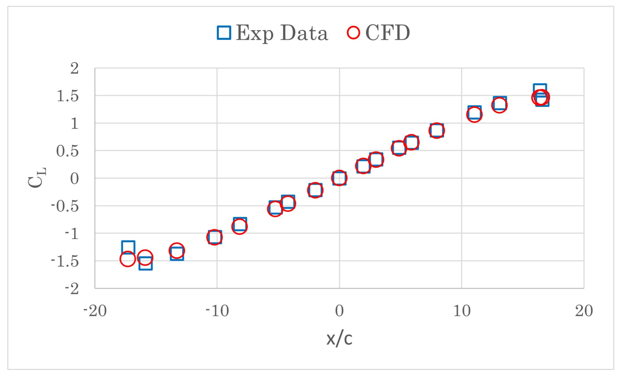
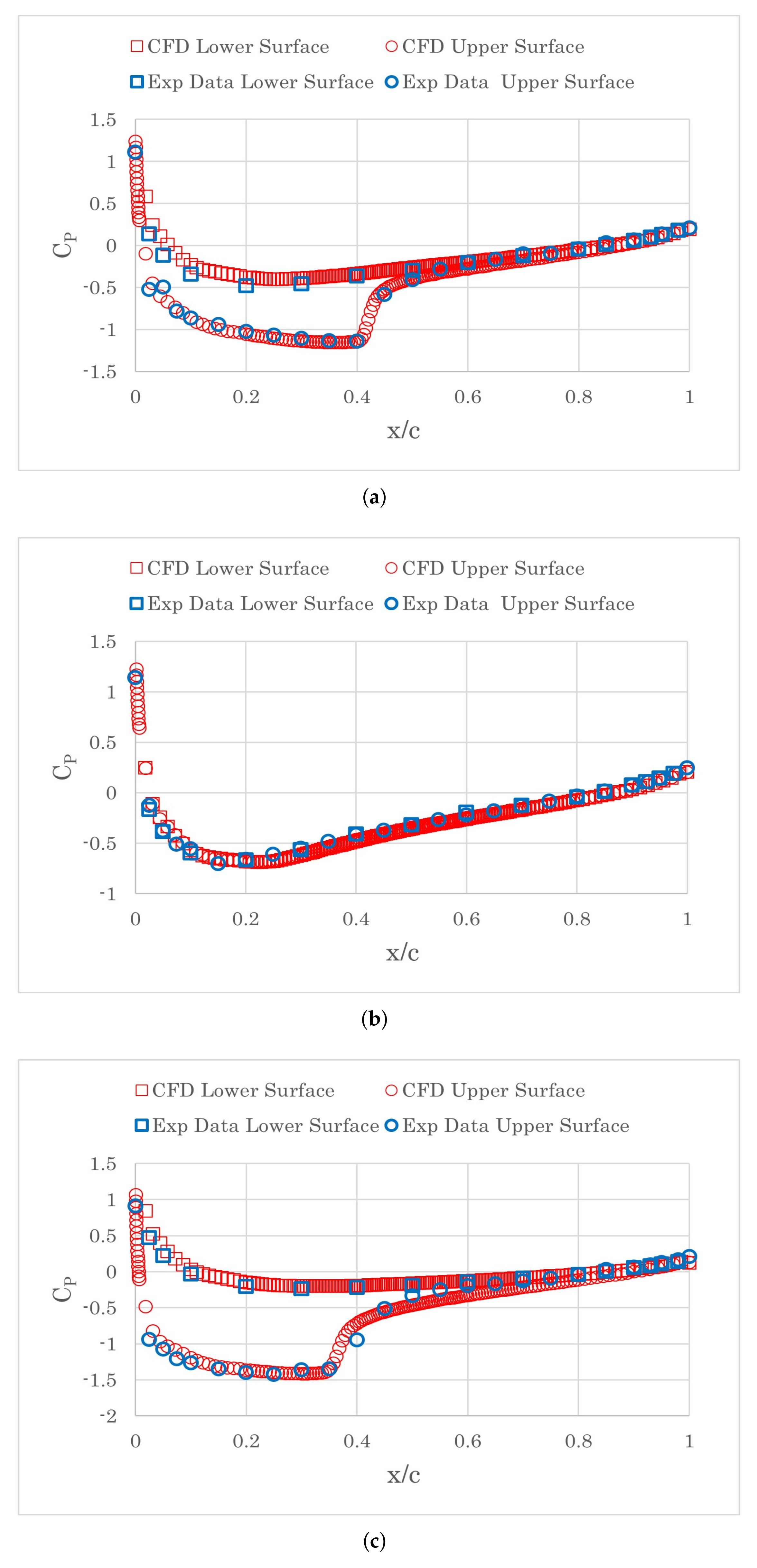
To validate the numerical scheme used in this work, simulations are carried out to compare against the experimental data in this section. The key objective is to estimate the performance of the simulation in terms of the lift coefficient and the shock wave position. As no open-accessed experimental data with surface heating for NACA0012 is available, the numerical scheme is validated with the experimental tests without heating. The validation are performed in both low-speed ( M a = 0.15 ) and high subsonic conditions ( M a > 0.7 ). In the low-speed cases, the change in the aerofoil lift coefficient and drag coefficient with the AOA [22] is accurately captured by the simulations (Figure 3). The simulated pressure coefficient on both sides of the aerofoil in the high subsonic flow [23] is plotted against the experimental data in Figure 4. The Mach number varies from 0.732 to 0.759 and the AOA increases from 0 degrees to 4 degrees. Good matches are obtained between the simulations and experimental data, which proves the adopted numerical scheme can satisfactorily reproduce the position of the shock waves on the upper surface of the wing.

3.2. RAE2822

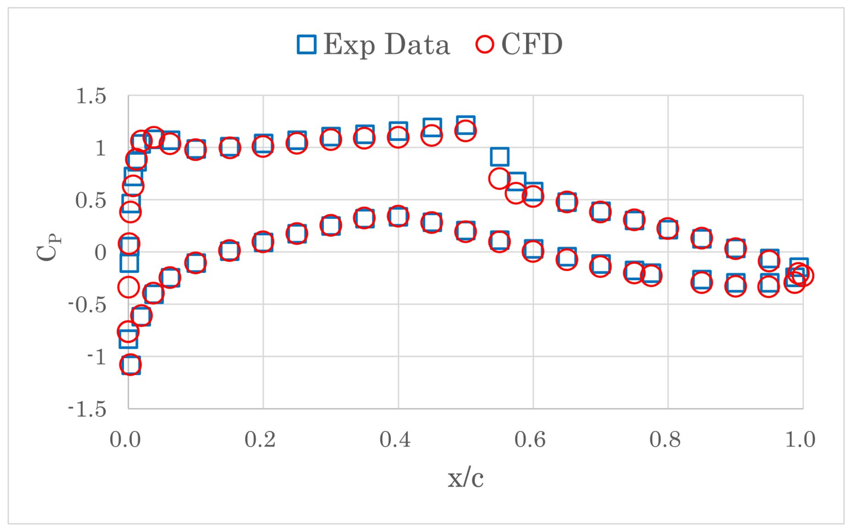
The second test case, RAE2822, is a supercritical wing [24] with transonic flow on the suction surface. The chord length of the wing is 0.61m. The simulated Mach number is 0.729 with the attack angle of 2.31 or RAE2822. The experiment was carried out with a static pressure of 10,8987 Pa. The flow temperature is 255.56 K and the air density is 1.486 kg/m 3 . The mesh topology and numerical strategy for NACA0012 are used for the simulation of RAE2822. Figure 5 shows the computed pressure coefficients against the measured data on the airfoil. Again, the CFD results accurately capture the flow field around the wing.
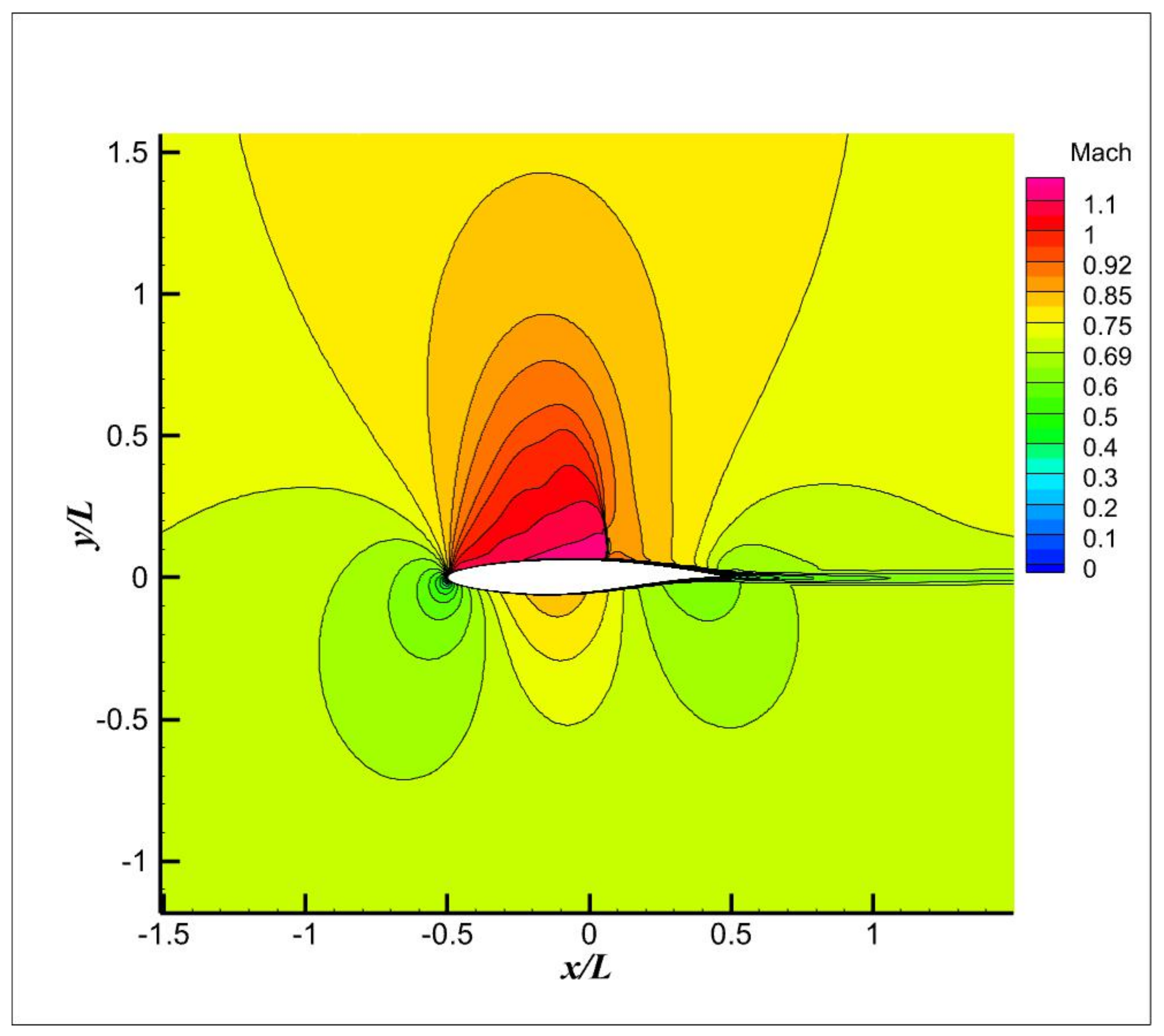
The Mach number contour of the flow field for RAE 2822 is shown in Figure 6. The computed result obtain good match with [25]. The shock wave on the upper surface can clearly be seen.

3.3. ONERA M6 Wing

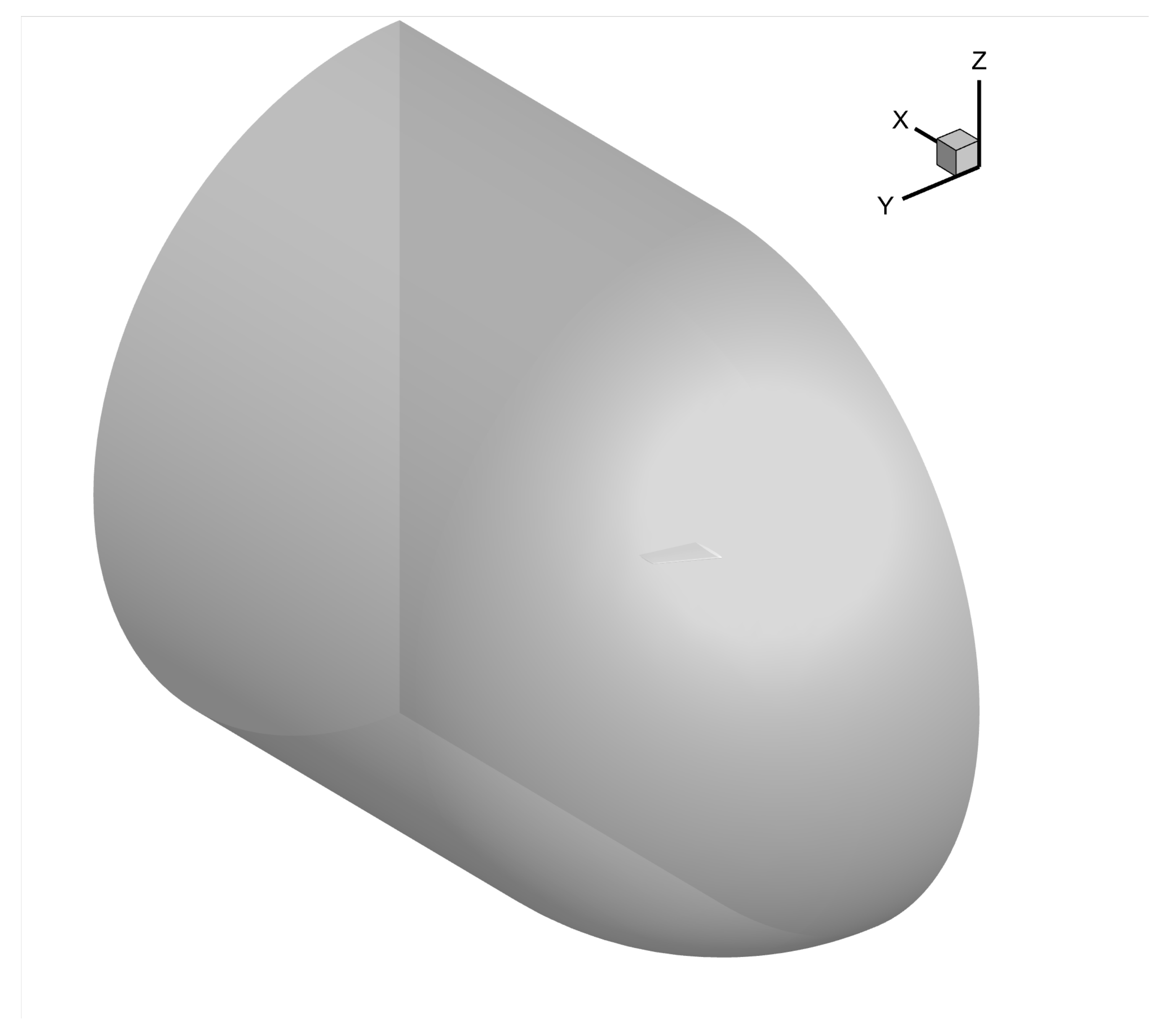
The ONERA M6 wing is a widely used 3D transonic test case for CFD validation [26]. To validate the numerical scheme used in this work, two different AOAs ( α = 3 . 06 and α = 6 . 06 ) are performed with the ONERA M6 wing. The boundary conditions used in the CFD are exactly in accordance with the test environment in the wind tunnel. The Mach number of the inflow is 0.84 and the temperature is 300 K. The other setup is the same as the numerical scheme used for the 2D simulations. The simulation domain (Figure 7) contains 11 million mesh points. The distance from the wing to the far-field boundary is ten times of the root chord length. To accurately capture the surface pressure and the shock wave, the y+ value of the first layer mesh along the wing surface is less than 1.
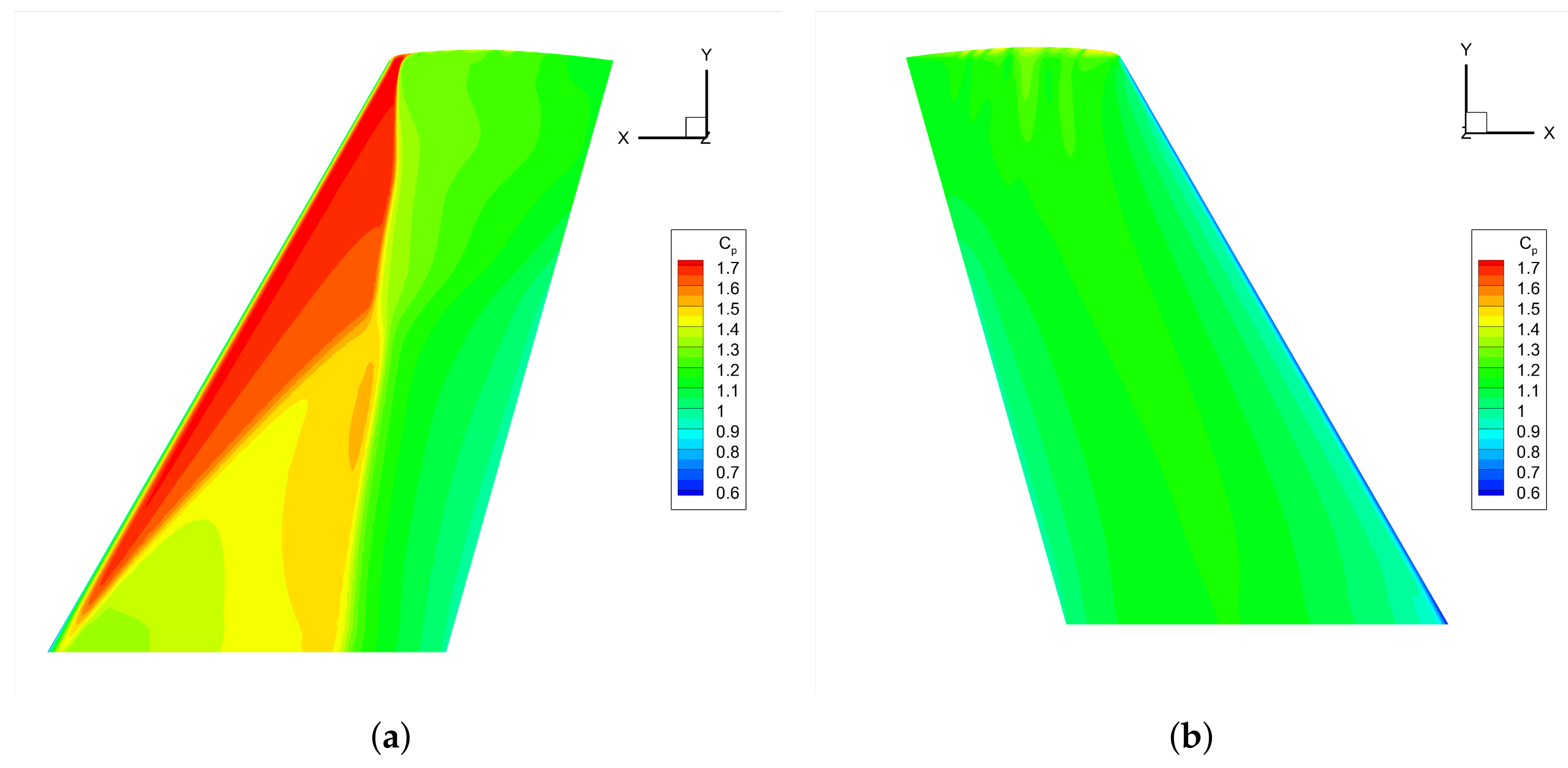
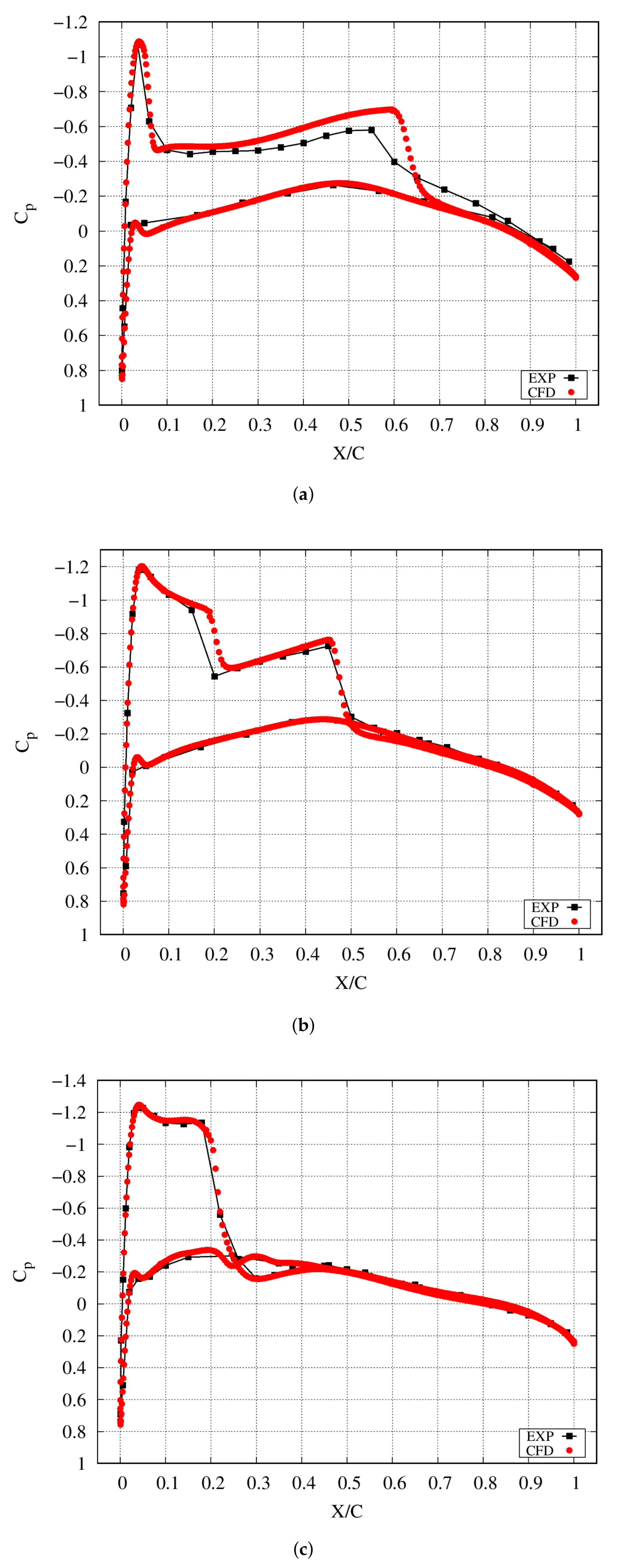
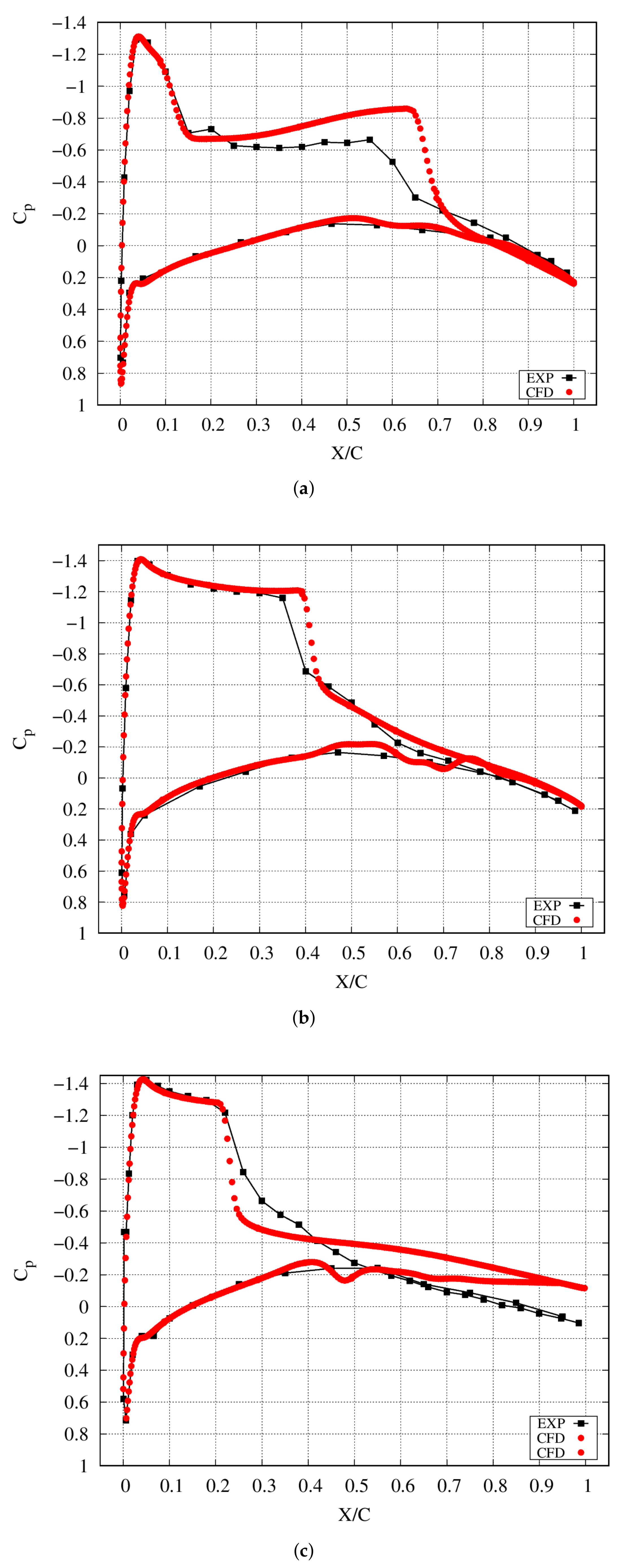
Figure 8 shows the pressure coefficient of the upper and lower surface of the wing for the case with α = 6 . 06 . The simulated pressure coefficient on the wing surface at 20 % , 65 % and 96 % span from the root are compared against the experimental data for the case with α = 3 . 06 , as shown in Figure 9. And the simulated pressure coefficient at 20 % , 65 % and 90 % span from the root are plotted against the experimental data for the case with α = 6 . 06 in Figure 10. For the case with the lower AOA, the simulated flow field matches well with the test data, while the flow pattern near tip region slightly deviates from the test data at the higher AOA. The position of the shock wave on the wing surface for both cases are accurately captured in the numerical results.

4. Results

4.1. NACA0012

4.1.1. Unheated Flow

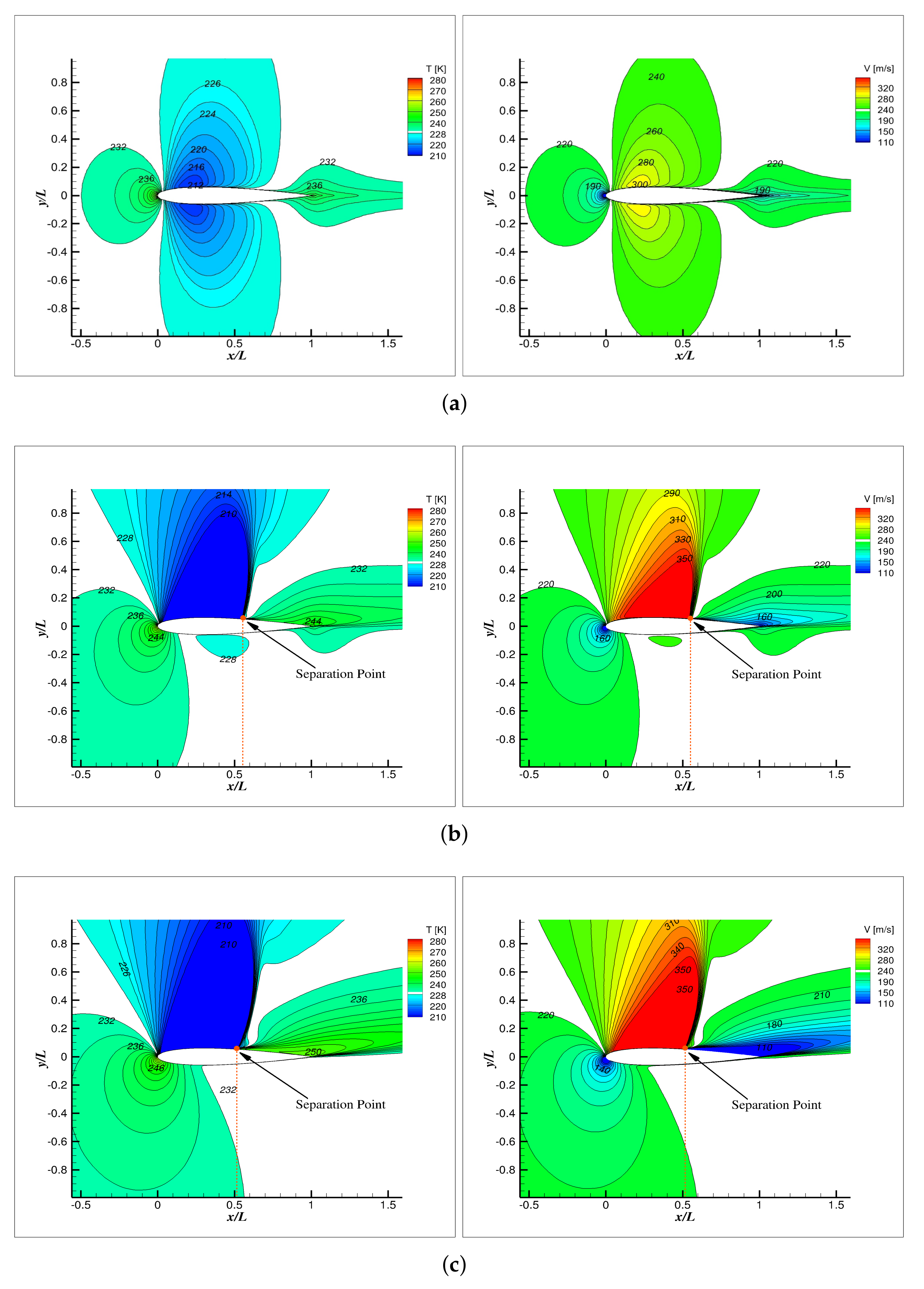
In this section, the NACA0012 without surface heating at the AOA α = 0 , 5 and 9 was simulated to get the baseline flow field. The flow velocity and temperature are plotted in Figure 11.
Inspecting the temperature contours of the flow at α = 0 , it can be seen that the temperature in the first 50% chord (starting from the LE) of the aerofoil is relatively lower than the ambient temperature due to the flow acceleration. The flow temperature near LE and trailing edge (TE) is slightly higher than the ambient air due to the flow stagnation and deceleration, respectively. When α increases to 5 degrees, the temperature above the upper surface at the first 50% chord is even lower than that when α = 0 . The flow velocity in this area is further accelerated and the maximum speed is up to 388 m/s, which is over the sound speed of 304 m/s at this altitude. A shock wave can be clearly distinguished accompanied by flow separation directly downstream along the wing upper surface. A further increase in the AOA pushes the shock wave upwind accompanied by the movement of the separation point, which is indicated by the dashed line in Figure 11b,c.

4.1.2. Uniform Surface Heating

To figure out how the surface heating affects the main features of the flow field, two different heating patterns, namely, uniform heating on the entire wing surface and non-uniform heating on part-chord will be tested. The surface heating temperature varies from 50 K to 250 K with a 50 K interval.
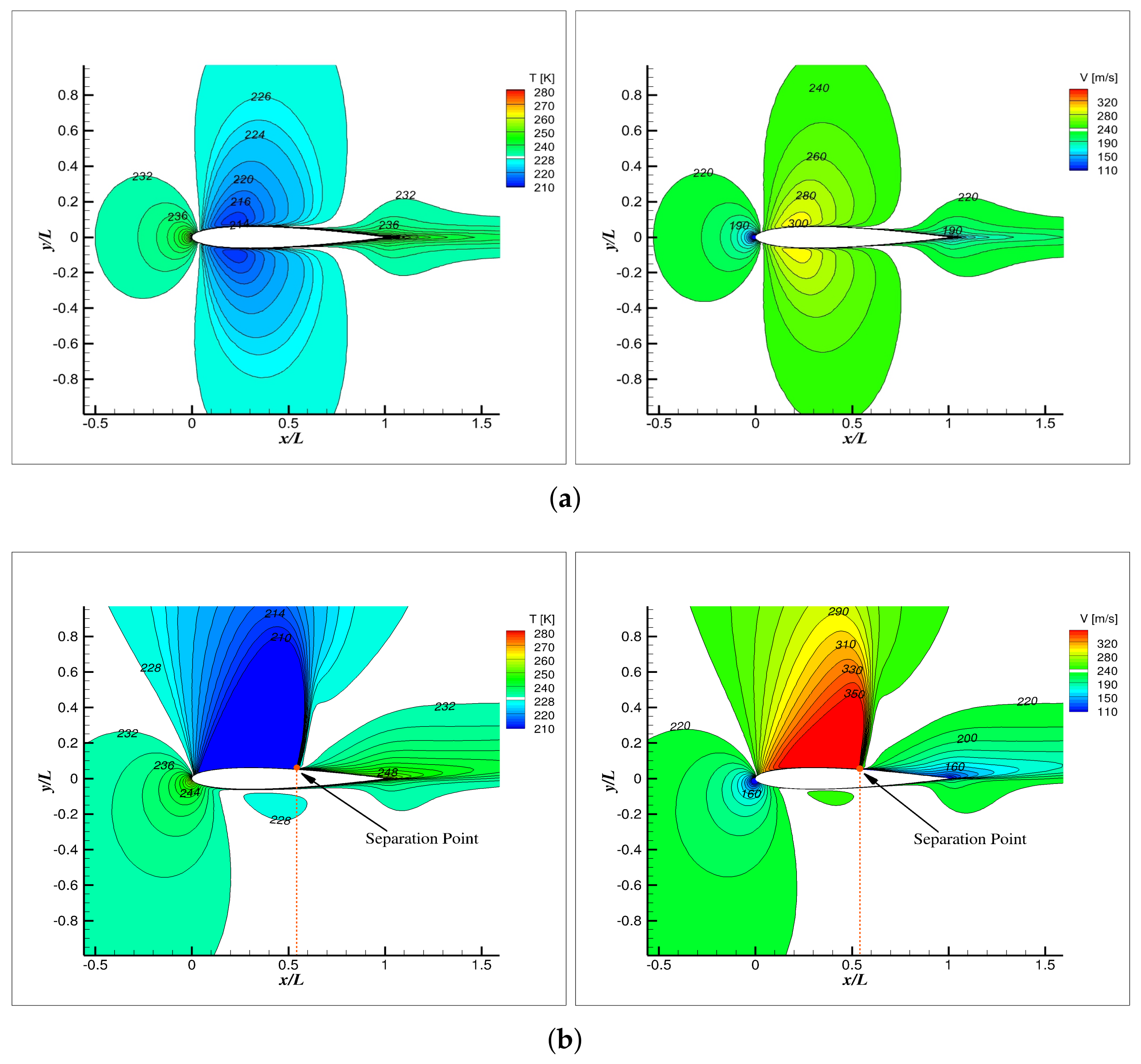
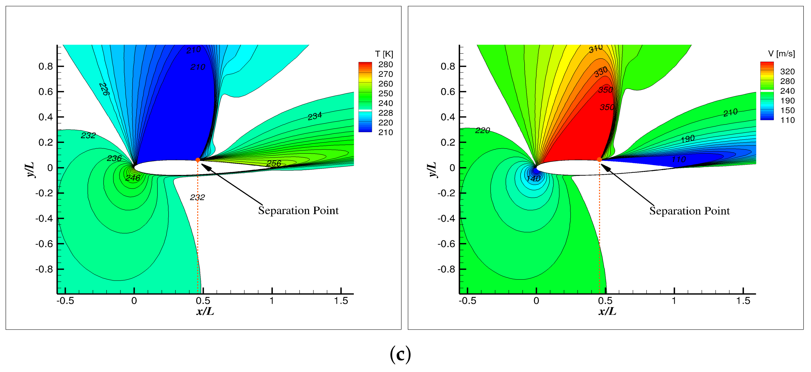
In this section, the flow field of the first heating pattern with surface temperature Δ T = 100 K is analysed. The temperature and flow velocity distribution are shown in Figure 12. For the case α = 0 , it can be found that the surface heating only slightly increases the near-wall temperature while the overall temperature distribution is not affected. There is no visible change in the velocity compared with the case without heating (Figure 11a). A similar observation can be found when α = 5 . The position of the shock waves stays almost unchanged. The influence of surface heating on the shock wave is quite weak when α is small. But as α increases to 9 in Figure 12c, an obvious shift in the separation point can be observed compared with Figure 11c. The performance of the aerofoil in terms of the lift coefficient and drag coefficient is significantly changed at larger AOA as shown in Figure 13. It is observed that the lift coefficient and the stall angle (dashed line) decrease with the rise of heating temperature, which again confirms that the surface heating can reduce the performance of the aerofoil. The drag coefficient is relatively less sensitive to heating though it also decreases.

4.1.3. Non-Uniform Part-Chord Surface Heating

Considering that the ice accretion is not uniform along the chord of the aerofoil, the heat flux to prevent the formation of ice can be varied accordingly. To achieve better anti-icing effects, the heating can be applied with a larger intensity at the critical regions where ice accretion is prone to occur. In this section, instead of heating the entire aerofoil surface, heat flux is only provided in a limited region with a constant temperature to figure out its influence on the aerofoil aerodynamic performance. The previous experimental study has shown that the LE of the aerofoil is the most vulnerable position to icing and the ice accretion gradually reduces along the chord to TE [8]. The heating area in this study is denoted by the percentage of the blade chord starting from the LE. For instance, “10% heating area” means the first 10% chord marked as the red curve shown in Figure 1. The other heating patterns are defined in the same way. The heating temperature is fixed at 200 K above the atmosphere temperature. The simulated lift coefficient and drag coefficient with α = 0 13 are displayed in Figure 14. A few observations can be summarised as follows: First, both lift coefficient and drag coefficient decrease as the heating area becomes larger. This observation is in accordance with the result with different heating temperatures in Figure 13. Second, the drop in the lift coefficient is almost linear with the increase of the heating area within a certain range (<30%). When the heating area exceeds 40%, a big loss can be seen in the lift coefficient and stall angle. This indicates that the heating between 40%∼50% chord leads to critical flow features and subsequently alters the overall performance. The underlying mechanism will be explored in the next section. Third, the lift coefficient becomes insensitive to the AOA after at post-stall condition when the heating area exceeds 50%. This trend is also observed in the drag coefficient.

4.1.4. Mechanism of Surface Heating on Aerofoil Performance

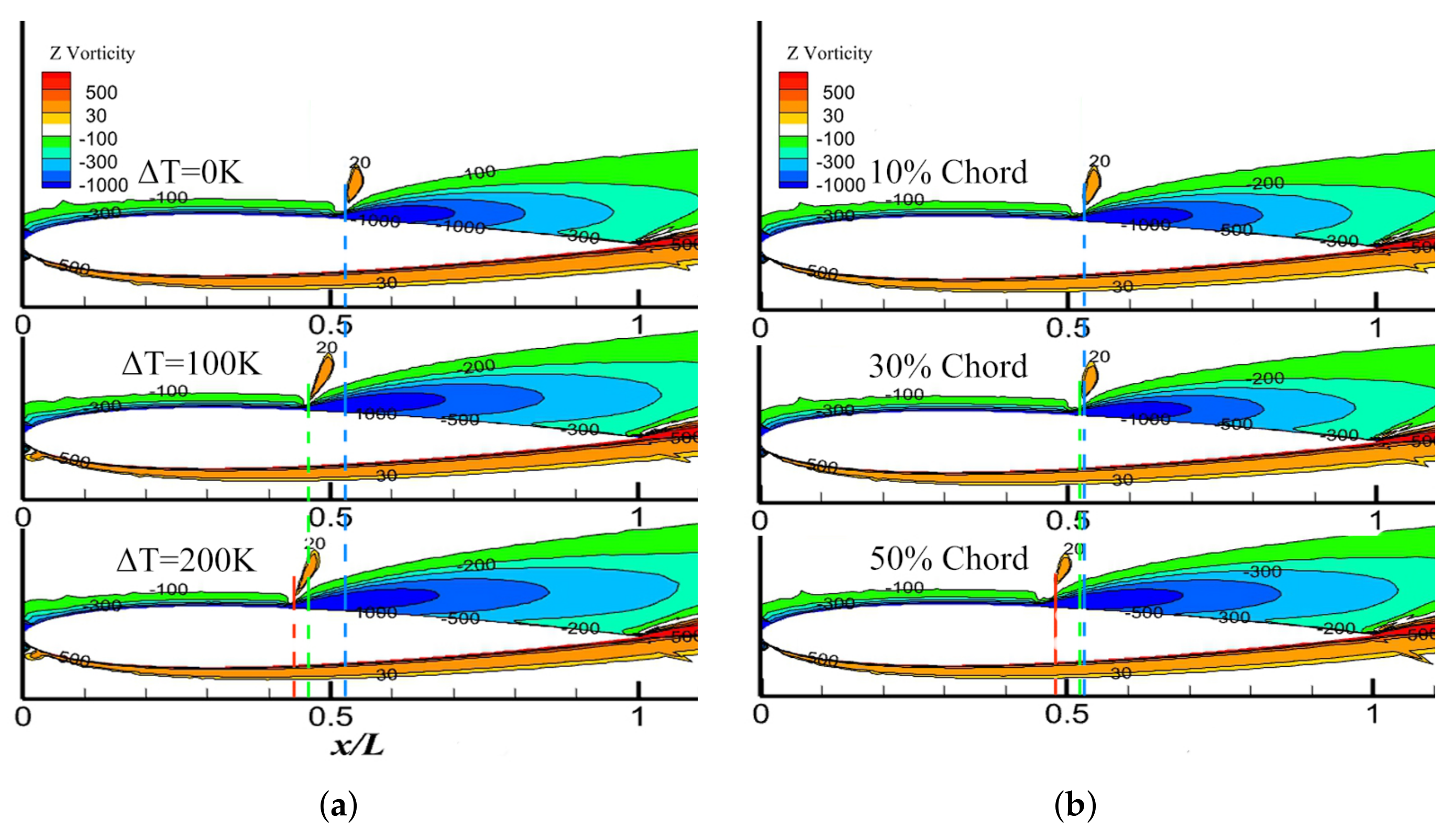
To uncover the underlying mechanism of the heated aerofoil performance with different heating temperatures and areas studied in Section 4.1.2 and Section 4.1.3, the shock wave and surface pressure with and without heating are analysed. The flight condition at α = 9 is chosen because a significant difference in lift and drag coefficient can be seen (Figure 13 and Figure 14). The cases with uniform surface heating of Δ T = 0 K, 100 K, and 200 K and the case with non-uniform part-chord heating (10%, 30% and 50%) of Δ T = 200 K are shown in Figure 15.
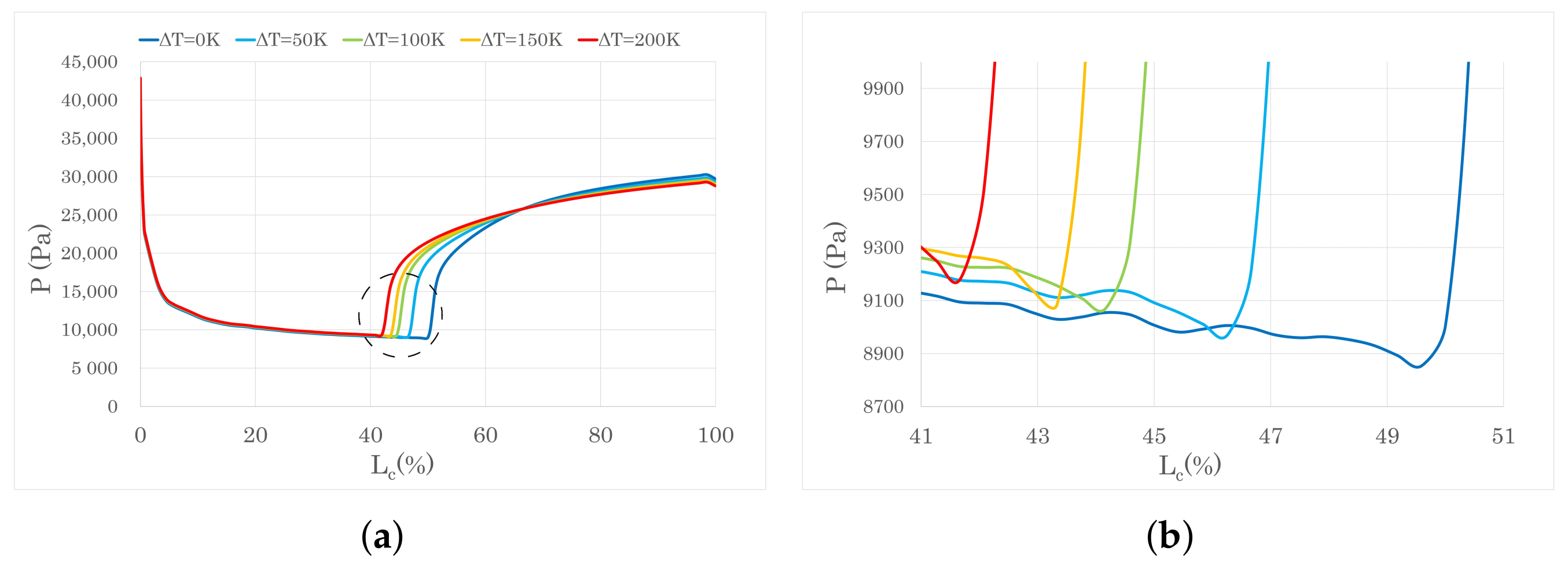
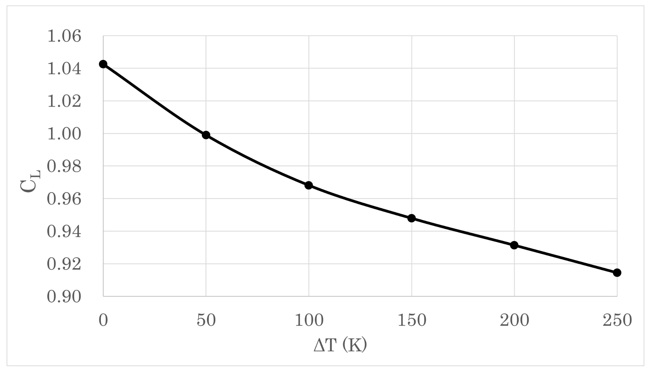
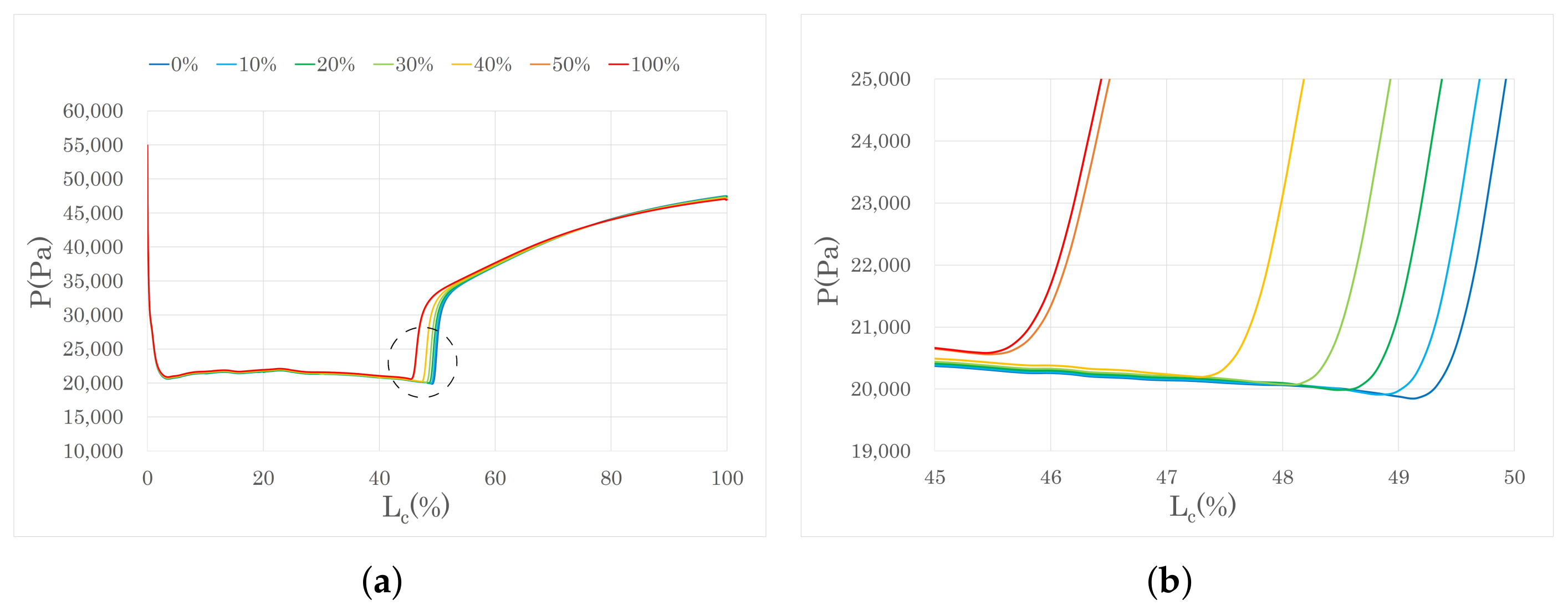
The yellow region on the upper surface denotes the position of the shock wave. Again it can be found that the shock wave moves forward as the heating temperature increases in Figure 15a. This forward movement of the shock wave pushes the separation point of the boundary layer to move towards the LE. The surface pressure distribution is consequently changed which is closely related to the generation of aircraft lift. Figure 16 shows the surface pressure at the upper surface with different uniform heating temperatures. The surface heating changes the size of the low-pressure region on the upper surface starting from the LE by shifting the separation point, which is pushed towards the LE with a higher heating temperature. No obvious change occurs in the lower surface pressure, and hence it is not shown in the figure. As part of the lift comes from the pressure difference between the upper and lower surfaces, the shift of the separation point reduces the low-pressure area on the upper surface and hence the lift coefficient. In addition, the movement of the separation point is not linear with the temperature rise. It is more sensitive at lower heating temperatures. This phenomenon is also shown in Figure 17, where the lift coefficient is plotted against the heating temperature. The slope of the curve is steeper when the heating temperature is lower.
In Figure 15b, there is hardly any change in the flow field until the heating area increases to 50%. A close inspection of the upper pressure distribution with different part-chord heating patterns in Figure 18 reveals that there is a drastic drop in the low-pressure region at the upper surface when the heating area increases from 40% to 50%. This is due to the separation point is just within this critical region(red line in Figure 15b) and its movement by heating results in significant lift loss shown in Figure 14. As the heating area extends further downstream (50%, 60% and 100%), the pressure distribution and the lift coefficient will no longer change.

4.1.5. The Heating Strategy for NACA0012

For the purpose of energy saving, the typical heating system maintains high heating intensity at the position where ice is prone to form whilst leaving the other parts unprotected. However, considering high-intensity heating is harmful to the in-flight performance, decreasing the heating temperature but increasing the total heating area (with comparable total heating power) is preferred. To instruct the design of the heating system to achieve satisfactory anti-icing capability while maintaining high lift coefficient, two different heating strategies are proposed and examined: increasing surface heating temperature within limited heating area or increasing surface heating area with low heating temperature.
To obtain a functional and energy-saving heating strategy, this session is organised as follows: Firstly, the two above-mentioned strategies are compared, and the better option is selected. Secondly, the appropriate heating temperature and area are determined. At last, further improvements of the scheme at different flight conditions (i.e., different AOA and cruise speeds) are discussed. As the change in the drag coefficient with surface heating is less significant, priority is given to the lift coefficient when assessing its aerodynamics performance.
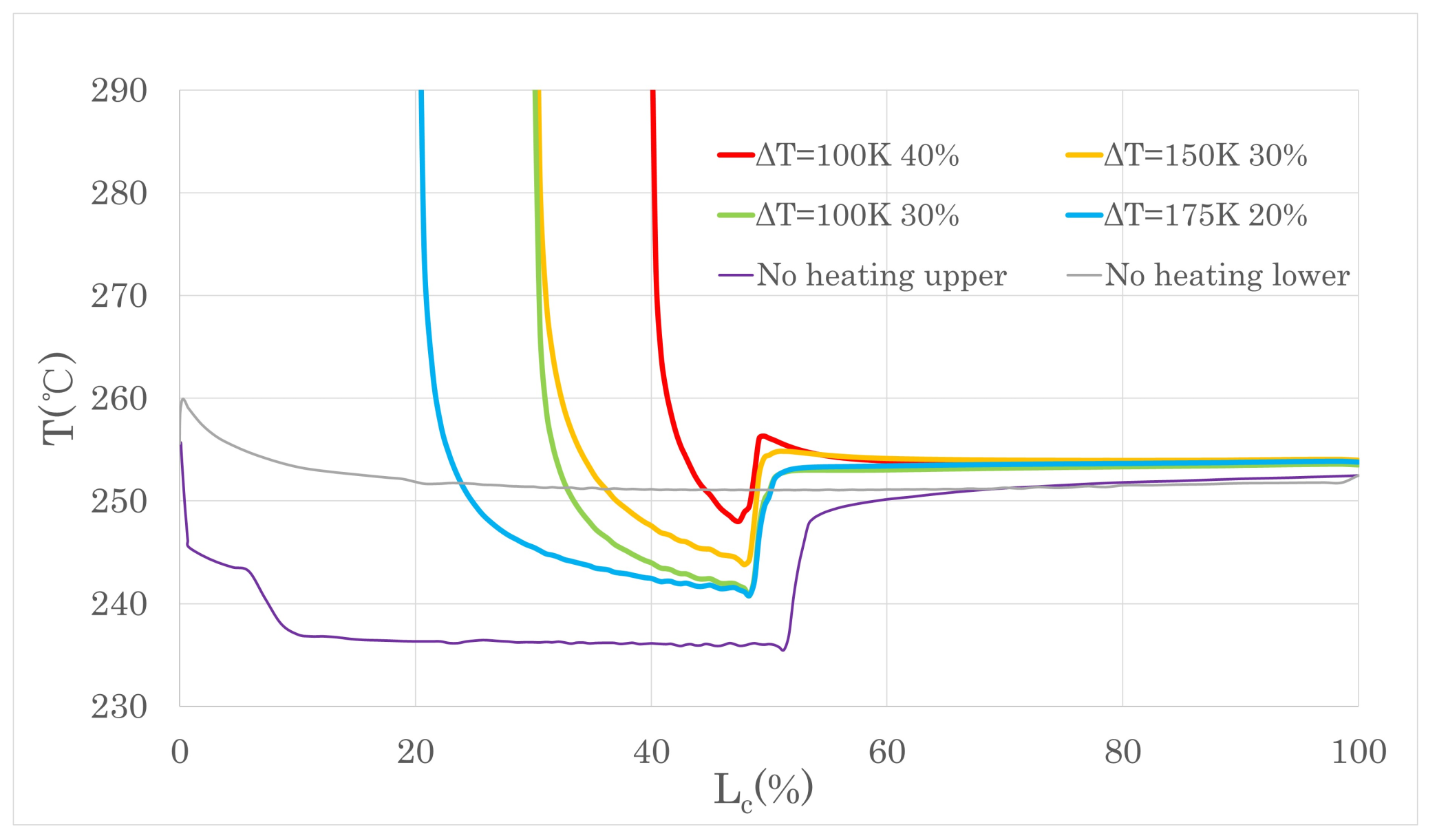
The flow field of NACA0012 is simulated at α = 9 with different combinations of the heating temperature and heating area corresponding to the two strategies. Figure 19 shows the upper surface temperature for different heating temperatures and areas together with the baseline case without heating. Table 1 summarises the lift and drag coefficient of these test cases. When the total heating power is the same, the second strategy is more prominent in terms of near-wall temperature and lift coefficient. For example, the temperature curve of 100 K with 40% heating area is basically above the curve of 150 K with 30% heating area and the lift coefficient of the former is higher. The same conclusion can be obtained in the case of 100 K with 30% heating area versus the curve of 175 K with 20% heating area.
It is worth mentioning that it was attempted to increase the temperature to a very high value near the LE of the wing to heat the airflow passing through. It was expected that the air can be heated to a high temperature and release heat when it flows over the unprotected downstream surface (without heating) to prevent icing. Nevertheless, it is unachievable in the simulation as the low-temperature airflow passes the LE very fast and there is no sufficient time for the air to be heated. In addition, the flow separation which occurs downstream of the shock hinders the air from warming up the downstream surface.
After the “low temperature-large heating area” strategy is selected, the heating temperature and heating area can be determined. A previous study has shown that the mid-chord of the aerofoil is less vulnerable to ice accretion [27], and heating can be removed in this region to reduce the energy consumption. Therefore, the heating area of the upper surface is limited to 40%. Regarding the lower surface, Figure 12 shows that the near-wall temperature of the lower surface is higher than the upper surface even without heating, and there is generally no ice accumulation in the region downstream of 30% chord [8]. Consequently, heating is only applied in the first 30% chord area on the lower surface. Regarding the heating temperature, it can be set just higher than the icing temperature to achieve an anti-icing effect [8]. The highest temperature of icing is 10 0 C [15,16] above which no ice can be accreted. In this study, the lowest heating temperature Δ T = 50 K in the simulation is chosen (6.5 C). This lowest heating temperature may vary with flight conditions and thus can be adjusted in the actual design. The first 10% chord area needs to be heated with a higher temperature Δ T = 100 K. The temperature distribution of the final heating scheme is shown in Figure 20. It can be seen from Table 2 that while the uniform heating scheme decreases the lift coefficient, the optimal heating scheme can maintain the aerodynamic performance compared to the uniform heating scheme in the same flight condition.
Moreover, the heating area and the heating intensity on both surfaces need to be adjusted dynamically in different flight conditions: on one hand, the icing area gradually extends downstream along the chord on the lower surface and shrinks on the upper surface when α increases [16]. It changes in the opposite way when α decreases. On the other hand, the cruise speed can influence the icing range and thickness on the wing surface because the collision velocity and the total amount of supercooled water droplets increase when the flight speed is higher [16].

4.2. RAE2822

To demonstrate the generality of the observations with NACA0012, the simulation with RAE2822 is performed at α = 5 . 0 with the Mach number of 0.729. The air density is 0.6601 kg/m 3 and the temperature is 249.19 K to mimic the environment at the height of 6000 m, at which icing can occur on the wing surface. All the following results are performed with the same heating strategy as NACA0012.
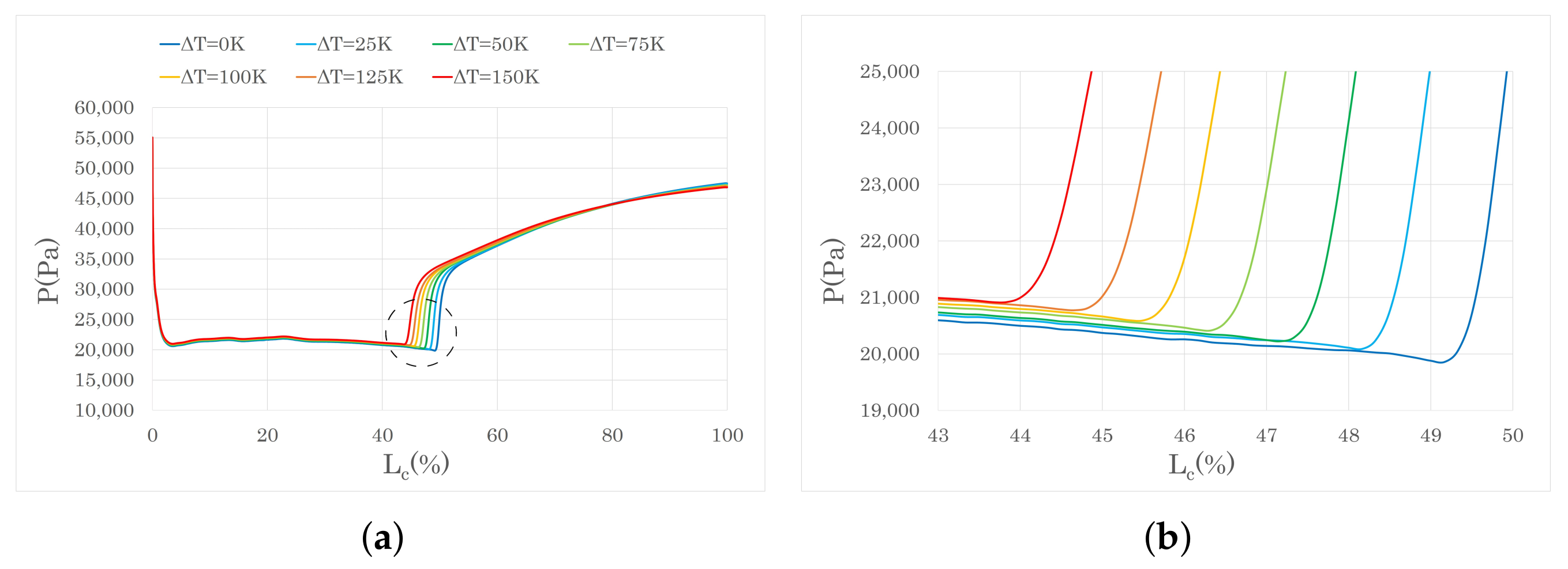
Figure 21 shows the surface pressure at the upper surface with different uniform heating temperatures. The result is similar to that in Figure 16 that the size of the low-pressure region on the upper surface shrinks with a higher heating temperature with the movement of the separation point.
Similar to the results in Figure 18, it can be seen that as the heating area increases, the movement of the LE low-pressure region gradually reduces (Figure 22). Significant change is the low-pressure region occurs when the heating areas reaches the separation point but there is no obvious difference with 50% and 100% surface heating.

4.3. ONERA M6 Wing

To validate the conclusions obtained from the 2D simulations of NACA0012 and RAE2822, the 3D computations with ONERA M6 wing at α = 6 . 06 with surface heating are performed. The inflow Mach number remains 0.84. The density and temperature of the air are the same with that used in the RAE2822 case. Thus the real meteorological icing environment is modelled to investigate the performance of the wing with surface heating.
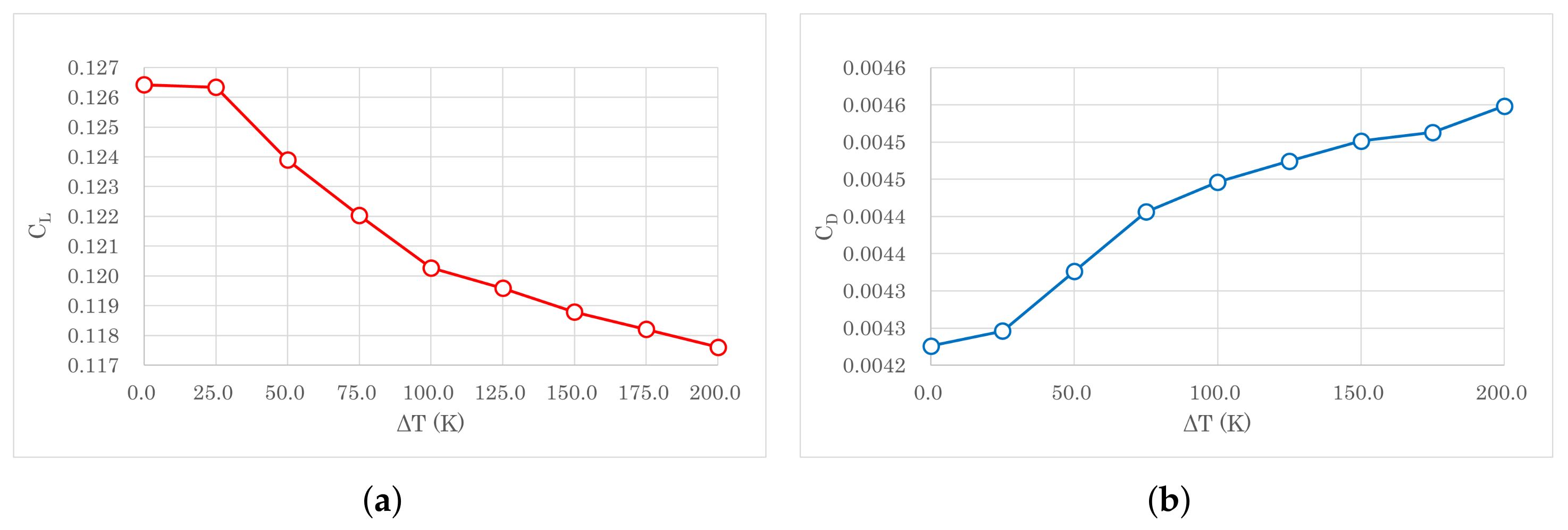
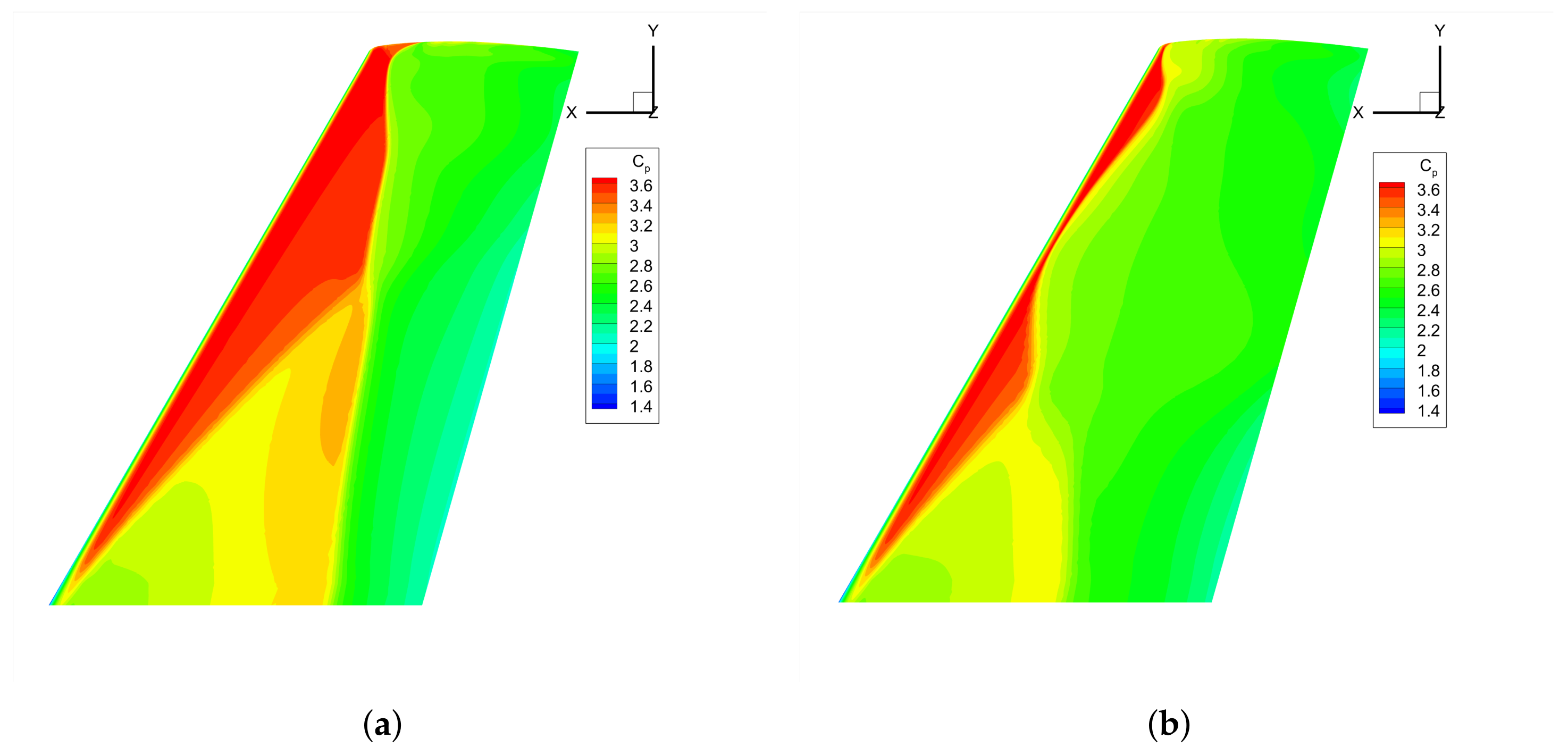
To find out how the performance of the wing change with the heating strength, the lift coefficient and drag coefficient against different uniform surface heating (the tip of the wing is not heated.) temperature are plotted in Figure 23. As the observation in 2D test, the lift coefficient of the wing drops as the surface temperature increases. Again, this is because the surface heating can shift the position of the shock wave and hence the wing performance. A more straightforward demonstration of the movement of the shock wave can be seen in Figure 24, where the upper pressure coefficient of the wing without surface heating and with a uniform surface heating of Δ T = 200 K is plotted. It can be clearly seen that the shock wave moves towards the LE with surface heating. This confirms that the 3D simulations are in accordance with the 2D results on the interactions between surface heating and the movement of the shock wave. However, the drag coefficient becomes slightly larger with higher heating temperature, which is opposite to the trend found in 2D simulations.
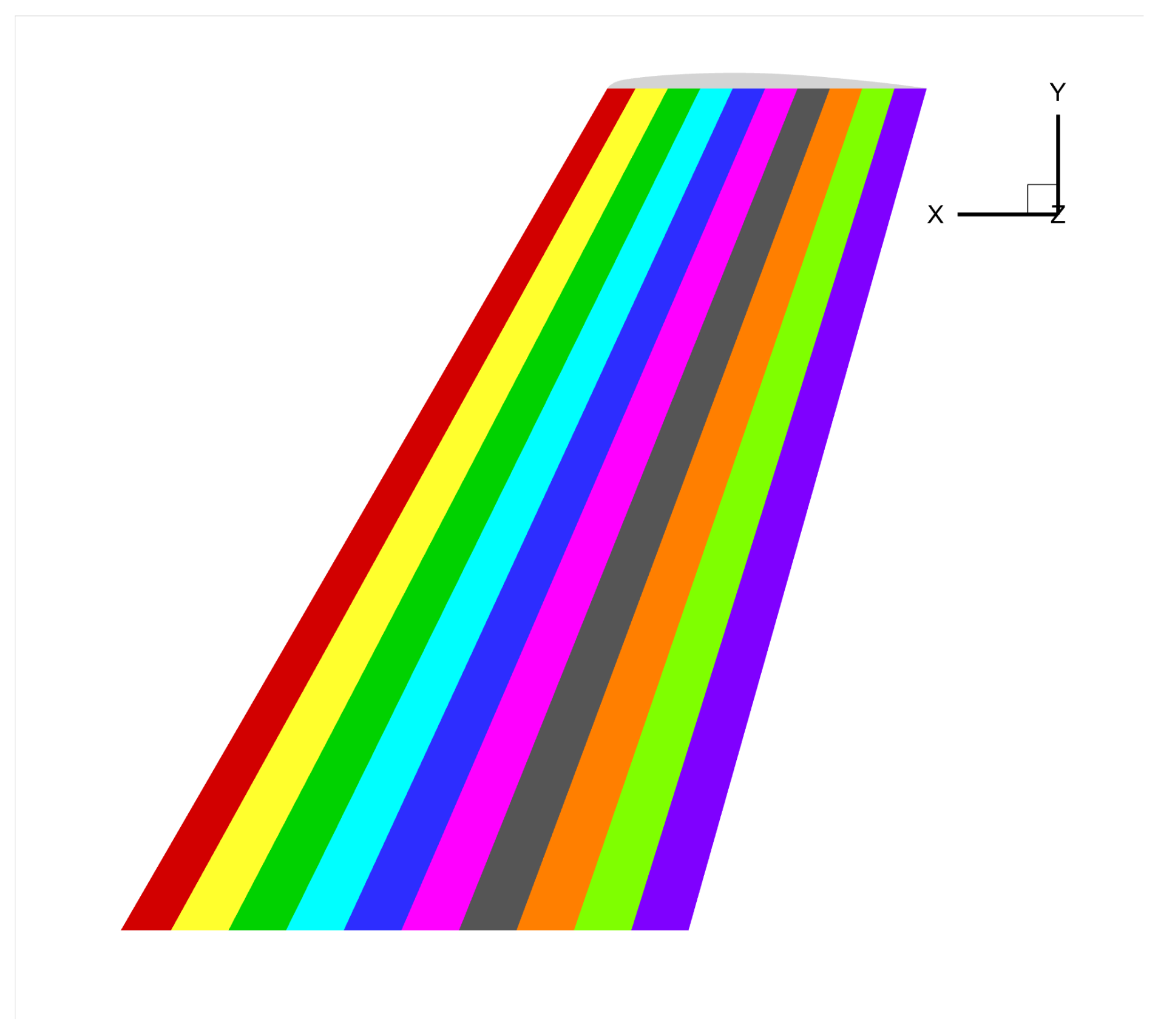
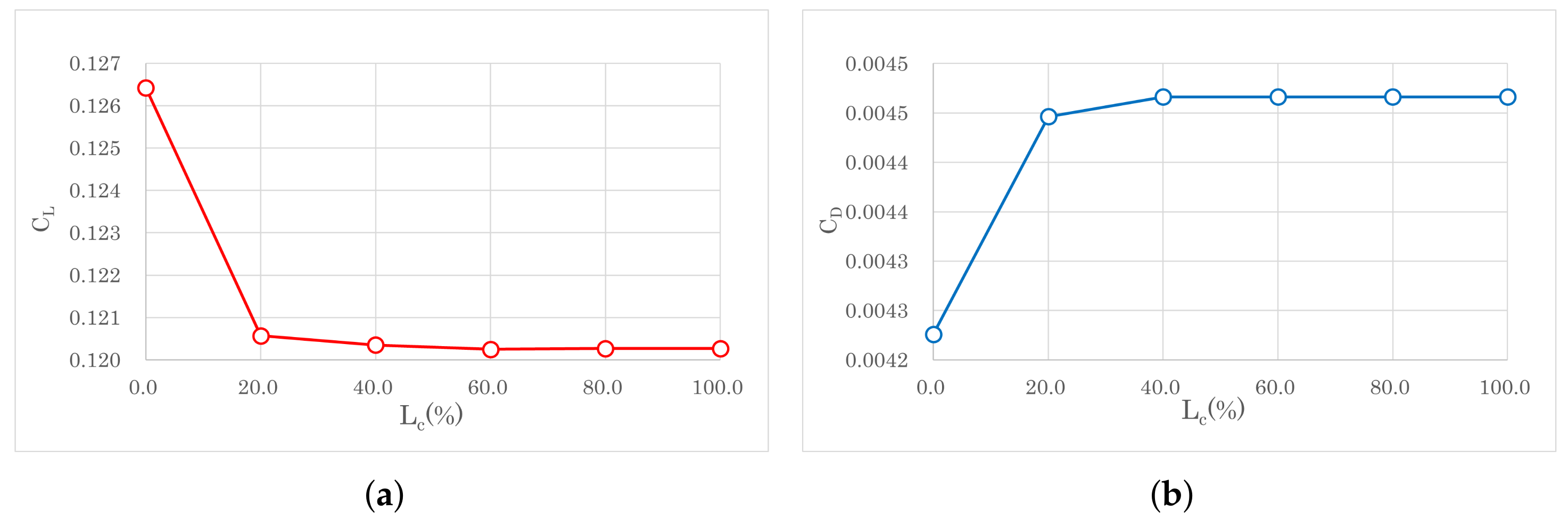
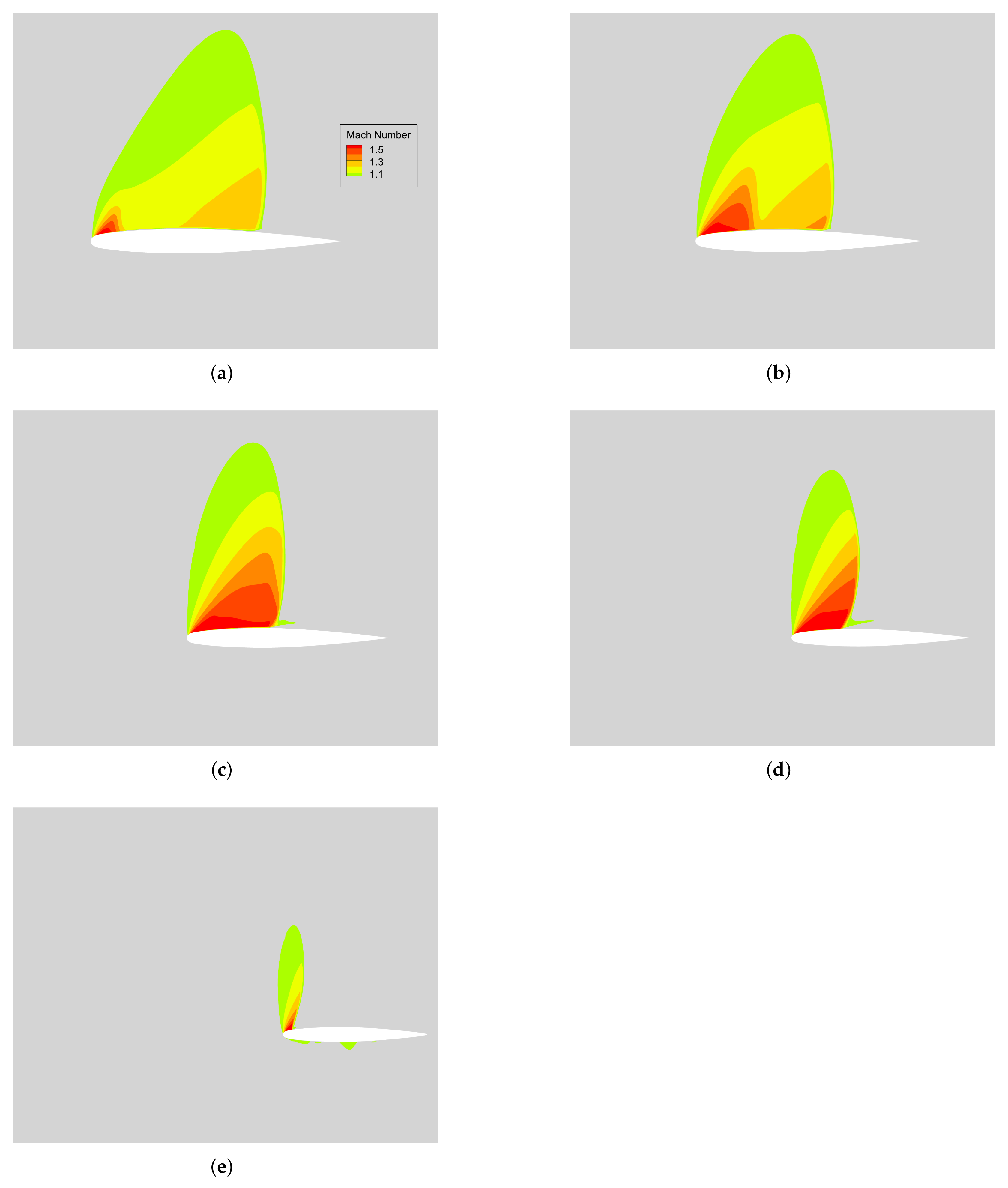
With the purpose to find out how the heating area influences the performance of the wing, the non-uniform part-chord surface heating scheme is adopted. As shown in Figure 25, the wing surface is uniformly split into 10 sections along the chord. The heating temperature of the wing surface is fixed to Δ T = 100 K. Figure 26 shows heating area of the first 40% chord with Δ T = 100 K. The lift coefficient and drag coefficient of different heating area are plotted in Figure 27. Both parameter has significant change when the heating area extends from LE to 60% chord and remain almost unchanged when it extends further towards the TE. As displayed in Figure 8 and Figure 28, the shock wave mainly sits between the LE and 60% chord (55.8% chord in Figure 28a). Therefore, the wing surface pressure distribution is more sensitive to the surface heating within the region between LE and 60% chord. In addition, the low pressure region is (the higher Mach number region) mainly located at the first 20% chord near LE. It can be seen that the lift drops most with heating in this region as shown in Figure 27.

5. Conclusions

Thermal anti-icing systems attract considerable attention in subsonic commercial flight. In this study, numerical simulations were adopted to investigate the influence of heating on the aerodynamic performance of NACA0012, RAE2822 and ONERA M6 in different flight conditions. The numerical scheme is validated with the experimental data and a good agreement is obtained. The conclusions obtained with both geometries in this study can be applied to other aerofoils to facilitate the design and application of the electro-thermal ice protection system, and are summarised as follows:
1. Surface heating decreases the lift and drag coefficient along with the stall angle of the wing. The adverse effects become stronger when the heating temperature or the heating area increases. The influence of heating is weak at lower AOA ( α < 5 ) but it becomes more significant when the AOA is larger.
2. The underlying mechanism of the heating-induced performance change is the displacement of the boundary layer separation point on the upper surface. As the heating intensity increases, the shock wave at the upper surface moves forward towards the LE, which shifts the separation point, reduces the low-pressure region and the lift drops accordingly.
3. The separation point is sensitive to surface heating at larger AOA. The heating close to the separation point on the upper surface will drastically decrease the lift coefficient.
4. Considering the aerodynamic performance and the energy consumption, a “low-temperature and large-area" heating scheme is proposed for future designs and the simulated result shows it can maintain the aerodynamic performance of the aerofoil. It is suggested that the heating area should not extend beyond the separation point. Further suggestions on the heating system optimisation in different flight conditions are discussed.
5. Regarding the effect of surface heating on the lift coefficient and shock wave movement, the prediction of two-dimensional simulations agree well with three-dimensional simulations. However, it is shown that the drag coefficient drops in two-dimensional simulations while the three-dimensional simulation indicate that the drag coefficient slightly increases.
The fast development of the electrical thermal heating system makes it possible for precise, real-time control of the heating on the wing surface. Based on this study, an intelligent wing thermal anti-icing system is proposed for future investigations: surface heating is automatically controlled through a computer processor based on real-time signals from sensors. The heating area and intensity are adjusted when the angle of attack, cruise speed, and ambient temperature change during the flight. Reliable control algorithms need to be developed and validated in wind tunnel tests to achieve the best anti-icing effects with minimum energy consumption. In addition, the flow turbulence can affect the near-wall heat transfer and the accurate prediction of the separation point, but it cannot be well resolved with RANS. Further study will adopt large eddy simulation coupled with unsteady icing modelling to verify and improve the anti-icing scheme developed in this work.

Author Contributions

Conceptualization, W.Z.; validation, B.L. and Q.S.; formal analysis, B.L.; writing—original draft preparation, D.X.; supervision, W.Z. All authors have read and agreed to the published version of the manuscript.

Funding

This research received no external funding.

Institutional Review Board Statement

Not applicable.

Informed Consent Statement

Not applicable.

Data Availability Statement

Some or all data, models, or code that support the findings of this study are available from the corresponding author upon reasonable request.

Conflicts of Interest

The authors declare no conflict of interest.

Abbreviations

The following abbreviations are used in this manuscript:
LELeading Edge
AOAAngel of Attack
RANSReynolds-averaged Navier-Stokes
TETraling Edge
TITurbulence Intensity

References

  1. Green, S. A study of US inflight icing accidents and incidents, 1978 to 2002. In Proceedings of the 44th AIAA Aerospace Sciences Meeting and Exhibit, Reno, NV, USA, 9–12 January 2006; p. 82. [Google Scholar]
  2. Foundation, A.A.S. Aircraft Icing. In Proceedings of the Safety-Advisors, AOPA Air Safety Foundation 421 Aviation Way, Frederick, MD, USA, 8–14 May 2008; p. 16. [Google Scholar]
  3. Pourbagian, M.; Habashi, W.G. Aero-thermal optimization of in-flight electro-thermal ice protection systems in transient deicing mode. Int. J. Heat Fluid Flow 2015, 54, 167–182. [Google Scholar] [CrossRef]
  4. Filburn, T. Anti-ice and Deice Systems for Wings, Nacelles, and Instruments. In Commercial Aviation in the Jet Era and the Systems that Make it Possible; Springer: Berlin/Heidelberg, Germany, 2020; pp. 99–109. [Google Scholar]
  5. Goraj, Z. An overview of the deicing and anti-icing technologies with prospects for the future. In Proceedings of the 24th International Congress of the Aeronautical Sciences, Yokohama, Japan, 29 August–3 September 2004; Volume 29. [Google Scholar]
  6. Pourbagian, M.; Talgorn, B.; Habashi, W.G.; Kokkolaras, M.; Le Digabel, S. Constrained problem formulations for power optimization of aircraft electro-thermal anti-icing systems. Optim. Eng. 2015, 16, 663–693. [Google Scholar] [CrossRef]
  7. Al-Khalil, K.; Horvath, C.; Miller, D.; Wright, W.; Al-Khalil, K.; Horvath, C.; Miller, D.; Wright, W. Validation of NASA thermal ice protection computer codes. III-The validation of ANTICE. In Proceedings of the 35th Aerospace Sciences Meeting and Exhibit, Reno, NV, USA, 6–9 January 1997; p. 51. [Google Scholar]
  8. Li, R.; Zhu, G.; Zhang, D. Investigation on the Mechanism of Heat Load Reduction for the Thermal Anti-Icing System. Energies 2020, 13, 5911. [Google Scholar] [CrossRef]
  9. Kim, J.; Rusak, Z.; Koratkar, N. Small-scale airfoil aerodynamic efficiency improvement by surface temperature and heat transfer. AIAA J. 2003, 41, 2105–2113. [Google Scholar] [CrossRef]
  10. Kazakov, A.; Kogan, M.; Kuparev, V. Optimization of laminar-turbulent transition delay by means of local heating of the surface. Fluid Dyn. 1995, 30, 563–570. [Google Scholar] [CrossRef]
  11. Landrum, D.; Macha, J. Influence of a heated leading edge on boundary layer growth, stability, and transition. In Proceedings of the 19th AIAA, Fluid Dynamics, Plasma Dynamics, and Lasers Conference, Honolulu, HI, USA, 8–10 June 1987; p. 1259. [Google Scholar]
  12. Blohm, R.W. Heat Transfer Effects on a Subsonic Delta Wing. Ph.D. Thesis, Virginia Polytechnic Institute and State University, Blacksburg, VA, USA, 1973. [Google Scholar]
  13. Norton, D.J.; Macha, J.M.; Young, J.C. Surface temperature effect on subsonic stall. J. Spacecr. Rocket. 1973, 10, 581–587. [Google Scholar] [CrossRef]
  14. Stetson, K.F.; Kimmel, R.L. Surface temperature effects on boundary-layer transition. AIAA J. 1992, 30, 2782–2783. [Google Scholar] [CrossRef]
  15. Uranai, S.; Fukudome, K.; Mamori, H.; Fukushima, N.; Yamamoto, M. Numerical Simulation of the Anti-Icing Performance of Electric Heaters for Icing on the NACA 0012 Airfoil. Aerospace 2020, 7, 123. [Google Scholar] [CrossRef]
  16. Afghari, M.R.; Vaziry, M.A.; Mostofizadeh, A.R. Computational fluid dynamics investigation of finding appropriate location of fluidic anti-icing protective panel on leading edge of wing. Proc. Inst. Mech. Eng. Part J. Aerosp. Eng. 2019, 233, 698–709. [Google Scholar] [CrossRef]
  17. Dragan, V. Influences of surface temperature on a low camber airfoil aerodynamic performances. INCAS Bull. 2016, 8, 49. [Google Scholar]
  18. Fluent, A. Ansys Fluent Theory Guide; ANSYS Inc.: Canonsburg, PA, USA, 2020; pp. 3–4. [Google Scholar]
  19. Peter. Airbus A320 Specs. Available online: https://modernairliners.com/airbus-a320-introduction/airbus-a320-specs/ (accessed on 15 October 2020).
  20. Sutherland, W. LII. The viscosity of gases and molecular force. Lond. Edinb. Dublin Philos. Mag. J. Sci. 1893, 36, 507–531. [Google Scholar] [CrossRef] [Green Version]
  21. Handbook–Airframe, Aviation Maintenance Technician; (FAA-H-8083-31); US Department of Transportation, Federal Aviation Administration: Washington, DC, USA, 2012; Volume 2.
  22. Jespersen, D.C.; Pulliam, T.H.; Childs, M.L. Overflow Turbulence Modeling Resource Validation Results; NASA Technical Report, No. ARC-E-DAA-TN35216; NASA: Greenbelt, MD, USA, 2016.
  23. McDevitt, J.B.; Okuno, A.F. Static and Dynamic Pressure Measurements on a NACA 0012 Airfoil in the Ames High Reynolds Number Facility; National Aeronautics and Space Administration, Scientific and Technical: Washington, DC, USA, 1985; Volume 2485.
  24. Cook, P.; McDonald, M.; Firmin, M. Aerofoil rae 2822-pressure distributions, and boundary layer and wake measurements. experimental data base for computer program assessment. AGARD Rep. AR 1979, A6-1, 182–258. [Google Scholar]
  25. Slater, J.W. RAE 2822 Transonic Airfoil: Study 4. 2002. Available online: https://www.grc.nasa.gov/www/wind/valid/raetaf/raetaf04/raetaf04.html (accessed on 10 February 2021).
  26. Schmitt, V. Pressure distributions on the ONERA M6-wing at transonic mach numbers, experimental data base for computer program assessment. AGARD AR-138 1979, B1-1, 327–370. [Google Scholar]
  27. Cao, Y.; Tan, W.; Wu, Z. Aircraft icing: An ongoing threat to aviation safety. Aerosp. Sci. Technol. 2018, 75, 353–385. [Google Scholar] [CrossRef]
Figure 1. Block topology for NACA0012 (the red curve denotes the first 10% chord starting from LE).
Aerospace 09 00338 g001
Figure 2. Mesh around the aerofoil.
Aerospace 09 00338 g002
Figure 3. Lift coefficient at different AOAs.
Aerospace 09 00338 g003
Figure 4. Pressure coefficient on the wing surface, (a) M a = 0.759 , α = 2.05 , (b) M a = 0.750 , α = 0 . 02 and (c) M a = 0.732 , α = 4.06 .
Aerospace 09 00338 g004
Figure 5. Pressure coefficients on the airfoil.
Aerospace 09 00338 g005
Figure 6. The Mach number contours for the RAE2822 transonic airfoil.
Aerospace 09 00338 g006
Figure 7. The simulation domain of the ONERA M6 wing.
Aerospace 09 00338 g007
Figure 8. Pressure coefficient on the (a) upper and (b) lower wing surface with α = 6 . 06 .
Aerospace 09 00338 g008
Figure 9. Surface pressure coefficient at (a) 20% span, (b) 65% span and (c) 96% span with α = 3 . 06 .
Aerospace 09 00338 g009
Figure 10. Surface pressure coefficient at (a) 20% span, (b) 65% span and (c) 90% span with α = 6 . 06 .
Aerospace 09 00338 g010
Figure 11. Temperature (left) and velocity (right) around the aerofoil without heating, (a) α = 0 , (b) α = 5 and (c) α = 9 .
Aerospace 09 00338 g011
Figure 12. Temperature and Velocity flow field with Δ T = 100 K heating, (a) α = 0 , (b) α = 5 and (c) α = 9 .
Aerospace 09 00338 g012aAerospace 09 00338 g012b
Figure 13. (a) Lift and (b) Drag coefficient against α with different heating temperature.
Aerospace 09 00338 g013
Figure 14. (a) Lift and (b) Drag coefficient against α with non-uniform part-chord heating at Δ T = 200 K.
Aerospace 09 00338 g014
Figure 15. Vorticity for different heating schemes (a) uniform heating and (b) non-uniform part-chord heating.
Aerospace 09 00338 g015
Figure 16. (a) Upper surface pressure distribution and (b) a zoom view with different heating temperature, uniform surface heating.
Aerospace 09 00338 g016
Figure 17. Lift coefficient against temperature difference.
Aerospace 09 00338 g017
Figure 18. (a) Upper surface pressure distribution and (b) a zoom view with different heating area, non-uniform part-chord surface heating.
Aerospace 09 00338 g018
Figure 19. Near-wall air temperature of the upper surface with different heating patterns.
Aerospace 09 00338 g019
Figure 20. Near-wall air temperature of optimal heating scheme.
Aerospace 09 00338 g020
Figure 21. (a) Upper surface pressure distribution and (b) a zoom view with different heating temperature, uniform surface heating.
Aerospace 09 00338 g021
Figure 22. (a) Upper surface pressure distribution and (b) a zoom view with different heating area, non-uniform part-chord surface heating.
Aerospace 09 00338 g022
Figure 23. (a) Lift coefficient and (b) drag coefficient with different heating temperature, uniform surface heating.
Aerospace 09 00338 g023
Figure 24. Upper pressure coefficient of the wing (a) without surface heating and (b) with a uniform surface heating of Δ T = 200 K.
Aerospace 09 00338 g024
Figure 25. Split of the wing surface for part-chord heating scheme.
Aerospace 09 00338 g025
Figure 26. Upper surface temperature of 40% part-chord heating.
Aerospace 09 00338 g026
Figure 27. (a) Lift coefficient and (b) drag coefficient with different heating area, non-uniform part-chord surface heating.
Aerospace 09 00338 g027
Figure 28. Mach number pattern above the upper surface of the wing with α = 6 . 06 , (a) 20% span, (b) 40% span, (c) 60% span, (d) 80% span, (e) 100% span (only the region with Ma > 1 is visible).
Aerospace 09 00338 g028
Table 1. Lift and drag coefficient for different heating patterns.
ΔT = 100 K C L C D
30%1.03550.1922
40%1.02920.1911
ΔT = 150 K C L C D
30%1.03020.19136
ΔT = 175 K C L C D
20%1.03540.19222
Table 2. Lift and drag coefficient of the optimal heating scheme.
Heating Scheme C L C D
Unheated1.04250.1935
Uniform heating ΔT = 100 K0.96810.1811
Optimal heating1.03250.1915
Publisher’s Note: MDPI stays neutral with regard to jurisdictional claims in published maps and institutional affiliations.