Abstract
The vibration characteristics of a composite fan blade are much more complex than those of a solid titanium fan blade due to the anisotropic material properties and complex excitations coming from unsteady flow and mechanically induced vibration. In this study, the dynamic response measurement of a wide-chord composite fan blade was carried out to study the vibration characteristics using multiple macro fiber composite (MFC) actuators, which can generate complex excitation forces with different frequencies and peak values at different locations. The measured mode shapes and natural frequencies were compared with the finite element simulation results. Based on these results, the responses of the blade under the instantaneous excitation of three MFC actuators with different combinations of several natural frequencies were measured and compared. The results show that the responses of the blade excited by different combinations of MFC actuators with different frequencies were significantly different from those excited by a single MFC actuator. The superposition of different mode shapes may cause the change of the vibration stress state, which indicates that the high cycle fatigue location of the blade under complex excitations may change to an unexpected location. The results will be helpful in understanding the vibration characteristics of the composite blades under complex excitations, and the MFC actuator could be a potential tool in vibration active control.
1. Introduction
Wide-chord fan blades are widely used in high-bypass-ratio turbo-fan engines. Among all turbo-fan components, the fan blade is the most demanded and challenged component to be certified, which could be judged by the numbers of Federal Aviation Regulations (FAR) requirements needed for compliance [1]. Compared with traditional titanium alloy fan blades, composite fan blades have the characteristics of light weight, low noise, high efficiency, strong resistance to foreign objects, outstanding durability and low maintenance costs [2,3,4]. More and more engine companies have begun to research and develop composite fan blades and are planning to apply them on their next generation high-bypass engines [5,6]. According to the requirements of FAR part 33.83 [7], the engine must undergo vibration surveys to establish that the vibration characteristics of fan blades subject to mechanically or aerodynamically induced vibration are acceptable throughout the declared flight envelope. The source of the excitation can be divided into two categories: mechanical excitation and airflow excitation. The mechanical excitation is mainly from other mechanical components, such as the shaft system, fan disk, other vibrations transmitted to the blade root through mechanical connection, bird or ice impact, blade tip rubbing, etc. The aerodynamic excitations include distorted flow, turbulence and vortex ingestion, blade tip leakage flow, rotational stall, blade surface flow separation, etc. The vibration characteristics of a composite fan blade are much more complex than those of a solid titanium fan blade and re still not well understood due to the anisotropic material properties and complex excitations.
Wang et al. [8] studied the vibration characteristics of wide-chord fan blades by using a pining test method and a random wideband excitation method on a shaking table. Kou et al. [9] used the pining test method to perform modal testing of the blade. Teter [10] and Yang [11] performed modal tests on composite blades and rotating wind turbine blades with a multi-point scanning laser vibrometer. In the above studies, two traditional modal test methods, the pining test method and shaking table vibration, were used to study the vibration of the blades. In this paper, dynamic response measurement of a wide-chord composite fan blade is carried out to study the vibration characteristics by using multiple macro fiber composite (MFC) actuators, which can generate complex excitation forces with different frequencies and peak values at different locations. MFC is increasingly used as actuators in engineering, as they are cheap, lightweight, available in different forms and effective as actuators [12,13,14,15].
MFC uses the inverse piezoelectric effect of piezoelectric materials to convert electrical energy into mechanical energy and then outputs mechanical energy through a certain mechanical structure. The excitation load has high output frequency response and fast dynamic response. Compared with traditional piezoelectric material, MFC not only has better durability and flexibility but also has a stronger piezoelectric strain constant d33 to achieve higher electromechanical coupling [16,17,18,19,20,21,22]. MFC can be used in active and passive control of vibration (actuator or damper), control of structural deformation, energy harvest, structural health monitoring, etc. [23]. Belz et al. [24] used multiple MFC actuators to excite a blisk, with the MFC pasted near the root of the blade. Experimental data show that MFC can excite the multiple blade vibration mode. Deraemaeker et al. [25] performed a modal analysis on a rotor with three active composite blades, performed a finite element numerical simulation and experimental modal test on the rotor system, and obtained the natural frequency and modal shape of the rotor system. The simulation results and the test results matched very well. Steiger et al. [26] studied the effect of MFC actuator harmonic excitation on the dynamic characteristics of a composite blade rotor rotating at a constant angular velocity and performed numerical analysis and experimental verification. Rito et al. [27] presented a nonlinear model of a cantilever composite laminate system composed of six MFC patches based on electromechanical impedance technology, and they verified it through experiments. The results showed that the model can characterize a condition-monitoring algorithm in terms of false alarm rejection. Baghaee et al. [28] proposed a new method based on a Lagrange multiplier to solve the free vibration problem of rectangular composite plates with piezoelectric layers. Compared with the experimental results, the finite element analysis results and the calculation results of three-dimensional elasticity suggest that the feasibility and reliability of this method are verified. Wang et al. [29] studied the fast and smooth deformation process of a flexible plate driven by a macro fiber composite patch through open-loop dynamic control and proposed an optimal finite time feedforward control method called “modified linear quadratic (LQ) terminal controller”. The experimental results showed that this method can realize the fast and smooth dynamic shape deformation process in a short time. Baghaee et al. [30] proposed a new method for flutter analysis of rectangular composite plates based on a Lagrange multiplier. The effectiveness and reliability of this method were verified by comparison with the finite element calculation results. This method was used to study the influence of MFC orientations on the flutter boundary of a smart panel. Chu et al. [31] started the macro fiber composite actuator through the feedback of a polyvinylidene fluoride (PVDF) membrane sensor to realize vibration control. The PVDF membrane sensor was used to measure the structural vibration under different modes for feedback control, and the damping effect of three separate controllers was studied. The experimental results showed that the adaptive neuro-fuzzy inference system used in this study had the best performance. Zhang et al. [32] studied a new piezoelectric composite. To obtain an accurate MFC driving force, the formula of the MFC driving force was derived by using sinusoidal shear deformation theory (SSDT), and the local displacement distribution functions were introduced to ensure that the MFC-laminated plate structure met the deformation coordination and stress balance. The experimental results of MFC-laminated beams were compared with the experimental results of MFC driving force based on SSDT and CPT, which showed that the MFC driving force formula based on SSDT can achieve a high calculation accuracy.
The above studies use MFC to excite the blade vibration for analysis the vibration characteristics of the blade. However, the study of the dynamic response of blades under complex excitations is insufficient. In this study, the dynamic response measurement of a wide-chord composite fan blade was carried out to assess the vibration characteristics by using multiple MFC actuators. These MFC actuators can generate complex excitation forces with different frequencies and peak values at different locations, which can simulate the complex vibration loading in the serving conditions in the frequency domain. The excitation system of MFC actuators was designed and built. A scanning laser vibrometer was used to measure the vibration response of the blade. The response of the blade under the instantaneous excitation of three MFC actuators with different combinations of several natural frequencies was measured and compared with finite element simulation results.
2. Investigated Composite Fan Blade
The composite fan blade studied in this paper is a 72-inch (tip diameter) wide chord fan blade, which is shown in Figure 1a. A high-fidelity finite element model is built in ANSYS-APDL. The element number is 80,294, and the node number is 81,465. Each laminate is modeled by one element across its thickness, so that the interface stress can be calculated in detail. In a previous study, the SOLID185 layered structural solid element was used to simulate composite fan blade, but the interface stress, such as interlaminar shear stress and normal stress, could not be calculated correctly. The material properties used in the FE model are shown in Table 1. , and are Young’s Modulus in 11, 22 and 33 directions, respectively. The 11-axis is defined to be parallel to the 0-degree fibers, the 22-axis is defined to lie perpendicular to the 0-degree fibers, and the 33-axis is defined to be normal to the plane of the ply. , and are Shear Modulus in 12, 13 and 23 planes, and , and are Poisson’s ratio in 12, 13 and 23 planes. The normal displacement of the contact surface of the dovetail and the axial displacement (along the dovetail) of the end face of the dovetail are constrained. Figure 1c shows how the displacement constraints are applied on the dovetail of the fan blade.
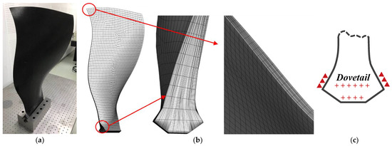
Figure 1.
Photo of composite fan blade and FE model: (a) Composite fan blade; (b) FE model; (c) Boundary conditions.

Table 1.
Material properties.
By using this FE model, the first five natural frequencies, mode shapes and modal strains are calculated. The “combined” modal strain under the condition of different mode shape combinations (with certain tip displacement ratio between different modes) are also calculated.
3. Vibration Test
The vibration test system for composite blades is shown in Figure 2. The whole system consists of a clamping system, an excitation system and a measurement system. The clamping system consists of a fixture and a base. The MFC excitation system consists of a signal generator, three MFC patches and two high-voltage power amplifiers, which can generate complex excitation forces with different frequencies. The measurement system uses a non-contact measurement scanning laser vibrometer to measure the response of the measuring points on the composite blade.
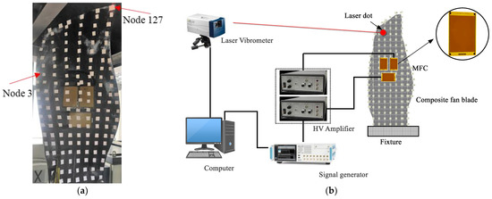
Figure 2.
Schematics of the vibration test system: (a) Photo of the fan blade with 3 MFC actuators; (b) Test system.
In this paper, three M8557-P1 MFC actuators produced by the Smart Material Company are used. The dimensions and material properties of M8557-P1 MFC actuators can be found in Ref. [7]. The selection of the position of the MFC is based on the modal analysis results. The modal strain in the MFC polarization direction of a certain mode at the position of the MFC on the blade must be sufficiently large, so that the MFC can excite this mode effectively. The polarization direction of MFC Nos. 1 and 2 piezoelectric fibers is spanwise, and the polarization direction of MFC No. 3 piezoelectric fibers is chordwise. In order to study the blade response characteristics, measuring points with relatively large responses are selected according to the mode shape contour, as shown in Figure 2.
High voltage power amplifiers and signal generators provide open loop control (no feedback) voltage changes applied to the MFC actuator. The amplifier is a Trek PA05029 constant voltage amplifier. The voltage output range is −500 V~+1500 V, and the voltage is amplified by 200 v/v (external voltage source), which can excite P1 type MFC actuators. The measurement system can monitor the vibration of the blade. The measurement is performed by a Polytech PSV-500-H multi-point scanning vibrometer. According to the geometry of the composite blade, a quadrilateral node scanning grid is generated (as shown in Figure 2), and the vibration speed of each node can be measured separately. The point-by-point scanning method can obtain the response amplitude and phase of each point in the frequency domain. For signal synchronization, the voltage signal output from the signal generator is used as the trigger signal of the PSV-500-H vibrometer. The PC receives data from the measurement system and then records, saves and analyzes the measurement data.
The signal generator can output sine, square, and noise waveforms. Different kinds of excitation signal, fast sine sweep, white noise, and pulse excitation signals are input to a single MFC actuator to excite first 5 modes of the blade, and the response of the blade is compared to find out which kind of signal can excite the blade most efficiently. Based on these results, the response of the blade under the instantaneous excitation of three MFC actuators with different combinations of several natural frequencies are measured.
4. Discussion
4.1. Natural Frequency and Mode Shape
In this study, MFC actuators are used to excite the fan blade and the blade response under different excitation signals, and the results are compared to pining test results. The velocity response of the Node127 (on the tip of the leading edge) is shown in Figure 3. The natural frequency results agree with each other very well. The mass and stiffness of the MFC actuators and wires has a negligible effect on the natural frequency of the blade. From Figure 3b–d, it can be seen that fast sine sweep and pulse excitation have better signal-to-noise ratio than white noise excitation. The pining test requires many repetitions to determine the pining and measuring location to obtain good results. The MFC excitation method entails simple and convenient operation, good repeatability, and high signal-to-noise ratio.
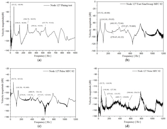
Figure 3.
Frequency domain response of Node 127 under four typical types of excitation signal: (a) Pining test; (b) Fast sine sweep; (c) Pulse excitation; (d) White noise excitation.
The first five modes’ natural frequency and mode shape comparison between the test results and the finite element simulation results is shown in Table 2 and Figure 4. Table 2 shows that the difference of the natural frequencies of the first five modes of the composite wide-chord blade obtained by simulation and experiment are less than 4%. We used a Modal Assurance Criterions (MAC) [33] to compare the test results with the FEM results as shown in Figure 5. From the MAC results, we can see that the mode shape of the first four modes predicted by using FEM methods agree well with the test results. However, the mode shape of the fifth mode predicted by the FEM method deviated from the test results, as shown in the zone marked by red box (Figure 4), which indicates that the high-fidelity FE model can predict the natural frequency and mode shape very well but still need to be improved in some local stiffness predictions. The reason is that some local thickness of the fan blade deviated from the design value. Figure 6 shows the first principle modal strain contour of the five modes on the blade pressure side and suction side, respectively. This provides a baseline for the comparison of modal strain between single mode and multi-mode vibration.

Table 2.
Test frequency and FE simulation frequency.
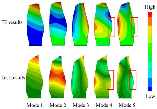
Figure 4.
The first five mode shapes.
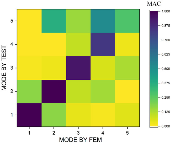
Figure 5.
Modal Assurance Criteria (MAC) for the first five modes.
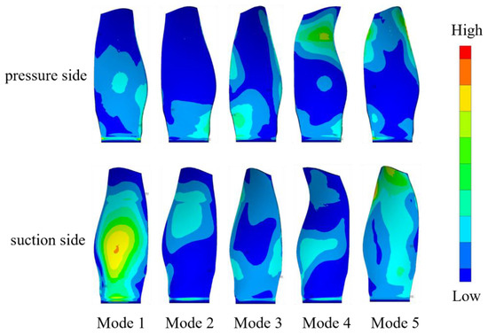
Figure 6.
Modal strain contour.
4.2. Blade Response Excited by Single MFC
Figure 7 plots the frequency-domain response of the measuring points of interest on the composite blade excited by different MFC actuators. The excitation signal is a fast linear sinusoidal frequency sweep signal. When observing the first five natural frequencies obtained from node 127 and node 3 (as shown in Figure 2) and comparing the amplitude-frequency response curves excited by three different MFCs, it is very clear that the same mode excited by different MFCs has different responses. Take mode 3 as an example. Mode 3 is the first torsion mode, at the tip of the leading edge (Node 127); the peak value of mode 3 excited by MFC 02 is small, and on the amplitude-frequency response curve, the peak is not obvious. The response value of the blade is closely related to the position and the polarization direction of the MFC fiber. Figure 8a,b shows the spanwise and chordwise modal strain contour of mode 3. The modal strain in the spanwise direction of mode 3 covered by MFC No. 2 is very small, so it cannot excite mode 3 effectively. The blade response excited by MFC 03 is slightly larger than that excited by of MFC 01. This is because the spanwise modal strain (around MFC 01) is smaller than the chordwise modal strain in the area of MFC 03 under the condition of the same tip deflection.
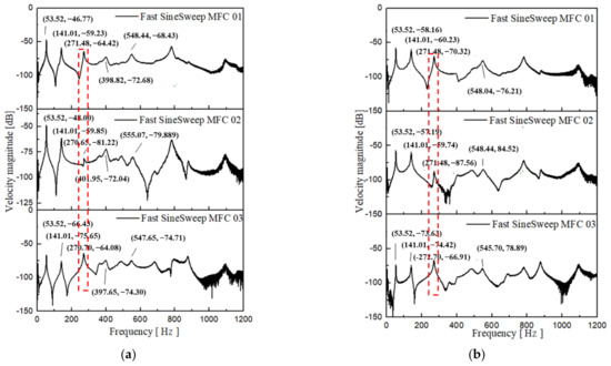
Figure 7.
MFC fast sine sweep signal excitation: (a) Node 127; (b) Node 3.
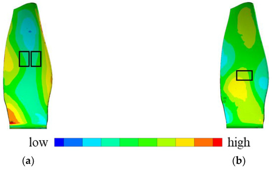
Figure 8.
Modal strain of mode 3: (a) Spanwise modal strain; (b) Chordwise modal strain.
From the amplitude-frequency response curve of different measuring points excited by different MFC actuators, it can be found that under MFC 01 excitation, the blade vibration is mainly low-order bending and first-order torsion modes. Under MFC 02 excitation, the blade vibration is low-order bending mode. Under the excitation of MFC 03, the first-order torsion mode is obvious. Therefore, when the position of the polarization direction of the MFC fiber is along the spanwise direction of the blade, the vibration of the blade is mainly low-order bending. If we want to excite the torsional mode, we need to arrange the MFC actuator in the position where modal strain is high enough in the torsional mode. For wide-chord composite fan blades, the MFC actuator can be placed close to the blade’s half-blade height, which can excite the first five order modes of the blade.
On the other hand, the selection of the measuring point is very important. For low-order bending modes (mode 1 and mode 2), the measuring point on the blade tip can achieve the largest response value; when the measuring point is close to the trailing edge of the half-blade height, the response of the low-order bending mode is small, but the response of the high-order bending mode and torsion mode is large.
4.3. Blade Response Excited by Two MFCs with Same Frequency
This paper considers the use of two MFC actuators with the same frequency to stimulate the blades and studies the dynamic response characteristics of the blade excited by different combinations of MFC actuators. The signal generator sends a fast sinusoidal sweep signal to the high voltage power amplifier, and two MFC actuators are connected to the output of the amplifier. Three combinations are tested in this paper, which are MFC 01 + 02, MFC 01 + 03 and MFC 02 + 03.
The response of the blade excited by a single MFC actuator and two MFC actuators with same frequency is measured. The amplitude-frequency response curves of Node 127 at the blade tip is shown in Figure 9. Table 3 compares the response amplitude of Node 127 under the condition of different excitation combinations. The response amplitude is normalized according to different excitation combinations. From Table 3, the difference of response amplitudes of Node 127 excited by single MFC 01 and MFC 02 are small for bending modes (mode 1, mode 2 and mode 4) and large for torsion and stripe modes (mode 3 and mode 5). For mode 1, 2 and 4, the response amplitude of the blade excited by the combination of MFC 01 and 02 is significantly higher than that excited by single MFC 01 or MFC 02, which is 1.66, 1.81 and 1.83 times the amplitude excited by the MFC 01 alone. The response of node 127 excited by two MFC actuators is not equal to the sum of the response excited by the two single MFC actuators. For mode 3 and mode 5, the amplitude excited by MFC 01 alone is significantly larger than that excited by MFC 02 (55 times, 3.74 times). For mode 3 and mode 5, the response amplitude excited by MFC 01 and MFC 02 are much smaller than that excited by MFC 01 and much larger than that excited by MFC 02. The reason is the difference of the phase angle in the area of MFC 01 and 02 in mode 3 and mode 5. MFC 02 cannot excite mode 3 and mode 5 effectively.
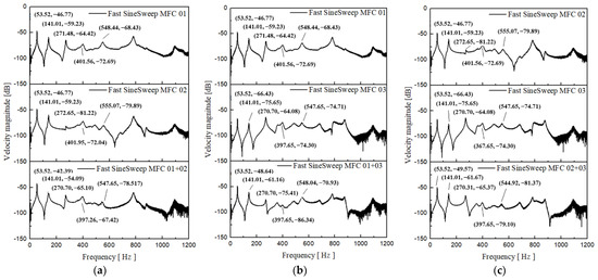
Figure 9.
Frequency domain response of Node 127 under single and combined MFC excitation: (a) MFC 01 + 02; (b) MFC 01 + 03; (c) MFC 02 + 03.

Table 3.
The response amplitude of Node 127 under MFC superimposed and individual excitation.
In the case of MFC 01 and 03 combined excitation, the first five mode shapes can be excited. However, the response amplitude of the blade is lower than that excited by MFC 01 and higher than that excited by MFC 03. Especially for mode 3, the ratio of the response amplitude is only 0.04, which means the phase angle difference of the responses where MFC01 and 03 are pasted is not zero. A similar situation appears in the combination of MFC 02 and MFC 03 excitation.
For the two MFC actuator combined excitations with same frequency, the superimposed response amplitude is not equal to the sum of the response amplitude excited by the single MFC actuator. The enhancement effect is related to the modal strain in the fiber polarization direction and modal order, the relative magnitude of the blade excited by single MFC actuator and the phase angle difference between the areas where the MFC actuators are pasted. When the polarization directions of the fibers in the two MFC actuators are the same, the superimposed amplitude of the bending mode is increased compared to each individual MFC excitation; the superposed amplitude of the torsional mode is between the amplitude excited by the two single MFC actuators. When the polarization directions of the two MFCs are different, the amplitude of the superimposed amplitude is also between the amplitude excited by the two single MFC actuators. From the above analysis, it can be seen that the response excited by the combination of MFC actuators is not necessarily better than that excited by one MFC actuator. If one MFC actuator cannot effectively excite all the modes, multiple MFCs can be used, but the location and direction of the MFC should be preferentially selected.
Where, is the response amplitude excited by MFC i and j, normalized by the response amplitude excited by MFC k. is the response amplitude excited by MFC i, and is normalized by the response amplitude excited by MFC j.
4.4. Blade Response Excited by Two MFCs with Different Frequencies
The fan blade is in the front of the engine and will be subjected to mechanical or aerodynamic excitation; these complex excitations come from unsteady flow (distorted flow, turbulence and vortex ingestion, etc.) and mechanical induced vibration (rotor vibration, bird or ice impact, blade tip rubbing, etc.). The mechanically and aerodynamically induced excitation is very different in frequency domain, and these excitations may be instantaneously imposed on the fan blade. It is necessary to study the mode coupling problem in fan blades. The multiple MFC actuators could simulate different types of excitations, and we can use this to study the vibration characteristics of fan blades.
On the other hand, the using of multiple MFC actuators in blade testing will be a useful method in the validation and calibration of the blade tip timing (BTT) system. BTT systems are becoming more and more popular in the vibration measurement of rotating blades. However, the validation and calibration of the BTT system are very complicated. By using the multiple MFC actuators, we can generate complicated excitation sources with different frequencies and amplitudes, and they can help us in validation of the BTT system.
Very few studies have been conducted in this area. In this paper, the response of the blade under the instantaneous excitation of two MFC actuators with different combinations of natural frequencies is measured.
The first five mode shapes are 1st flex (1F), 2nd flex (2F), 1st torsion (1T), 3rd flex (3F) and two-stripe (2S) modes, respectively. Figure 10 shows the signal of 1F, 2F, 1T and 2S and the supposed signal of 1F + 2F, 1F + 1T, 2F + 1T and 1T + 2S. The horizontal axis is time, and the vertical axis is the magnitude of the respective excitation voltage.
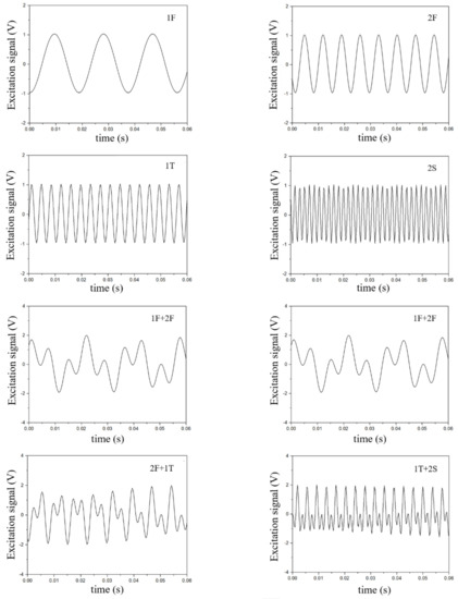
Figure 10.
Time history of single frequency signals and superposition of two frequency signals.
Figure 11a shows the response of the nine measuring points along the chordwise direction from the trailing edge (TE) to the leading edge (LE) at 50% height of the blade under the condition of different combinations of excitations with different natural frequencies. We also conducted a curve fitting to determine the relationship between superimposed response and response by single MFC excitation. Four results are shown in Figure 11: 1F + 2F, 1F + 1T, 2F + 1T and 1T + 2S.
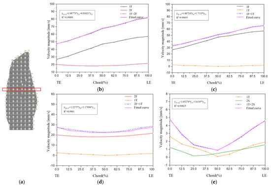
Figure 11.
The response amplitude of different frequency superposition excitations with the same voltage: (a) Position of the measuring points; (b) 1F + 2F; (c) 1F + 1T; (d) 2F + 1T; (e) 1T + 2S.
From the fitted curve, the response excited by the MFC actuator with two different natural frequencies is a linear summation of the response excited by the single MFC actuator with one natural frequency. However, the weight coefficients of the response excited by a single natural frequency is not equal to 1.0. These coefficients are related to the modal order. From Figure 11b, it can be found that the weight coefficient of 1F is greater than 1.0, the weight coefficient of 2F is less than 1.0, and the sum of the two weight coefficients is 1.998, which is slightly less than 2. This indicates that 2F can slightly enhance the 1F response, and 1F slightly decreases the 2F response. If the amplitudes of the blade responses under the single excitation of 1F and 2F before the superposition are the same, the results of the fitted curve show that the amplitude of the superposed blade response is slightly smaller than the superposition of the two separate frequency signals. However, the assumption that the 1F and 2F separate excitation blades have the same response amplitude may not occur in practice, because the energy of the 1F excitation is larger than that of the excitation of other orders. Therefore, in the 1F and 2F combined resonant excitation, the blade amplitude under the 1F excitation plays a dominant role. Similarly, under the condition of 1F + 1T, 2F + 1T and 1T + 2S combined resonant excitations, the weight coefficients of 1F, 2F and 1T are greater than 1. The response amplitudes of combined resonant excitation are greater than the linear superposition of the resonant excitation response amplitudes. The weight coefficients depend on the modal order.
Figure 12 shows the superimposed first principle modal strain contour according to the ratio listed in Table 3. It can be seen from Figure 12 that the strain contour is changed compared to that shown in Figure 5. In the case of 1F + 2F, the strain contour is very similar to that of 1F, which means that mode 1 plays the dominant role in the mode coupling. A similar phenomenon appears in the case of 1F + 1T. On the other hand, the location of the maximum strain may also change (compared to the dominant mode), which means that the high cycle fatigue weak-link location may change under complex excitation conditions. The fan blade in this paper is made of composite materials; more detailed analysis and evaluation need to be performed to determine the effect of mode coupling on the vibration and fatigue.
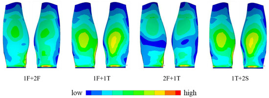
Figure 12.
The superimposed modal strain contour.
5. Conclusions
In this study, an MFC excitation system is established. Three MFC actuators are arranged at three different positions of a composite wide-chord fan blade, and a vibration test is performed. The natural frequency and mode shape of the blade are compared with simulated values. The response of composite fan blades under MFC excitation is as follows:
- (1)
- The first five natural frequencies and modal shapes of the composite fan blades obtained by FE simulation and modal testing using the MFC excitation method match very well, indicating that the MFC excitation method used in this paper and the high-fidelity finite element model have very good accuracy.
- (2)
- When using MFC to measure composite fan blade mode shape and natural frequency, the polarization direction and the paste area of the MFC must be carefully selected based on the FE results.
- (3)
- Blade response excited by two MFCs with same frequency is dependent on the position and direction of the MFC. The superimposed response amplitude of the bending mode is increased compared to that excited by a single MFC, and the superimposed response amplitude of the torsion mode is between the two response amplitudes excited by single MFC.
- (4)
- Blade response excited by two MFCs with different natural frequencies is dominated by the mode with a larger response excited by single MFC.
Author Contributions
Y.C.: formal analysis, data curation, and writing; L.J.: review and editing; X.T.: investigation and visualization; D.H.: writing and review; J.Z.: review and editing. All authors have read and agreed to the published version of the manuscript.
Funding
This work was supported by Special Fund for National Science and Technology Major Project (2017-II-0007-0021), China.
Data Availability Statement
All data supporting this study are available in the article.
Acknowledgments
The authors would like to acknowledge financial support from the National Science and Technology Major Project.
Conflicts of Interest
The authors declare no conflict of interest.
References
- Amoo, L.M. On the design and structural analysis of jet engine fan blade structures. Prog. Aerosp. Sci. 2013, 60, 1–11. [Google Scholar] [CrossRef]
- Chinta, V.S.; Reddy, P.R.; Prasad, K.E. The effect of stacking sequence on the tensile properties of jute fibre reinforced hybrid composite material for axial flow fan blades: An experimental and finite element investigation. Mater. Today Proc. 2022, 59, 747–755. [Google Scholar] [CrossRef]
- Jin, H.; Liu, H.; Ma, L.; Gu, H.; Wang, J. Structural Response Analysis of Composite Fiber Blade of Small Wind Power Generator Turbine Blades. In Proceedings of the 2022 IEEE International Conference on Electrical Engineering, Big Data and Algorithms (EEBDA), Changchun, China, 25–27 February 2022; pp. 233–238. [Google Scholar]
- Morozov, A.V.; Kravchenko, I.F.; Torba, Y.I.; Lvov, G.I. Dynamics Numerical Prediction for Composite Wide-Chord Fan Blade. In Proceedings of the 2021 IEEE 2nd KhPI Week on Advanced Technology (KhPIWeek), Kharkiv, Ukraine, 13–17 September 2021; pp. 686–690. [Google Scholar]
- Sun, Y.; Zhang, Y.; Zhou, Y.; Zhang, H.; Zeng, H.; Yang, K. Evaluating Impact Damage of Flat Composite Plate for Surrogate Bird-Strike Testing of Aeroengine Fan Blade. J. Compos. Sci. 2021, 5, 171. [Google Scholar] [CrossRef]
- Jadhav, P. Design Methodologies for Composite Structures in Aircraft Engines. In Advanced Composites in Aerospace Engineering Applications; Springer: Cham, Switzerland, 2022; pp. 93–108. [Google Scholar]
- Federal Aviation Administration, FAR-33 Airworthiness Standards: Aircraft Engines; Federal Aviation: Washington, DC, USA, 2016.
- Wang, Z.; Chen, Y.; Ou, Y.; Wang, A. Vibration characteristics of titanium wide-chord fan blade. J. Aerosp. Power 2018, 33, 2593–2601. (In Chinese) [Google Scholar] [CrossRef]
- Kou, H. Research on Multi-Point Vibration Characteristics and Fatigue of Civil Aviation Engine High-Pressure Compressor Blade. Ph.D. Thesis, Tian Jin University, Tianjin, China, 2017. (In Chinese). [Google Scholar]
- Teter, A.; Gawryluk, J. Experimental modal analysis of a rotor with active composite blades. Compos. Struct. 2016, 153, 451–467. [Google Scholar] [CrossRef]
- Yang, S.; Allen, M.S. Output-only Modal Analysis using Continuous-Scan Laser Doppler Vibrometry and application to a 20 kW wind turbine. Mech. Syst. Signal Process. 2012, 31, 228–245. [Google Scholar] [CrossRef] [Green Version]
- Heylen, W. Modal Analysis Theory and Testing, 2nd ed.; Departement Werktuigkunde Press: Leuven, Belgium, 1998. [Google Scholar]
- Williams, R.B.; Park, G.; Inman, D.J.; Wilkie, W.K. An overview of composite actuators with piezoceramic fibers. Proc. IMAC XX 2002, 47, 421–427. [Google Scholar]
- Bent, A.A. Active Fiber Composites for Structural Actuation; Massachusetts Institute of Technology: Cambridge, MA, USA, 1997. [Google Scholar]
- Wilkie, W.K.; Bryant, R.G.; High, J.W.; Fox, R.L.; Hellbaum, R.F.; Jalink, A., Jr.; Little, B.D.; Mirick, P.H. Low-Cost Piezocomposite Actuator for Structural Control Applications. In Smart Structures and Materials 2000: Industrial and Commercial Applications of Smart Structures Technologies; International Society for Optics and Photonics: Bellingham, WA, USA, 2000; Volume 3991, pp. 323–335. [Google Scholar]
- Jemai, A.; Najar, F.; Chafra, M.; Ounaies, Z. Mathematical modeling of an active-fiber composite energy harvester with interdigitated electrodes. Shock. Vib. 2014, 2014, 971597. [Google Scholar] [CrossRef]
- Dong, Z.; Faria, C.; Hromčík, M.; Pluymers, B.; Šebek, M.; Desmet, W. Equivalent force modeling of macro fiber composite actuators integrated into non-homogeneous composite plates for dynamic applications. Smart Mater. Struct. 2017, 26, 095040. [Google Scholar] [CrossRef]
- Roosevel, A.F.D. Finite element modeling of piezoelectric structures. AIAA J. 1993, 31, 930–937. [Google Scholar]
- Guennam, A.E.; Luccioni, B.M. Piezoelectric shell FE for the static and dynamic analysis of piezoelectric fibre composite laminates. Smart Mater. Struct. 2009, 18, 095044. [Google Scholar] [CrossRef]
- Zhang, S.Q.; Li, Y.X.; Schmidt, R. Modeling and simulation of macro-fiber composite layered smart structures. Compos. Struct. 2015, 126, 89–100. [Google Scholar] [CrossRef]
- Prasath, S.S.; Arockiarajan, A. Influence of bonding layer on effective electromechanical properties of macro-fiber composites (MFCs). Smart Mater. Struct. 2014, 23, 095046. [Google Scholar] [CrossRef]
- Fagerholt, E.; Dørum, C.; Børvik, T.; Laukli, H.I.; Hopperstad, O.S. Experimental and numerical investigation of fracture in a cast aluminium alloy. Int. J. Solids Struct. 2010, 47, 3352–3365. [Google Scholar] [CrossRef] [Green Version]
- Smart Material MFC Overview. 2017. Available online: http://www.smart-material.com/MFC-product-main.html (accessed on 8 March 2021).
- Belz, J.; May, M.; Siemann, J.; Seume, J.R.; Voigt, C.; Böhmer, H.; Grüber, B. Excited Blade Vibration for Aeroelastic Investigations of a Rotating Blisk Using Piezo-Electric Macro Fiber Composites. In Proceedings of the ASME Turbo Expo 2013: Turbine Technical Conference and Exposition, San Antonio, TX, USA, 3–7 June 2013; American Society of Mechanical Engineers: New York, NY, USA, 2013. V07BT33A011. [Google Scholar]
- Deraemaeker, A.; Nasser, H. Numerical evaluation of the equivalent properties of Macro Fiber Composite (MFC) transducers using periodic homogenization. Int. J. Solids Struct. 2010, 47, 3272–3285. [Google Scholar] [CrossRef] [Green Version]
- Steiger, K.; Mokrý, P. Finite element analysis of the macro fiber composite actuator: Macroscopic elastic and piezoelectric properties and active control thereof by means of negative capacitance shunt circuit. Smart Mater. Struct. 2015, 24, 025026. [Google Scholar] [CrossRef]
- Di Rito, G.; Chiarelli, M.R.; Luciano, B. Dynamic Modelling and Experimental Characterization of a Self-Powered Structural Health-Monitoring System with MFC Piezoelectric Patches. Sensors 2020, 20, 950. [Google Scholar] [CrossRef] [Green Version]
- Baghaee, M.; Farrokhabadi, A.; Jafari-Talookolaei, R.A. A solution method based on Lagrange multipliers and Legendre polynomial series for free vibration analysis of laminated plates sandwiched by two MFC layers. J. Sound Vib. 2019, 447, 42–60. [Google Scholar] [CrossRef]
- Wang, X.; Zhou, W.; Zhang, Z.; Jiang, J.; Wu, Z. Theoretical and experimental investigations on modified LQ terminal control scheme of piezo-actuated compliant structures in finite time. J. Sound Vib. 2021, 491, 115762. [Google Scholar] [CrossRef]
- Baghaee, M.; Farrokhabadi, A.; Jafari-Talookolaei, R.A. Modeling, analysis, and control of MFC sandwiched laminate panel flutter with general layups and arbitrary boundary conditions. Compos. Struct. 2019, 223, 110940. [Google Scholar] [CrossRef]
- Chu, W.L.; Lin, C.J.; Li, M.J. Active multimode vibration control of a smart structure using macro fiber composite actuators based on ANFIS. J. Low Freq. Noise Vib. Act. Control 2020, 39, 1187–1203. [Google Scholar] [CrossRef]
- Zhang, J.; Tu, J.; Li, Z.; Gao, K.; Xie, H. Modeling on actuation behavior of Macro-Fiber Composite laminated structures based on sinusoidal shear deformation theory. Appl. Sci. 2019, 9, 2893. [Google Scholar] [CrossRef] [Green Version]
- Pastor, M.; Binda, M.; Harčarik, T. Modal assurance criterion. Procedia Eng. 2012, 48, 543–548. [Google Scholar] [CrossRef]
Publisher’s Note: MDPI stays neutral with regard to jurisdictional claims in published maps and institutional affiliations. |
© 2022 by the authors. Licensee MDPI, Basel, Switzerland. This article is an open access article distributed under the terms and conditions of the Creative Commons Attribution (CC BY) license (https://creativecommons.org/licenses/by/4.0/).