Article

Experimental Study of Measuring the Wrinkle of Solar Sails

College of Aerospace Science and Engineering, National University of Defense Technology, 109 Deya Road, Kaifu District, Changsha 410073, China
*
Author to whom correspondence should be addressed.
Aerospace 2022, 9(6), 289; https://doi.org/10.3390/aerospace9060289
Submission received: 1 April 2022 / Revised: 16 May 2022 / Accepted: 23 May 2022 / Published: 26 May 2022

Abstract

:
Conducting a wrinkling analysis for a membrane structure of complex boundary conditions is quite difficult. This paper develops a numerical calculation method for completing a wrinkling analysis of a square membrane structure and a trapezoidal membrane structure with static corner forces. Furthermore, an experimental system for measuring the wrinkle is designed and established to verify the correctness of the method. The difference between simulation analysis results and experimental results is quite small for small corner forces, which means the method used for the wrinkling analysis under small loads is effective.

1. Introduction

1.1. Application of Solar Sails in Aerospace

The solar sail spacecraft was proposed in the 1930s. As a new type of spacecraft independent of working substance, it attracted the attention of many countries as soon as it appeared. Cosmos 1 is the first solar sail spacecraft planned to launch [1]. It was developed by the Planetary Society but failed to enter orbit due to the failure of the rocket. After a long period of research and improvement, the IKAROS project, developed by the Japan Aerospace Exploration Agency (JAXA), was successfully launched in 2010 [2]. IKAROS had successfully verified the solar sail spinning deployment technology and orbit attitude control technology. Subsequently, the United States launched the NanoSail-D2, Lightsail-1, and Lightsail-2 earth orbiting solar sail spacecraft in 2011, 2015, and 2019, respectively [3,4,5]. The University of Surrey also successfully carried out a solar sail mission in 2017 and launched a 1 m inflatable mast and 10 m2 drag sails in orbit [6,7]. The Deutsches Zentrum für Luft-und Raumfahrt (DLR) in Germany carried out the development of the Gossamer-1 solar sail spacecraft, but the project was terminated [8,9]. At present, the Near Earth (NEA) Asteroid Scout mission under the joint cooperation of NASA MSFC and the Jet Propulsion Laboratory (JPL) is in the development stage, and it plans to utilize an 86 m2 square solar sail to propel a 6U CubeSat bus on a reconnaissance flyby trajectory of a 100 m asteroid [10]. Furthermore, JAXA also proposed a new generation of solar sail spacecraft named “OKEANOS”, aiming at exploring a Jupiter Trojan asteroid [11]. There still are many unsolved problems for solar sail spacecraft, but its great advantage of being independent of working substance will make it play an important role in asteroid exploration [12], interstellar travel [13], and so on.

1.2. Wrinkling Analysis

The solar sail structure belongs to membrane structure. At present, the theoretical research of membrane wrinkling is mainly based on two theories: the tension field theory and the stability theory. The tension field theory was first proposed by Wagner and used in the buckling analysis of metal sheets [14]. The tension field theory has been developed for many years. Many scholars have proposed many improved methods for different problems, such as a variable Poisson’s ratio method [15], a condensation model reduction method [16], and a relaxed strain energy density method [17]. The tension field theory can accurately obtain the direction and distribution area of wrinkles, but it fails to obtain information on the out-of-plane deformations, such as the amplitude. Besides, it is only applicable to the membrane structure with simple boundary conditions. Therefore, the tension field theory is not particularly applicable to a membrane structure with complex boundary conditions, such as solar sails. The stability theory holds that membrane wrinkling is a local buckling phenomenon of a membrane, and it was also first proposed by Wagner. Based on the stability theory, the complete shape of wrinkles can be obtained, including direction, distribution area, shape, and quantity. However, the bending stiffness of the membrane is very small and the buckling problem under loads has obvious nonlinear characteristics, and so the computation is very difficult. Nonlinear buckling analysis is a widely used numerical calculation method, at present. Many scholars have also proposed some improved methods, such as the modal theory method [18]. There are many studies about wrinkling analysis for different shapes of membranes, such as a rectangular membrane [19], a square membrane [20,21], a circular membrane [22], and a triangular membrane [20,23]. For solar sails, many scholars have also carried out specific analyses and research. For example, Deng carried out detailed research on the wrinkling modeling of a solar sail subjected to solar radiation pressure [24], and Tommo conducted an experimental study on the wrinkling analysis for small solar sails [25].

2. Model and Method

2.1. Solar Sail Model

In this paper, two kinds of solar sail structures are studied: one is a quadrilateral solar sail and the other is a hexagonal solar sail, as shown in Figure 1. The sail is fixed to the beam by the tack line. In the prevention of the edge tearing of the sail, multi-layer hemming is adopted, and in order to facilitate the connection between the tack line and the sail, the metal snap ring structure is added, as shown in Figure 1d. The area of the solar sail is generally more than 100 m2. Limited to the experimental conditions, this paper will use a much smaller solar sail structure as the research object. For the regular quadrilateral solar sail shown in Figure 1a, its side length is 1000 mm. For the regular hexagonal solar sail shown in Figure 1b, its 1/6 solar sail is an isosceles trapezoidal structure with a length of 26.6 mm for AB, a length of 1000 mm for CD, and a height of 853.4 mm.

2.2. Nonlinear Buckling Analysis Method

Wrinkling analysis conducted through nonlinear buckling analysis is the only way to obtain the configuration parameters (wavelength and amplitude). The numerical calculation method of the wrinkling characteristics of membrane structures is essentially a nonlinear finite element method to solve the static problems. The purpose is to solve the critical load and the wrinkling shape after buckling when the structure transitions from stable equilibrium to unstable equilibrium, as well as the relationship between the wrinkling shape after buckling and the load.
The nonlinear finite element equation of the static equilibrium problem based on total Lagrange (T.L.) formulation can be expressed as [26]:
( K t L s + K t L 1 + K t N L ) u = Q t + Δ t     F t ,
where u is the node displacement increment vector, Q t + Δ t is the node load vector at the time of t + Δ t , the left superscript t represents the current time, F t is he external force vector at the time of t , t K t L s is the element stiffness matrix in the case of small displacement, K t L d is the initial displacement matrix caused by the initial displacement, and K t N L is the initial stress matrix caused by the initial stress. K t L s , K t L d , K t N L , and F t can be expressed as:
{ K t L s = e V t B L 0 T D t B L 0 d V K t L d = e V ( B t L 0 T D t B L 1 + B t L 1 T D t B L 0 + B t L 1 T D t B L 1 ) d V K t N L = e V t B N L T S t B t N L d V F t = e V t B L T S ¯ t d V
where D is the material constitutive matrix; B t L 0 and B t L 1 are the transformation matrix between the terms ( u i , j + u j , i ) / 2 and ( u t k , i u k , j + u t k , j u k , i ) / 2 in the linear strain with the displacement, respectively; B t N L is the transformation matrix of the nonlinear strain and displacement; and S t and S ¯ t are the Piola–Kirchhoff stress matrix and vectors of the second kind, respectively. The elements of the above matrix and vectors are determined as corresponding to the configuration at the time of t relative to the reference configuration.
For the problem of structural stability, the load can be expressed as:
Q = p Q ¯ ,
where Q ¯ is the load mode and p is the load amplitude. Determining the critical load of the structure finds the critical value when the tangent stiffness matrix of the geometric nonlinear equation of the structure becomes singular. For the T.L. format, it solves the following eigenvalue problem:
K τ ϕ = 0 ,
where K τ = K τ L s + K τ L d + K τ N L and the left superscript τ represents the time of the critical load p c r .
When using nonlinear buckling analysis, the stiffness matrix of the structure is a nonlinear function of the load amplitude p and displacement vector u , which represents a nonlinear eigenvalue problem. By solving the linear eigenvalue equation, the wrinkling shape of the membrane after buckling can be obtained.
We trace along the load–balance path to determine the adjacent interval of the solution. For the convergent solution u t + Δ t and S t + Δ t corresponding to each incremental step, we can calculate K t + Δ t . If there exists the following inequality:
det ( K t ) > 0   &   det ( K t + Δ t ) < 0 ,
then it means that at some time τ in the time interval ( t , t + Δ t ) , there is
det ( K τ ) = 0 .
That is, K τ is singular. The point corresponding to the time τ on the equilibrium path is the critical point of equilibrium transition from stability to instability, and the load corresponding to that time is the critical load of buckling.
At the end of each incremental step, in order to prepare for the iterative calculation of the next step, it is usually necessary to carry out triangular decomposition for K , as follows:
K t + Δ t   =   LDL T
where L T is the upper triangular matrix with a diagonal element of 1 and D is a diagonal matrix with the diagonal elements d i i ( i = 1 , 2 , , n ) . Therefore
det ( K t + Δ t ) = det ( D ) = i = 1 n d i i .
Assuming that all d i i from K t are positive and only one d i i from K t + Δ t is negative, it will be expressed as a linear interpolation of K t and K t + Δ t , as follows:
K τ = K t + t c r t Δ t ( K t + Δ t K t ) .
By substituting the above equation into characteristic Equation (6), the characteristic equation of nonlinear buckling analysis can be expressed as:
[ K t + λ ( K t + Δ t K t ) ] ϕ = 0 ,
where λ = ( t c r t ) / Δ t . By solving Equation (10), a series of eigenvalues λ i and corresponding characteristic displacement modes ϕ i can be obtained. At the same time, there are multiple eigenvalues and characteristic displacement modes that correspond to t c r , which is the result of buckling. If t represents the load level, the corresponding load amplitude is the critical value p c r of the nonlinear stability of the structure. Equation (10) is solved by the arc length method in ABAQUS.
There are five steps in wrinkling analysis using the nonlinear buckling analysis method:
  • Establish the finite element model. In the simulation analysis software, a shell element is usually applied to simulate the membrane element.
  • Introduce the prestress. Although the shell element has a certain out-of-plane stiffness, due to small thickness of the membrane, the out-of-plane stiffness is very small, and so it is necessary to introduce the prestress to improve the out-of-plane stiffness to meet the requirements of the nonlinear buckling analysis.
  • Introduce the initial imperfection. The purpose of introducing an initial imperfection is to solve the problem of the singularity of the stiffness matrix in post-buckling analysis. The generation and evolution of wrinkles can be simulated after introducing an initial imperfection. It is hard to get large-scale solar sails’ buckling modes, so we propose the direct perturbation method by applying a small force to the membrane to introduce the initial imperfection. In order to achieve a good convergence, the force should be as small as possible.
  • The arc length method is adopted for the post-buckling analysis. When it does not converge, the load step parameters and the initial imperfection should be adjusted.
  • Post-processing is applied to analyze the influence of the concentrated tensile force on the wrinkles.

3. Numerical Simulation

3.1. Square Membrane

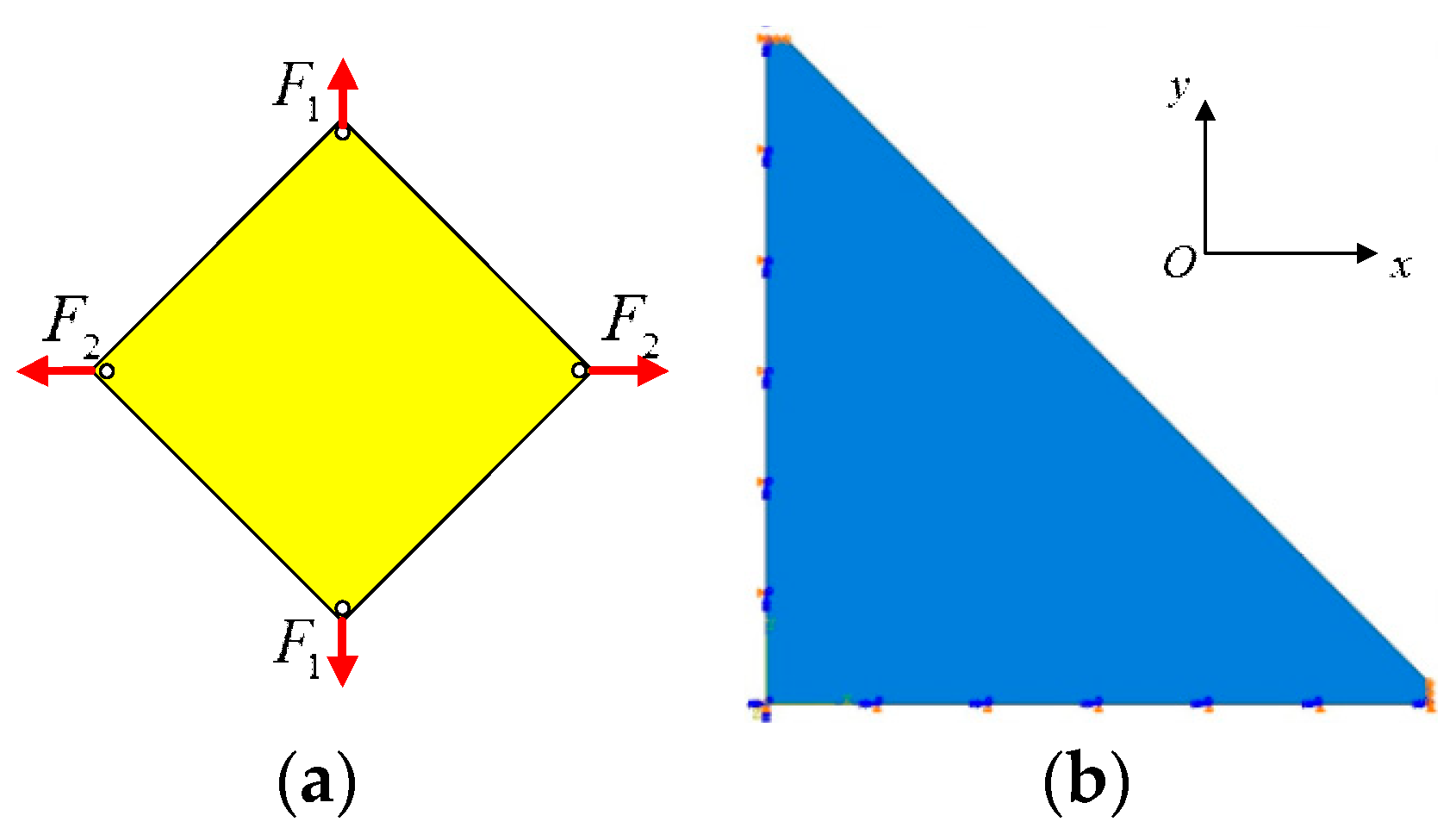
The software used for the simulation analysis is ABAQUS. According to the symmetry, a quarter of the model can be established for simulation analysis. The established finite element model is shown in Figure 2b and uses an S4R shell element. The boundary conditions are obtained according to symmetry. The translational freedom in the direction of the x -axis and the rotational freedom around the y -axis and the z -axis of the left boundary is restricted. The translational freedom in the direction of the y -axis and the rotational freedom around the x -axis and the z -axis of the bottom boundary is restricted. In order to avoid stress concentration, the corner of the membrane is treated as a 10 mm wide boundary and a uniformly distributed load is applied.
The material of the membrane is polyimide with a thickness of 50 μm. The specific material parameters are shown in Table 1.
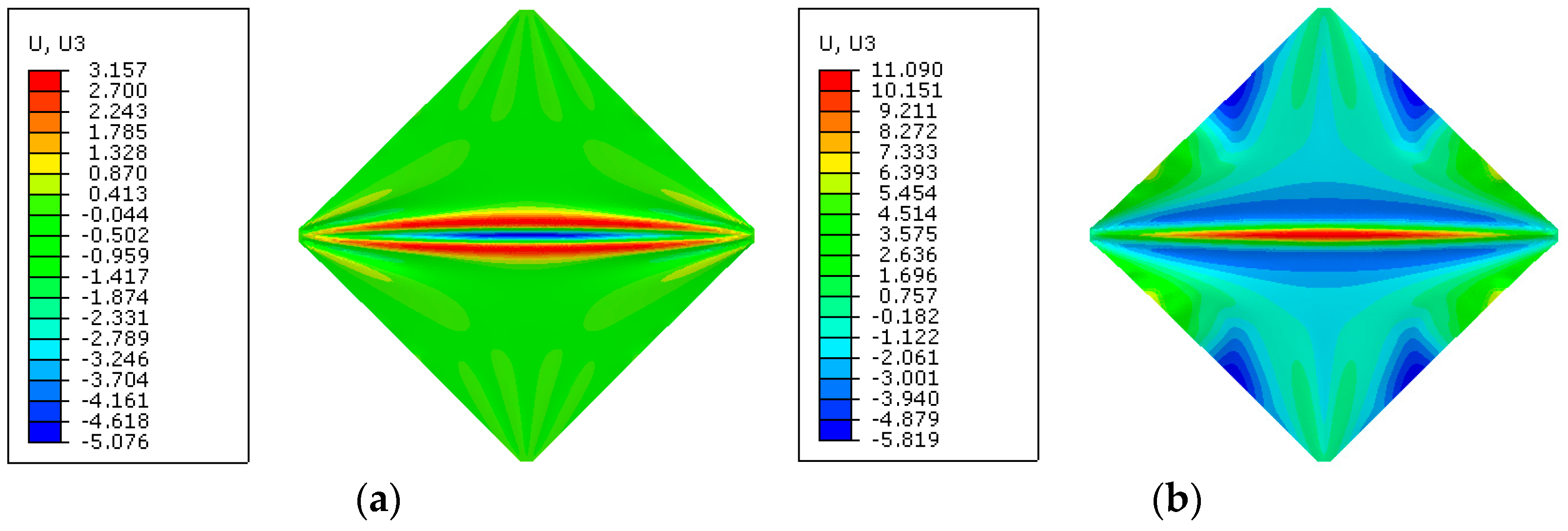
In Figure 3, a wrinkling shape obtained by simulation analysis is shown wherein F 1 = 1   N is kept unchanged and the value of F 2 is gradually increased, and where U3 represents the z-axial displacement in millimeters. This suits for all following figures, and when F 2 = 5   N , the maximum amplitude of the wrinkle is 5.08 mm, and when F 2 = 10   N , the maximum amplitude of the wrinkle is 11.5 mm.
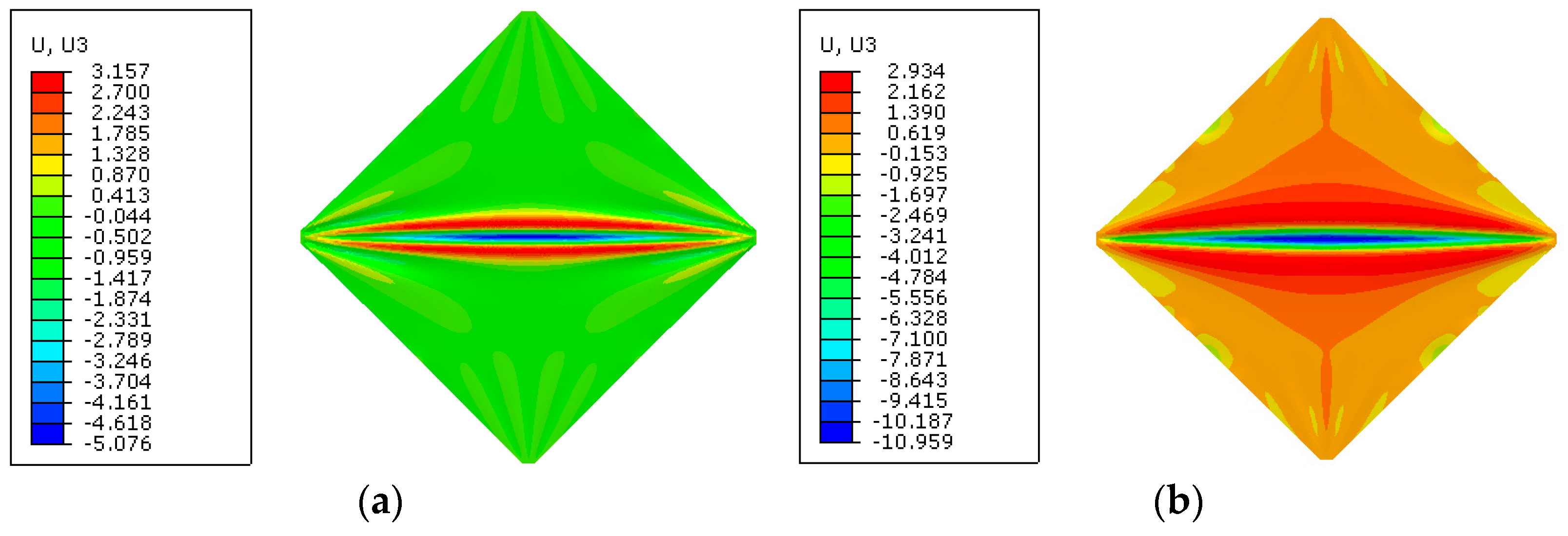
The wrinkling shape obtained by simulation analysis when F 2 / F 1 is kept unchanged is shown in Figure 4. When F 1 = 1   N and F 2 = 5   N , the maximum amplitude of the wrinkle is 5.08 mm. When F 2 = 2   N and F 2 = 10   N , the maximum amplitude of the wrinkle is 10.96 mm.

3.2. Trapezoidal Membrane

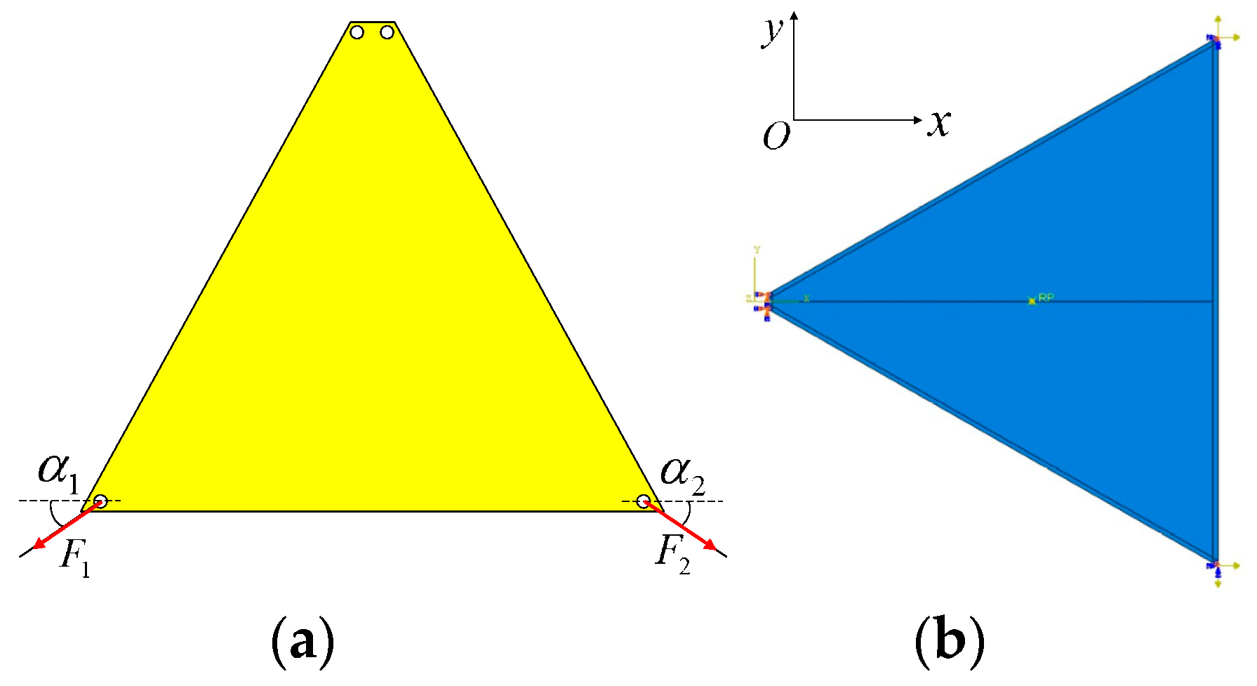
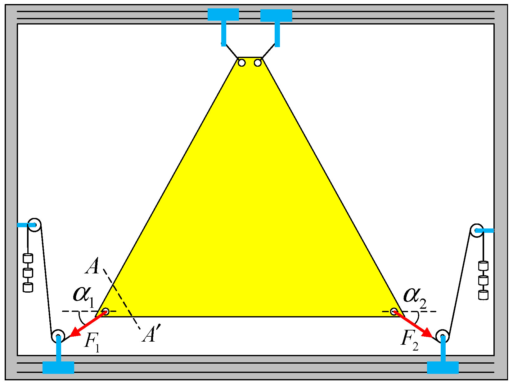
The simulation model as shown in Figure 5b is established by using an S4R shell element. The boundary condition is that the two corners of the upper edges are fixedly supported, and the two corners on the lower edges have applied force and their out-of-plane displacement is limited, as shown in Figure 5a.
Under the condition of maintaining α 1 = α 2 = 30 and gradually increasing the force to 5 N and 10 N, the wrinkle’s shape can be obtained as shown in Figure 6. The results show that when the force increases, the wrinkling shape does not change significantly, but the wrinkling amplitude changes significantly. When F 1 = F 2 = 5   N , the maximum amplitude of the wrinkle is 0.90 mm, and when F 1 = F 2 = 10   N , the maximum amplitude of the wrinkle is 1.25 mm.
Under the condition of maintaining F 1 = F 2 = 10   N and changing the force direction, the wrinkling shape obtained by simulation analysis is shown in Figure 7. The results show that when the force direction is changed from α 1 = α 2 = 30 to α 1 = α 2 = 35 , the wrinkling shape changes obviously, and the wrinkling amplitude also changes to, a certain extent, from 1.25 mm to 1.74 mm.

4. Experimental Result and Analysis

4.1. Design of the Experiment

A test system for measuring the wrinkling of a membrane structure as shown in Figure 8 is established. The test system mainly includes a test piece system, a photogrammetry system, a laser scanning system, a computer, software, and the corresponding hardware.
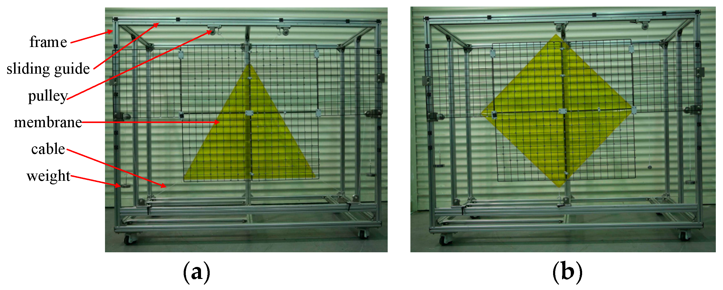
The test piece system is composed of a membrane, frame, cable, pulley, and sliding guide, as shown in Figure 9. The function of the test piece system is to stretch the membrane so that it can wrinkle. Meanwhile, the force direction is in the plane where the membrane is located, and the value and direction of the corner force can be adjusted. The specific function realization mode is: the membrane is stretched through the frame and cable, and the frame and pulley can ensure that the force direction is in the plane where the membrane is located. The force direction of the diagonal point is controlled by moving the pulley and guide rail, and the value of the force is controlled by increasing or decreasing the weight.
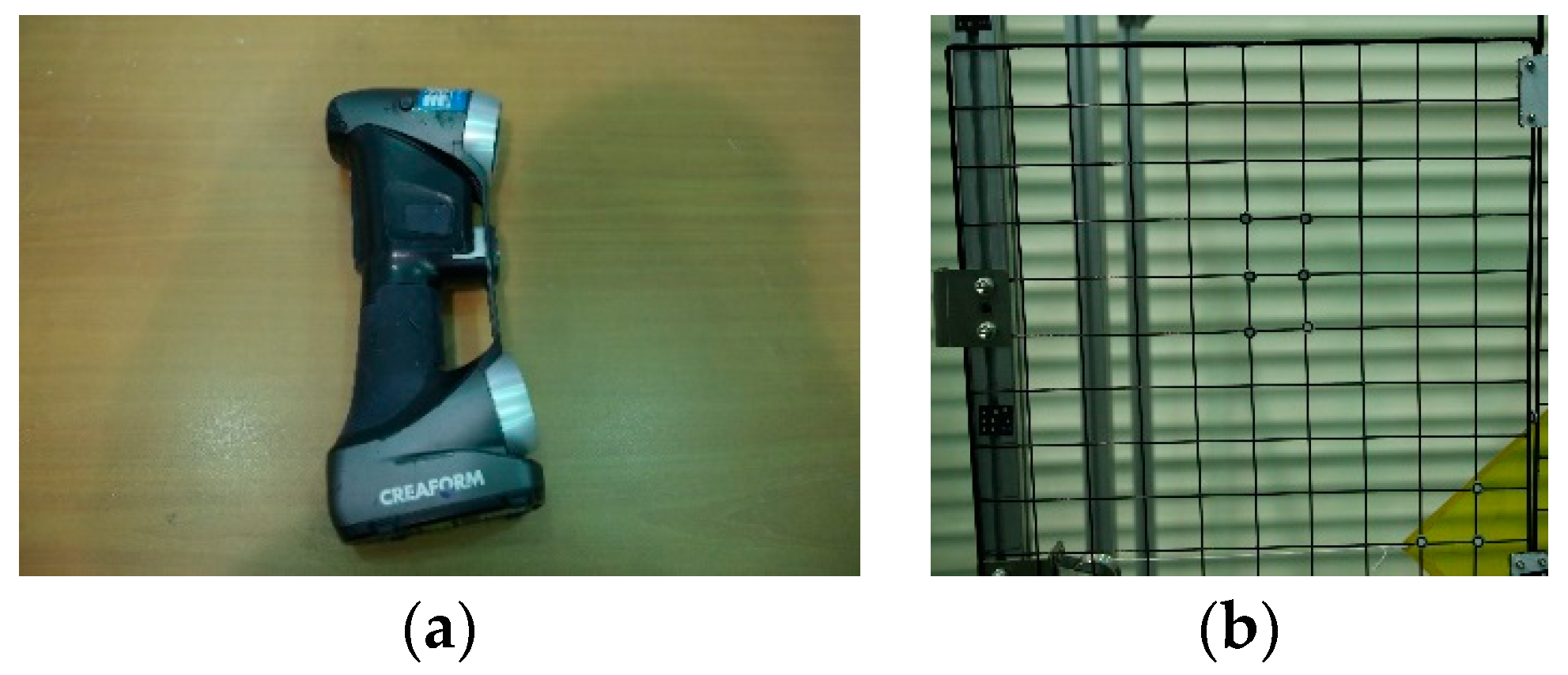
The photogrammetry system is a single-camera photogrammetry system. Based on digital close-up photogrammetry technology, the system can realize the high-precision measurement of the three-dimensional coordinates of objects pasted with landmarks. The photogrammetric system is mainly composed of a CCD camera, landmarks, a datum orientation ruler, and image processing software, as shown in Figure 10. Its technical index is shown in Table 2.
The laser scanning system is a portable three-dimensional laser scanning system. Combined with the photogrammetry system, the system can realize the high-precision scanning of the measured object under the global control of the global precision control network established by the photogrammetry system. The laser scanning system mainly includes a portable laser scanner, an online cable, a calibration board, measurement accessories, and software, as shown in Figure 11. Its technical index is shown in Table 3. Due to the limit of the measurement rate, this system is only suitable for measuring the static deformation of the structure.
The specific experimental process is as follows:
  • Make a membrane of corresponding size and spray the imaging agent on one side to increase the reflection rate;
  • Install the membrane on the test piece system and adjust the weight or adjust the position of the pulley to make the value and direction of the force meet the requirements of the experimental working conditions;
  • Use the CCD camera to take multiple photos of the experimental piece system from different angles;
  • Import the photos into the image processing software to calibrate the coordinate system of the measurement system;
  • Use the portable laser scanner to scan the membrane to obtain the scanning results;
  • Repeat steps 2 to 5 until the measurements of all working conditions are completed.

4.2. Result and Analysis

The maximum amplitude of a membrane wrinkle is the most intuitive index. Therefore, the correctness of the wrinkling analysis method is verified by comparing the experimental measurement results and simulation analysis results under different working conditions. The error η between the experimental measurement results and the simulation analysis results is expressed by
η = v s v t v t × 100 % ,
where, v s is the maximum amplitude of the wrinkle obtained by the simulation and v t is the maximum amplitude of the wrinkle measured by the experiment.

4.2.1. Square Membrane

Various forms of wrinkles under different diagonal forces were measured. The longitudinal diagonal force is F 1 , and the transverse diagonal force is F 2 , as shown in Figure 12.
We kept F 1 unchanged and gradually increased the value of F 2 . The wrinkling shape measured by the experimental system is shown in Figure 13. It can be seen from the results that the transverse wrinkles became increasingly obvious until they ran through the whole membrane, and the wrinkling amplitude grew.
The variation of the maximum amplitude of the wrinkle is shown in Figure 14. When F 2 = 5   N , the maximum amplitude is 4.73 mm and the error is 7.4%, compared to 5.08 mm in the simulation analysis results. When F 2 = 10   N , the maximum amplitude is 7.61 mm, and the error is 51% compared to 11.5 mm in the simulation analysis results.
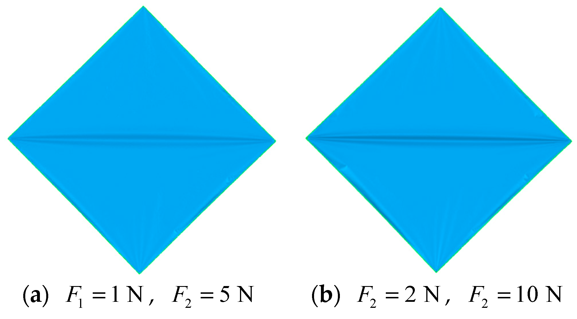
We kept F 2 / F 1 unchanged and increased the value of F 1 and F 2 . The wrinkling shape measured by the experimental system is shown in Figure 15. It can be seen from the results that the wrinkling shape is basically the same under the same condition, but with the increase in force, the wrinkling amplitude increased significantly. When F 1 = 1   N and F 2 = 5   N , the maximum amplitude of the wrinkle is 4.73 mm, and the error is 7.4% compared to 5.08 mm in the simulation analysis results. When F 2 = 2   N and F 2 = 10   N , the maximum amplitude of the wrinkle is 6.64 mm, and the error is 65% compared to 10.96 mm in the simulation analysis results.
In comparing the simulation analysis results with the experimental results, it can be found that when the force is small, the error between the simulation analysis results and the experimental results is small, but when the force becomes great enough, the error is relatively large. There are two reasons. On the one hand, in the simulation analysis, when the force is large, such as 10 N, it can be clearly seen that the calculation result is difficult to converge, and the obvious buckling phenomenon also occurs in the four sides of the membrane. Therefore, the nonlinearity of the whole calculation is greatly enhanced, and the calculation accuracy of the result is thus significantly affected. On the other hand, the square membrane test piece is cut by hand, which has certain defects, and thus it is not completely symmetrical. When the force becomes great, the defects of the membrane are amplified, resulting in the increase in the error of the measurement results.

4.2.2. Trapezoidal Membrane

The effects of the different forces on the wrinkle were measured. The values of the forces were F 1 and F 2 respectively, and the directions were α 1 and α 2 respectively, as shown in Figure 16.
We kept α 1 = α 2 = 30 unchanged and increased the value of F 1 and F 2 . The wrinkling shape measured by the experiment system is shown in Figure 17. It can be seen from the results that when the force direction is unchanged, by increasing F 1 and F 2 , the membrane will gradually wrinkle. When the force is small, the membrane is not fully stretched, and the external environment is easy to affect the membrane during the measurement process. Therefore, the measurement results are not referential. When the tension is 5 N, the maximum amplitude of the wrinkle is 0.87 mm, and the error is 3.4% compared to 0.90 mm in the simulation analysis results. When the force is 10 N, the maximum amplitude of the wrinkle is 0.99 mm, and the error is 26.3% compared to 1.25 mm in the simulation analysis results.
We kept F 1 = F 2 = 10   N unchanged and changed α 1 and α 2 . The wrinkling shape measured by the experiment system is shown in Figure 18. It can be seen from the results that the amplitude and shape of the wrinkle change with the direction of the force.
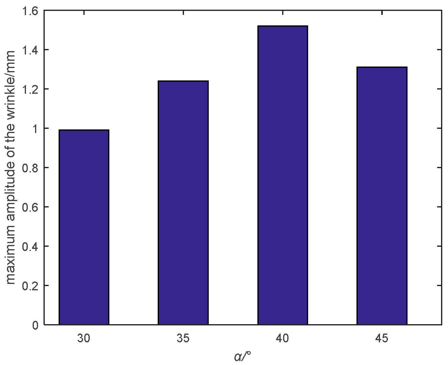
The variation of the maximum amplitude of the wrinkle with the direction of the force is shown in Figure 19. When α 1 = α 2 = 35 , the maximum amplitude of the wrinkle is 1.24 mm, and the error is 40% compared to 1.74 mm in the simulation analysis results. With the increase in α ,the force direction gradually approaches the edge of the membrane, and so the membrane is more prone to buckling and forming wrinkles, resulting in the increase in amplitude. However, since the edge hemming of the membrane adopts a manual viscose, when α 1 = α 2 = 45 , the force direction is too close to the edge and the wrinkle is affected by the edge hemming, and so the wrinkling amplitude does not continue to increase, but decreases instead.
In comparing the simulation analysis results with the experimental results, it can be found that when the force direction is unchanged and force is relatively small, the error between the simulation calculation results and the experimental results is very small, but when the force is relatively large, the error will be large, which is caused by the error in the manufacturing process of the trapezoidal membrane test piece. The error includes the incomplete symmetry of the structure. When the force is relatively large, the asymmetry of the structure is amplified, resulting in large errors in the experimental results. On the other hand, when the force is constant and force direction deviates farther from the angle bisector, it also leads to an increase in the error between the simulation calculation results and the experimental results, which is also caused by the error in the manufacturing process of the trapezoidal film test piece. The error includes the incomplete symmetry of the structure, the membrane irregularity, and the local stress caused by the error of manual hemming. When the force direction is gradually closer to the edge, the asymmetry of the structure is amplified, and the uneven membrane surface and local stress of the edging will also affect the measurement results, resulting in errors in the experimental results.

5. Conclusions

In order to verify the correctness of the wrinkling analysis method, this paper designs and develops a wrinkling measurement system and carries out wrinkling measurement experiments on square and trapezoidal solar sails. In the square membrane test, when F 1 = 1   N and F 2 = 5   N , the error between the simulation analysis results and the experimental results is only 7.4%, and in the trapezoidal film test, when α 1 = α 2 = 30 , and the force is 5 N, the error between the simulation analysis results and the test measurement results is only 3.4%, which verifies the correctness of the wrinkling analysis method and the simulation results. For other test conditions, the error between the simulation analysis results and the experimental results is relatively large. The main reason is that there are many errors in the manufacturing process of the solar sail membrane test piece, including the incomplete symmetry of the structure, the local stress, and the uneven membrane surface of the manual cutting and hemming, as well as the defects of the test piece itself. When the force is large, these errors are amplified, resulting in large errors in the experimental results.

Author Contributions

Conceptualization, J.Z. and D.L.; methodology, J.Z. and J.W.; software, J.Z. and Y.Y.; validation, J.Z. and Y.Y.; formal analysis, J.Z.; investigation, J.Z.; resources, J.Z. and Y.Y.; data curation, J.Z. and Y.Y.; writing—original draft preparation, J.Z.; writing—review and editing, J.Z.; visualization, J.Z.; supervision, D.L. and J.W.; project administration, D.L.; funding acquisition, J.W. All authors have read and agreed to the published version of the manuscript.

Funding

This work is supported by the National Natural Science Foundation of China (No. 11802335) and the National Natural Science Foundation of China (No. 11702321).

Conflicts of Interest

The authors declare no conflict of interest.

References

  1. Spencer, D.A.; Johnson, L.; Long, A.C. Solar sailing technology challenges. Aerosp. Sci. Technol. 2019, 93, 105276. [Google Scholar] [CrossRef]
  2. Tsuda, Y.; Mori, O.; Funase, R.; Sawada, H.; Yamamoto, T.; Saiki, T.; Endo, T.; Kawaguchi, J. Flight status of IKAROS deep space solar sail demonstrator. Acta Astronaut. 2011, 69, 833–840. [Google Scholar] [CrossRef]
  3. Johnson, L.; Whorton, M.; Heaton, A.; Pinson, R.; Laue, G.; Adams, C. NanoSail-D: A solar sail demonstration mission. Acta Astronaut. 2011, 68, 571–575. [Google Scholar] [CrossRef] [Green Version]
  4. Johnson, L.; Young, R.; Montgomery, E.; Alhorn, D. Status of solar sail technology within NASA. Adv. Space Res. 2011, 48, 1687–1694. [Google Scholar] [CrossRef] [Green Version]
  5. Spencer, D.A.; Betts, B.; Bellardo, J.M.; Diaz, A.; Plante, B.; Mansell, J.R. The LightSail 2 solar sailing technology demonstration. Adv. Space Res. 2021, 67, 2878–2889. [Google Scholar] [CrossRef]
  6. Underwood, A.V.C.; Schenk, M.; Fellowes, S.; Taylor, B.; Massimiani, C.; Duke, R.; Stewart, B.; Bridges, C.; Masutti, D.; Denis, A. The InflateSail CubeSat mission: The first European demonstration of drag-sail de-orbiting. In Proceedings of the 4th AIAA Conference on University Satellite Missions and CubeSat Workshop 2017, Rome, Italy, 4–7 December 2017. [Google Scholar]
  7. Viquerat, A.; Schenk, M.; Lappas, V.; Sanders, B. Functional and Qualification Testing of the InflateSail Technology Demonstrator. In Proceedings of the 2nd AIAA Spacecraft Structures Conference, American Institute of Aeronautics and Astronautics 2015, Kissimmee, FL, USA, 5–9 January 2015. [Google Scholar]
  8. Seefeldt, P. A stowing and deployment strategy for large membrane space systems on the example of Gossamer-1. Adv. Space Res. 2017, 60, 1345–1362. [Google Scholar] [CrossRef]
  9. Seefeldt, P.; Spietz, P.; Sproewitz, T.; Grundmann, J.T.; Hillebrandt, M.; Hobbie, C.; Ruffer, M.; Straubel, M.; Tóth, N.; Zander, M. Gossamer-1: Mission concept and technology for a controlled deployment of gossamer spacecraft. Adv. Space Res. 2017, 59, 434–456. [Google Scholar] [CrossRef] [Green Version]
  10. McNutt, L.; Johnson, L.; Kahn, P.; Castillo-Rogez, J.; Frick, A. Near-Earth Asteroid (NEA) Scout. In Proceedings of the AIAA SPACE 2014 Conference and Exposition, American Institute of Aeronautics and Astronautics 2014, San Diego, CA, USA, 4–7 August 2014. [Google Scholar]
  11. Matsushita, M.; Chujo, T.; Matsumoto, J.; Mori, O.; Yokota, R.; Toyota, H.; Satou, Y.; Okuizumi, N.; Kato, H.; Nakamura, T.; et al. Solar power sail membrane prototype for OKEANOS mission. Adv. Space Res. 2021, 67, 2899–2911. [Google Scholar] [CrossRef]
  12. Mengali, G.; Quarta, A.A. Rapid Solar Sail Rendezvous Missions to Asteroid 99942 Apophis. J. Spacecr. Rocket. 2009, 46, 134–140. [Google Scholar] [CrossRef]
  13. Bianchi, C.; Niccolai, L.; Mengali, G.; Quarta, A.A. Collinear artificial equilibrium point maintenance with a wrinkled solar sail. Aerosp. Sci. Technol. 2021, 119, 107150. [Google Scholar] [CrossRef]
  14. Wagner, H. Flat Sheet Metal Girders with Very Thin Metal Webs. Part I II III NACA Tech Memo. 1929, 20, 200–314. [Google Scholar]
  15. Friswell, M.I.; Garvey, S.D.; Penny, J.E.T. Model reduction using dynamic and iterated IRS techniques. J. Sound Vib. 1995, 186, 311–323. [Google Scholar] [CrossRef]
  16. Dyka, C.T.; Ingel, R.P.; Flippen, L.D. A new approach to dynamic condensation for FEM. Comput. Struct. 1996, 61, 763–773. [Google Scholar] [CrossRef]
  17. Wu, C.-H. Nonlinear Wrinkling of Nonlinear Membranes of Revolution. J. Appl. Mech. 1978, 45, 533–538. [Google Scholar] [CrossRef]
  18. Martins, A.D.; Silvestre, N.; Bebiano, R. A new modal theory for wrinkling analysis of stretched membranes. Int. J. Mech. Sci. 2020, 175, 105519. [Google Scholar] [CrossRef]
  19. Lecieux, Y.; Bouzidi, R. Experimental analysis on membrane wrinkling under biaxial load—Comparison with bifurcation analysis. Int. J. Solids Struct. 2010, 47, 2459–2475. [Google Scholar] [CrossRef] [Green Version]
  20. Vulpetti, G.; Apponi, D.; Zeng, X.; Circi, C. Wrinkling analysis of solar-photon sails. Adv. Space Res. 2021, 67, 2669–2687. [Google Scholar] [CrossRef]
  21. Wong, Y.W.; Pellegrino, S. Wrinkled membranes part I: Experiments. J. Mech. Mater. Struct. 2006, 1, 15–23. [Google Scholar] [CrossRef] [Green Version]
  22. Bernal, R.; Tassius, C.; Melo, F. Elastic response and wrinkling onset of curved elastic membranes subjected to indentation test. Eur. Phys. J. E 2011, 34, 13. [Google Scholar] [CrossRef] [Green Version]
  23. Murphy, D.M.; Macy, B.D. Demonstration of a 10-m Solar Sail System. In Proceedings of the 45th AIAA/ASME/ASCE/AHS/ASC Structures, Structural Dynamics & Materials Conference, Palm Springs, CA, USA, 19–22 April 2004. [Google Scholar]
  24. Deng, X.; Xu, Y.; Clarke, C. Wrinkling modelling of space membranes subject to solar radiation pressure. Compos. Part B Eng. 2019, 157, 266–275. [Google Scholar] [CrossRef]
  25. Pino, T.; Circi, C.; Vulpetti, G. Wrinkling analysis for small solar-photon sails: An experimental and analytic approach for trajectory design. Adv. Space Res. 2019, 63, 3675–3690. [Google Scholar] [CrossRef]
  26. Contri, B.A.S.P. A Geometrically Nonlinear Finite Element Analysis of Wrinkled Membrane Surfaces by a No-compression MaterialL Model. Commun. Appl. Numer. Methods 1988, 4, 5–15. [Google Scholar] [CrossRef]
Figure 1. Solar sail model: (a) quadrilateral solar sail; (b) hexagonal solar sail; (c) 1/6 hexagonal solar sail; and (d) hemming and metal ring structure.
Aerospace 09 00289 g001
Figure 2. Loading diagram and finite element model of a square membrane’s wrinkling analysis: (a) loading diagram; and (b) finite element model.
Aerospace 09 00289 g002
Figure 3. Simulation analysis results of the wrinkling shape ( F 1 unchanged): (a) F 1 = 1   N and F 2 = 5   N ; and (b) F 1 = 1   N and F 2 = 10   N .
Aerospace 09 00289 g003
Figure 4. Simulation analysis results of the wrinkling shape ( F 2 / F 1 unchanged): (a) F 1 = 1   N and F 2 = 5   N ; and (b) F 2 = 2   N and F 2 = 10   N .
Aerospace 09 00289 g004
Figure 5. Loading diagram and finite element model of a trapezoidal membrane’s wrinkling analysis: (a) loading diagram; and (b) finite element model.
Aerospace 09 00289 g005
Figure 6. Simulation analysis results of the wrinkling shape when increasing the force ( α 1 = α 2 = 30 ): (a) F 1 = F 2 = 5   N ; and (b) F 1 = F 2 = 10   N .
Aerospace 09 00289 g006
Figure 7. Simulation analysis results of the wrinkling shape when changing the force direction. (a) α 1 = α 2 = 30 . (b) α 1 = α 2 = 35 .
Aerospace 09 00289 g007
Figure 8. Schematic diagram of the wrinkling measurement system: (a) square membrane; and (b) trapezoidal membrane.
Aerospace 09 00289 g008
Figure 9. Test piece system: (a) square membrane; and (b) trapezoidal membrane.
Aerospace 09 00289 g009
Figure 10. Composition of the photogrammetry system: (a) CCD camera; (b) datum orientation ruler; and (c) landmark.
Aerospace 09 00289 g010
Figure 11. Composition of the laser scanning system: (a) portable laser scanner; and (b) measurement accessories.
Aerospace 09 00289 g011
Figure 12. Schematic diagram of the diagonal force in the square membrane experiment.
Aerospace 09 00289 g012
Figure 13. Experimental results of the wrinkling shape for the square membrane ( F 1 unchanged): (a) F 1 = 1   N and F 2 = 1   N ; (b) F 1 = 1   N and F 2 = 2   N ; (c) F 1 = 1   N and F 2 = 5   N ; and (d) F 1 = 1   N and F 2 = 10   N .
Aerospace 09 00289 g013
Figure 14. Experimental results of the maximum amplitude of the wrinkle for the square membrane ( F 1 unchanged).
Aerospace 09 00289 g014
Figure 15. Experimental results of the wrinkling shape for the square membrane( F 2 / F 1 unchanged): (a) F 1 = 1   N and F 2 = 5   N ; and (b) F 1 = 2   N and F 2 = 10   N .
Aerospace 09 00289 g015
Figure 16. Schematic diagram of the forces in the trapezoidal membrane experiment.
Aerospace 09 00289 g016
Figure 17. Experimental results of the wrinkling shape for the trapezoidal membrane ( α 1 = α 2 = 30 unchanged): (a) F 1 = F 2 = 1   N ; (b) F 1 = F 2 = 2   N ; (c) F 1 = F 2 = 5   N ; and (d) F 1 = F 2 = 10   N .
Aerospace 09 00289 g017
Figure 18. Experimental results of the wrinkling shape for the trapezoidal membrane ( F 1 = F 2 = 10   N unchanged): (a) α 1 = α 2 = 30 ; (b) α 1 = α 2 = 35 ; (c) α 1 = α 2 = 40 ; and (d) α 1 = α 2 = 45 .
Aerospace 09 00289 g018
Figure 19. Experimental results of the maximum amplitude of the wrinkle for the trapezoidal membrane ( F 1 = F 2 = 10   N unchanged).
Aerospace 09 00289 g019
Table 1. Material parameters of membrane.
MaterialElastic ModulusPoisson’s RatioDensity
polyimide5 Gpa0.371330 kg/m3
Table 2. Technical index of the photogrammetry system.
ResolutionSpatial Measurement AccuracyDeformation Measurement AccuracyField Angle
16 m0.020 mm (≤4 m)0.01 mm84°
Table 3. Technical index of the laser scanning system.
Measurement RateSingle Scanning AreaMinimum Interval between PointsAccuracy
480,000 points/s275 × 250 mm0.03 mm0.02 mm
Publisher’s Note: MDPI stays neutral with regard to jurisdictional claims in published maps and institutional affiliations.