Article

Low-Cost Satellite Launch System—Aerodynamic Feasibility Study

by
Aleksander Olejnik
1,
Łukasz Kiszkowiak
1,*,
Piotr Zalewski
1 and
Adam Dziubiński
2
1
Faculty of Mechatronics, Armament and Aerospace, Military University of Technology, 00-908 Warsaw, Poland
2
Aerodynamics Department, Łukasiewicz Research Network—Institute of Aviation, 02-256 Warsaw, Poland
*
Author to whom correspondence should be addressed.
Aerospace 2022, 9(6), 284; https://doi.org/10.3390/aerospace9060284
Submission received: 29 March 2022 / Revised: 16 May 2022 / Accepted: 19 May 2022 / Published: 24 May 2022
(This article belongs to the Section Astronautics & Space Science)

Abstract

:
In recent decades, the rapid development of alternative methods for launching satellites into space has been observed. The main purpose of this work is to obtain reliable information about aerodynamic properties, which will be useful in the preliminary design of a low-cost satellite launch system based on a system consisting of a carrier aircraft and a space rocket orbiter. The numerical geometry of the aircraft carrier was developed as a result of the digitization process of the external surface of a real aircraft. Aerodynamic analysis was performed using specialized software based on solving partial differential equations using the finite volumes method. The results of the aerodynamic analysis were presented in a quantitative and qualitative manner. Furthermore, in order to confirm the correctness of the chosen method, the obtained results were compared with the results of experimental tests carried out in a wind tunnel. This will also prove that the adopted method is sufficient for solving this type of problem. The main advantage of the presented method is obtainment of reliable results in a relatively short time, which is extremely important during the preliminary design stage. The results presented in this paper will certainly be helpful for all researchers involved in the development of new and low-cost methods for launching small satellites into LEO.

1. Introduction

One of the most important factors that determines the possibility of launching satellites into space is the total cost of this process. Therefore, the high cost of a launch is the main limiting factor to commercial exploration of near-Earth space. One way to significantly reduce this cost is to launch a space rocket from an aerial platform, e.g., decommissioned combat aircraft that have the performance necessary to fulfill this task. For various countries, this can be the only way to achieve the capabilities to take science or communication microsatellites into low Earth orbit (LEO). In addition, reducing the cost of launching objects into space may increase the number of very small, highly specialized satellites that are being developed at many universities [1,2].
Air launch to orbit is the method of launching carrier rocket vehicles at the maximum achievable altitude from a conventional horizontal-takeoff aircraft in order to insert small satellites into low Earth orbit (LEO). This is a follow-up development on the air launches of experimental aircraft that began in the late 1940s. The Stargazer–Pegasus from Orbital ATK, developed in the 1990s (Northrop Grumman Corporation, 2020), is currently the oldest operating system. Use of such a system consists of a modified Lockheed Tri Star passenger aircraft and a Pegasus XL three-stage space missile carried under its fuselage; space payloads with a total mass of up to 443 kg are launched [3]. In 2006, Boeing presented [4] the concept of launching a space rocket on the back of a Boeing F-15 supersonic combat aircraft as an alternative responsive air launch system to the “classic” rocket launching from Earth. Similar systems were analyzed and discussed in later works [5,6,7,8,9,10,11], where supersonic airplanes were proposed as carriers for and launch platforms of space rockets, e.g., F-16 [7] or MiG-31 [11]. Currently, the aviation of the Polish Armed Forces is withdrawing from use of MiG-29 and Su-22 planes, which can be used as responsive space assets.
At present, Poland does not have any system for launching satellites into Earth’s orbit. The ability to take microsatellites or nanosatellites into LEO is the main reason why Poland has neither civil nor military communication or reconnaissance satellites. In this context, it is reasonable to develop in Poland their own independent load-lifting system that will become a factor of progress in the development of the national space technology. As a result, Poland would achieve completely new capabilities in space technology, which until now have been reserved for countries possessing and developing space technologies. The development and analysis of the possibilities of such a system would be a great opportunity for Polish technical universities as well as legal entities and companies that would like to invest their resources in the broadly understood space segment.
A preliminary analysis showed that a modernized MiG-29 aircraft (operated by the Polish Armed Forces) could be used as an aviation platform capable of carrying a space rocket weighing up to 4000 kg, which would allow micro- and nanosatellites to be transported into orbit. Furthermore, the second stage of the rocket W-755 from the S-75M anti-aircraft system “Volkhov”, known in the West as SA-2C “Guideline”, was selected as a space rocket orbiter [12].
The main purpose of this work is to obtain, using CFD methods, reliable information on the aerodynamic properties of carrier aircraft and a space rocket orbiter’s assembly. The aerodynamic properties of the launch vehicles also affect a vehicle’s trajectory. Therefore, it is extremely important to know the reliable aerodynamic characteristics of the airplane–rocket assembly. Moreover, the applied method allows for analysis of the influence of individual elements of the assembly on aircraft aerodynamic properties. In order to acquire this information, the authors decided to use an ANSYS Fluent v.15 software (ANSYS Fluent v.15, Canonsburg, PA, USA) [13] based on solving partial differential equations using the finite volumes method. Various science papers [14,15,16,17,18] show the possibilities for using numerical methods to possess overall information regarding the aerodynamic characteristics of aircraft or their parts. Bearing this fact in mind, this article’s novelty is based mainly on the use of CFD methods to analyze the aerodynamic properties of a complex geometry airplane carrier with a space rocket orbiter. Furthermore, in order to confirm the correctness of the chosen method, the obtained results are compared with the results of experimental tests carried out in a wind tunnel. The article also proves that the adopted method is sufficient for solving this type of problem.
The following sections of this paper describe both the stages and process for preparing the necessary computational model during the phase of numerical aerodynamic analysis. Section 3 shows the quantitative and qualitative results of the performed analysis, and the last section concludes the paper with final remarks.

2. Materials and Methods

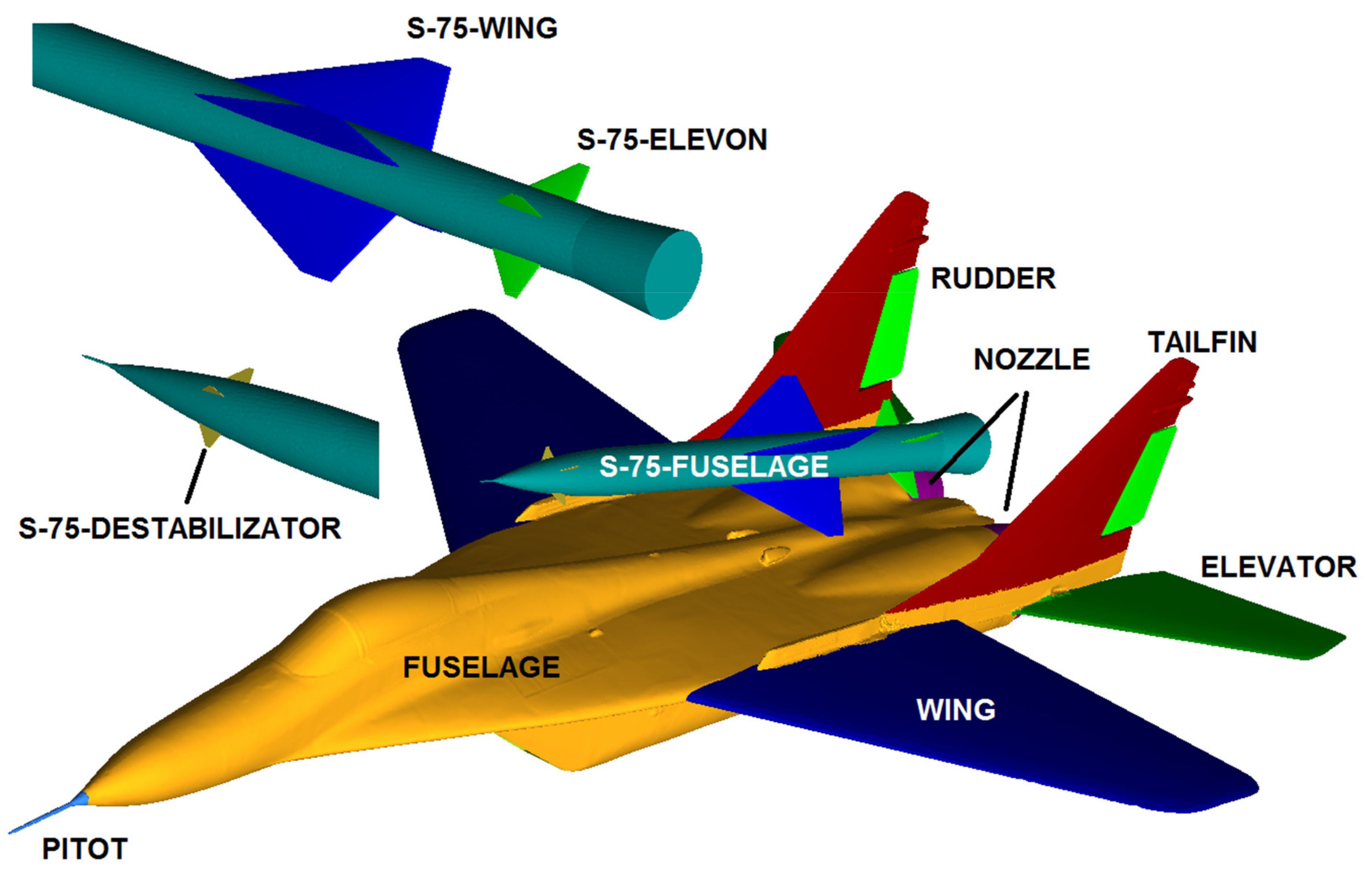
2.1. Development of Aircraft CAD Model Using Reverse Engineering Methods

To analyze the forces acting on an airplane during flight, there is a need to develop an external geometry model. The geometric model is a starting point for developing a series of models for numerical and experimental analysis of various phenomena. During the digitization process of an aircraft’s outer surface, the optical scanning system ATOS II Triple Scan was used. This system is based on the optical triangulation method. Precise fringe patterns are projected onto the surface of the object and are captured by two cameras based on the stereo camera principle. As the beam paths of both cameras and the projector are known in advance due to calibration, the 3D coordinate points from three different ray intersections can be calculated. This triple scan principle offers advantages for measuring reflective surfaces and objects with indentations. The result is complete measuring data without holes or erratic points. The accuracy of the optical measuring systems is based on state-of-the-art optoelectronics, precise image processing and mathematic algorithms, ensured by stable precision standards and an automated calibration procedure [19,20].
In the next phase of the digitization process, a point cloud was polygonized into a grid of triangles. In this complex process, the scanned surface patches were additionally matched to the rest using the least squares method. The result of this process is an external geometry surface model in triangle grid form. The accuracy of the developed model may be checked using aircraft maintenance documentation, for example. The validation of the model was made at the end of the polygonization process. The characteristic dimensions of the aircraft surface model were determined and compared with data from the documentation. Figure 1 shows partial measurement results regarding the wing, fuselage and tail sections.

2.2. Basic Information on the Applied Method for Determining the Aerodynamic Loads

The dynamic development of microprocessor technology and methods of computational fluid dynamics have enabled the simulation of many phenomena that occur during the flow of fluids around solid bodies. CFD is a branch of fluid mechanics that focuses on the detailed analysis and modeling of flows using numerical methods. In the theory of fluid mechanics, the movement of liquids and gases is described by a system of differential equations [21]:
  • A Navier–Stokes equation (equation of momentum conservation) in the following form:
t ρ v + · ρ v v = p + ( τ ̿ ) + ρ g + F
where:
  • p—static pressure;
  • ρ g and F are, respectively, gravitational forces and external forces, e.g., increasing as a result of flow through a dispersed phase;
  • τ ̿ —stress tensor.
τ ̿ = μ v + v T 2 3 · v I  
where:
  • μ —kinematic viscosity;
  • I—unit matrix.
  • The equation of flow continuity (mass conservation equation in relation to fluid treated as a continuous medium) in the form:
ρ t + · ρ v = S m
where:
  • Sm—mass source (e.g., as a result of evaporation of the dispersed phase).
  • The energy conservation equation in the form:
t ρ E + x i u i ρ E + p = x j k + c p μ t P r t T x j + u i τ i j e f f + S h
where:
  • k—thermal conductivity;
  • E—total energy;
  • τ i j e f f —shear stress tensor.
τ i j e f f = μ e f f u j x i + u i x j 2 3 μ e f f u k x k δ i j
Solving these, in general, is possible only by using numerical methods, e.g., finite volume methods. The above equations are transformed into an integral form:
t Q d V + F d A = 0
in which Q is used to denote the values subject to laws of conservation (of mass, momentum and energy) inside a cell; F is a vector of quantities characterizing the stream exchanged with the cell environment; V is the volume of a single control cell; and A is its external surface. Equations written in this way are solved using an iterative method (successive approximations). The size of the cells in the domain reproducing the air area around the studied geometry is selected to accurately reflect the unevenness of the flow field. Unfortunately, this is a very demanding method when it comes to computing resources, both in terms of used memory and computing performance. In the case of the geometry of an entire aircraft, calculations are most often made on a computer consisting of several to several dozen parallel working units (nodes), in which each analyzes a separate fragment of the computational mesh.
One of the most commonly used packages for solving engineering problems in the field of fluid mechanics and aerodynamics is the ANSYS Fluent software [13], based on solving partial differential equations using the finite volumes method. It enables analysis of incompressible and compressible flows, with optional consideration of flow viscosity. Many turbulence models have been implemented in the program. Motion equations are solved on non-structural (tetrahedral), structural and hybrid meshes.
The ICEM CFD v.15 software (ANSYS ICEM CFD v.15, Canonsburg, PA, USA) [22], which is part of the ANSYS package, was used to generate the computational meshes. The ICEM CFD software is an advanced preprocessing tool that allows one to fully prepare a geometric model, i.e., to build or import geometry from a CAD software, as well as to repair and simplify such geometry. The ICEM CFD software enables the creation of structural and non-structural meshes with tetrahedral, prismatic, hexagonal, pyramidal as well as hybrid meshes consisting of many types of elements. It also offers numerous tools for checking and improving the quality of a mesh. Automatic and manual tools are used to improve the quality of mesh elements by, for example, smoothing, refinement and derefinement of the mesh, as well as, if necessary, relocation of individual nodes inside the domain.

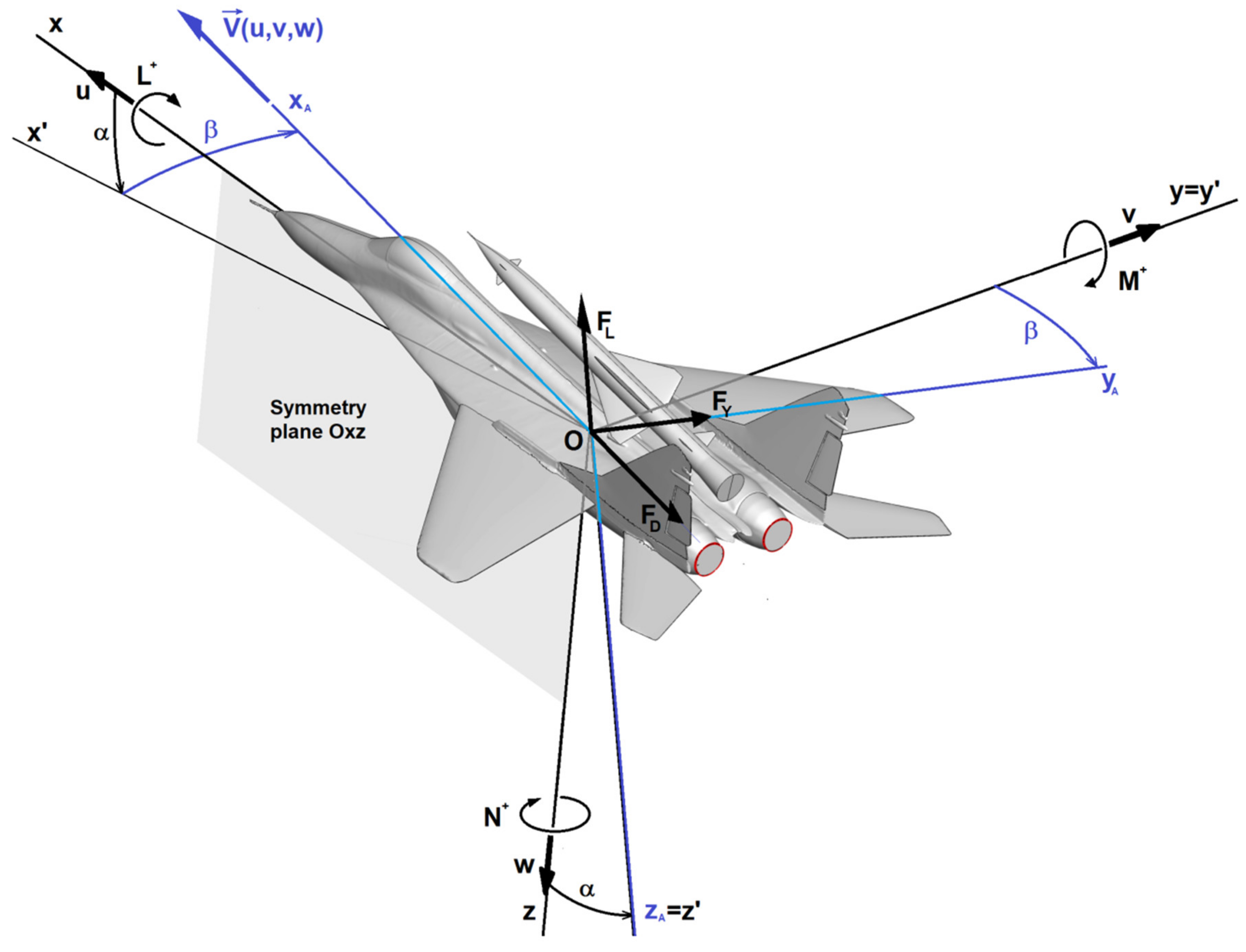
2.3. Coordinate Systems and Determination of Force and Aerodynamic Moment Components

In the course of the aerodynamic tests, rectangular, right-handed coordinate systems in accordance with the appropriate regulations [23] were used, as shown in Figure 2.
The system associated with the aircraft is defined as follows:
the origin of the system lies in the center of mass of the aircraft—point O;
the Oxz plane is the plane of geometrical, mass and aerodynamic symmetry of the aircraft;
the longitudinal axis Ox lies in the plane of symmetry of the aircraft and constitutes the main axis of inertia of the aircraft and is directed towards its nose;
the lateral axis Oy is perpendicular to the plane of symmetry and is directed towards the right wing;
the Oz axis lies in the plane of symmetry of the aircraft and is directed towards the bottom surface of the fuselage.
The flow-related system is determined as follows:
the origin of the system lies in the center of mass of the aircraft—point O;
the longitudinal axis OxA is directed along the vector V of the airplane velocity relative to the air;
the OzA axis lies in the plane of symmetry of the aircraft and is directed towards the bottom surface of the fuselage;
the OyA axis is directed towards the right wing so that the system is right-handed.
The transition angles between the Oxyz and OxAyAzA systems:
the angle of attack α is the angle between the projection of the velocity vector V on the aircraft plane of symmetry Oxz and the aircraft longitudinal axis Ox;
the angle of bank β is the angle between the velocity vector V and the aircraft plane of symmetry Oxz.
In the course of the performed research, values of the coefficients of force and aerodynamic moment components were determined from the following relationships [21,24]:
drag force coefficient
C D = 2 · F D ρ · v 2 · S
side force coefficient
C Y = 2 · F Y ρ · v 2 · S
lift force coefficient
C L = 2 · F L ρ · v 2 · S
rolling moment coefficient
C l = 2 · L ρ · v 2 · S · b
pitching moment coefficient
C m = 2 · M ρ · v 2 · S · M A C
yawing moment coefficient
C n = 2 · N ρ · v 2 · S · b
where:
  • FD—drag force [N];
  • FY—side force [N];
  • FL—lift force [N];
  • L—rolling moment [Nm];
  • M—pitching moment [Nm];
  • N—yawing moment [Nm];
  • ρ —undisturbed air density [kg/m3];
  • v —undisturbed air flow velocity magnitude [m/s];
    S—wing area [m2];
  • b—wingspan [m];
  • MAC—mean aerodynamic chord [m];

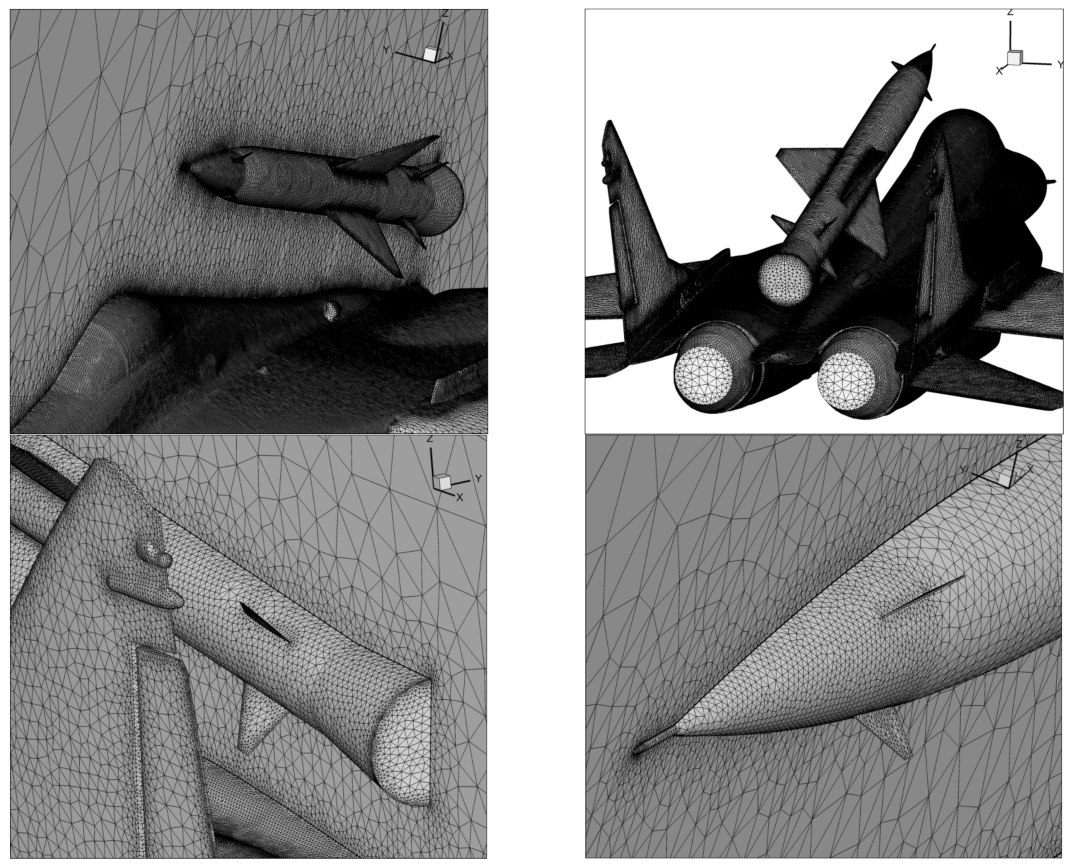
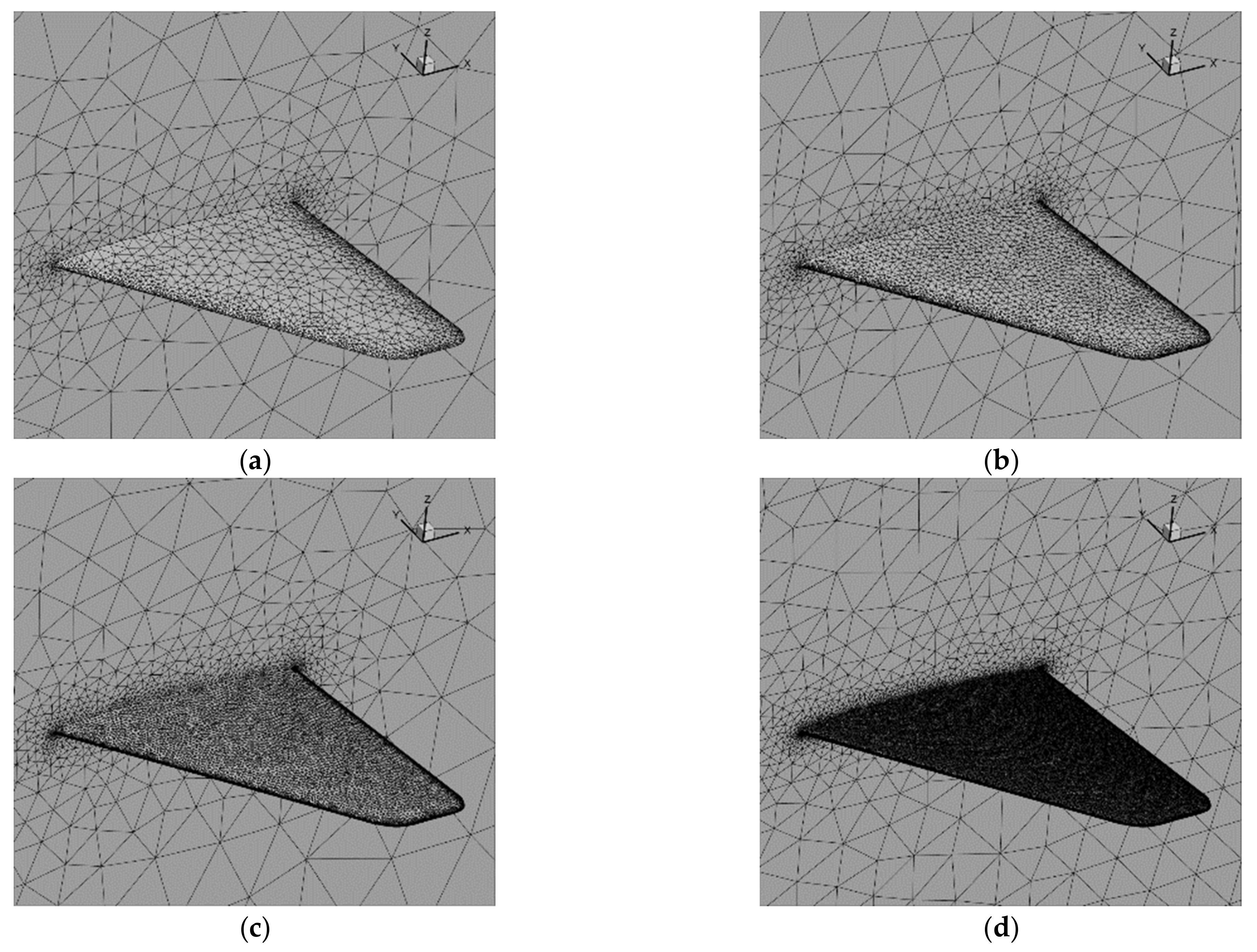
2.4. Development of Aircraft and Rocket Numerical Models for CFD Analysis

The geometry of the aircraft was developed as a result of the digitization of the outer surface of the aircraft. Thanks to the use of specialized research equipment and research staff with extensive experience in this field, a reliable geometric model was obtained, characterized by a very accurate representation of the aircraft’s surfaces. In order to prepare the numerical model of the aircraft for aerodynamic analyses, introduction of the appropriate corrections into the obtained surface geometry were required, enabling generation of the computational mesh. Alternatively, the geometry of the second stage of the W-755 missile was reproduced on the basis of information found in publicly available literature in this field and photographic documentation [12,19,20].
The angle of inclination of the space rocket was set to correspond to the upper surface of the fuselage in order to minimize the drag and allow for safe separation. The space rocket’s center of gravity was set to be near the carrier aircraft’s center of gravity, while, most importantly, allowing for safe ejection from a cockpit.
A non-structural mesh was generated in the area surrounding the aircraft’s airframe and the space rocket. The rectangular domain around the model size of 100 × 45 × 100 representing half of the geometry is presented in Figure 3. The size of the computational mesh was about 5.2 million cells. Five layers of prism cells simulating the boundary layer were generated around the walls of the aircraft and the rocket.
The thickness of the first mesh element (0.6 mm) corresponded to the turbulence parameter y+ in the range <30–200>, which is recommended for the Spalart–Allmaras turbulence model used. This model is adopted as a standard in the analysis of external flows, especially in the range of Reynolds numbers used in aviation [21]. The selected mesh size and turbulence model allowed for the attainment of reliable results with a reasonable calculation time. In this case, the possible increase in the accuracy of the results obtained by the use of more complex turbulence models is relatively small compared to the large increase in the computational cost. Furthermore, the influence of the turbulence model, in terms of the comparison presented in work [25], shows no significant change in the characteristics corresponding to the linear part of the CL.
Figure 4 shows the density of the computational mesh generated on the basis of geometric models of the combat aircraft and the space rocket. Of note is the higher mesh density in the areas of expected high variability of the flow parameters being determined. Such areas include, but are not limited to, leading edges and trailing edges of the wing and control surfaces, areas around engine inlets and outlets, the fuselage nose, the wing–fuselage connection area and areas of significant change in the surface curvature.
A mesh-size grid independence study was done for a model containing only the wing. A remeshing of the full computational model containing the carrier aircraft and space rocket would be very difficult and time-consuming due to the complexity of the geometry. The aircraft computational model is detailed, as it was created as a result of the digitization process of a real aircraft. This allows a more realistic aircraft drag to be considered, including even small details of the real airframe. However, it is problematic for use in the ICEM and requires a lot of manual work to repair the mesh after the boundary layer model has been generated. Subsequently, a set of four test meshes (Figure 5) of different sizes, including only the WING part, was tested, and the results are shown in Figure 6. The analyses were performed for α = 6° and Ma = 0.268.
The error for each mesh size was calculated using following formula:
δ = ((PZAi – PZAfinal)/PZAfinal) × 100%
where:
  • PZA—aerodynamic lift force;
  • i—index number of actual mesh;
  • final—index number of largest mesh.
Since the mesh size of 1,000,000 cells was generating only 0.19% of an approximation error, but its calculation time is four times lower than the largest one, this mesh size was selected for further calculations. The computation time of the full mesh for each angle of attack was about 6 h (10 days per one characteristic vs AoA, in comparison to 40 days for the densest mesh); therefore, even that simplification was a significant factor.
In the developed calculation models, the WALL boundary condition was used on the surface of the airframe and the space rocket, which is a wall with the condition for turbulence development, i.e., a standard wall function. On the back wall of the domain, the condition PRESSURE OUTLET was assumed, while on the front, top, bottom and side walls, the condition of the far flow field (PRESSURE FAR FIELD) was used (Figure 3). The inlet and outlet surfaces of the aircraft engines and the outlet from the space rocket engine were prepared for the purpose of determining the impact of the engine unit on the aerodynamic characteristics of the object. In this particular simulation, the engines were set as “flow through” (set as pressure inlet and outlet without a pressure jump), which corresponds to the opened engine channels in the wind tunnel experiment.
Due to the adopted method for presenting the results of the calculations, the surfaces of the aircraft and the rocket were divided into appropriate zones, which are shown in Figure 7.
For performing numerical aerodynamic analyses in a symmetrical flow around an object, the following assumptions were made:
symmetry of the flow field;
symmetry of geometry;
the flow is stationary and stable, i.e., there is neither a Karman vortex trail behind the airframe, nor any other non-stationary structure in the flow;
the flight conditions correspond to zero altitude (at sea level), according to the reference atmosphere: pressure P = 101,325 Pa, temperature T = 288.15 K and air density ρ = 1.225 kg/m3.
The position of the pole of the aerodynamic moment was on the plane of symmetry of the aircraft at the point corresponding to the projection of the ¼ SCA point on this plane.
Calculations were performed for the velocity corresponding to Ma = 0.268. This corresponds to the Reynolds number Re = 23 × 106 (for MAC = 3.74 m) for aircraft and Re = 48 × 106 for the space rocket length.

3. Results and Discussion

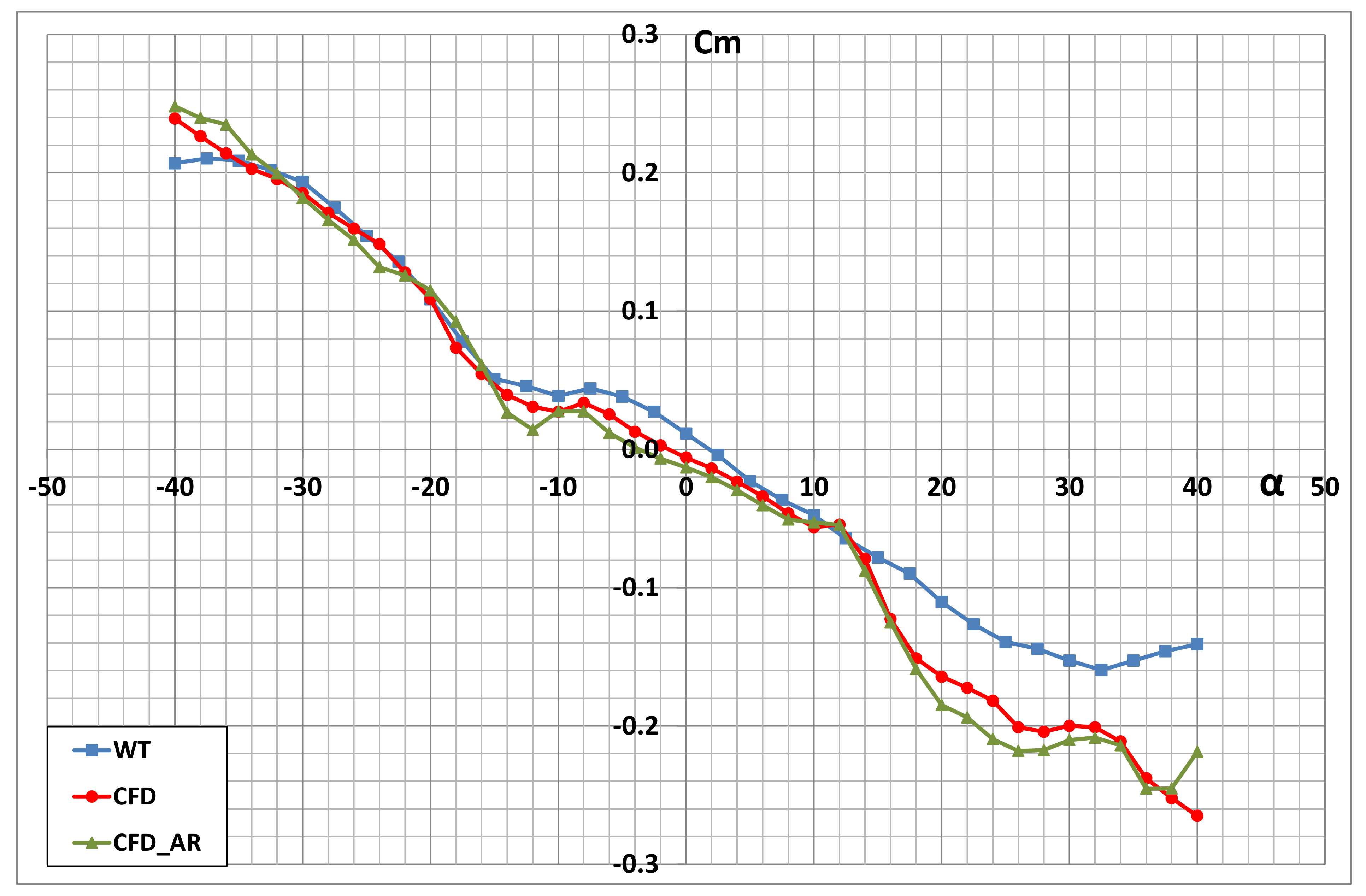
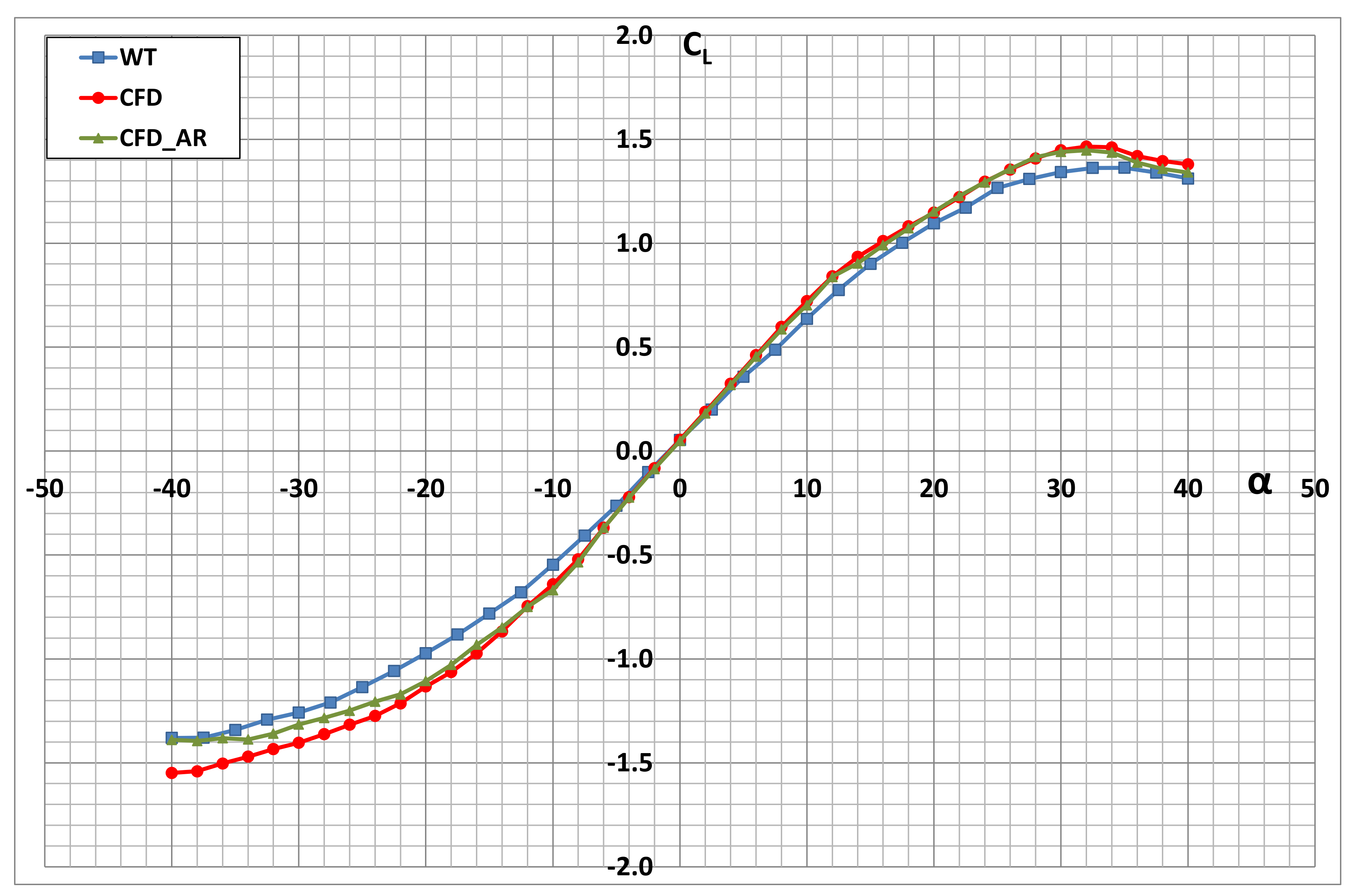
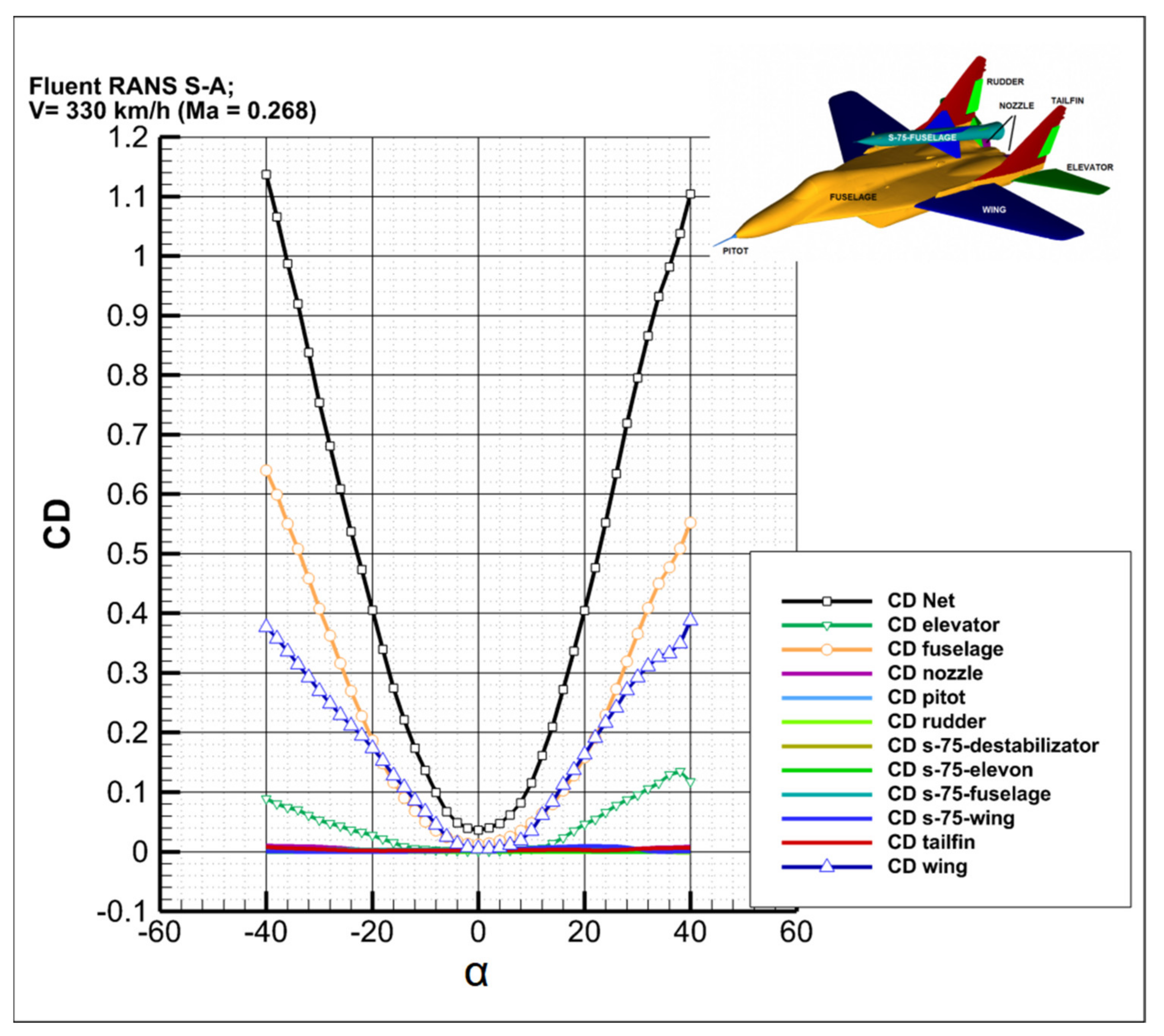
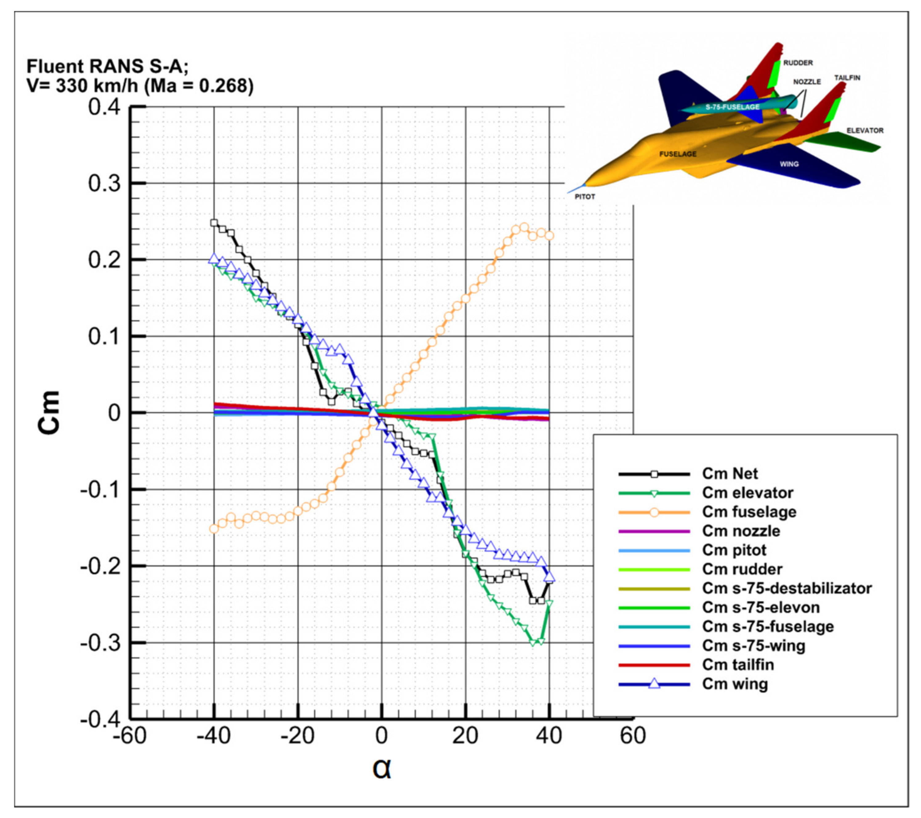
3.1. Quantitative Results

Figure 8, Figure 9, Figure 10 and Figure 11 show a comparison of the results of the numerical analysis in the form of aerodynamic characteristics presented as a function of the angle of attack obtained for the aircraft in the configurations, both without the space rocket (CFD) and with the space rocket (CFD_A+R). The characteristics of the drag coefficient (Figure 8) clearly show that the greatest impact of the space rocket on increasing the value of the drag coefficient can be observed in the range of the angle of attack α = −12°–12°. However, this is a relatively small increase. Furthermore, for angles of attack smaller than α = −28° and larger than α = 38°, the obtained values of the drag coefficient are smaller for the aircraft in the configuration with the space rocket. Nevertheless, on the diagram of the lift coefficient (Figure 9), it can be seen that for angles of attack in the range of α = −20°–32°, the impact of the space rocket on the change in the lift coefficient is negligibly small. A slight decrease in the absolute value of the lift coefficient was obtained for angles of attack smaller than α = −20° and greater than α = 32°.
Regarding the characteristics of the pitching moment coefficient (Figure 10), no significant impact of the space rocket on the change in the aircraft’s stability in the longitudinal channel was observed. The rocket has the strongest impact on the change in the pitching moment coefficient for angles of attack greater than α = 18°. In relation to the adopted pole of the pitching moment, which is in 25% of the SCA, the aircraft in the configurations, both with and without the space rocket, is statically stable in practically the entire range of the analyzed angles of attack.
Conversely, regarding the lift-to-drag ratio characteristics (Figure 11), the greatest impact of the space rocket on the change in the values obtained for individual angles of attack can be observed. The biggest difference was obtained for the maximum lift-to-drag ratio. For the carrier aircraft without the space rocket, it is 9.8, while it is only 7.4 for the aircraft with the rocket. It should be noted that within the range of the analyzed angles of attack, the impact of the space rocket on the change in individual aerodynamic characteristics is small. In addition, the static stability of the aircraft does not change.
Furthermore, the results of the numerical analyses were compared with the results of the experimental tests (WT) carried out in a low-speed wind tunnel of the Institute of Aeronautics of the Faculty of Mechatronics, Armament and Aviation of the Military University of Technology [26]. The tests were carried out for the MiG-29 scale model in the configuration without the space rocket. What draws attention is the large conformance of the results obtained in the numerical analysis with the results of the experimental tests. This indicates the correctness of the developed numerical model of the MiG-29 aircraft for the needs of aerodynamic analysis.
Any possible differences in the values of the individual aerodynamic coefficients result directly from the specifics of the conducted experimental tests, e.g., from different values of the criteria numbers. A 1:20 scale model of the MiG-29 aircraft was used to carry out the tests in the wind tunnel. Therefore, these tests were carried out for Ma = 0.12 and Re = 0.495 × 10⁶. Taking into account that the tail surfaces have very short chords, the greatest impact of the different values of the criteria numbers was observed in the characteristic of pitching moment (Figure 10).

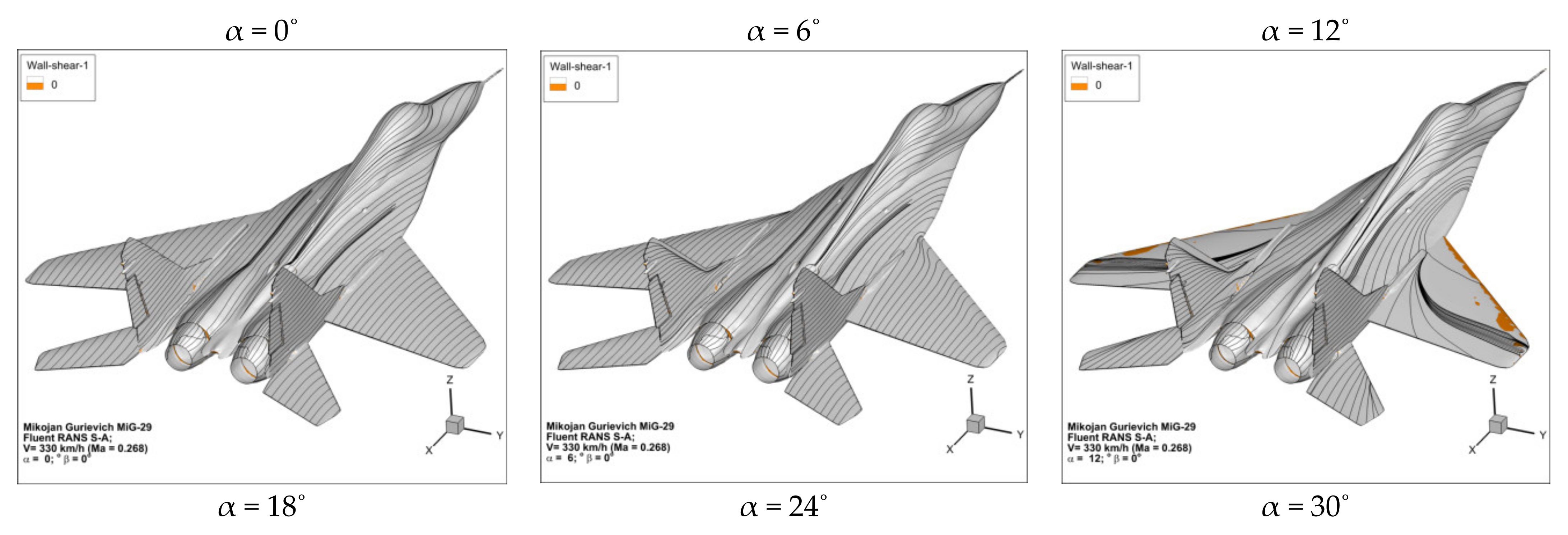
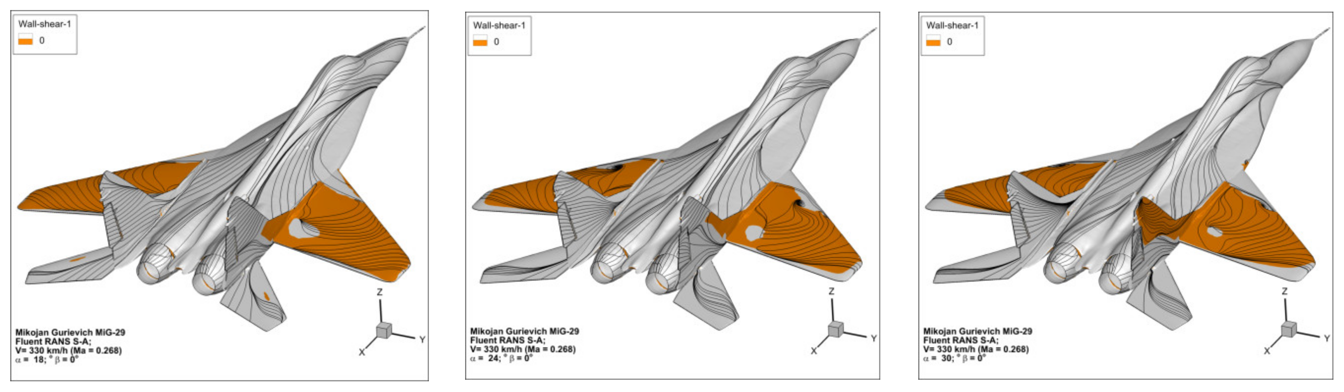
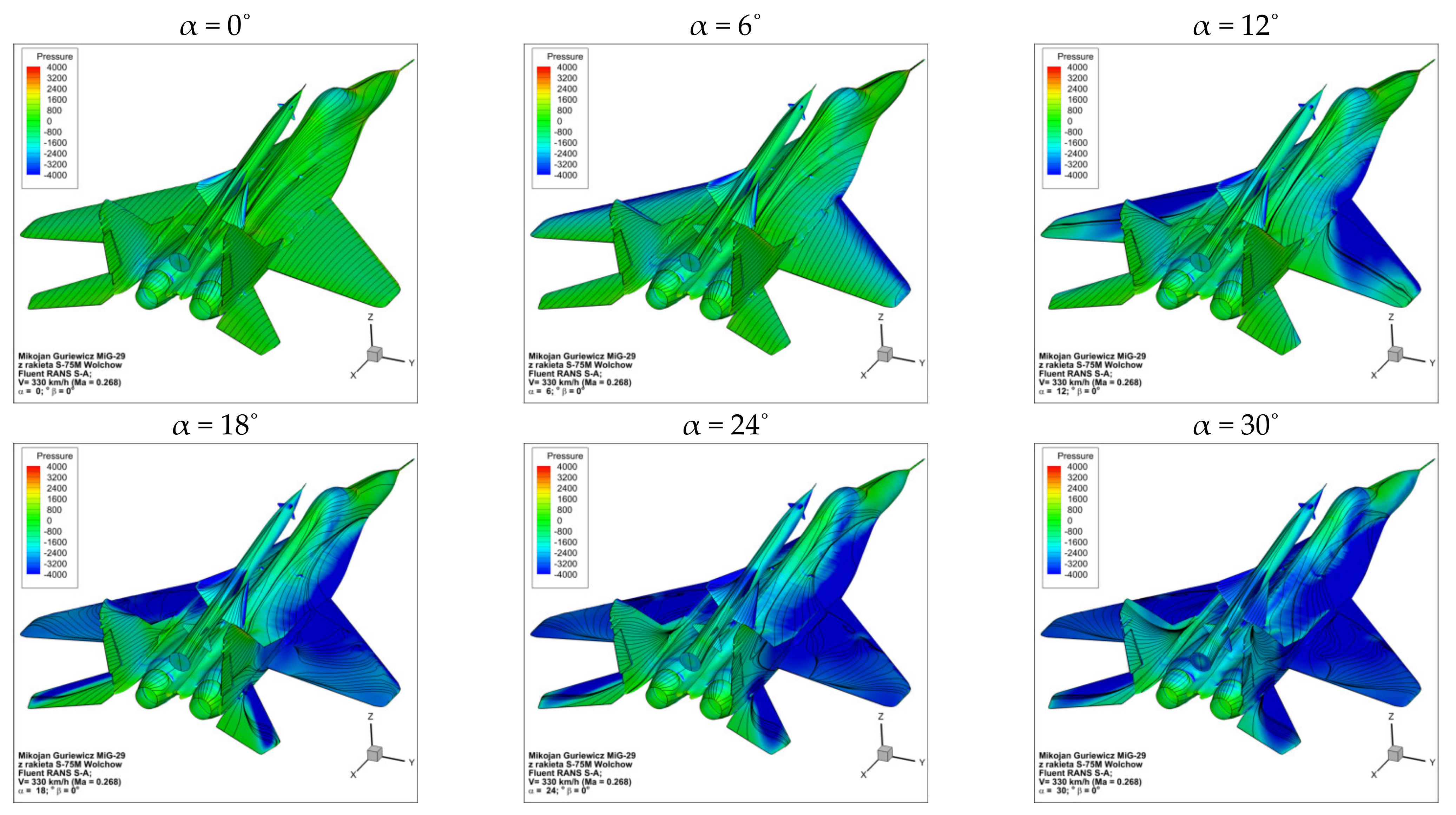
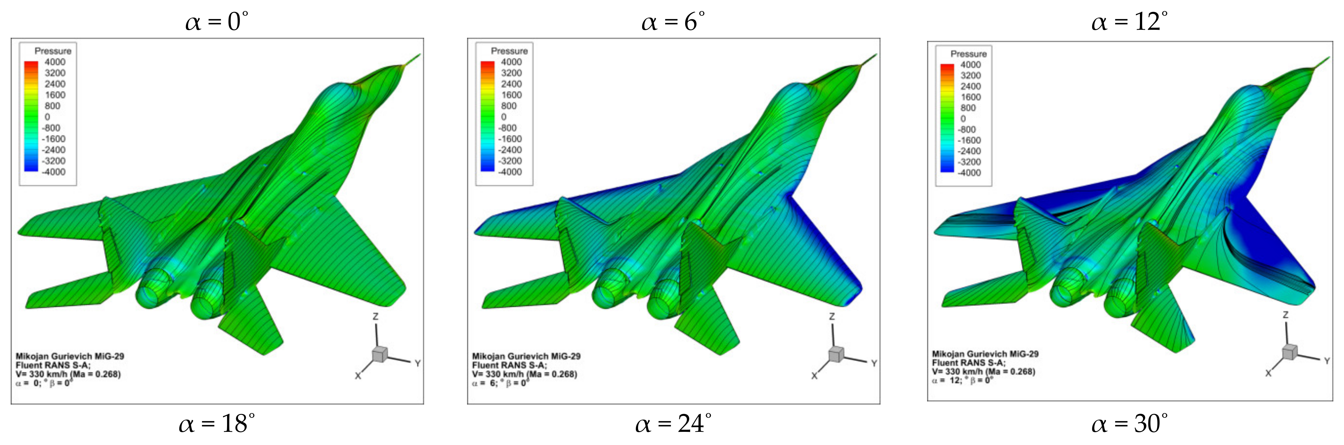
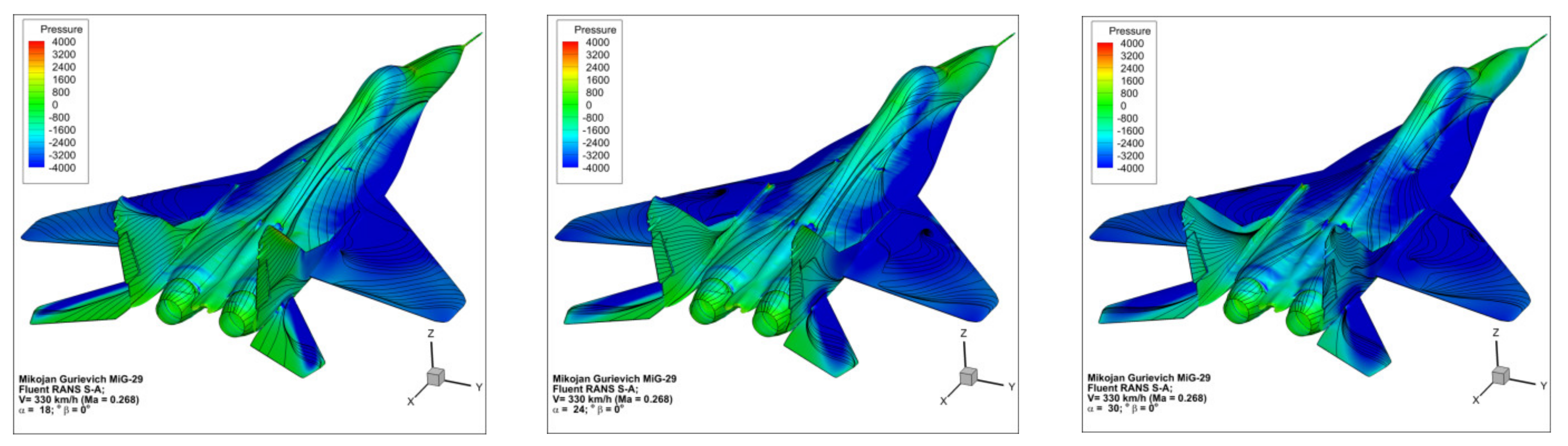
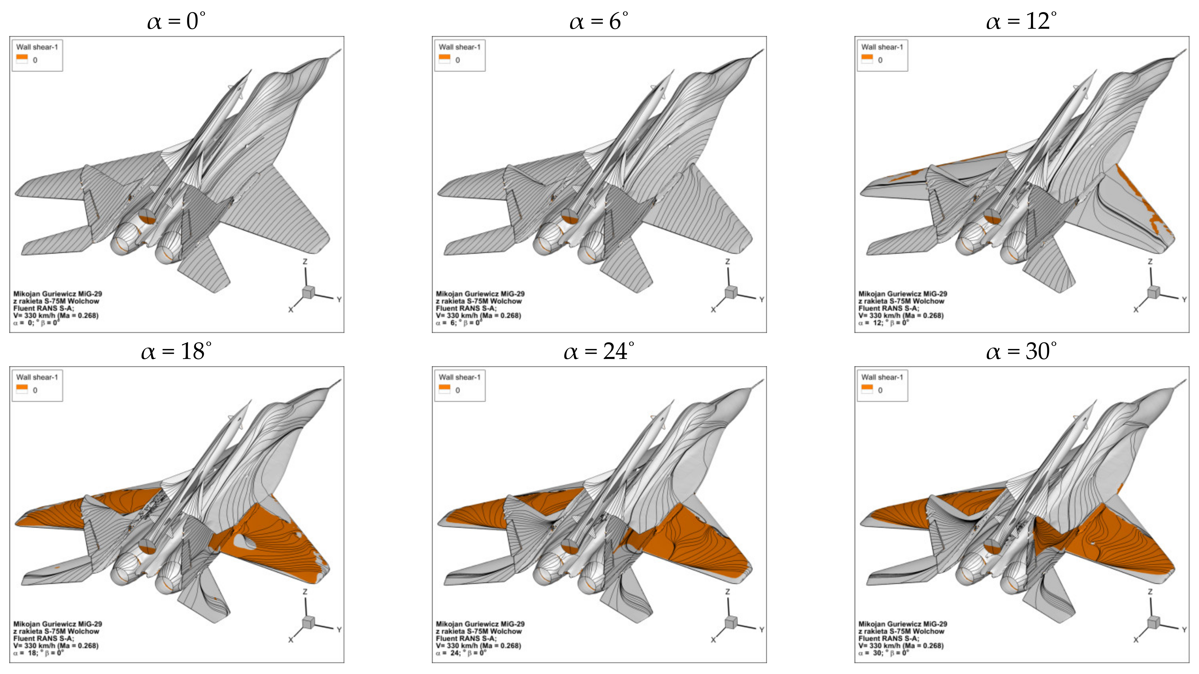
3.2. Qualitative Results

Figure 12 and Figure 13 present a qualitative comparison of the results obtained for selected angles of attack in the form of a pressure map with path lines shown on the surface of the aircraft with and without the space rocket. Conversely, Figure 14 and Figure 15 show a visualization of the flow separation process on the analyzed objects. The areas of separation, i.e., the areas of reverse flow, were depicted using the friction coefficient component along the aircraft axis. The coloring areas were trimmed so as to color only the surfaces where the flow is in the opposite direction to the undisturbed flow. The formation of such areas indicates flow separation, but one must be careful when drawing conclusions because areas of reverse flow also arise around windward impact points, which, on lifting surfaces at high angles of attack, can move far to the back of the airfoil.
It can be seen in the presented drawings that as the angle of attack increases, the negative pressure area on the upper surface of the wing increases. For smaller angles of attack, the negative pressure area is formed at the leading edge of the wings. As the angle of attack increases, the negative pressure area on the wing, air inflow and fuselage surfaces gradually increases. Conversely, the separation of flow begins at the tip of the wing, which is characteristic of a swept wing. As the angle of attack increases, the separation area expands to cover the entire wing. Due to the aerodynamic configuration comprising the lift-generating fuselage, a large critical angle of attack, αkr = 34°, was obtained.
It can be seen in Figure 14 and Figure 15 that below the critical angle of attack, even if separation has already occurred on the wing, airflow is still attached to the upper surface of the fuselage. After analyzing the direction of the path lines on the fuselage surface, it should be stated that this is due to the appropriate shape of the fuselage surface and the leading edge’s extension. In the presented range of the angles of attack, no separation was found on the surface of the tailplane.
Comparing Figure 12 and Figure 13, it is visible that the rocket has marginal influence on the distribution of pressure along its carrier airframe. As Figure 14 and Figure 15 are compared, the only visible influence is a more prominent area of vortex flow on the wing near the stall fences, which are positioned in front of the vertical tail surfaces. This causes the areas of undetached flow on the wing part to appear, where the flaps are usually placed. Since the difference is most prominent at the angles of attack α = 24°–30°—and no one will allow for such an angle of attack in a rocket carrier mission, and, also, the stall fences’ influence here is negligible—the rocket has minimal influence on the stall characteristics of such a complex airframe.
In the whole range of angles of attack studied, no large value of the stream inflow angle was observed on the space rocket’s fuselage or elevons. Alternatively, the wings of the rocket show some relationship between the flow around the structure and the angle of attack. With negative angles of attack on the lower airfoils (near the fuselage), the impact line moves to around 10% of the chord line. For most of the cruise speed angles of attack α = −12°–28°, an image of the vortex moving from the leading edge appears on the surface of the rocket wing. It is a stable vortex, indicating the proper operation of the wing and the tendencies of the rocket to move away from the carrier after its release from the locks. These vortices disappear above the angle of attack α = 34°, when the aircraft flies with full separation.

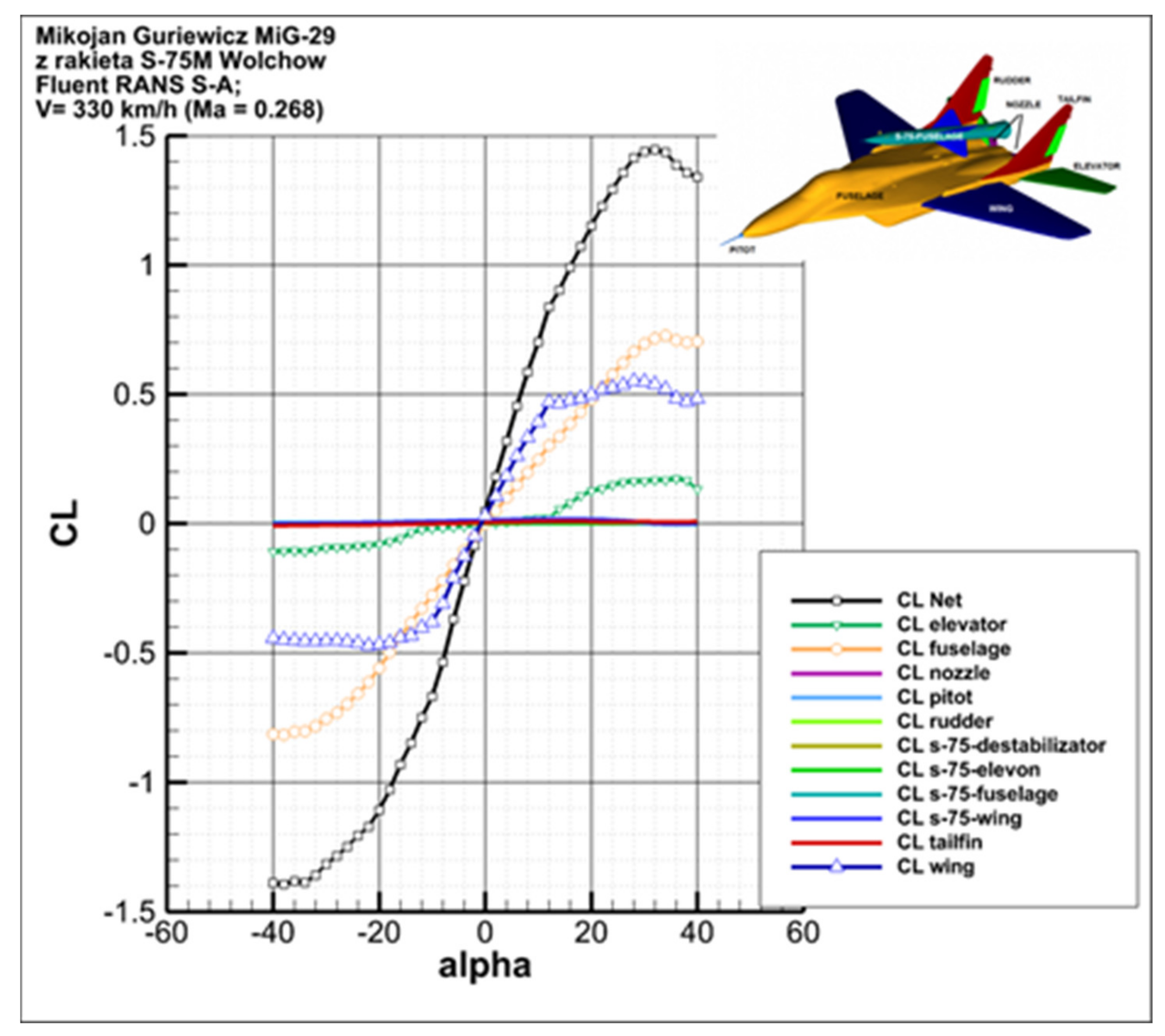
3.3. Analysis of the Impact of Structural Parts of the Aircraft with Space Rocket on the Obtained Aerodynamic Characteristics

Figure 16, Figure 17 and Figure 18 show the impact of components of the carrier aircraft’s airframe and the space rocket on the values of the individual aerodynamic coefficients. In the case of the drag coefficient (Figure 16), in the range of attack angles α = −12°–12°, the main sources of drag are the wing and the fuselage. The share of the airfoil, fuselage and tailplane in the total value of the drag coefficient increases with the increase in the absolute value of the angle of attack. The share of the lifting surface and the fuselage in the total value of the lift coefficient is large (in total, it accounts for almost 90% up to the angle of attack α = 12°). The stall on the wing begins already at the angle of attack α = 12°, and then the influence of the tailplane begins to appear. However, for an angle of attack greater than α = 20°, the aerodynamic lift generated on the fuselage is greater than that on the wing. Furthermore, the share of the tailplane in the value of the lift coefficient significantly increases above the angle of attack α = 20° and reaches almost 20% for α = 32°. Conversely, from the characteristics of the pitching moment coefficient (Figure 18), one can read the stability-decreasing impact of the aircraft’s fuselage and the much greater stability-increasing impact of the tailplane and the wing of the aircraft.
Figure 19 presents pie charts showing the percentage share of structural parts of carrier aircraft with space rockets in the drag force total value for the angles of attack α = 0° and α = 4°, respectively. With the increase in the angle of attack, an increase in the percentage share of the wing, fuselage and elevator in the total value of the drag force was noted. For example, for a wing, this value changes from 13.5% to 14.6%. Even greater changes were obtained for a fuselage, where it changes from 33.5% to 38%. This is related to an increase in the value of the induced drag. However, the exact opposite situation can be observed for the other structural parts.
The presented results confirm the negligible impact of the space rocket on the aerodynamic characteristics of the carrier aircraft. In addition, this is evidence of the correct selection of the location of the rocket relative to the aircraft’s airframe.

4. Conclusions

In the course of the research work, a number of numerical aerodynamic analyses of the low-cost satellite launch system were carried out. Numerical analyses were performed using the finite volume method, specialized software and a high-performance computing cluster. Both quantitative and qualitative results were obtained. The values of drag and aerodynamic lift, as well as the pitching moment, as a function of the angle of attack for the analyzed configurations of the carrier aircraft, were determined. For the selected flight conditions of the aircraft, pressure maps with path lines on the airframe’s surface were determined and areas of flow separation, i.e., areas of reverse flow on its surface, were presented. The obtained results will have a significant impact on the decisions of the research team regarding the final shape of the low-cost satellite launch system being developed. In addition, the resulting aerodynamic characteristics can be used during the stage of determining loads that act on the structure of the aircraft during the flight and to determine conditions for safe separation of the aircraft and the rocket. Based on the analysis of the obtained results, the following conclusions were drawn:
The presence of the carried space rocket does not significantly affect the flow field on or around the aircraft and does not cause any degeneration of vortices generated by the leading edge’s extension;
The impact of the space rocket on the change in aerodynamic characteristics of the carrier aircraft is negligible;
The space rocket was correctly positioned relative to the airframe of the carrier aircraft;
The shape of the carrier aircraft’s fuselage in connection with the leading edge’s extension has a significant impact on the value of the critical angle of attack;
The influence of the leading edge’s extension on the aerodynamic characteristics of the aircraft was observed.
The high comparability between the results of the numerical analyses and the results of experimental tests indicates the correctness of the adopted research methodology.

Author Contributions

Conceptualization, A.O., P.Z. and Ł.K.; methodology, A.O. and A.D.; validation, A.O. and Ł.K.; formal analysis, A.O.; investigation, A.D.; resources, P.Z. and Ł.K.; writing—original draft preparation, A.D. and Ł.K.; writing—review and editing, Ł.K.; visualization, A.D.; supervision, P.Z.; funding acquisition, A.O. and P.Z. All authors have read and agreed to the published version of the manuscript.

Funding

The paper was elaborated based on data obtained during the research carried out during the following project: Aerial Rocket Launch System to Low Earth Orbit—Feasibility Study—GB MON/13-989/2018/WAT—funded by the Ministry of National Defense; that was implemented in the Military University of Technology.

Institutional Review Board Statement

Not applicable.

Informed Consent Statement

Not applicable.

Data Availability Statement

The data presented in this study are available on request from the corresponding author.

Conflicts of Interest

The authors declare no conflict of interest.

References

  1. Jones, H.W. The recent large reduction in space launch cost. In Proceedings of the 48th International Conference on Environmental Systems ICES-2018-81, Albuquerque, NM, USA, 8–12 July 2018; Available online: https://ttu-ir.tdl.org/bitstream/handle/2346/74082/ICES_2018_81.pdf?sequence=1&isAllowed=y (accessed on 1 March 2022).
  2. Almazrouei, A.; Khan, A.; Almesmari, A.; Albuainain, A.; Bushlaibi, A.; Al Mahmood, A.; Alqaraan, A.; Alhammadi, A.; AlBalooshi, A.; Khater, A.; et al. A Complete Mission Concept Design and Analysis of the Student-Led CubeSat Project: Light-1. Aerospace 2021, 8, 247. [Google Scholar] [CrossRef]
  3. Orbital, A.T.K. Pegasus User’s Guide; Orbital ATK: Dulles, VA, USA, 2015. [Google Scholar]
  4. Chen, T.; Ferguson, P.W.; Deamer, D.A.; Hensley, J. Responsive Air Lunch F-15 Global Strike Eagle. In Proceedings of the AIAA—Proceedings of 4th Responsive Space Conference, Los Angeles, CA, USA, 24–27 April 2006. [Google Scholar]
  5. Clarke, J.P.; Cerven, K.; March, J.; Olszewski, M.; Wheaton, B.; Williams, M.; Yu, J.; Selig, M.; Loth, E.; Burton, R. Conceptual Design of a Supersonic Air-launch System. In Proceedings of the 43rd AIAA/ASME/SAE/ASEE Joint Propulsion Conference & Exhibit AIAA, Cincinnati, OH, USA, 8–11 July 2007. [Google Scholar]
  6. Bartolotta, P.A. Horizontal Launch: Versatile Concept for Assured Space Access; NASA: Pasadena, CA, USA, 2011.
  7. DARPA. Report on Horizontal Launch Study; The Defense Advanced Research Projects Agency: Arlington, VA, USA, 2011.
  8. Kesteren, M.W. Air Launch versus Ground Launch: A Multidisciplinary Design Optimization Study of Expendable Launch Vehicles on Cost and Performance, Faculty of Aerospace Engineering; Delft University of Technology: Delft, The Netherlands, 2013. [Google Scholar]
  9. Niederstrasser, C. Small Launch Vehicles—A 2018 State of the Industry Survey. In Proceedings of the 32nd Annual AIAA/USU Conference on Small Satellites, Logan, UT, USA, 4–9 August 2018. [Google Scholar]
  10. Lopata, J.; Rutan, B. RASCAL: A Demonstration of Operationally Responsive Space Launch. In Proceedings of the AIAA-Proceedings of the 2nd Responsive Space Conference, San Diego, CA, USA, 28–30 September 2004. [Google Scholar]
  11. Smolyakov, A.V.; Yanakaev, V.A.; Kornev, A.V.; Shevko, S.V. “MARKS” Small Aviation-Rocket Space Launch System. J. Eng. Sci. Technol. 2018, 13, 1143–1152. [Google Scholar]
  12. Olejnik, A.; Dobrzyński, P.; Machowski, B.; Zalewski, P. Concept of Airborne Rocket System of Mini- and Micro-satellites Launching. Mechanik 2018, 7, 511–513. (In Polish) [Google Scholar]
  13. ANSYS. Fluent Theory Guide; Version 15.0; Ansys Inc.: Canonsburg, PA, USA, 2013. [Google Scholar]
  14. Tomaszewski, A.; Goraj, Z. Assessment of a small UAV speed polar graph by conducting flight tests. Aircr. Eng. Aerosp. Technol. 2018, 91, 1–8. [Google Scholar] [CrossRef]
  15. Górniak, C.; Goraj, Z.; Olszański, B. Research and selection of MALE wing profile. Aircr. Eng. Aerosp. Technol. 2018, 91, 264–271. [Google Scholar] [CrossRef]
  16. Klimczyk, W.A.; Goraj, Z. Analysis and optimization of morphing wing aerodynamics. Aircr. Eng. Aerosp. Technol. 2018, 91, 538–546. [Google Scholar] [CrossRef]
  17. Rodzewicz, M.; Goraj, Z.; Tomaszewski, A. Design and testing of three tailless unmanned aerial vehicle configurations built for surveillance in Antarctic environment. Proc. Instit. Mech. Eng. Part G—J. Aerosp. Eng. 2018, 232, 2598–2614. [Google Scholar] [CrossRef]
  18. Wojewodka, M.; White, C.; Shahpar, S.; Kontis, K. Numerical study of complex flow physics and coherent structures of the flow through a convoluted duct. Aerosp. Sci. Technol. 2022, 121, 107191, ISSN 1270-9638. [Google Scholar] [CrossRef]
  19. Olejnik, A.; Kiszkowiak, Ł.; Dziubiński, A. Aerodynamic modeling process using Reverse Engineering and Computational Fluid Dynamics. In Earth and Space 2018: Engineering for Extreme Environments; American Society of Civil Engineers: Reston, VA, USA, 2018; pp. 944–956. ISBN 9780784481899. [Google Scholar] [CrossRef]
  20. Olejnik, A.; Kachel, S.; Leszczyński, P.; Łącki, T. Development of MiG-29 Aircraft Geometric Model Based on Surface Scanning. Mechanik 2010, 7, 337–348. (In Polish) [Google Scholar]
  21. Hirsch, C.H. Numerical Computation of Internal and External Flows: The Fundamentals of Computational Fluid Dynamics, 2nd ed.; Butterworth-Heinemann: Woburn, MA, USA, 2007; ISBN 9780750665940. [Google Scholar]
  22. ANSYS ICEM CFD Tutorial Manual, Ansys ICEM CFD 15; ANSYS, Inc.: Canonsburg, PA, USA, 2013.
  23. PN-ISO 1151-1; Flight Dynamics: Constants and Symbols—Part 1: The Movement of Aircraft in Air. Polish Comittee for Standardisation: Warsaw, Poland, 2004. (In Polish)
  24. Sobieraj, W. Aerodynamics; Military University of Technology: Warsaw, Poland, 2014. (In Polish) [Google Scholar]
  25. Dziubiński, A.; Jaśkowski, P.; Seredyn, T. CFD Analysis of Agricultural Aircraft Aerodynamic Characteristics. Trans. Inst. Aviat. 2016, 4, 321–337. [Google Scholar] [CrossRef]
  26. Krzyżanowski, A.; Chlebny, B.; Wojciechowski, Z. Experimental Characteristics of a MiG-29 Aircraft Model with Strakes; Military University of Technology: Warsaw, Poland, 1994. (In Polish) [Google Scholar]
Figure 1. Partial measurement results regarding the wing, fuselage and tail sections.
Aerospace 09 00284 g001
Figure 2. Coordinate systems, transition angles and components of aerodynamic force and moment. (Blue color shows the coordinate system, in which the results are presented.)
Aerospace 09 00284 g002
Figure 3. Computational domain.
Aerospace 09 00284 g003
Figure 4. Computational mesh density on the carrier aircraft in configuration with the space rocket.
Aerospace 09 00284 g004
Figure 5. The cases of different densities (and sizes) for mesh: (a) 0.15 million cells, (b) 0.34 million cells, (c) 1 million cells, (d) 5 million cells. The third one (c) was selected for further studies.
Aerospace 09 00284 g005
Figure 6. Approximation error and calculation time as a function of mesh size.
Aerospace 09 00284 g006
Figure 7. Division of the aircraft airframe and rocket surfaces into appropriate computational zones.
Aerospace 09 00284 g007
Figure 8. Comparison of aerodynamic drag characteristics of carrier aircraft with and without the space rocket.
Aerospace 09 00284 g008
Figure 9. Comparison of aerodynamic lift characteristics of carrier aircraft with and without the space rocket.
Aerospace 09 00284 g009
Figure 10. Comparison of pitching moment characteristics of carrier aircraft with and without the space rocket.
Aerospace 09 00284 g010
Figure 11. Comparison of aerodynamic efficiency characteristics of carrier aircraft with and without the space rocket.
Aerospace 09 00284 g011
Figure 12. Presentation of changes in the pattern of path lines on the surface of the aircraft in the configuration with the space rocket together with a visualization of the pressure distribution for various values of the angle of attack.
Aerospace 09 00284 g012
Figure 13. Presentation of changes in the pattern of path lines on the surface of the aircraft in the configuration without the space rocket together with a visualization of the pressure distribution for various values of the angle of attack.
Aerospace 09 00284 g013aAerospace 09 00284 g013b
Figure 14. Presentation of changes in the pattern of path lines on the surface of the aircraft in the configuration with the space rocket together with a visualization of the separation areas for various values of the angle of attack.
Aerospace 09 00284 g014
Figure 15. Presentation of changes in the pattern of path lines on the surface of the aircraft in the configuration without the space rocket together with a visualization of the separation areas for various values of the angle of attack.
Aerospace 09 00284 g015aAerospace 09 00284 g015b
Figure 16. Components of the aerodynamic drag coefficient as a function of the angle of attack for individual division zones of the geometry of the airframe of the aircraft and the space rocket.
Aerospace 09 00284 g016
Figure 17. Components of the aerodynamic lift coefficient as a function of the angle of attack for individual division zones of the geometry of the airframe of the aircraft and the space rocket.
Aerospace 09 00284 g017
Figure 18. Components of the aerodynamic moment coefficient as a function of the angle of attack for individual division zones of the geometry of the airframe of the aircraft and the space rocket.
Aerospace 09 00284 g018
Figure 19. Percentage share of structural parts of aircraft with space rocket in drag force total value for angles of attack α = 0° and α = 4°.
Aerospace 09 00284 g019
Publisher’s Note: MDPI stays neutral with regard to jurisdictional claims in published maps and institutional affiliations.

