Article

Experimental Investigation of a Cylindrical Air-Breathing Continuous Rotating Detonation Engine with Different Nozzle Throat Diameters

College of Aerospace Science and Technology, National University of Defense Technology, Changsha 410073, China
*
Authors to whom correspondence should be addressed.
Aerospace 2022, 9(5), 267; https://doi.org/10.3390/aerospace9050267
Submission received: 29 March 2022 / Revised: 5 May 2022 / Accepted: 9 May 2022 / Published: 16 May 2022
(This article belongs to the Section Astronautics & Space Science)

Abstract

:
A continuous detonation engine with various exhaust nozzles, analogous to typical scramjet cavity combustors with variable rear-wall heights, was adopted to perform a succession of cylindrical air-breathing continuous rotating detonation experiments fueled by a non-premixed ethylene/air mixture. The results show that the detonation combustion was observed to self-sustain in the combustor through simultaneous high-speed imaging covering the combustor and isolator. A long test, lasting more than three seconds, was performed in this unique configuration, indicating that the cylindrical isolator–combustor engine exhibits potential for practical applications. Three distinct combustion modes were revealed with varied equivalent ratios (hybrid mode, sawtooth wave mode, and deflagration mode). The diameter of the nozzle throat was critical in the formation of rotating detonation waves. When the nozzle throat diameter was larger than the specific value, the detonation wave could not form and self-sustain. The upstream boundary of the shock train was supposed to be close to the isolator entrance in conditions of a high equivalence ratio and small nozzle throat diameter. In addition, it was verified that periodic high-frequency pressure oscillation could cause substantial impacts on the incoming flow as compared with the steady deflagration with the same combustor pressure.

1. Introduction

Detonation combustion can be approximately viewed as constant volume combustion with considerable pressure gain, as compared with constant pressure combustion. The pressure-gain detonation combustion system with higher thermodynamic efficiency is expected to be applied to aerospace propulsion systems to enhance thrust performance. Detonation engines can generally be classified into pulse detonation engines [1], continuous rotating detonation (CRD) engines [2], and oblique detonation engines [3]. CRD engines have received increasing attention due to their clear advantages in simple combustor geometry, single ignition, and stable thrust. A typical CRD engine can use a co-axial annular combustor or a cylindrical combustor. Once ignited, one or multiple rotating detonation waves circumferentially propagate in the combustor whilst continuously injecting propellant, producing a roughly steady thrust without any interval.
An air-breathing CRD engine is one such application of rotating detonation. Braun et al. [2] reported a cycle analysis model and demonstrated that an air-breathing CRD fueled by a hydrogen/air mixture could operate stably within Ma 1.5–5. Zhdan et al. [4] established an unsteady two-dimensional mathematical model and found that the CRD could be achieved with an upper limit of Ma 3. Dubrovskii et al. [5] conducted a three-dimensional numerical simulation of an air-breathing CRD engine fueled by a hydrogen/air mixture and verified the feasibility of the CRD engine under flight conditions of Ma 5.0 and an altitude of 20 km. Smirnov et al. [6,7] investigated a hydrogen/oxygen CRD through three-dimensional numerical simulations and found that the stability of the rotating detonation waves was related to the combustor width and oxygen concentration. Wu et al. [8] focused on the flow field of an air-breathing CRD engine and examined its influence on stability through the three-dimensional numerical simulation. Wang et al. experimentally illustrated the feasibility of an air-breathing CRD fueled by hydrogen/air via a direct-connect test [9] and obtained four distinct propagation modes under different operating conditions [10]. Liu et al. [11] realized an air-breathing CRD powered by hydrogen/air in a free jet and argued that the nozzle contraction ratio is crucial for the combustor pressure and propulsive performance. Frolov et al. [12] conducted a series of air-breathing CRD engine experiments in a wind tunnel and verified that the CRD could self-sustain in hypersonic inflow conditions. Meng et al. [13] experimentally obtained an air-breathing liquid-kerosene-air rotating detonations wave via a direct-connect facility under Mach 4 flight conditions and found that the detonation wave is located downstream of the cavity, owing to the characteristic distance required for the evaporation and mixing of liquid kerosene. Prior investigations have established that an air-breathing CRD engine exhibits potential for practical applications.
Except for the annular combustor, numerous studies related to hollow combustors were recently carried out. Tang et al. [14] found that the detonation behaviors were similar in the hollow combustor and annular through three-dimensional numerical simulations. Zhang et al. [15] found that the CRD wave was more accessible to form in a hollow combustor than in an annular combustor. Peng et al. [16] demonstrated the realization of hydrogen/air, ethylene/air, and methane/air CRD waves in a hollow combustor and demonstrated that the large combustor width and recirculation zone had a significant effect on the CRD realization. Yokoo et al. [17] found that the combustor length did not have a great influence on the detonation wave propagation velocity and thrust performance in the hollow combustor. Recently, Gejji et al. [18] achieved a premixed natural gas/air CRD in a cylindrical air-breathing engine configuration, with a CRD wave propagation speed reaching 79.9–89.7% of the CJ detonation velocity. To further simplify the air-breathing CRD engine structure and reduce the weight, a cylindrical isolator–combustor combination for the air-breathing CRD engine was proposed by Wang et al. [19]; non-premixed ethylene/air CRD was realized under the inflow with Ma 2. These experimental results demonstrated the potential of this cylindrical air-breathing CRD engine for propulsion applications.
In an air-breathing engine, the effect of backpressure on inflow is critical, which has been extensively investigated in scramjet. Huang et al. [20] discussed the impacts of the isolator divergent angle and the backpressure on the location of the leading edge of the shock train through three-dimensional numerical simulations. Su et al. [21] found that the dynamic backpressure has a significant effect on the position of the pseudo shock leading edge. The amplitudes of the dynamic backpressures had a substantial impact on the maximum upstream and downstream locations of the pseudo shock leading edge. In the rocket mode of the CRD engine, the interaction of the CRD wave with the inflow was discussed. Peng et al. [16] found that the CRD wave propagated upstream through the oblique shock wave, and the angle of the oblique shock wave varied depending on the fuel type. Rankin et al. [22] observed that the high-pressure detonation wave could inhibit the inflow of the fuel during the purging period. However, the mechanisms of the CRD wave interacting with supersonic inflow in the air-breathing mode have not fully been clarified.
This study investigated the effect of the exhaust nozzle in a cylindrical air-breathing CRD engine. A series of direct-connect tests propelled by non-premixed vitiated air/ethylene was conducted with various exhaust nozzle diameters. Three distinct combustion modes were identified in different operating conditions. The self-sustaining location of the rotating detonation wave was directly observed. Additionally, the effects of the nozzle throat diameter on CRD realization, combustion mode shift, and the impact of an induced oblique shock wave on inflow were investigated.

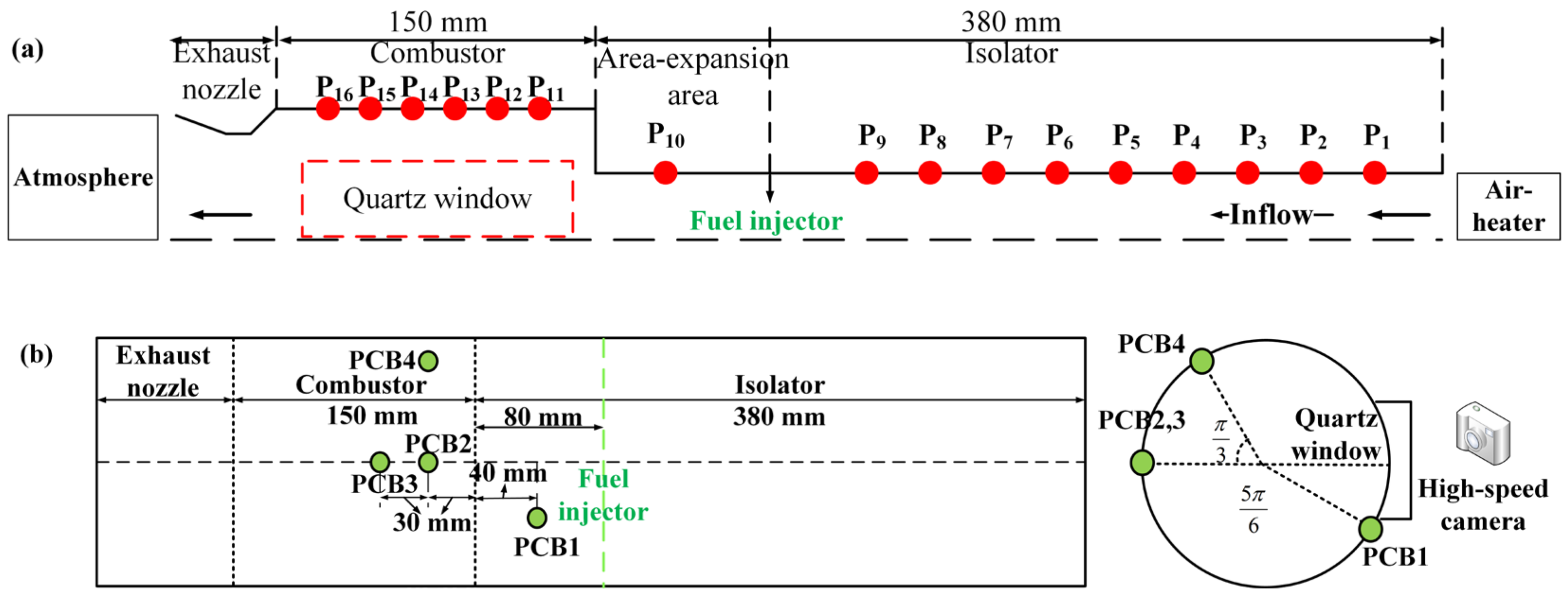
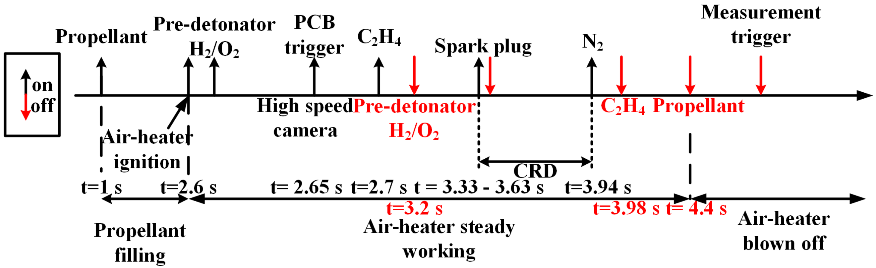
2. Experimental Section

In this study, tests were performed on a direct-connected facility composed of an air heater and a Laval nozzle, as reported in Reference [23]. In the air heater, a vitiated high-enthalpy airflow was created through the combustion of oxygen and pure ethyl alcohol. Propellants were burned to heat the air from room temperature to 860 K, whereby the pressure of the air-heater combustor increased to 0.44 MPa. After the acceleration of the Laval nozzle, the vitiated air reached a velocity of Ma 2.
The cylindrical isolator–combustor is illustrated in Figure 1. The diameter and length of the isolator were 56 mm and 380 mm, respectively. The length of the combustor was 150 mm, with a diameter of 112 mm. The combustor with the exhaust nozzle was analogous to the scramjet cavity-based combustor (depth = 56 mm, length/depth = 5.37). The ethylene was directly injected into the airflow via 60 injection holes with diameters of 0.5 mm that are uniformly distributed circumferentially. The axis position of the injection hole was 80 mm upstream from the combustor entrance. The diameter of the exhaust nozzle (Dexh) varied from 68 mm to 80 mm, with a 2 mm spacing. A hot tube was used for detonation initiation, directly connected to the hollow combustor. An ordinary spark plug ignited the premixed hydrogen/oxygen mixture in the hot tube. With a Schelkin spiral in the pre-detonator, the detonation wave was formed through a deflagration to detonation transition (DDT) and propagated into the combustor to induce the combustible mixture.
In the test, the absolute pressures of plenums and supply pipes were measured by piezo-resistance sensors (Model MPM480, range: 0–5 MPa) at a sampling frequency of 500 Hz. In addition, the wall pressure along the streamwise direction was measured by the pressure transducers (Model MPM282, range: 0–700 kPa) at a sampling rate of 200 Hz, with a measurement error of less than 0.5% at full scale (measurement error ±3.5 kPa). A PCB sensor (Model 113B24) was adopted in the NI sampling system to measure and record the high-frequency dynamic pressure. The sampling frequency was 2 MHz with a sampling interval of 0.5 μs. The sensitivity of the PCB sensor was 0.725 mV/kPa, with a resolution of 0.035 kPa. The installation positions of the PCB sensors are labeled in Figure 1b. The PCB2_0deg_30 mm and PCB4_60deg_30 mm were arranged at the same axial location with a circumferential angle of 60°, 30 mm downstream from the combustor entrance.
Except for pressure measurements, the Photron Fast Camera SA-X2 (Photron, Tokyo, Japan) high-speed camera (The maximum frame per second is 1,080,000 at the resolution of 128 × 8) was used to record and visualize the self-luminescence of the reaction zone in the combustor and isolator, as shown in Figure 2. A ring-shaped optical glass with a length of 40 mm was specifically designed to replace the original metallic connecter between the injection and the combustor. The quartz glass was composed of the inner curvature surface and the outer plane surface in the combustor, with rectangular sizes of 95 mm and 45 mm. The high-speed photography images were recorded at an imaging velocity of 45,000 frames per second. The exposure time was set as 1/48,539 s, and the corresponding resolution was 896 × 304 pixels, denoted as x × y pixels. The high-speed camera could simultaneously cover the combustor and isolator to observe the position of the reaction zone.
The time sequence of the experiment is depicted in Figure 3. Pneumatic and electromagnetic valves were installed in the feeding lines in order to rapidly monitor and respond to gas supply changes. In each experiment, the air-heater was designed to work first and supply the necessary inflow conditions. To ensure reliable results, the entire direct-connected CRD test, including detonation initiation, self-sustaining, and quenching, was conducted under stable inflow conditions. When the high total-temperature inflow provided by the air-heater is stabilized, the ethylene valve will be turned on at t = 2.7 s, and ethylene will be injected into the engine model. When a stable pressure platform is established in the fuel plenum, the combustible gas mixture will be ignited by the detonation wave produced by the hot tube at t = 3.33 s. Then, rotating detonation waves formed gradually and propagated steadily. When the preset CRD duration was completed, gaseous nitrogen for extinguishing was fed into the fuel plenum to dilute the remaining ethylene, and the ethylene valve was turned off. Finally, the air-heater was shut off after the combustion had entirely been extinguished.

3. Results and Discussion

A series of experiments was conducted in the vitiated air by varying the nozzle throat diameter and the test conditions. The mass flow rate of vitiated air was set as 1000 g/s, with an equivalent ratio (ER) varying from 0.4 to 1.1. Based on the experimental results, the operating process and range are summarized. Meanwhile, the effects of Dexh on the propagation characteristics of the detonation wave are discussed. Moreover, the impacts of the rotating dynamic backpressure on the supersonic inflow are discussed in detail.

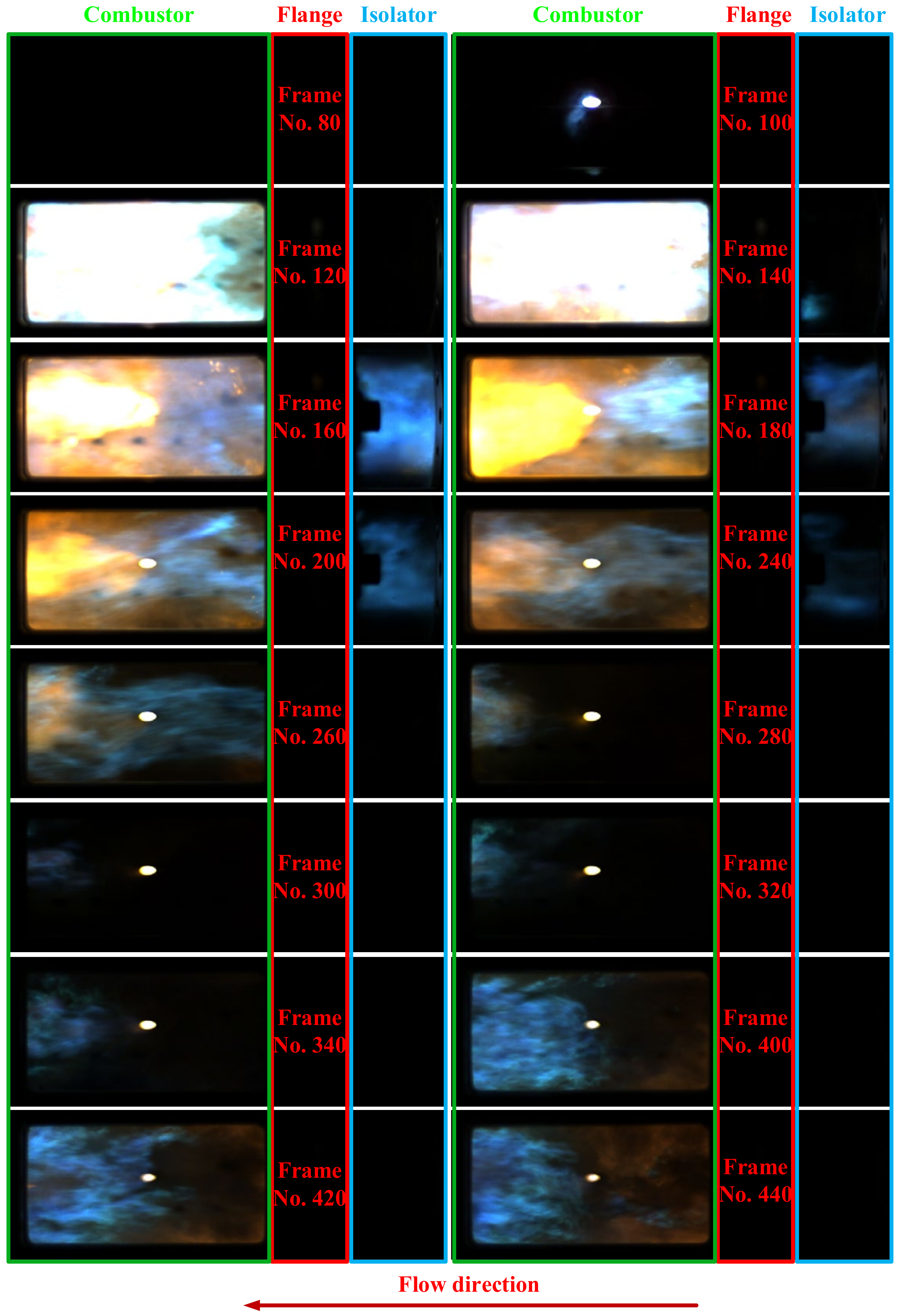
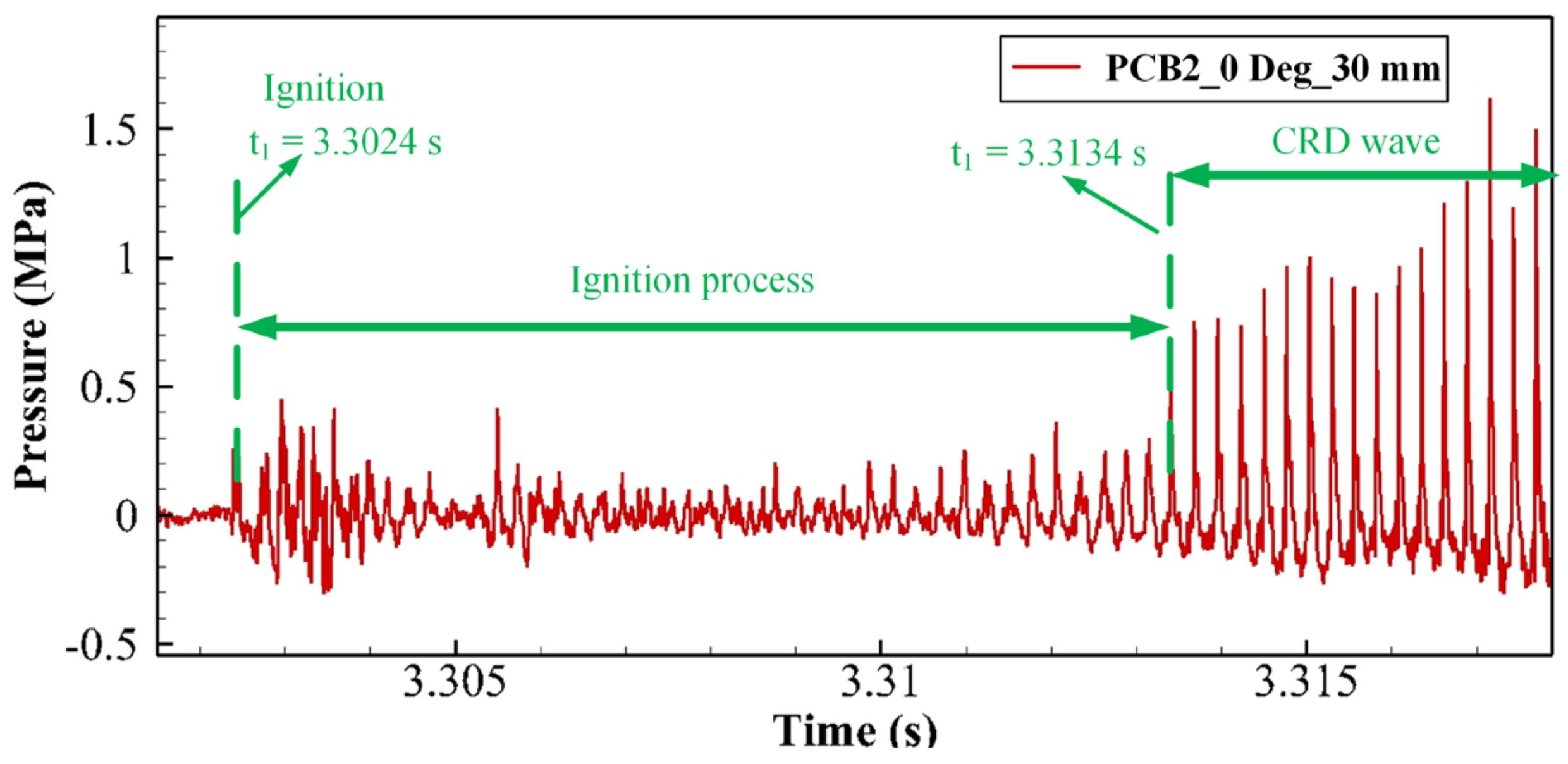
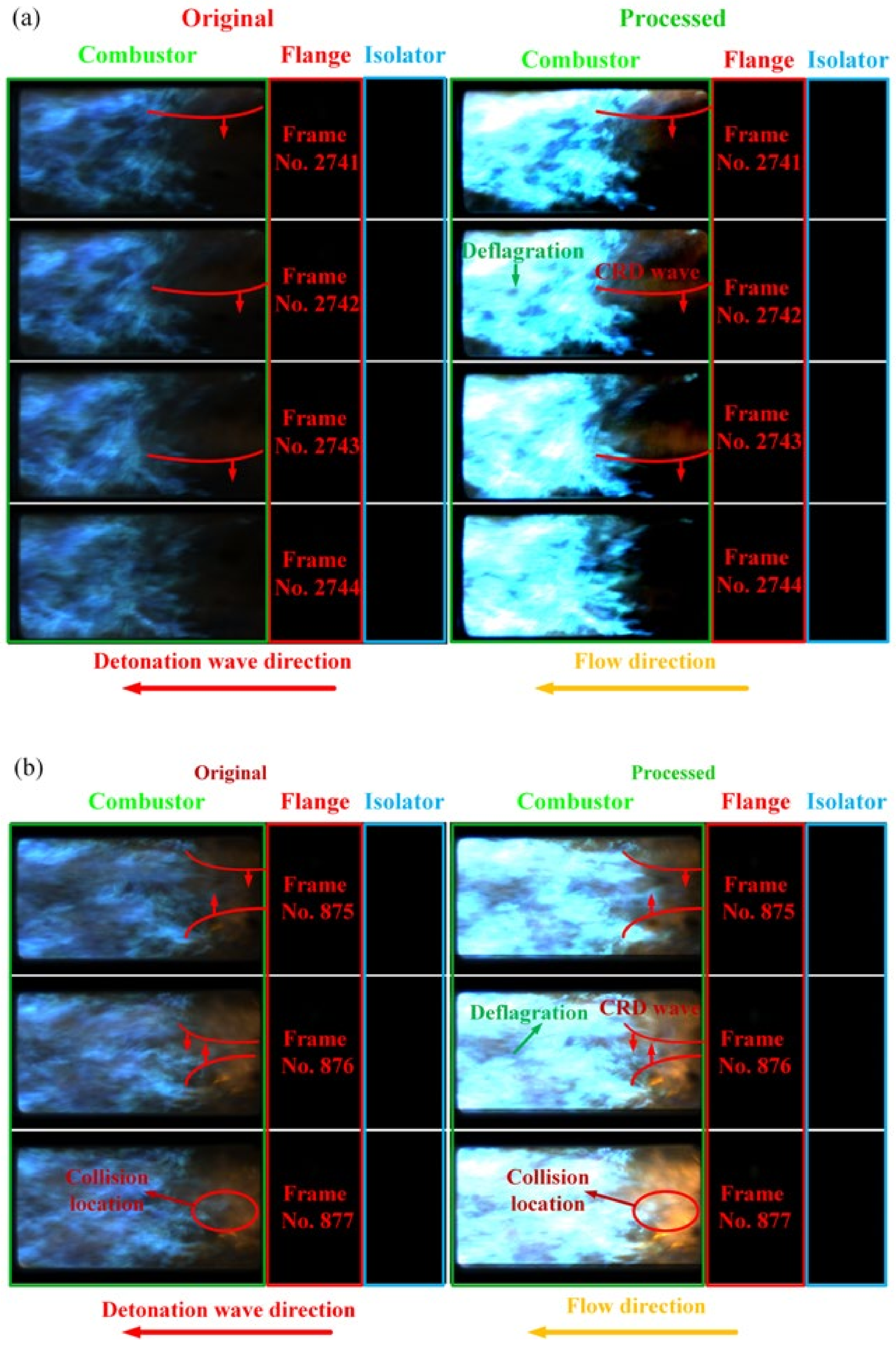
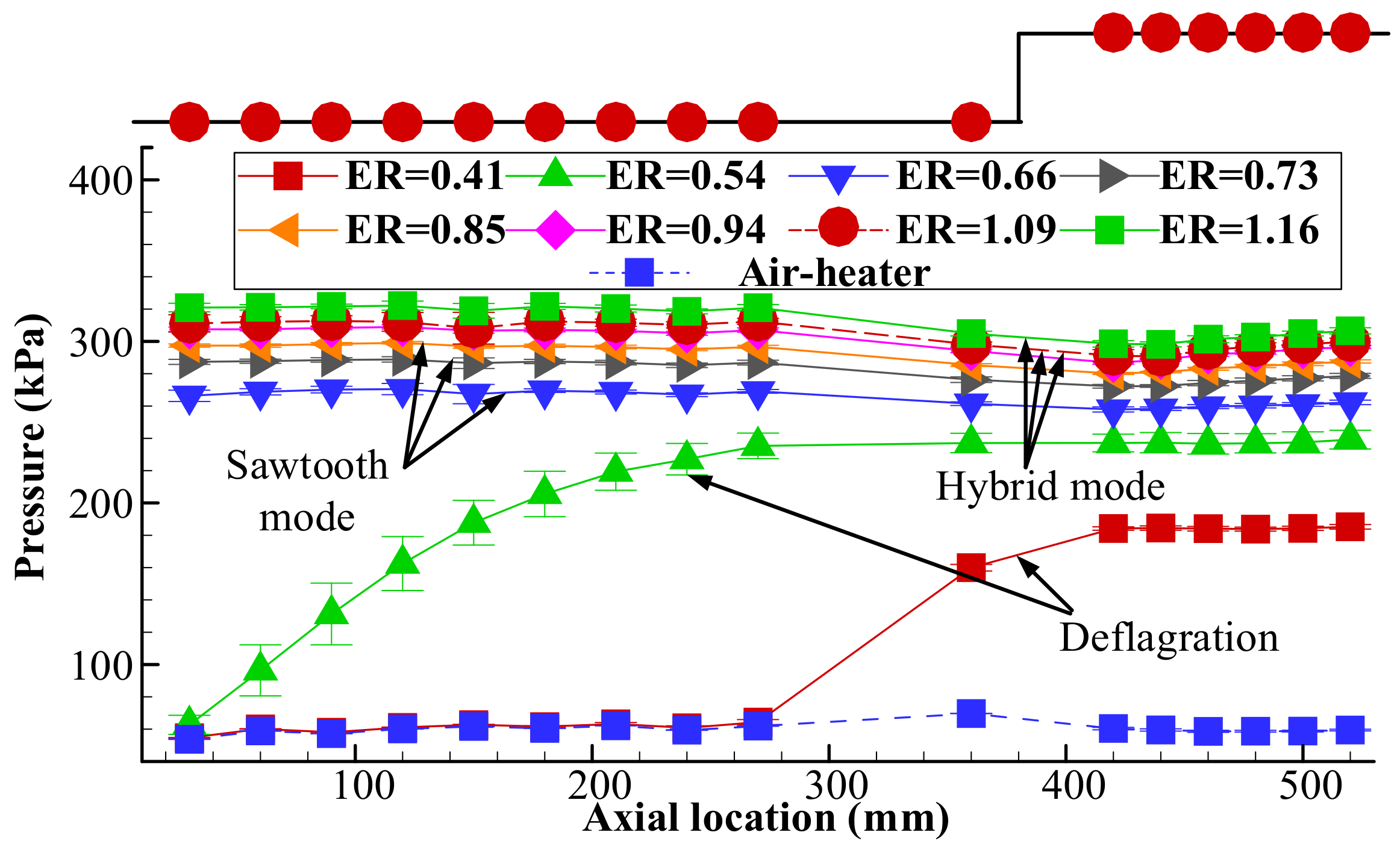
3.1. Analysis of the Detonation Wave Operation Process

The representative operating condition and a summary of the results for the three combustion modes are listed in Table 1 (All experiment conditions have been listed in Appendix A, Table A1). Note that f denotes the dominant frequency of fast Fourier transformation (FFT).
Figure 4 demonstrates the PCB original voltage signal and combustor wall pressure. Figure 4 illustrates the PCB original voltage signal and combustor wall pressure. The combustor pressures increase immediately after the ignition at t = 3.33 s and remain stable through the experimental duration of about 0.6 s for all three combustion modes. Besides, if the PCB sensor is exposed to the high-temperature conditions caused by combustion, the pressure measurement is in an unbalanced negative state, and the original voltage data exhibit a discernible drop and thermal drift due to the accumulation of negligible decline. The combustion duration can also be inferred as 0.6 s, consistent with the combustion duration measured by the static pressure sensor. Figure 5 demonstrates the local view of dynamic high-frequency pressure results for these three typical combustion modes. As shown in Figure 5a, the hybrid mode (HM) meant that the two propagation modes (single wave and counter-rotating two-waves) were involved throughout the whole experiment. For the single wave duration, the pressure peaks traveled in the sequence of “ a 1 b 1 a 2 b 2 ”. Then, the mode shifted into the counter-rotating two-wave mode, with pressure peaks propagating in the sequence of “ a 1 b 1 b 2 a 2 ”. In Figure 5b, the dynamic high-frequency pressure of the sawtooth wave also presents a periodic oscillation, but the peak pressures of the sawtooth wave are much lower than that in HM. The sawtooth wave can be regarded as critical between the deflagration and detonation modes [24]. The deflagration mode refers to the combustible mixture being burned in the form of isobaric combustion; thus, there is no noticeable pressure increase and periodic pressure oscillations in Figure 5c.
Figure 6 shows the distribution of the reaction zone over the ignition process; the direction of the main flow is labeled in the images. The duration from the ignition to the formation of the CRD wave was about 10.6 ms in Case #3, which contained 480 images. Images with regular intervals were chosen to represent the overall evolution process of the reaction zone. Frames 100–140 show that the combustible mixture was rapidly ignited by the hot tube, with the intensive reaction zone distributed in the combustor. Subsequently, the reaction zone gradually propagated upstream to the isolator, as displayed in Frames 140–160. When the reaction zone could not self-sustain in the high-speed inflow of the isolator, it progressively faded to extinguishment. Then, the reaction zone in the combustor was also weakened and pushed to the afterbody of the optical window. Later, the upstream reaction zone propagated again and remained relatively stable in the rear part of the combustor after the fresh ethylene was mixed with the vitiated air and formed the combustible mixture. The corresponding high-frequency pressure variation in the ignition process is shown in Figure 7. It can be seen that the ignition occurred at 3.302 s after a period of unstable pressure fluctuation. The initiation of the regular CRD wave was at 3.313 s; thus, the time interval of initiation duration was about 11 ms, which is consistent with the initiation interval obtained from the high-speed image. The high-frequency pressure measurement and high-speed images demonstrate that the CRD wave did not form immediately after the ignition of ethylene-vitiated air in this study. This phenomenon was previously reported, in References [25,26,27].
In addition, the high-speed photographs of the CRD waves in the stable propagation duration are shown in Figure 8. The images were converted from RGB (red, green, and blue) to HSV (hue, saturation, and value) to enhance the light intensity, and then converted back to RGB format to distinguish between the reaction zone and the background. The directions of the CRD wave and main airflow are labeled in the images. In Figure 8a, the CRD wave propagates in the form of a single wave that travels from top to bottom. The distribution of the reaction zone in this unique configuration is quite different from that in the rocket-based mode, where the reaction zones of the relatively intensive deflagration combustion and the weaker detonation combustion co-exist in the combustor. The detonation combustion was supposed to be in the forepart of the combustor. However, the deflagration combustion mainly existed downstream and was considered to be distributed in the shear layer of the cavity. Impacted by the luminance of the intensive deflagration, the wavefront of the detonation wave was blurred. In Figure 8b, the CRD waves are in the form of counter-rotating two-waves. Two CRD waves propagate in the opposite direction and eventually collide. The collision point is marked in Frame No. 877, with the combustion being more luminous in the vicinity of the collision point. No luminous reaction zone was observed in the isolator during the detonation combustion. This was mainly attributed to the fact that the deflagration combustion propelled by the combustible mixture with poor mixing quality could not be maintained in the high-speed inflow.
In addition, a long experimental test was conducted to determine whether the detonation could self-sustain for an extended duration. In Case #4, the high-frequency pressure was not measured, because the PCB sensors may have been damaged by prolonged exposure to high temperatures and heat flux without cooling. The pressure changes in the combustor and air-heater are demonstrated in Figure 9. The air-heater could generate a stable inflow in the range of 2.21–8 s; moreover, the supply of ethylene could also remain stable. The hot tube ignited the ethylene–air mixture after a pressure platform was established in the ethylene plenum. After ignition, the pressure in the combustor quickly rose to 298 kPa, indicating that the combustion which occurred in Case #4 was in the form of detonation. It can be determined that the pressure was slightly higher than the pressure (288 kPa) in Case #1 in similar experimental conditions in terms of ER and the mass flow rate. It is clear that a stable pressure plateau was established and maintained from 3.33 s to 6.29 s throughout the entire experiment. Meanwhile, the air-heater pressures remained stable and unaffected by the high combustor backpressure. It could be concluded that the detonation combustion was sustained throughout the preset interval (3 s). The long CRD test demonstrated the potential of this cylindrical air-breathing CRD engine configuration for use in practical applications.

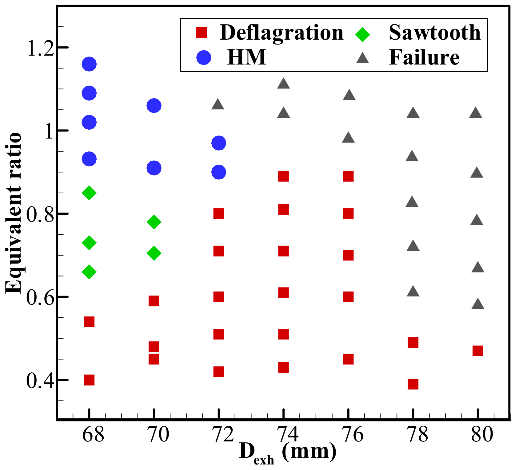
3.2. Operating Range and Combustion Modes

Figure 10 shows the distribution of the combustion mode under different operation conditions. All successful experiments were performed in the same time sequence (except for the long duration test) and the combustion can maintain stably in its mode within the preset experimental duration (3.33–3.94 s). Failure means that neither deflagration nor detonation can self-sustain in the experiment duration. The modes of deflagration, sawtooth wave, and HM are introduced in Section 3.1. When the Dexh was less than or equal to 72 mm, the combustion modes usually appeared in the sequence of deflagration, sawtooth wave, and HM, with ER increasing. Typically, the deflagration mode appeared at a relatively lower ER. For the deflagration cases, only a limited amount of ethylene was delivered to the combustor wall region, and it did not meet the minimum requirement for CRD formation. The lean combustible mixture was burnt at the rear of the combustor through deflagration. As ER increased, the enriched combustible mixture was effectively accumulated at the combustor wall region through the entrainment of the recirculation zone, which contributed to the formation of CRD in the combustor. The results in Figure 10 suggest that the sufficient combustible mixture accumulated in the outer wall region was crucial to the formation of CRD.
It is clear that the lean limits of the sawtooth wave and HM decreased with an increase in Dexh. The combustion mode shifted from the deflagration mode to the sawtooth wave when Dexh changed from 72 mm to 70 mm around ER = 0.7, and the mode shifted from deflagration mode to the HM when Dexh was reduced from 74 mm to 72 mm around ER = 0.9. The reduction in Dexh results in the combustor pressure increasing [28]. The increased combustor pressure contributes to a reduction in axial velocity and an increase in fuel residence time [29], which are essential for the proper accumulation of combustible mixture in the cavity forepart. The added circumferential contact surface between the cavity-stabilized flame in the re-circulation zone and the accumulation layer of the combustible mixture is a key factor of cavity enhancement [30]. In the higher axial velocity, the accumulation layer of the combustible mixture will be pushed downstream with relatively lower ER (The equivalent-mass fuel is distributed at a longer axial distance), and the impact of cavity enhancement will be weakened. The propellants cannot be completely reacted in the shortened distance. Note that the excessively low axial velocity is also adverse to accumulating the accumulation layer with the proper length. Besides, the lower axial velocity and longer residence time are conducive to the improvement of mixing quality and the completeness of reaction. Meanwhile, the increased combustor pressure is also advantageous to the chemical activity of CRD. In all, the HM and sawtooth wave could only be achieved in the Dexh range of 68–72 mm in this paper, and Dexh is a crucial factor for achieving CRD by reducing the axial velocity. As a result, the HM mode and sawtooth wave mode could not self-sustain when the ER remained stable and Dexh increased.
When the Dexh was equal to or larger than 74 mm, the only sustaining mode is deflagration mode. As the Dexh further increased, the deceleration impact of the incoming flow became less effective and the axial velocity increases distinctly, which resulted in poor mixing quality and short residence time. In the meantime, the re-circulation zone was compressed, and its ability for flame stabilization became weak [31]. Thus, the rich limit for deflagration decreased with the Dexh increasing, when Dexh was equal to or larger than 74 mm.

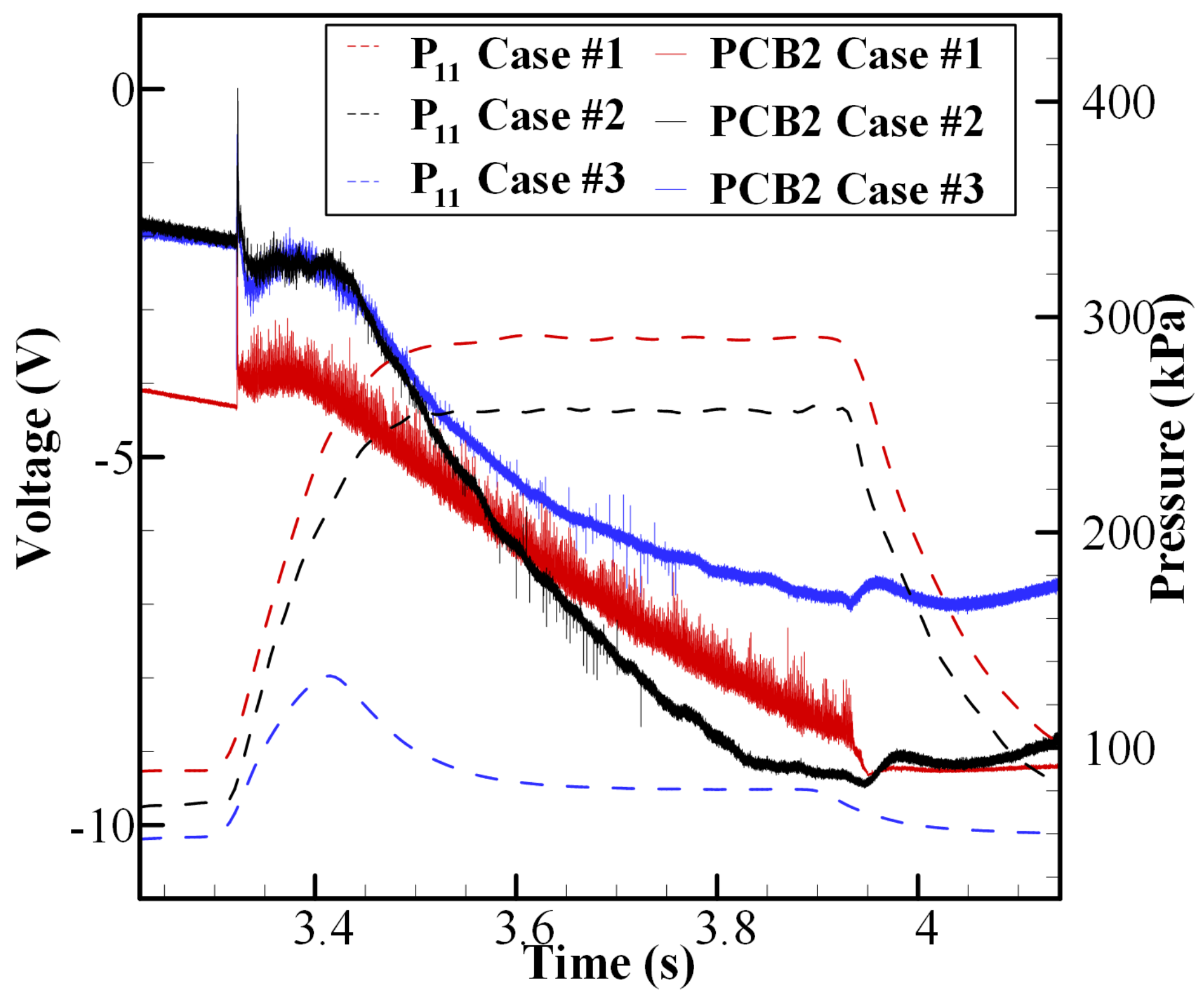
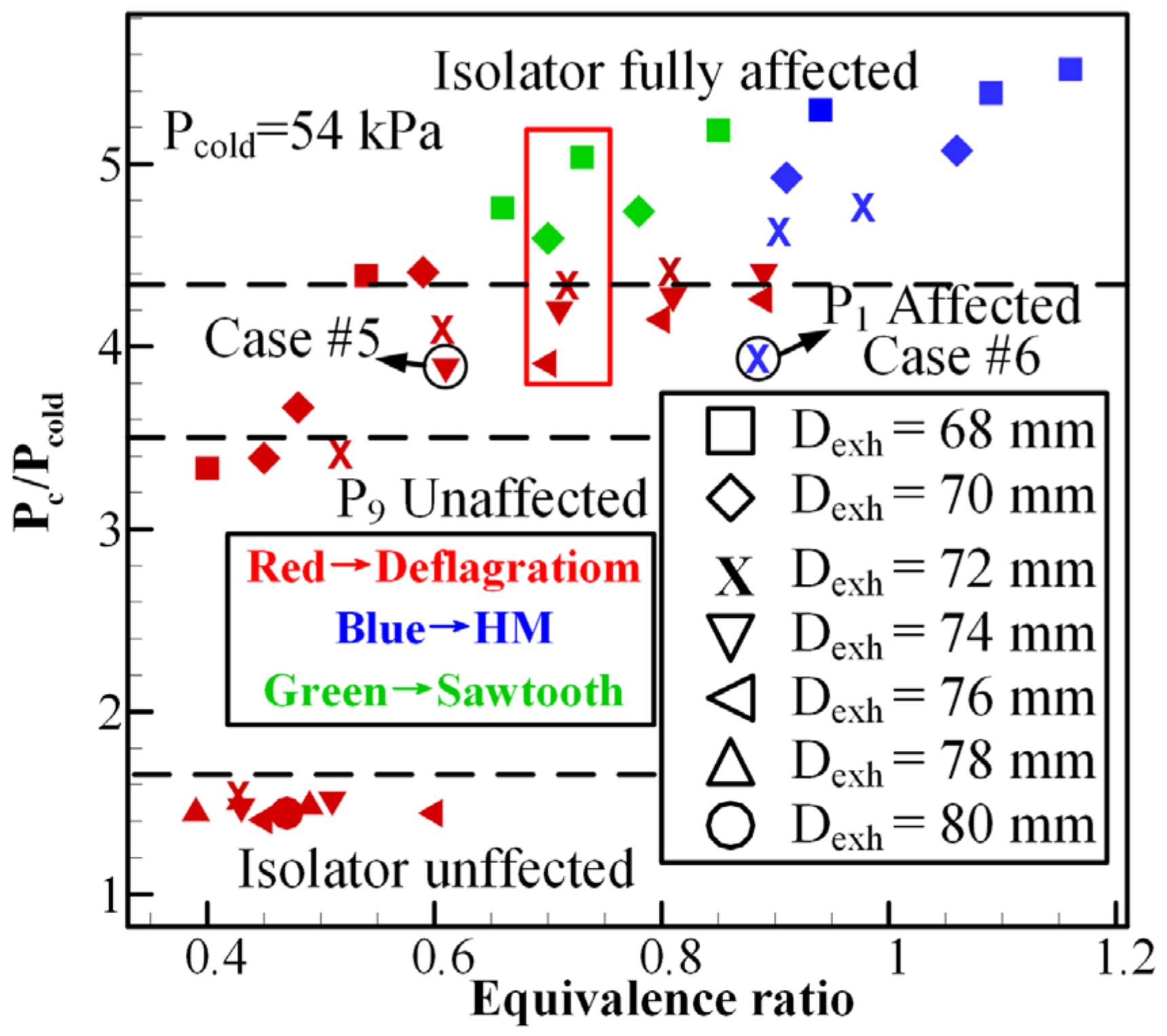
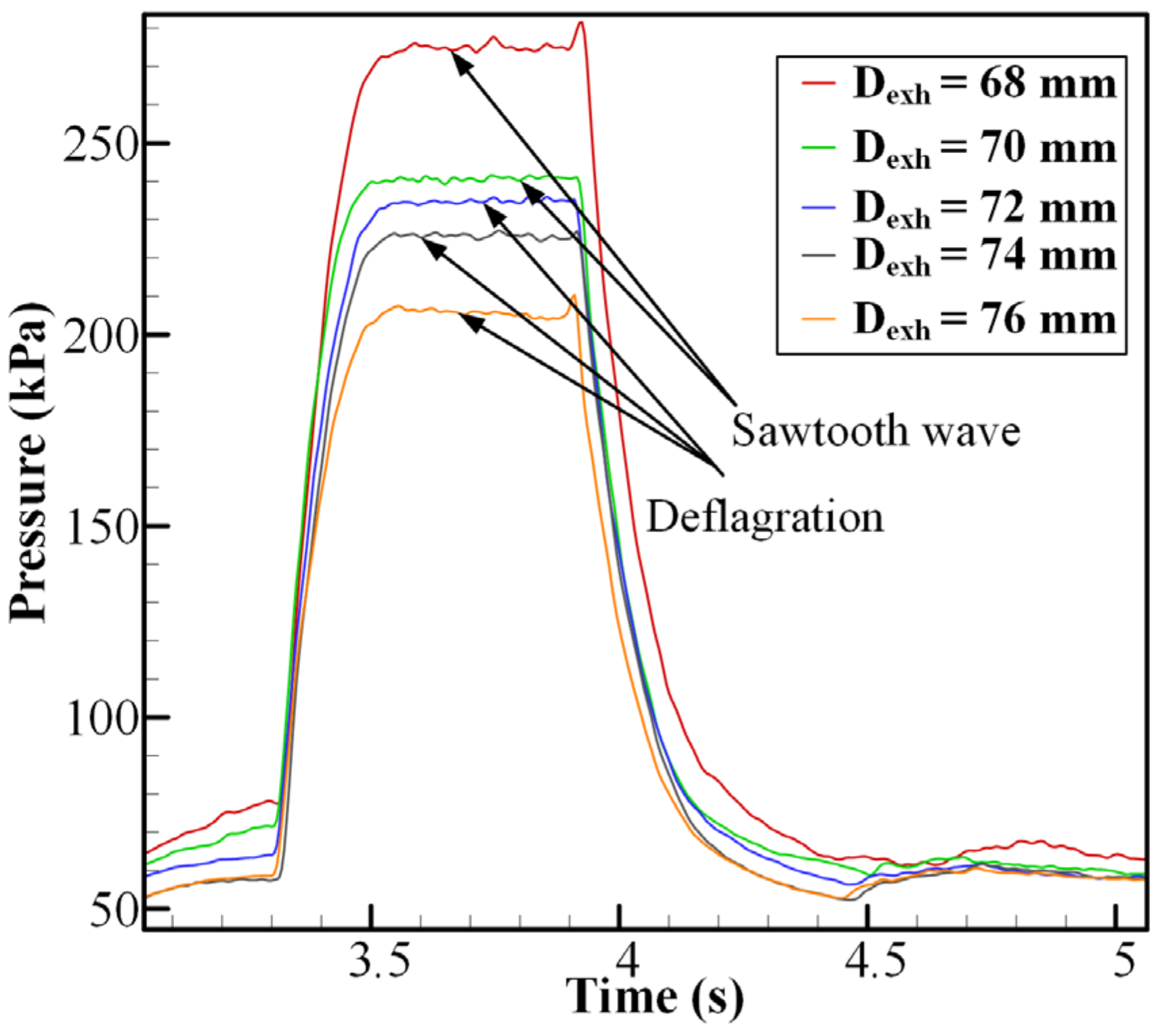
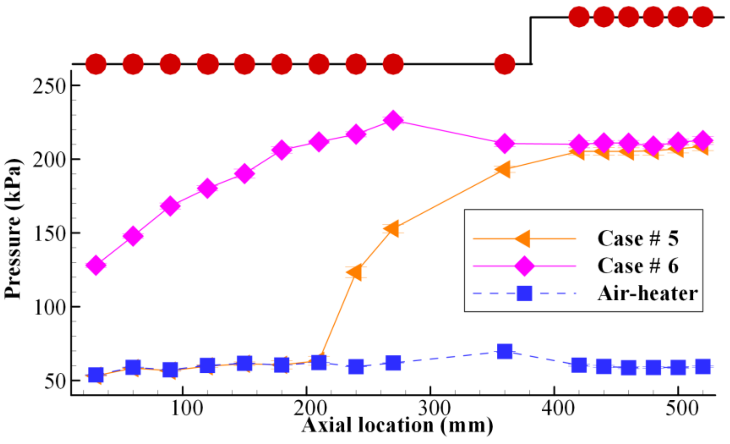
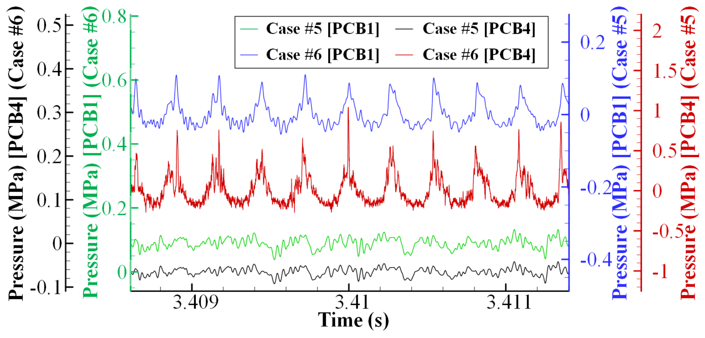
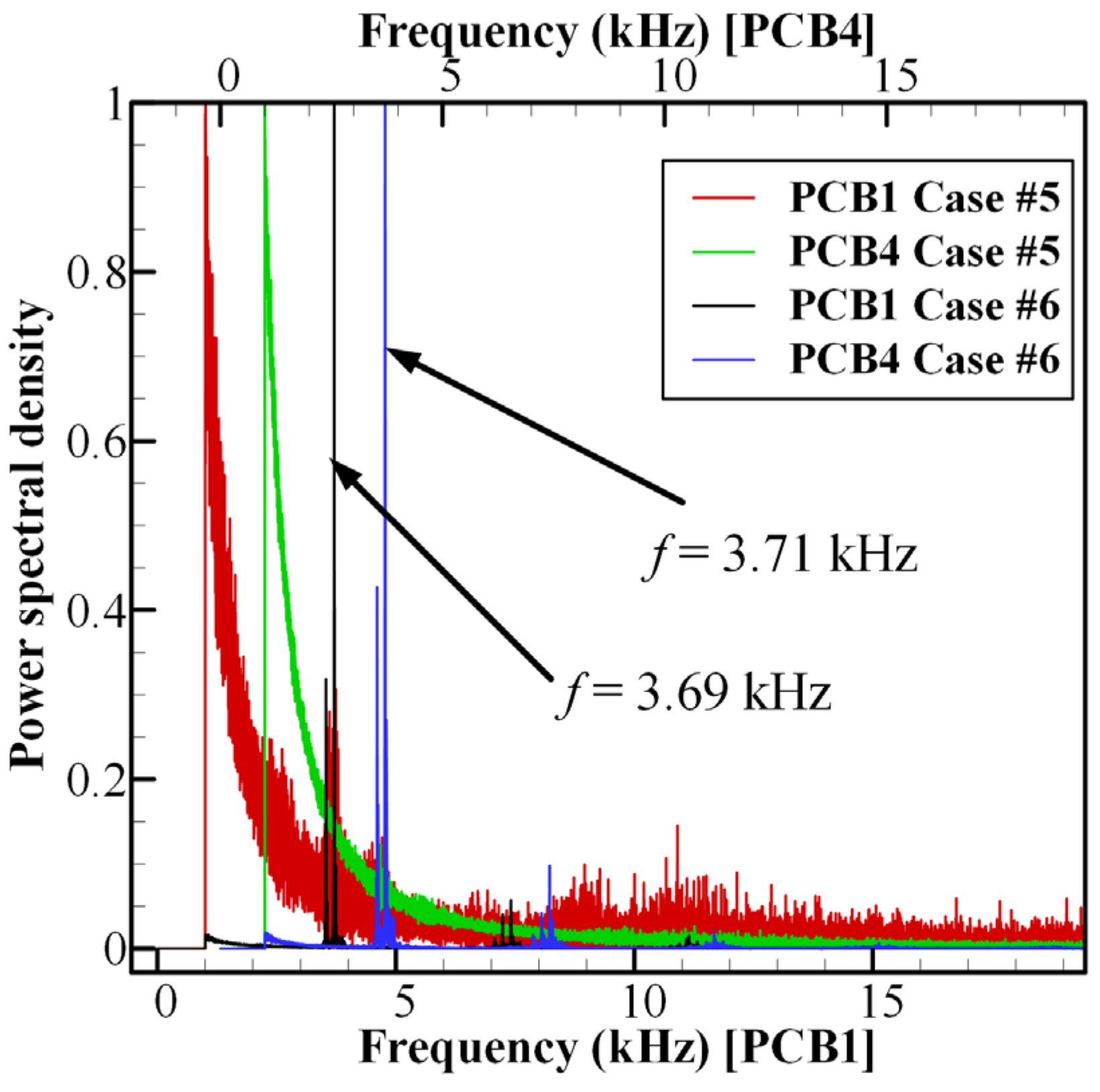
3.3. The Influence of Dynamic Backpressure on the Inflow

The results presented above demonstrate that combustion modes are sensitive to the exhaust nozzle. In this section, the impacts of Dexh on the combustor pressure and the air inflow are discussed. Figure 11 shows the pressure distributions along the streamwise direction with different ER values at Dexh = 68 mm. The wall pressure was collected and averaged during the stable combustion stage for each pressure transducer. The increase in combustor pressure in the sequence of “deflagration, sawtooth wave, and detonation” was mainly attributed to the mode transformation and partly to the increase in ER. The high back pressure of the combustor generally influenced the airflow with significantly different influence boundaries. The supersonic inflow remained unaffected before the ethylene injector for the deflagration case. The inflow was significantly impacted in the sawtooth wave and HM mode due to the higher combustor pressure. As a result, the preset supersonic inflow of Mach 2 was passively reduced to subsonic flow at the isolator entrance.
Figure 12 summarizes the combustor pressures for conditions of various Dexh and ER, in which the symbols and colors represent the Dexh and combustion modes, respectively. Pcold represents the wall pressure at the isolator inlet when the air-heater is operating stably. As illustrated in Figure 11, the pressure distribution in the combustor is essentially constant; thus, P11 can be used to represent the combustor pressure (Pc). The leading-edge location of the shock train is related to the ratio of Pc/Pcold, with a greater impact of a higher ratio on the inflow. The isolator was not affected when the Pc/Pcold was less than 2.61. When Pc/Pcold was in the range of 3.53 to 4.38, the leading edge of the shock train was located in the isolator. In these cases, all combustion modes were deflagration. In contrast, the incoming flow was completely affected when Pc/Pcold was larger than 4.38. This critical value is the upper limit for deflagration, but the sawtooth wave and HM can easily exceed this critical value. For Dexh = 68 mm, 70 mm, and 72 mm, Pc/Pcold eventually exceeded 3.53 and 4.38 with the increasing ER. This was mainly attributed to the combustion modes shifting from deflagration to detonation, resulting in a higher combustor pressure.
As shown in Figure 12, in the cases with similar ER and the smaller Dexh, the position of the leading edge of the shock train was located more upstream. The cases indicated with red boxes are typical cases used to show the relationship between the combustor pressure and Dexh, and where the cases have a similar ER. As shown in Figure 13, the combustor pressure increased as Dexh decreased. This is because the combustor pressure increases due to the increase in the blockage ratio of the nozzle throat [32]. Therefore, it can be concluded that the combustor pressure increases with the increasing ER and decreasing Dexh, and the shock train leading edge is located close to the isolator entrance due to the rising combustor pressure.
Prior analyses have demonstrated the effect of ER and Dexh on the incoming flow; however, the effect of combustion modes on incoming flow has not yet been analyzed. These two cases with similar combustor pressures, marked by a black circle in Figure 12, exhibit a distinct trend in their effects on air inflow. Figure 14 demonstrates the pressure distribution along the streamwise direction for these two cases. The different combustion modes (deflagration for Case #5, HM for Case #6) shared a similar combustor pressure, albeit with a minor difference. However, it was clear that the leading-edge location of the shock train in Case #6 was located more upstream than that in Case #5. The dynamic pressure distribution in the cylindrical isolator and combustor is shown in Figure 15. For Case #6, there was a periodic pressure oscillation detected in the combustor and isolator, and the pressure peaks in the isolator were much lower than those in the combustor. The periodic pressure oscillation detected in the isolator was supposedly caused by the oblique shock wave induced by the detonation wave, which is consistent with the numerical simulation results [33]. The frequency distribution of FFT shown in Figure 16 also proves the point mentioned above that the dominant frequency of PCB1 (3.69 kHz) is consistent with that of PCB4 (3.71 kHz), with a relative error of 0.5%. For Case #5, a clear periodic variation could not be clearly observed in the high-frequency pressures of the isolator and combustor. Figure 16 also clearly demonstrates that there was no dominant FFT frequency for Case #5. Thus, it can be concluded that the periodic high-frequency pressure oscillation could cause a more significantly substantial impact on the incoming flow than the steady deflagration, which is consistent with the conclusion reported in References [21,34].

4. Conclusions

A cylindrical isolator–combustor combination of the air-breathing continuous rotating detonation engine fueled by non-premixed ethylene/air with different exhaust nozzle diameters was investigated. A series of direct-connected tests were conducted at a temperature of 860 K and Mach number of 2. In this research, the impacts of nozzle throat diameter on combustion mode, operating range, and inflow have been discussed. Several main conclusions can be drawn as follows:
(1)
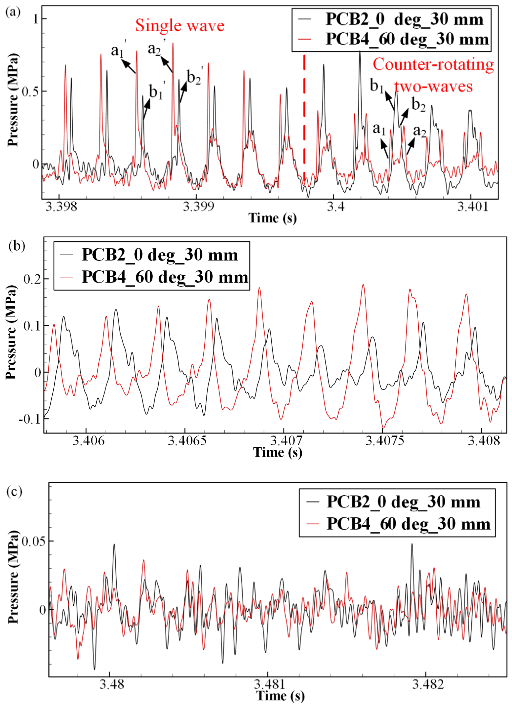
Three combustion modes were obtained under different operation conditions: deflagration, sawtooth wave, and hybrid mode. The counter-rotating two-waves and single wave alternated in the hybrid mode, which could be demonstrated in both high-frequency pressure measurements and high-speed imaging. In addition, the detonation combustion was observed to self-sustain in the combustor through the simultaneous high-speed imaging covering the combustor and isolator.
(2)
The detonation combustion is experimentally verified to maintain for more than three seconds in this unique engine configuration, indicating that the cylindrical isolator–combustor configuration exhibits potential for practical applications.
(3)
The nozzle throat diameter plays an essential role in whether the detonation wave can self-sustain. When the nozzle throat diameter was larger than the specific value, the increase in axial velocity and a reduction in fuel residence time would lead to an inappropriate accumulation of combustible mixture in the cavity forepart, resulting in neither detonation nor sawtooth wave self-sustaining. Meanwhile, the combustion modes were also sensitive to the nozzle throat diameter. The combustion mode could shift from deflagration to detonation/sawtooth wave with the same ER when the nozzle throat diameter was changed slightly.
(4)
The ER and nozzle throat diameter have a considerable influence on the leading edge location of the shock train. The leading edge location of the shockwave is supposed to be close to the isolator entrance in the condition of high ER and small nozzle throat diameter, which is mainly due to the detonation combustion and large blockage ratio of the nozzle. In addition, it has been verified that periodic high-frequency pressure oscillation could cause a significantly more substantial impact on the incoming flow than the steady deflagration with the close combustor pressure.
The cylindrical isolator–combustor combination of an air-breathing continuously rotating detonation engine was investigated under various exhaust nozzle configurations in this study. The effect of the nozzle throat diameter on the formation and self-sustaining of the detonation wave has been demonstrated. Further research should be conducted to gain a better understanding of how the rotating detonation wave affects the location of the shock train’s leading edge.

Author Contributions

Conceptualization, S.L. and G.W.; methodology, G.W.; validation, W.L.; formal analysis, G.W.; writing—original draft preparation, G.W.; writing—review and editing, G.W. and H.P.; supervision, W.L.; funding acquisition, W.L. All authors have read and agreed to the published version of the manuscript.

Funding

This study was supported by the National Natural Science Foundation of China through Grant No. (51776220).

Institutional Review Board Statement

Not applicable.

Informed Consent Statement

Not applicable.

Data Availability Statement

The data presented in this study is available on request from the corresponding author.

Conflicts of Interest

The authors declare no conflict of interest.

Abbreviations

Nomenclature
Ddiameter, mm
ffrequency, kHz
m ˙ mass flow rate, g/s
MaMach number
Ppressure
vvelocity, m/s
Subscripts
avaverage
C2H4ethylene plenum
cdetonation combustor
exhexhaust nozzle throat diameter
oxyoxygen
1–16pressure transducer number

Appendix A

Table A1. Operating conditions.
Test No. m ˙ A i r ,
g/s
ERCombustion ModeDexh,
mm
#1994 ± 200.41 ± 0.02Deflagration68
#2992 ± 200.54 ± 0.02Deflagration68
#3997 ± 200.66 ± 0.02Sawtooth wave68
#4998 ± 200.73 ± 0.02Sawtooth wave68
#51008 ± 200.85± 0.02Sawtooth wave68
#6988 ± 200.94 ± 0.02Hybrid mode68
#71006 ± 201.02 ± 0.02Hybrid mode68
#8994 ± 201.09 ± 0.02Hybrid mode68
#9998 ± 201.16 ± 0.02Hybrid mode68
#10998 ± 200.45 ± 0.02Deflagration70
#111007 ± 200.48 ± 0.02Deflagration70
#12996 ± 200.59 ± 0.02Deflagration70
#131012 ± 200.70 ± 0.02Sawtooth wave70
#141014 ± 200.78± 0.02Sawtooth wave70
#151007 ± 200.91 ± 0.02Hybrid mode70
#161010 ± 201.06 ± 0.02Hybrid mode70
#17999 ± 200.42 ± 0.02Deflagration72
#181005 ± 200.51 ± 0.02Deflagration72
#19998 ± 200.60 ± 0.02Deflagration72
#201002 ± 200.71 ± 0.02Deflagration72
#211003 ± 200.80 ± 0.02Deflagration72
#221001 ± 200.90 ± 0.02Hybrid mode72
#231005 ± 200.97 ± 0.02Hybrid mode72
#241001 ± 201.06 ± 0.02Failure72
#251005 ± 200.38 ± 0.02Deflagration74
#26998 ± 200.51 ± 0.02Deflagration74
#271002 ± 200.61 ± 0.02Deflagration74
#281003 ± 200.71 ± 0.02Deflagration74
#291001 ± 200.81 ± 0.02Deflagration74
#301005 ± 200.89 ± 0.02Deflagration74
#311001 ± 201.04 ± 0.02Deflagration74
#321003 ± 201.11 ± 0.02Failure74
#33995 ± 200.45 ± 0.02Deflagration76
#34996 ± 200.60 ± 0.02Deflagration76
#351005 ± 200.70 ± 0.02Deflagration76
#36989 ± 200.80 ± 0.02Deflagration76
#371002 ± 200.89 ± 0.02Deflagration76
#381003 ± 200.98 ± 0.02Failure76
#391005 ± 201.09 ± 0.02Failure76
#40994 ± 200.39 ± 0.02Deflagration78
#411005 ± 200.49 ± 0.02Deflagration78
#421001 ± 200.61 ± 0.02Failure78
#43995 ± 200.70 ± 0.02Failure78
#44992 ± 200.82 ± 0.02Failure78
#451003 ± 200.93 ± 0.02Failure78
#461001 ± 201.04 ± 0.02Failure78
#47999 ± 200.48 ± 0.02Deflagration80
#48994 ± 200.58 ± 0.02Failure80
#49996 ± 200.67 ± 0.02Failure80
#501004 ± 200.77 ± 0.02Failure80
#511007 ± 200.91 ± 0.02Failure80
#52995 ± 201.04 ± 0.02Failure80

References

  1. Kailasanath, K. Recent developments in the research on pulse detonation engines. AIAA J. 2003, 41, 145–159. [Google Scholar] [CrossRef]
  2. Braun, E.M.; Lu, F.K.; Wilson, D.R.; Camberos, J.A. Airbreathing rotating detonation wave engine cycle analysis. Aerosp. Sci. Technol. 2013, 27, 201–208. [Google Scholar] [CrossRef] [Green Version]
  3. Yan, C.; Teng, H.H.; Mi, X.C.; Ng, H.D. The effect of chemical reactivity on the formation of gaseous oblique detonation waves. Aerospace 2019, 6, 62. [Google Scholar] [CrossRef] [Green Version]
  4. Zhdan, S.A. Mathematical model of continuous detonation in an annular combustor with a supersonic flow velocity. Combust. Explos. Shock. Waves 2008, 44, 690–697. [Google Scholar] [CrossRef]
  5. Dubrovskii, A.V.; Ivanov, V.S.; Zangiev, A.E.; Frolov, S.M. Three-dimensional numerical simulation of the characteristics of a ramjet power plant with a continuous detonation combustor in supersonic flight. Russ. J. Phys. Chem. B 2016, 10, 469–482. [Google Scholar] [CrossRef]
  6. Smirnov, N.N.; Nikitin, V.F.; Stamov, L.I.; Mikhalchenko, E.V.; Tyurenkova, V.V. Rotating detonation in a ramjet engine three-dimensional modeling. Aerosp. Sci. Technol. 2018, 81, 213–224. [Google Scholar] [CrossRef]
  7. Smirnov, N.N.; Nikitin, V.F.; Stamov, L.I.; Mikhalchenko, E.V.; Tyurenkova, V.V. Three-dimensional modeling of rotating detonation in a ramjet engine. Acta Astronaut. 2019, 163, 168–176. [Google Scholar] [CrossRef]
  8. Wu, K.; Zhang, S.; Luan, M.; Wang, J. Effects of flow-field structures on the stability of rotating detonation ramjet engine. Acta Astronaut. 2020, 168, 174–181. [Google Scholar] [CrossRef]
  9. Wang, C.; Liu, W.; Liu, S.; Jiang, L.; Lin, Z. Experimental verification of air-breathing continuous rotating detonation fueled by hydrogen. Int. J. Hydrog. Energy 2015, 40, 9530–9538. [Google Scholar] [CrossRef]
  10. Wang, C.; Liu, W.; Liu, S.; Jiang, L.; Lin, Z. Experimental investigation on detonation combustion patterns of hydrogen/vitiated air within annular combustor. Exp. Therm. Fluid Sci. 2015, 66, 269–278. [Google Scholar] [CrossRef]
  11. Liu, S.; Liu, W.; Wang, Y.; Lin, Z. Free Jet Test of Continuous Rotating Detonation Ramjet Engine. In Proceedings of the 21st AIAA International Space Planes and Hypersonics Technologies Conference, Xiamen, China, 6–9 March 2017; p. 2282. [Google Scholar]
  12. Frolov, S.M.; Zvegintsev, V.I.; Ivanov, V.S.; Aksenov, V.S.; Shamshin, I.O.; Vnuchkov, D.A.; Nalivaichenko, D.G.; Berlin, A.A.; Fomin, V.M.; Shiplyuk, A.N.; et al. Hydrogen-fueled deto-nation ramjet model: Wind tunnel tests at approach air stream Mach number 5.7 and stagnation temperature 1500 K. Int. J. Hydrog. Energy 2018, 43, 7515–7524. [Google Scholar] [CrossRef]
  13. Meng, H.; Xiao, Q.; Feng, W.; Wu, M.; Han, X.; Wang, F.; Weng, C.; Zheng, Q. Air-breathing rotating detonation fueled by liquid kerosene in cavity-based annular combustor. Aerosp. Sci. Technol. 2022, 122, 107407. [Google Scholar] [CrossRef]
  14. Tang, X.; Wang, J.; Shao, Y.T. Three-dimensional numerical investigations of the rotating detonation engine with a hollow combustor. Combust. Flame 2004, 162, 997–1008. [Google Scholar] [CrossRef]
  15. Zhang, H.; Liu, W.; Liu, S. Effects of inner cylinder length on H2/air rotating detonation. Int. J. Hydrog. Energy 2016, 41, 13281–13293. [Google Scholar] [CrossRef]
  16. Peng, H.; Liu, W.; Liu, S.; Zhang, H.; Jiang, L. Hydrogen-air, ethylene-air, and methane-air continuous rotating detonation in the hollow chamber. Energy 2020, 211, 118598. [Google Scholar] [CrossRef]
  17. Yokoo, R.; Goto, K.; Kasahara, J.; Athmanathan, V.; Braun, J.; Paniagua, G.; Meyer, T.R.; Kawasaki, A.; Matsuoka, K.; Matsuo, A.; et al. Experimental study of internal flow structures in cylindrical rotating detonation engines. Proc. Combust. Inst. 2021, 38, 3759–3768. [Google Scholar] [CrossRef]
  18. Gejji, R.M.; Buschhagen, T.; Slabaugh, C.D. Occurrence of Rotating Detonation Waves in a Jet-Stabilized Combustor with Premixed Injection. J. Propuls. Power 2021, 37, 645–649. [Google Scholar] [CrossRef]
  19. Wang, G.; Liu, W.; Liu, S.; Zhang, H.; Peng, H.; Zhou, Y. Experimental verification of cylindrical air-breathing continuous rotating detonation engine fueled by non-premixed ethylene. Acta Astronaut. 2021, 189, 722–732. [Google Scholar] [CrossRef]
  20. Huang, W.; Wang, Z.; Pourkashanian, M.; Ma, L.; Ingham, D.B.; Luo, S.; Lei, J.; Liu, J. Numerical investigation on the shock wave transition in a three-dimensional scramjet isolator. Acta Astronaut. 2011, 68, 1669–1675. [Google Scholar] [CrossRef]
  21. Su, W.; Ji, Y.; Chen, Y. Effects of dynamic backpressure on pseudoshock oscillations in scramjet inlet-isolator. J. Propuls. Power 2016, 32, 516–528. [Google Scholar] [CrossRef]
  22. Rankin, B.A.; Fugger, C.A.; Richardson, D.R.; Cho, K.Y.; Hoke, J.; Caswell, A.W.; Gord, J.R.; Schauer, F. Evaluation of Mixing Processes in a Non-Premixed Rotating Detonation Engine Using Acetone PLIF. In Proceedings of the 54th AIAA Aerospace Sciences Meeting, San Diego, CA, USA, 4–8 January 2016; p. 1198. [Google Scholar]
  23. Sun, M.; Gong, C.; Zhang, S.; Liang, J.; Liu, W.; Wang, Z. Spark ignition process in a scramjet combustor fueled by hydrogen and equipped with multi-cavities at Mach 4 flight condition. Exp. Therm. Fluid Sci. 2012, 43, 90–96. [Google Scholar] [CrossRef]
  24. Peng, H.; Liu, W.; Liu, S.; Zhang, H. Experimental investigations on ethylene-air Continuous Rotating Detonation wave in the hollow chamber with Laval nozzle. Acta Astronaut. 2018, 151, 137–145. [Google Scholar] [CrossRef]
  25. Betelin, V.B.; Nikitin, V.F.; Mikhalchenko, E.V. 3D numerical modeling of a cylindrical RDE with an inner body extending out of the nozzle. Acta Astronaut. 2020, 176, 628–646. [Google Scholar] [CrossRef]
  26. Wu, Y.; Weng, C.; Zheng, Q.; Wei, W.; Bai, Q. Experimental research on the performance of a rotating detonation combustor with a turbine guide vane. Energy 2021, 218, 119580. [Google Scholar] [CrossRef]
  27. Yang, C.; Wu, X.; Ma, H.; Peng, L.; Gao, J. Experimental research on initiation characteristics of a rotating detonation engine. Exp. Therm. Fluid Sci. 2016, 71, 154–163. [Google Scholar] [CrossRef]
  28. Wang, Y.; Le, J.; Wang, C.; Zheng, Y.; Huang, S. The effect of the throat width of plug nozzles on the combustion mode in rotating detonation engines. Shock. Waves 2019, 29, 471–485. [Google Scholar] [CrossRef]
  29. Sun, J.; Zhou, J.; Liu, S.; Lin, Z.; Lin, W. Numerical investigation of a non-premixed hollow rotating detonation engine. Int. J. Hydrog. Energy 2019, 44, 17084–17094. [Google Scholar] [CrossRef]
  30. Peng, H.Y.; Liu, S.J.; Liu, W.D.; Yuan, X.Q.; Cai, X.D. Enhancement of ethylene-air continuous rotating detonation in the cavity-based annular combustor. Aerosp. Sci. Technol. 2021, 115, 106842. [Google Scholar] [CrossRef]
  31. Yang, Y.; Wang, Z.; Zhang, Y.; Sun, M.; Wang, H. Flame stabilization with a rear-wall-expansion cavity in a supersonic combustor. Acta Astronaut. 2018, 152, 752–756. [Google Scholar] [CrossRef]
  32. Manda, L.J. Spin effects on rocket nozzle performance. J. Spacecr. Rocket. 1966, 3, 1695–1696. [Google Scholar] [CrossRef]
  33. Wu, K.; Zhang, S.J.; She, D.W.; Wang, J.P. Analysis of flow-field characteristics and pressure gain in air-breathing rotating detonation combustor. Phys. Fluids 2022, 33, 126112. [Google Scholar] [CrossRef]
  34. Cai, J.; Zhou, J.; Liu, S.; Lin, Z. Effects of dynamic backpressure on shock train motions in straight isolator. Acta Astronaut. 2017, 141, 237–247. [Google Scholar] [CrossRef]
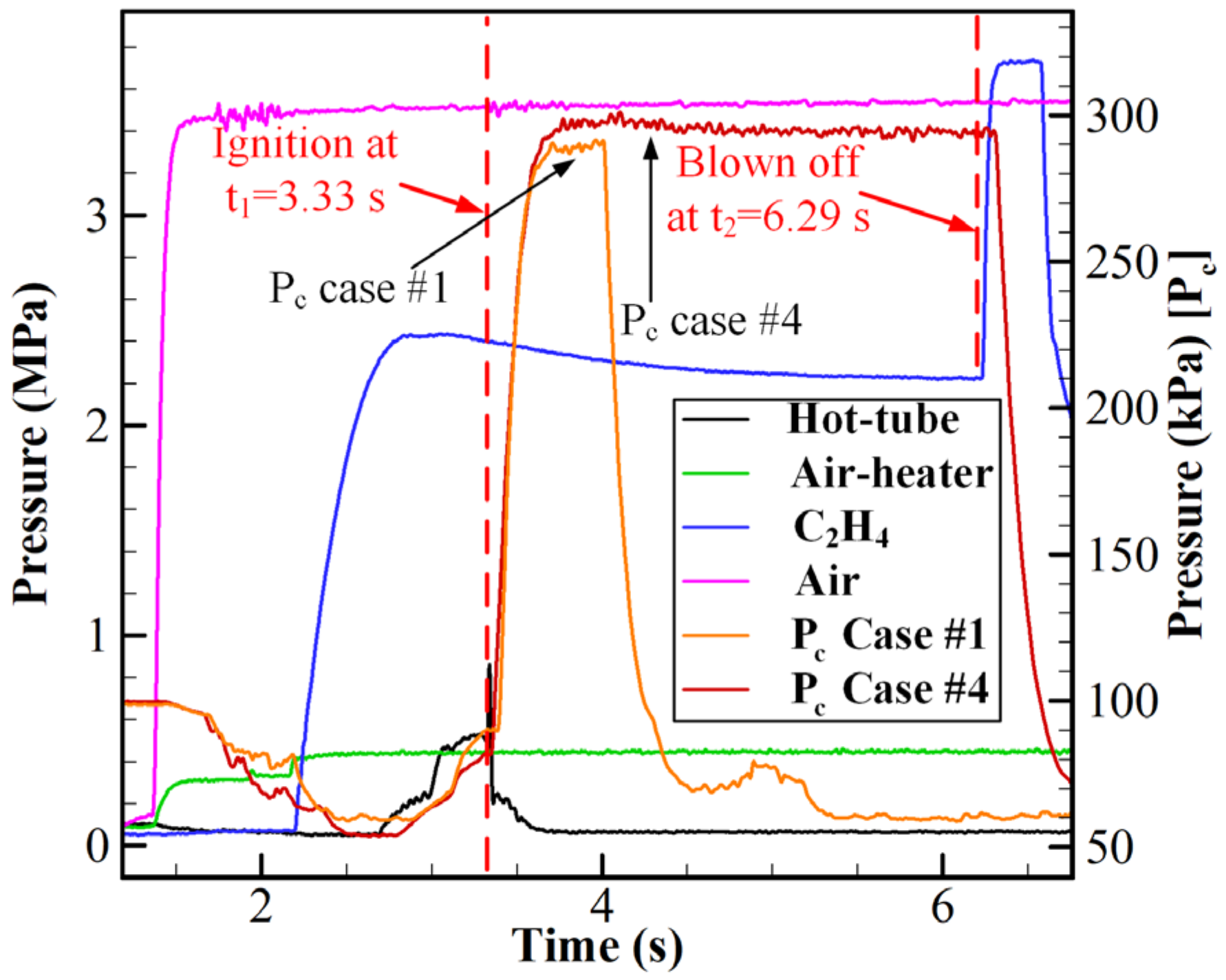
Figure 1. Schematic view of the cylindrical isolator and combustor engine: (a) Maxwell pressure transducers installation locations; (b) PCB sensor installation locations.
Aerospace 09 00267 g001
Figure 2. Photograph of the cylindrical air-breathing CRD engine.
Aerospace 09 00267 g002
Figure 3. Time sequence of the CRD experiments.
Aerospace 09 00267 g003
Figure 4. The original voltage signals and the static wall pressure.
Aerospace 09 00267 g004
Figure 5. Local view of dynamic high-frequency pressure for three different combustion modes: (a) hybrid mode (Case #1); (b) sawtooth wave mode (Case #2); and (c) deflagration mode (Case #3).
Aerospace 09 00267 g005
Figure 6. High-speed images of the ignition process of Case #1. (Original images).
Aerospace 09 00267 g006
Figure 7. Local view of dynamic high-frequency pressure of Case #1.
Aerospace 09 00267 g007
Figure 8. High-speed images of Case #1: (a) single wave; (b) two-wave counter-rotating.
Aerospace 09 00267 g008
Figure 9. Air-heater and combustor pressure with time (Case #4).
Aerospace 09 00267 g009
Figure 10. Operating range of combustion modes under the various diameter of the exhaust nozzle.
Aerospace 09 00267 g010
Figure 11. Pressure distribution in the streamwise direction for Dexh = 68 mm and Dc = 112 mm with different ER values.
Aerospace 09 00267 g011
Figure 12. Combustor pressure distributions under different operating conditions.
Aerospace 09 00267 g012
Figure 13. Combustor wall pressure distribution with different Dexh and similar ER values.
Aerospace 09 00267 g013
Figure 14. Pressure distribution along the streamwise direction.
Aerospace 09 00267 g014
Figure 15. Local view of dynamic high-frequency distribution for Cases #5 and #6.
Aerospace 09 00267 g015
Figure 16. FFT distribution of Case #5 and #6 in the isolator and combustor.
Aerospace 09 00267 g016
Table 1. Typical experiments with different combustion modes.
Case No. m ˙ A i r ,
g/s
ERCombustion ModeDexh,
mm
f, kHzNote
#1994 ± 201.09 ± 0.02Hybrid mode683.73×
#2995 ± 200.78 ± 0.02Sawtooth wave703.82×
#3997 ± 200.38 ± 0.02Deflagration74××
#4998 ± 201.16 ± 0.02Hybrid mode68×Long CRD test
Publisher’s Note: MDPI stays neutral with regard to jurisdictional claims in published maps and institutional affiliations.

