Article

Additive Manufacturing of Novel Hybrid Monolithic Ceramic Substrates

1
Department of Mechanical Engineering, University of Birmingham, Birmingham B15 2TT, UK
2
School of Electromechanical Engineering, Guangdong University of Technology, Guangzhou 510006, China
*
Authors to whom correspondence should be addressed.
Aerospace 2022, 9(5), 255; https://doi.org/10.3390/aerospace9050255
Submission received: 30 March 2022 / Revised: 29 April 2022 / Accepted: 5 May 2022 / Published: 7 May 2022
(This article belongs to the Special Issue Additive Manufacturing of Ceramic Materials in Aerospace)

Abstract

:
Additive manufacturing (AM) can revolutionise engineering by taking advantage of unconstrained design and overcoming the limitations of traditional manufacturing capabilities. A promising application of AM is in catalyst substrate manufacturing, aimed at the enhancement of the catalytic efficiency and reduction in the volume and weight of the catalytic reactors in the exhaust gas aftertreatment systems. This work addresses the design and fabrication of innovative, hybrid monolithic ceramic substrates using AM technology based on Digital Light Processing (DLP). The designs are based on two individual substrates integrated into a single, dual-substrate monolith by various interlocking systems. These novel dual-substrate monoliths lay the foundation for the potential reduction in the complexity and expense of the aftertreatment system. Several examples of interlocking systems for dual substrates were designed, manufactured and thermally post-processed to illustrate the viability and versatility of the DLP manufacturing process. Based on the findings, the sintered parts displayed anisotropic sintering shrinkage of approximately 14% in the X–Y direction and 19% in the Z direction, with a sintered density of 97.88 ± 0.01%. Finally, mechanical tests revealed the mechanical integrity of the designed interlocks. U-lock and Thread configurations were found to sustain more load until complete failure.

1. Introduction

Ceramic monolithic substrates find substantial commercial use in the automotive industry as catalyst supports for the purification of noxious exhaust gases in aftertreatment systems [1]. Despite the high surface area and low backpressure of the conventional honeycomb substrates, manufacturing constraints preclude any further improvements in their design for enhancing the catalytic activity. Therefore, compliance with present and forthcoming rigorous vehicle emission legislation poses major difficulties.
It is of interest to reduce the number of individual catalytic systems (e.g., by merging their functions) in the exhaust aftertreatment to reduce the system’s volume and weight. For instance, a typical diesel exhaust aftertreatment system can incorporate four separate catalytic systems: catalysed diesel particulate filter (DPF), a catalyst for selective catalytic reduction of nitrogen oxides (NOx) with ammonia (NH3-SCR), an ammonia slip catalyst (ASC) and a diesel oxidation catalyst (DOC) [2]. Solutions to simplify the state-of-the-art aftertreatment arrangement to decrease the volume and weight of the aftertreatment system, have been suggested in the past. For example, an all-in-one four-way catalytic converter (FWCC) combines oxidation–reduction catalysts to simultaneously remove carbon monoxide, hydrocarbons, particulate matter, and nitrogen oxides. The FWCC is an efficient solution to the limited space capacity in the aftertreatment. However, the complex multi-phase reaction processes where the species interact with each other and compete for active sites affect the catalytic efficiency. On the other hand, dual-catalyst configurations can improve the efficiency of a single component, such as the one proposed by Lefort et al. [3], by placing a DOC catalyst with lower thermal mass to quickly light-off in front, and a DOC catalyst with higher thermal mass in the back to store heat. Moreover, layering of active washcoats on top of one another, or zoning, where the active component concentration in the washcoat changes along the axial length, can have a considerable influence on the catalytic light-off of single components in the aftertreatment. Hazlett et al. [4] showed that Pt-Pd catalysts can be zoned axially along the monolith in varying ratios to increase NO oxidation selectivity by promoting CO oxidation with a larger quantity of Pd at the front, and higher amounts of Pt along the length for NO oxidation. Furthermore, taking advantage of the particular operating temperature range of the individual active materials in SCR can be achieved by layering and zoning Fe/ZSM-5 and Cu/zeolite [4]. The aforementioned layouts do not offer any space savings, but they do have the ability to minimise the precious metal loading and the overall cost.
Innovative aftertreatment solutions aimed at the improvement of the performance of the aftertreatment systems, such as exhaust gas fuel reforming, to provide a small concentration of hydrogen (H2) to the aftertreatment catalyst show great potential [5,6,7]. Direct hydrogen addition positively affects the performance of various aftertreatment devices, including catalytic converters, DPF and NOx traps [6,8,9]. However, the addition of an on-board catalytic reformer to produce H2-enriched exhaust gas adds complexity, weight, and volume to the already complex aftertreatment system.
Moreover, in the aerospace sector, additively manufactured monolithic catalysts with high surface areas and low-pressure drops can be employed as monopropellant thrusters. As a result of increased interest in hydrazine-based propellant alternatives, catalysts for high test peroxide (HTP), hydroxylammonium nitrate (HAN) or ammonium dinitramide (ADN) propellant blends have received considerable attention in the last two decades. Within the project Rheform, additively manufactured monolith catalysts with straight channels, cellular structure and polyhedral structure were presented to improve the ADN-based propulsion systems [10]. Moreover, Koopmans et al. [11] compared the performance of the complex additively manufactured monoliths with extruded catalysts with respect to the decomposition of highly concentrated hydrogen peroxide. Decomposition tests revealed that the AM catalysts showed an increase in the temperature transient time compared to the extruded one. Metallic gauzes or screens, ceramic pellets coated with an active catalytic phase or extruded monolithic beds are currently employed in HTP catalyst applications. However, fragmentation, high pressure drop and flooding are common issues in these configurations [12]. Essa et al. [12] have demonstrated additively manufactured high-performance monolithic catalyst beds with complicated geometries for use in hydrogen peroxide monopropellant thruster. The AM catalysts outperformed MnOx-coated ceria pellets while providing an acceptable pressure drop.
Ceramic additive manufacturing has lately undergone substantial research, introducing brand new possibilities in the design and fabrication of novel monolithic substrates for various applications [13,14,15,16,17]. In recent years, significant scientific efforts have been focused on enhancing the efficiency of the catalyst substrates. Alteration of the substrate design by introducing lattice-based substrates was found to offer advantages in terms of chemical activity over the conventional channel design [18,19]. In light of the opportunities provided by additive manufacturing processes, AM techniques such as robocasting [20], liquid deposition modelling [21], laser-based stereolithography (SLA) [19] and digital light processing (DLP) [18] have been successfully utilised to manufacture ceramic catalytic substrates with intricate lattice structures. DLP is one of the additive manufacturing technologies suitable for the fabrication of complex ceramic monolithic substrates with fine features [22]. To create an image, DLP projectors use a digital micromirror device chip (DMD) and a light source, where each image layer is projected onto a layer of photosensitive ceramic slurry, which hardens when exposed to the light source, and the process is repeated until the green body is formed [23]. Upon finalising the green body shaping, the part is removed from the building platform, cleaned from any residual slurry and subjected to debinding and sintering process to obtain the final dense part. Removal of the photopolymerised resin from the interspace of the ceramic particles, known as debinding, is a critical step in the post-treatment. Slow heating rates and appropriate holding temperatures are necessary to avoid delamination, cracks, deformation or collapse caused by thermal stress from the decomposition of the organic components [24]. During the sintering stage at high temperatures, a dense ceramic part is achieved.
In this work, a proof-of-concept is presented to propose a potential solution for the aftertreatment reactor complexity reduction. A procedure to design, additively manufacture and thermally post-process dual-substrate emission control hybrid supports, that could be separately coated with active material and integrated into a single brick, is proposed. This concept can be applied in catalytic applications where space savings are beneficial. Several interlocking mechanisms are presented to demonstrate the DLP manufacturing process’s feasibility and flexibility.

2. Materials and Methods

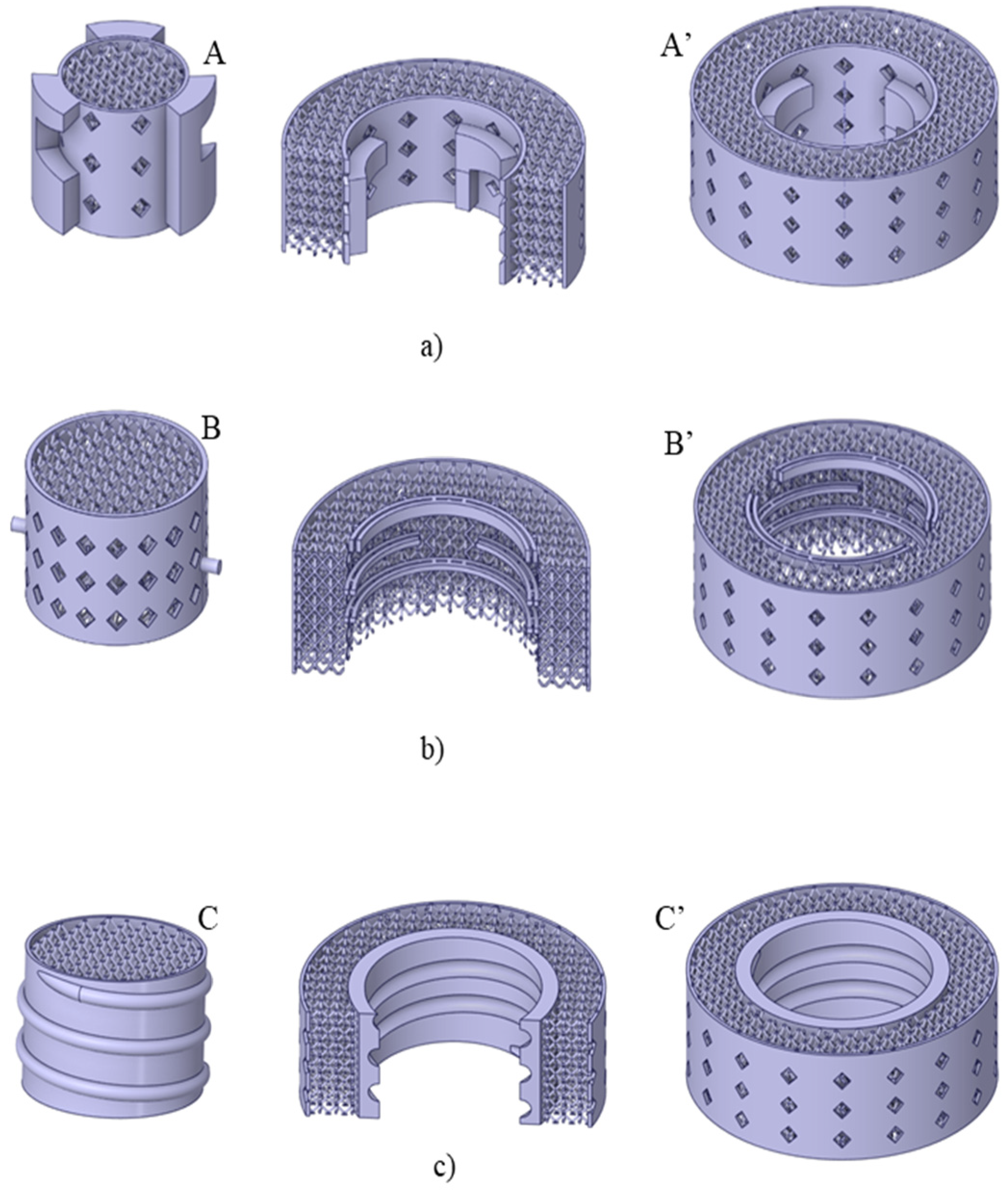
2.1. Interlock Designs

The three-dimensional models were designed using CATIA and Ansys SpaceClaim 2020R1 CAD software. The structure of the substrates is based on a unit cell of a diamond lattice [12,18]. The substrates feature a cylindrical core with an interlocking mechanism on the outer surface and a shell substrate with an interlocking mechanism in the cored centre. The CAD designs of the interlocking mechanisms are shown in Figure 1.
The U-lock design shown in Figure 1a features horizontal U-shaped protrusions on the surface of the core part (A). After aligning the core and the shell (A’) the core is lowered into the cylindrical protrusion of the shell substrate and rotated counterclockwise to allow the U-shaped protrusions to slide over the horizontal arms of the inverted capital letter L-shaped protrusions in the shell substrate.
The core (B) in the Twist-lock design, shown in Figure 1b, has two radial pins that align with the slots of the helical protrusions in the shell substrate (B’). The core is twisted clockwise until it reaches the next slots, lowered into the second row of the helical protrusion, where the core is then twisted counterclockwise until it locks into place.
The fastening mechanism of the Thread in Figure 1c consists of a core part (D) that has an external male thread (helical ridges that spiral around the part) while the shell (D’) has an internal thread that allows the coupling of the two.

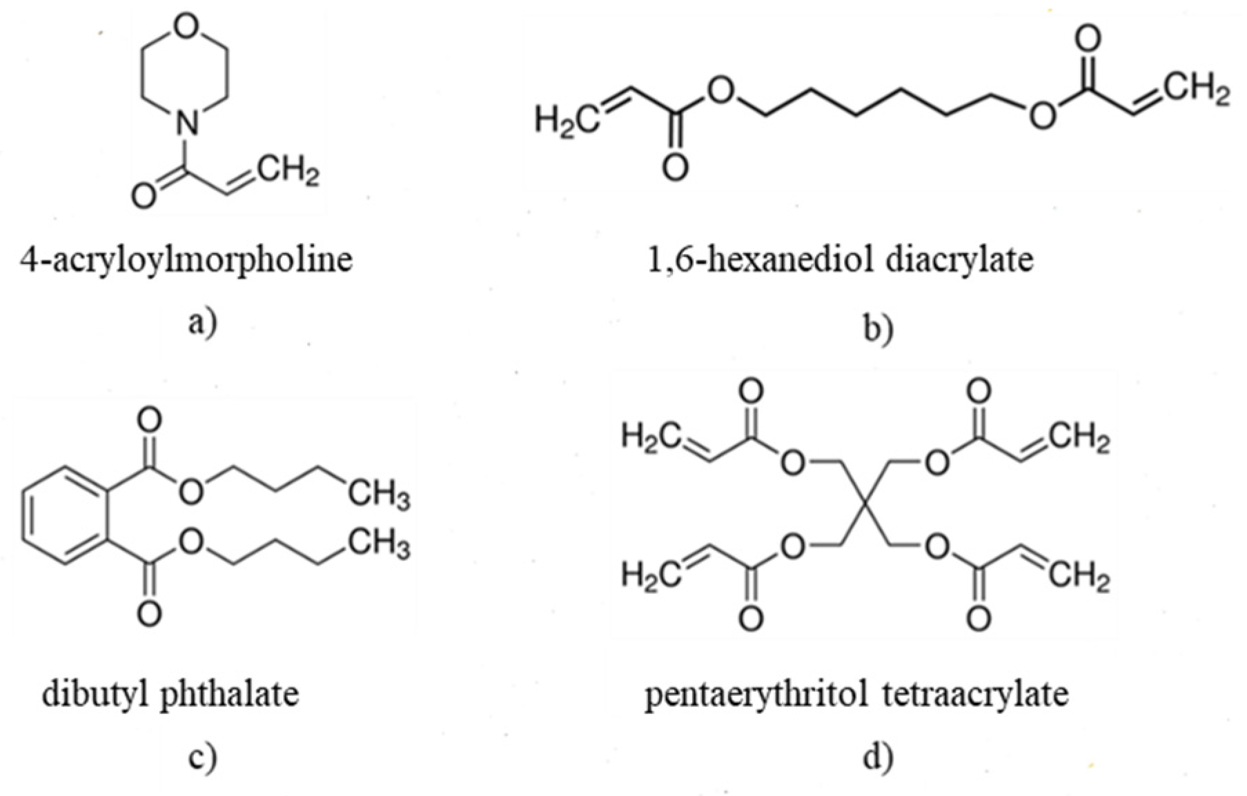
2.2. Ceramic Slurry Preparation and Characterisation

The ceramic slurry was prepared in-house by first combining the components of the resin: 33.4 wt% of 4-acryloylmorpholine (TCI, Tokyo, Japan), 28 wt% of 1,6-hexanediol diacrylate (TCI, Tokyo, Japan), 18.6 wt% of pentaerythritol tetraacrylate (TCI, Tokyo, Japan) and 20 wt% of dibutyl phthalate (Sigma Aldrich, Gillingham, UK) The chemical structure of the materials used for the preparation of the resin is shown in Figure 2.
The resin components were mixed with an overhead mixer at room temperature for 30 min. Commercially available alumina oxide powder (A16 SG, Almatis GmbH, Ludwigshafen, Germany) was pre-treated with 2 wt% of Disperbyk-145 (BYK Chemie, Wesel, Germany) dispersant according to the procedure described in [22]. Following the pre-treatment, the dispersant pre-treated ceramic powder was incorporated into the resin mixture to achieve 57 vol% solid loading. In the final step, 0.1 wt% (to the reactive resin) of diphenyl (2,4,6-trimethylbenzoyl) phosphine oxide (Sigma Aldrich, Gillingham, UK) was added to initiate the polymerisation reactions and the slurry was thoroughly mixed overnight on a turbula mixer. Before the use on the printer, the slurry was placed under vacuum to remove any air bubbles. The particle size distribution of the pre-treated ceramic powder was evaluated with Sympatec Helos (Sympatec GmbH, Clausthal-Zellerfeld, Germany) using R1 lens. The rheology of the prepared slurry was tested on AR 500 (TA Instruments, New Castle, DE, USA) with a 20 mm parallel plate geometry varying the shear rate from 0.1 to 300 s−1 at a constant temperature of 20.0 °C.

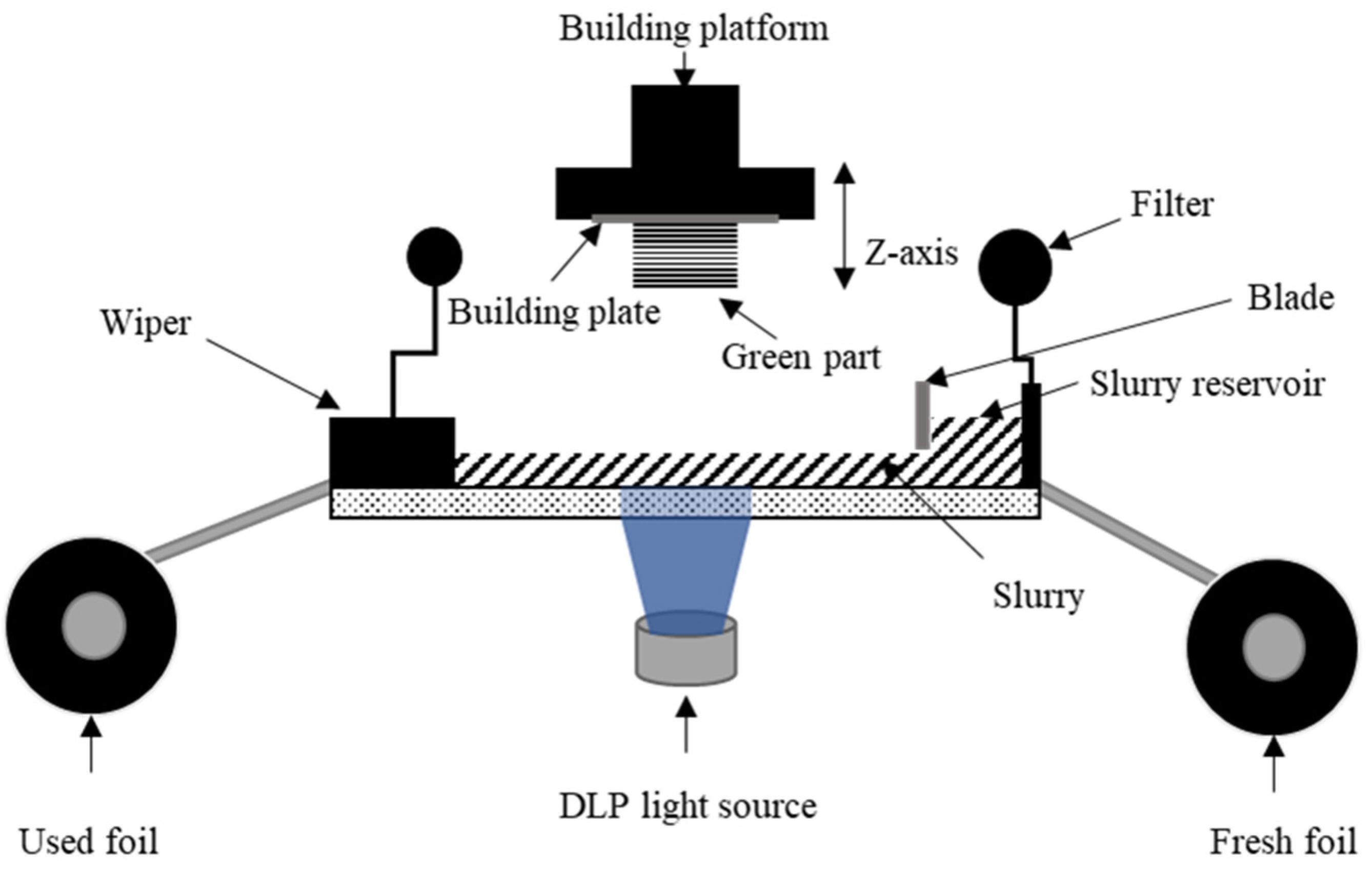
2.3. Green Body Shaping via DLP

The parts were printed using an Admaflex 130 printer, a DLP-based additive manufacturing system developed and commercialised by Admatec Europe (Admatec Europe BV, Nobelstraat, The Netherlands). The prepared. STL files were sliced to a layer thickness of 25 µm using the machine’s slicing software. The key parameters of the machine are summarised in Table 1.
The main components of the machine (Figure 3) are (i) the building platform with a build plate, (ii) glass bottom, (iii) light projector, (iv) slurry reservoir, (v) wiper and (vi) foil rolls. In the first step of the printing process, the slurry is transported on the foil from the reservoir to the building area by the rotating foil system. The building platform then descends until the distance between the platform and the slurry layer is equal to one-layer thickness. The light projects the slice information to the slurry layer and the illuminated suspension is cured for several seconds. The building platform ascends, the excess slurry is transported to the wiper and pumped back into the reservoir. A new slurry layer is recoated, and the platform descends to a distance equal to a one-layer thickness between the first cured layer and the slurry layer. The next layer is then cured and adhered to the previous layer. The process of slurry transport and layer-by-layer curing is repeated until the product is built.
Given the rigid nature of the cured slurry, direct printing of the part on the base layers resulted in a difficult part extraction. Hence, sacrificial layers were added to the starting CAD models. Furthermore, to ease the detachment of the sacrificial layers from the base, 8 base layers were cured with a light intensity of 27.3 mW/cm2 and an exposure time of 4 s. The intermediate layers were printed by decreasing the light intensity from 27.3 to 14 mW/cm2 in increments of 3.3–3.4 mW/cm2 at an exposure time of 4 s, followed by decreasing the exposure time at a constant light intensity of 14 mW/cm2, layer-by-layer, until 3 s were reached. The rest of the layers were exposed with an intensity of 14 mW/cm2 and an exposure time of 3 s. After the parts were built, they were extracted from the platform and the sacrificial layers were cut from the green parts. The green parts were then cleaned from the non-polymerised slurry with the dibasic ester (Sigma Aldrich, Gillingham, UK) and dried in atmospheric conditions and thermally post-processed via debinding and sintering.

2.4. Thermal Post-Processing of the Green Bodies

The debinding program was derived from the Thermogravimetric Analysis (TGA) and Differential Scanning Calorimetry (DSC) of the cured slurry that was carried out on a simultaneous analyser SDT NETZSCH STA in dynamic air (100 mL/min) with a heating rate of 5 °C/min. The debinding process was carried out in a tube furnace (TSH/1S/75/450, Elite Thermal Systems Ltd., Market Harborough, UK). After debinding, the specimens were sintered in a chamber furnace (HTF 17/27, Carbolite Gero, Sheffield, UK) at 1540 °C with a dwell time of 2 h and a heating and cooling rate of 3 °C/min in an air atmosphere. Both thermal processes were carried out under the air atmosphere. The linear shrinkage of the samples was obtained by using measurements of sample dimension in X–Y and Z directions, achieved by using a Vernier caliper, before and after sintering and calculated by the following equation:
L i = G i S i G i × 100   %
where L i is the linear shrinkage, G i is the dimension of the sample before sintering (green stage) and S i is the dimension of the sample after sintering. The index i represents X–Y or Z direction.

2.5. Part Characterisation

Structural integrities of the interlocking mechanisms were tested under compression at 0.5 mm/min (Instron 4467 series model, High Wycombe, UK) with a rod fixture of 12.7 mm diameter. Displacements and loads were recorded with a 30 kN load cell. A bespoke sample holder with a cylindrical groove was designed to hold the testing specimen and to form a space for the fractured material to fall into. The sample holder was held in place by neodymium disc magnets. Sintered density was estimated using Archimedes’ principle with distilled water as the emersion medium and given as a percent of the relative density. The equipment used to measure the density of the samples was an Ohaus Adventurer Analytical Balance, with the Archimedes’ principle measurement complement. This analytical balance allows the direct measurement of the density with a program routine that realises the intermediate calculation. The theoretical density of the Al2O3 was taken from the manufacturer’s specifications (3.95 g/cm3). Vernier caliper was used to characterise the dimensions of the parts before and after sintering. The microstructure of the green and sintered bodies was studied using scanning electron microscopy (SEM) (TM3030 Tabletop SEM, Hitachi High-Technologies, Tokyo, Japan). The fracture surface was examined using SEM (JCM-6000, JEOL Ltd., Tokyo, Japan).

3. Results and Discussion

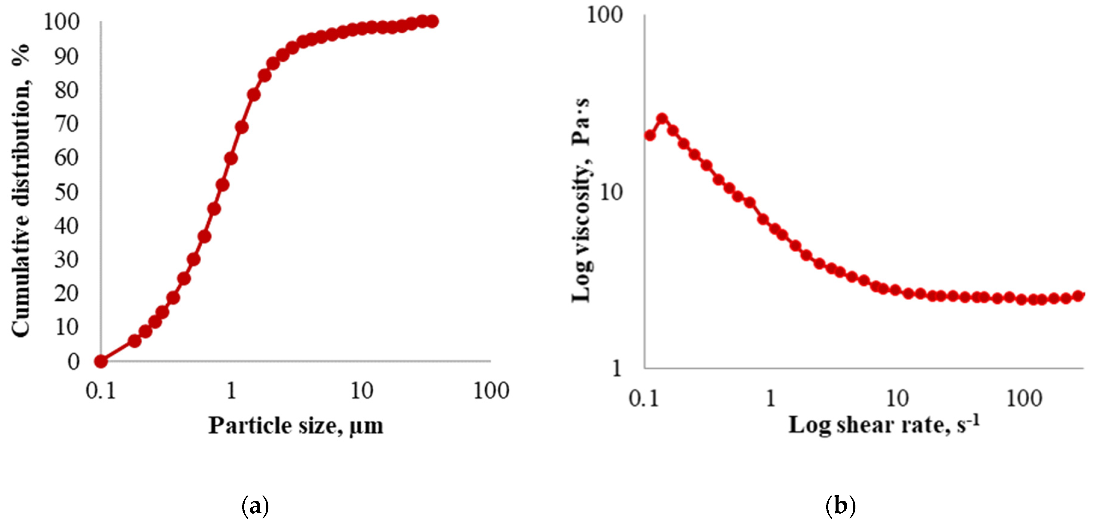
3.1. Slurry Characterisation

The particle size distribution of the dispersant pre-treated ceramic powder is shown in Figure 4a. The mean particle size (d50) was approximately 0.80 µm and 90% (d90) of the particles were smaller than approximately 2.31 µm. The rheology of the prepared slurry expressed by the logarithmic representation of the viscosity curve as a function of shear rate is shown in Figure 4b.
The viscosity of the prepared slurry decreases with increasing shear rate. The slurry displayed a relatively stable condition under the action of shearing force, and the viscosity of the slurry did not vary considerably from shear rates higher than 10 s−1. Admaflex 130 is specifically designed to print slurries with a broad viscosity range, where a tape-casting method with rotating foil is used to spread a fresh slurry layer. The recommended rheology of the suspension for Admaflex technology is a shear thinning behaviour with a dynamic viscosity below 10 Pa·s for shear rates from 10 to 300 s−1 [25]. Typical shear rates within the process are up to approximately 200 s−1 when using a doctor blade gap of 120 µm and a layer thickness of 25 µm. The viscosity of the prepared slurry was lower than that of the limit value for the Admaflex technology.

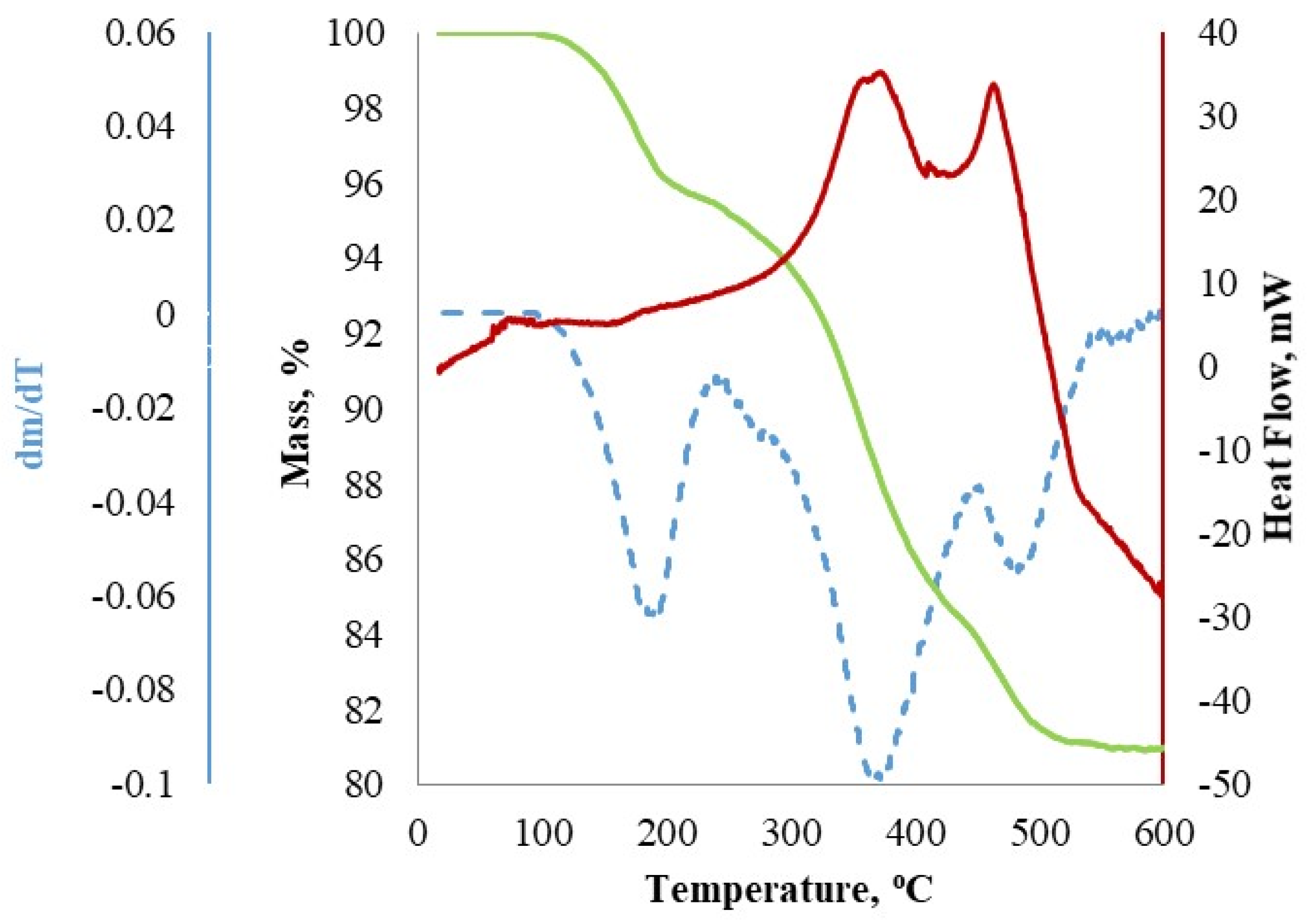
3.2. Thermal Debinding Analysis

The TGA-DSC analysis revealed information on the decomposition behaviour of the resin components with the temperature increase. To minimise delamination, cracking, deformation or collapse induced by thermal stress from polymer breakdown, the debinding process must be evaluated and the heating rate and dwell time adjusted accordingly [26]. The base resin consisted of a mixture of a mono-functional, di-functional, tetra-functional monomer and plasticiser. 4-acryloylmorpholine is widely used as a reactive monomer in photopolymerisable systems due to its low viscosity and good compatibility with acrylates and oligomers [27]. 1,6-hexanediol diacrylate is a low viscosity, di-functional acrylate ester monomer that is often employed as a reactive diluent in photopolymerisable slurry applications [28]. Pentaerythritol tetraacrylate is a tetra-functional monomer that is primarily used to aid in crosslinking for increased final modulus [29]. The function of the dibutyl phthalate as the plasticiser was to increase the flexibility of the part after curing [25].
From the TGA/DSC curve presented in Figure 5, it can be observed that the first mass loss of 3.6% begins to occur when the temperature is between 115 and 250 °C. This weight loss of 3.6% is assigned to the evaporation of the adsorbed water and residual cleaning solution. Within the temperature range and employed testing conditions, no peak was observed in the DSC curve [30]. The second rapid mass loss with a peak of 375.9 °C had a mass loss of 8.7%. The final mass loss occurs between 450 °C and 575 °C and is equal to 6.9%. Beyond 575 °C there is a negligible mass loss. According to the DTG curve, the extremum points of mass loss rate appear at 191.2 °C, 375.9 °C and 481.3 °C. The total mass loss is 19.2 wt%. Based on the composition of the prepared, uncured resin the total weight loss is slightly greater than expected, implying total burnout of the binding components. The excess weight loss might be attributed to adsorbed water during storage or the leftover dibasic ester. From the DSC curve, it can be concluded that the thermal debinding reaction is an exothermic process with two major peaks attributed to the oxidative decomposition of polymer chains (372.2 °C) and the thermal decomposition of the crosslinked polymer network (464.1 °C) [31]. The DSC curve also showed a weak peak at 70.8 °C, that may be a result of an artifact caused by the toppling over of the sample in the pan. According to the results of TGA and DSC curves, the parameters of the debinding process are determined. The temperature was first raised from room temperature to 190 °C and then kept for 2 h. After that, the temperature was raised to 375 °C and maintained for 4 h to allow enough time for the decomposition of the organic matter and reduce the effect of thermal stress on the sample. The next step was heating to 480 °C with a dwell time of 2 h. Finally, the temperature was continuously raised to 650 °C to ensure that the resin was completely removed, and then naturally cooled to room temperature. The whole debinding process took a total of 62.5 h without cooling.

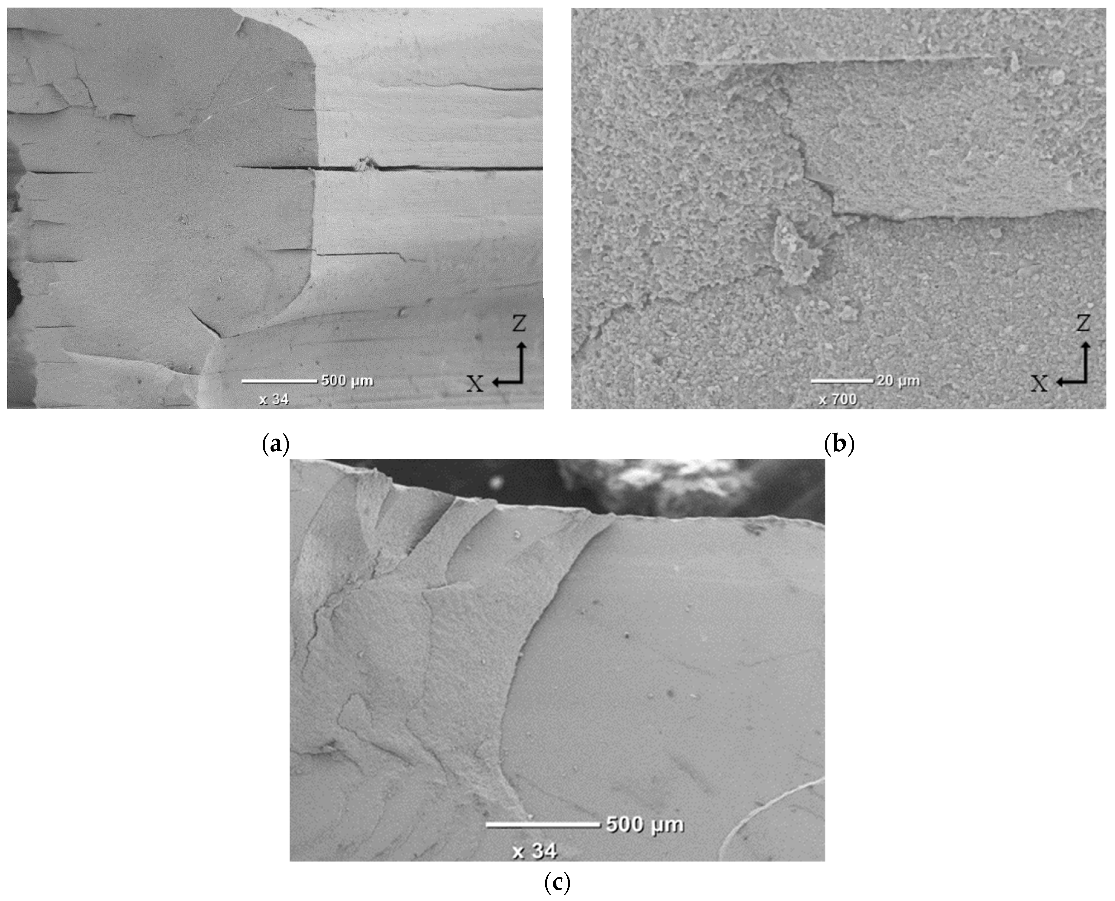
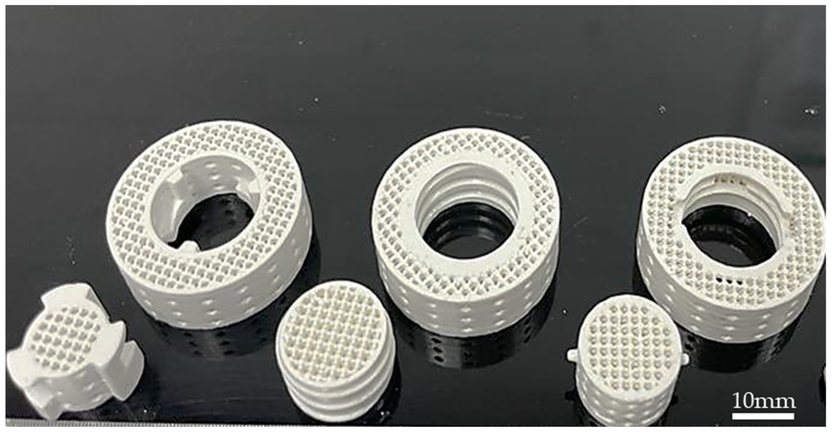
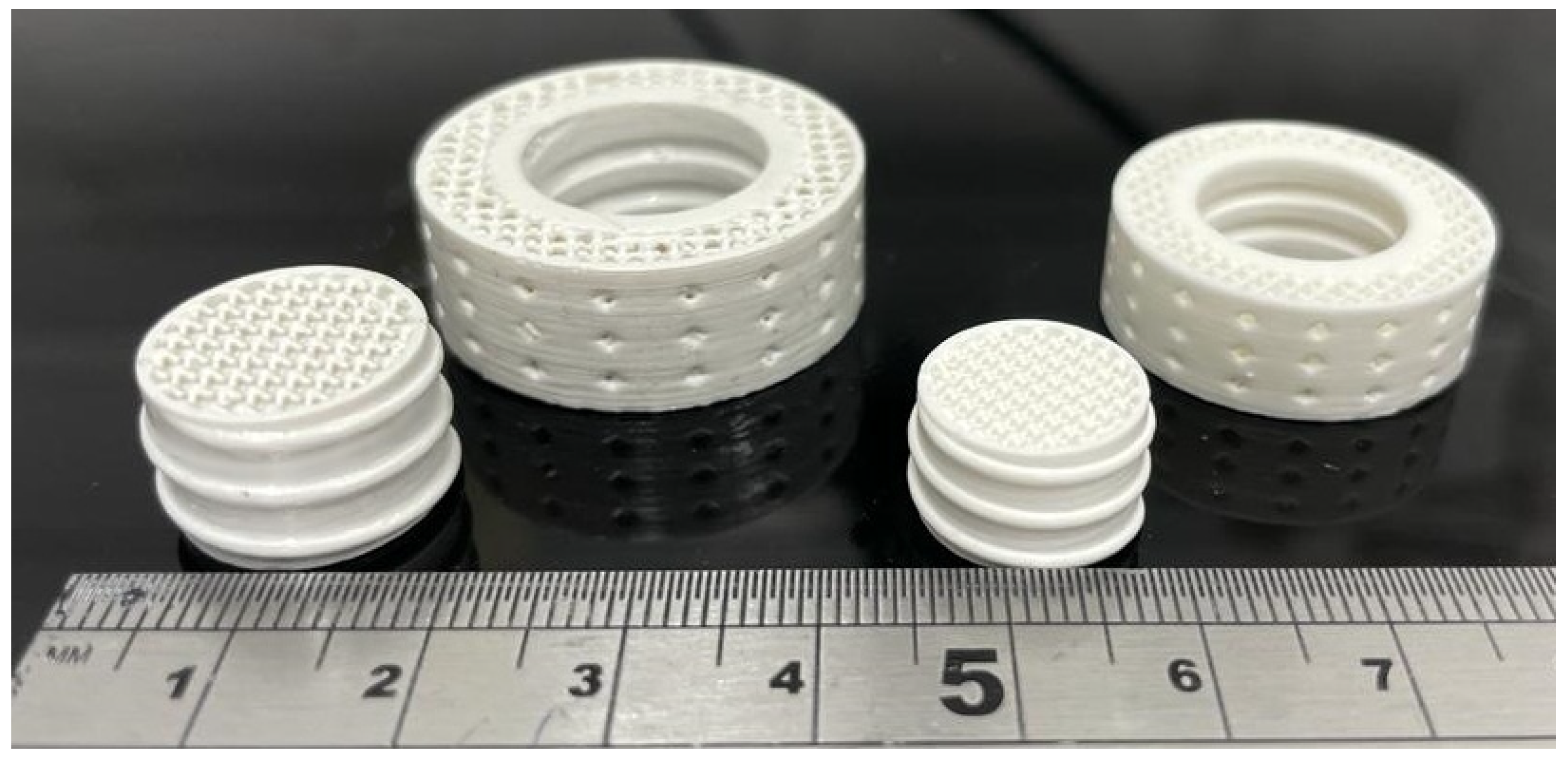
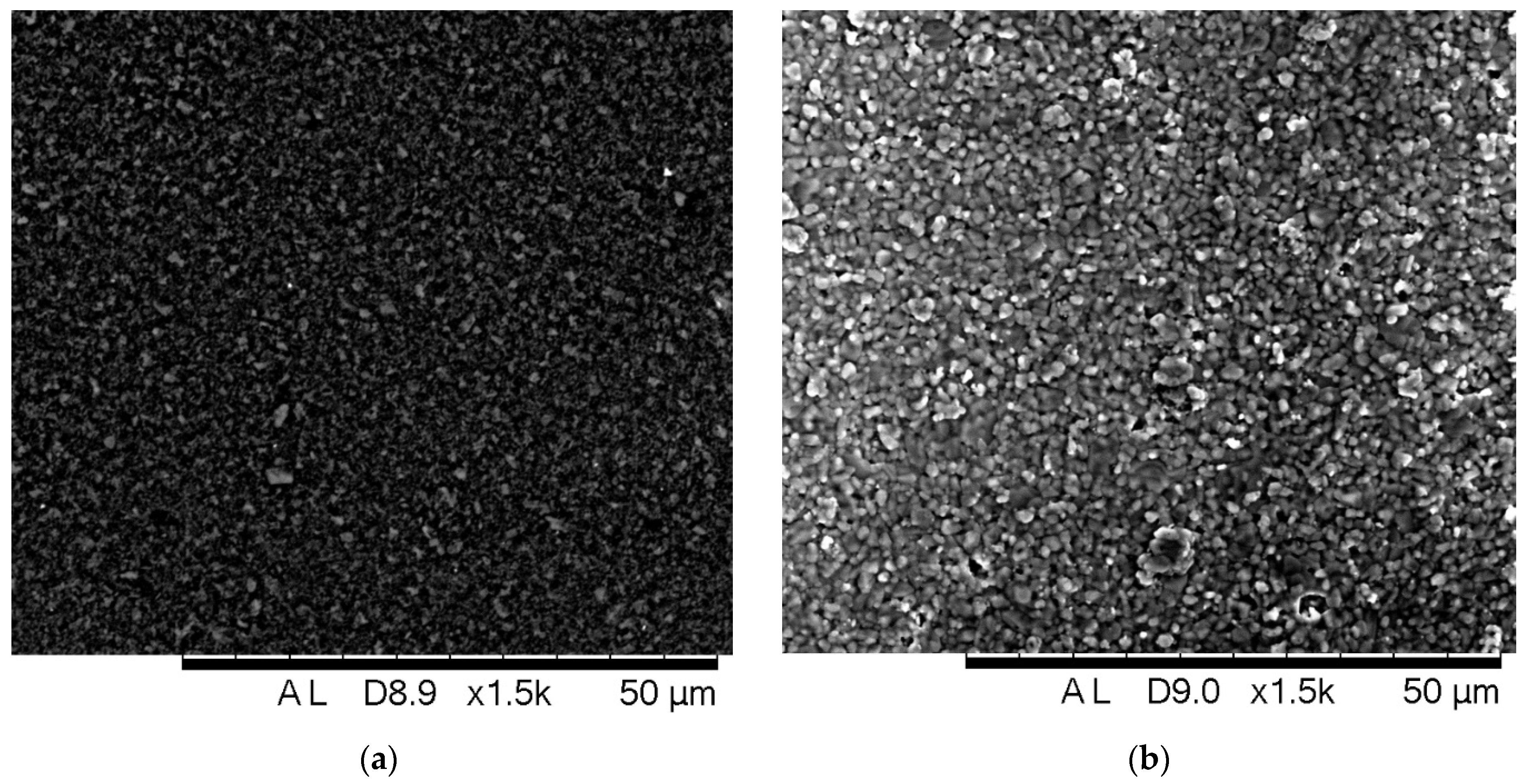
3.3. Characterisation of the Printed and Sintered Samples

The green parts are shown in Figure 6. The parts show sufficient quality after sacrificial layer removal and cleaning, no flaws were determined by visual inspection in the green stage and the green strength was high enough for handling. The layering effect is visible on the surface of the green and sintered parts, which was expected due to the employed additive layering process and over curing. According to the findings of our earlier work, the manufacturability of lattice structures is affected by the cure depth and the size of the exposure area of the sliced layer [22]. The struts of the lattices tend to be very fragile due to their small cross-sectional area, and it is not uncommon to experience complete breakage during the build.
As a result, for small exposure areas, larger cure depths were required to establish robust interlayer joints as well as to ensure a continuous build [22]. With the existing slurry formulation, over curing was inevitable. To reduce the layering effect, the literature suggests lowering the slice thickness or the cure time [32,33]. However, the latter can also reduce cure depth, while the thinner layers lead to a longer printing time, reducing printing efficiency. An example of green and sintered components is presented in Figure 7 to illustrate the differences in the part dimensions before and after the thermal post-processing stages.
As expected, the parts exhibited shrinkage upon firing at high temperatures. Shrinkages of X−Y and Z directions were approximately 14% and 19%, respectively, with a relatively high difference of 5% between the X–Y and Z directions. This anisotropic dimension shrinkage behaviour of the AM parts is related to the layered shaping process [27,34].
The anticipated shrinkage was compensated by increasing the starting CAD models by estimated shrinkage factors in X–Y (1.143) and Z (1.205). According to the experimental results, the actual shrinkage factors in the X–Y, and Z directions were determined to be 1.143 and 1.235, respectively, at the energy dose of 42 mJ/cm2. Nevertheless, the overall shrinkage of the parts was low due to the high solid phase loading (57 vol%) in the ceramic slurry. In view of the shrinkage of the actual size, specific values of the ceramic samples in the green stage and the as-sintered stage are shown in Table 2.
The CAD dimensions in the Z-direction listed in Table 2 correspond to the parts without the sacrificial layers. The green bodies were up to 3.26% larger than the CAD designs within the X–Y plane. The minor variations in the sample’s heights in the green parts are due to the extraction of the sacrificial layers.
Figure 8 illustrates the SEM images of the surface of the green and sintered parts: (a) shows an SEM image of the green body, in which it can be seen that particles are homogeneously distributed in the solidified polymeric resin; and (b) shows SEM image of the surface after sintering at 1540 °C, where small pores at the grain boundaries are seen, without complete densification.
As the complex features of the parts fabricated in this work may affect the results of density measurements, five cubes were manufactured, debinded and sintered together with the hybrid substrates. The mean density value was determined to be 97.88 ± 0.01%. The resulting density is acceptable for catalytic supports.
Achieving higher density would be beneficial for the mechanical strength of the substrates; however, it is not essential for application in catalytic substrates as the residual porosity is advantageous for the adhesion of the washcoat [35].

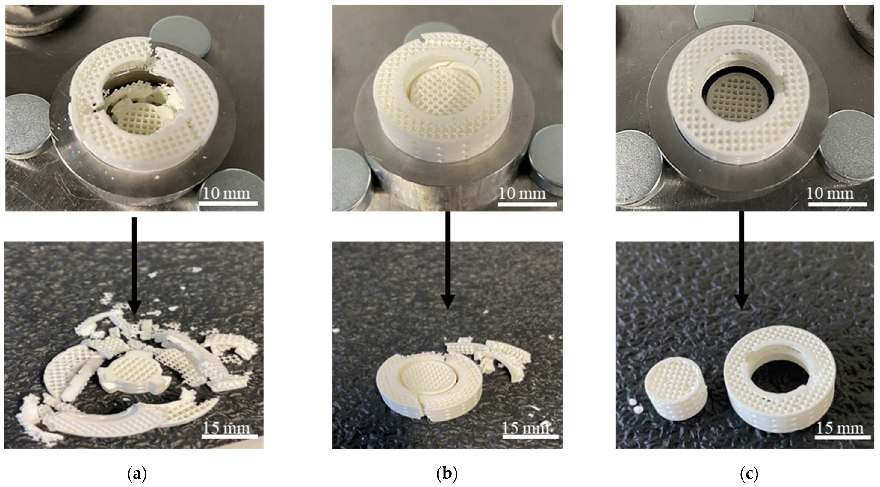
3.4. Mechanical Integrity

The results of the mechanical integrity test are presented in Figure 9. The deformation behaviour of the parts after the test is shown in Figure 10. The samples show similar trends in the force-displacement curves, with several major and minor peaks and finally a force plateau after reaching failure. With external load increasing, multiple peaks were found to appear in the curves of all interlock configurations in this study. At each peak load for the U-lock interlock, a crack formed in the outer shell. The outer shell of the U-lock mechanism experienced greater stresses than the core specimen that spread from the interlocking mechanism to the outer edges of the shell substrate resulting in cracks that run horizontally and perpendicularly as seen in Figure 10a.
The horizontal cracks are anticipated to be a result of the generation of stresses in the outer shell due to the vertical load acting on the core specimen pushing down on the L-shaped protrusions. The shell substrate lost its structural integrity and gradually crumbled and collapsed, leading to catastrophic failure with broken pieces of various shapes and sizes. The Thread topology force–displacement curve presents various peaks with a gradual decrease in the peak forces with the increase in displacement. The first major peak was lower than the highest peak which was attributed to the settling of the core inside of the shell substrate.
As the loading proceeded, the load started to re-direct in a diagonal manner which led to the diagonal fractures of the shell substrate. The major peaks could be attributed to the propagation of diagonal and horizontal cracks in the shell substrate (Figure 10b). The external thread on the core substrate was stronger than the internal thread of the shell substrate.
For the Twist-lock specimen, the force–displacement curve presents two force peaks associated with the snapping of the side pins from the surface of the cylindrical core substrate. This is due to the small area of the pins, which did not provide enough resistance to the applied force before failure. Once the pins snapped off, the force decreased and plateaued as the core slid out of the outer substrate leaving the interlocking system of the outer shell intact as seen in Figure 10c.
It can be observed that the shape of the force–displacement response is affected by the interlock topology. It is well known that ceramics are sensitive to flaws [17]. Minor flaws introduced during manufacturing and thermal post-processing of ceramic-printed components can significantly attenuate the strength and toughness of the final parts. SEM micrographs of fractured specimens are shown in Figure 11. Interlayer delamination is observed at a number of layer intervals (Figure 11a). The delamination originates from the “bottom-up” layer-by-layer fabrication process and the shrinkage that occurs during the heat treatment process. During loading, the delaminated regions act as stress concentrator and trigger crack propagation [36]. Hence, smaller cracks are seen in Figure 11b which emanate from the delaminated regions. Figure 11c shows a brittle fracture, characteristic of ceramic materials. Both the interlayer and intralayer surfaces are visible in the SEM image. Similar to other AM methods, the DLP manufacturing technique still presents challenges inherent to the layering technique and sintering processes of the printed parts which ultimately influence the mechanical strength of the part [37]. Layer bonding could be improved by systematic optimisation of the printing process parameters in conjunction with heating rate, dwell time and dwell temperatures of the debinding and sintering.
Employing an additive manufacturing approach for catalyst substrate production can yield improved versatility and allow fabrication of geometries and configurations that traditional manufacturing techniques cannot achieve. The design and manufacturing method employed in this study can be applied to integrate multiple catalytic systems into a single monolithic system. The application and function of the individual substrates in the hybrid concept are highly dependent on the particular application, engine operating procedures, exhaust conditions, etc. For example, the hybrid substrate concept can be applied to reduce the aftertreatment catalyst volume by employing it in advanced aftertreatment solutions, such as exhaust gas reforming, where the core substrate can be catalyst coated to provide reforming and the shell substrate can be coated to provide aftertreatment. The dimensional parameters of the individual substrates can also be altered, for example, to deliver small reformate/H2 concentrations to the aftertreatment system, a shorter reforming catalyst core can be fitted at the entrance of the longer shell aftertreatment catalyst. In this case, the lattice architecture would aid in directing the flow from the core catalyst to the shell catalyst and provide enhanced interaction of the gas flow with the washcoat. On the other hand, the hybrid substrate approach could be utilised to increase the efficiency of individual components of the aftertreatment, as in the work from Lefort et al. [3], where the core catalyst can provide good light-off performance and the shell substrate can be used to retain heat. In this case, the catalyst loading between the two substrates may be varied, or the substrate design can be modified to include alternative architecture, different strut/wall thickness and/or cell size.

4. Conclusions

This study demonstrated the possibility of AM of hybrid monolithic ceramic substrates that could be utilised as catalyst reactors for aftertreatment applications. A novel design approach and an additive manufacturing (AM) technique were proposed to manufacture dual-substrate monoliths. The DLP manufacturing process enabled the fabrication of highly complex parts with various interlocking mechanisms which could not be obtained by conventional processing techniques. Photoreactive alumina slurry with suitable rheological behaviour for the employed printer was used as the base material for the part manufacturing. The green parts were subjected to two thermal treatments—debinding and sintering. Analysis of the DSC/TGA and DTG curves revealed the debinding conditions. The layering effect was observed as inherent to the layer-by-layer manufacturing process and high energy dose and over five times higher cure depth than the layer thickness which caused over curing. The sintered parts displayed anisotropic shrinkage after sintering, with the shrinkage of approximately 14% in the X–Y direction and 19% in the Z direction. The sintered density was 97.88 ± 0.01%, acceptable for catalytic substrate applications. A mechanical testing campaign was performed to study the mechanical integrity of the interlocking configurations. The force–displacement response was found to be affected by the topology of the interlocks in the substrates. U-lock and Thread configurations were found to sustain more load until complete failure. Future work should focus on investigating the feasibility of the proposed integrated substrate in the aftertreatment applications.

Author Contributions

Methodology, formal analysis, writing—original draft preparation, investigation, data curation, visualization, and conceptualization, N.K.; writing—review and editing, K.E., S.L., W.L. and S.Z.-R.; supervision, A.T. and K.E. All authors have read and agreed to the published version of the manuscript.

Funding

This research was funded by Engineering and Physical Sciences Research Council for project FACE-Novel Integrated Fuel Reformer-Aftertreatment System for Clean and Efficient Road Vehicles under grant number EP/P03117X/1.

Data Availability Statement

All data are available within the article.

Acknowledgments

N.K. thanks the University of Birmingham for the award of a PhD scholarship.

Conflicts of Interest

The authors declare no conflict of interest.

References

  1. Baharudin, L.; Watson, M.J. Monolithic Substrate Support Catalyst Design Considerations for Steam Methane Reforming Operation. Rev. Chem. Eng. 2018, 34, 481–501. [Google Scholar] [CrossRef]
  2. Ayodhya, A.S.; Narayanappa, K.G. An Overview of After-Treatment Systems for Diesel Engines. Environ. Sci. Pollut. Res. 2018, 25, 35034–35047. [Google Scholar] [CrossRef] [PubMed]
  3. Lefort, I.; Tsolakis, A. A Thermally Efficient DOC Configuration to Improve CO and THC Conversion Efficiency. SAE Tech. Pap. 2013. [Google Scholar] [CrossRef]
  4. Hazlett, M.J.; Epling, W.S. Heterogeneous Catalyst Design: Zoned and Layered Catalysts in Diesel Vehicle Aftertreatment Monolith Reactors. Can. J. Chem. Eng. 2019, 97, 188–206. [Google Scholar] [CrossRef]
  5. Megaritis, A.; Wyszynski, M.L.; Tsolakis, A.; Cracknell, R.; Peucheret, S.M.; Xu, H.M.; Abu-Jrai, A.; Golunski, S.E.; Theinnoi, K. Exhaust Gas Fuel Reforming for IC Engines Using Diesel Type Fuels. SAE Tech. Pap. Ser. 2010, 1, 1289–1294. [Google Scholar] [CrossRef]
  6. Herreros, J.M.; Gill, S.S.; Lefort, I.; Tsolakis, A.; Millington, P.; Moss, E. Enhancing the Low Temperature Oxidation Performance over a Pt and a Pt-Pd Diesel Oxidation Catalyst. Appl. Catal. B Environ. 2014, 147, 835–841. [Google Scholar] [CrossRef] [Green Version]
  7. Umar, M.; Nozari, H.; Menezes, M.R.; Herreros, J.M.; Lau, C.S.; Tsolakis, A. Hydrogen Production from Bioethanol Fuel Mixtures via Exhaust Heat Recovery in Diesel Engines: A Promising Route towards More Energy Efficient Road Vehicles. Int. J. Hydrog. Energy 2021, 46, 23603–23614. [Google Scholar] [CrossRef]
  8. Azis, M.M.; Auvray, X.; Olsson, L.; Creaser, D. Evaluation of H2 Effect on NO Oxidation over a Diesel Oxidation Catalyst. Appl. Catal. B Environ. 2015, 179, 542–550. [Google Scholar] [CrossRef]
  9. Theinnoi, K.; Temwutthikun, W.; Wongchang, T.; Sawatmongkhon, B. Application of Exhaust Gas Fuel Reforming in Diesel Engines towards the Improvement Urban Air Qualities. Energy Procedia 2018, 152, 875–882. [Google Scholar] [CrossRef]
  10. Negri, M. Technology Development for ADN-Based Green Monopropellant Thrusters—An Overview of the Rheform Project. In Proceedings of the 7th European Conference for Aeronautics and Space Sciences, Milan, Italy, 3–6 July 2017; pp. 1–13. [Google Scholar]
  11. Koopmans, R.; Schuh, S.; Bartok, T.; Forschungs-, F.; Gmbh, T.; Kaplan-straße, V.; Neustadt, W.; Schwentenwein, M.; Spitzbart, M. Performance Comparison between Extruded and Printed Ceramic Monoliths for Catalysts. In Proceedings of the 7th European Conference for Aeronautic and Space Sciences (EUCASS), Milan, Italy, 3–6 July 2017; p. 2700. [Google Scholar]
  12. Essa, K.; Hassanin, H.; Attallah, M.M.; Adkins, N.J.; Musker, A.J.; Roberts, G.T.; Tenev, N.; Smith, M. Development and Testing of an Additively Manufactured Monolithic Catalyst Bed for HTP Thruster Applications. Appl. Catal. A Gen. 2017, 542, 125–135. [Google Scholar] [CrossRef] [Green Version]
  13. Hassanin, H.; Alkendi, Y.; Elsayed, M.; Essa, K.; Zweiri, Y. Controlling the Properties of Additively Manufactured Cellular Structures Using Machine Learning Approaches. Adv. Eng. Mater. 2020, 22, 1901338. [Google Scholar] [CrossRef]
  14. Hassanin, H.; El-Sayed, M.A.; Elshaer, A.; Essa, K.; Jiang, K. Microfabrication of Net Shape Zirconia/Alumina Nanocomposite Micro Parts. Nanomaterials 2018, 8, 593. [Google Scholar] [CrossRef] [PubMed] [Green Version]
  15. Sabouri, A.; Yetisen, A.K.; Sadigzade, R.; Hassanin, H.; Essa, K.; Butt, H. Three-Dimensional Microstructured Lattices for Oil Sensing. Energy Fuels 2017, 31, 2524–2529. [Google Scholar] [CrossRef] [Green Version]
  16. El-Sayed, M.A.; Essa, K.; Ghazy, M.; Hassanin, H. Design Optimization of Additively Manufactured Titanium Lattice Structures for Biomedical Implants. Int. J. Adv. Manuf. Technol. 2020, 110, 2257–2268. [Google Scholar] [CrossRef]
  17. Hassanin, H.; Essa, K.; Elshaer, A.; Imbaby, M.; El-Mongy, H.H.; El-Sayed, T.A. Micro-Fabrication of Ceramics: Additive Manufacturing and Conventional Technologies. J. Adv. Ceram. 2021, 10, 1–27. [Google Scholar] [CrossRef]
  18. Kovacev, N.; Li, S.; Zeraati-Rezaei, S.; Hemida, H.; Tsolakis, A.; Essa, K. Effects of the Internal Structures of Monolith Ceramic Substrates on Thermal and Hydraulic Properties: Additive Manufacturing, Numerical Modelling and Experimental Testing. Int. J. Adv. Manuf. Technol. 2020, 112, 1115–1132. [Google Scholar] [CrossRef]
  19. Papetti, V.; Eggenschwiler, P.D.; Della Torre, A.; Lucci, F.; Ortona, A.; Montenegro, G. Additive Manufactured Open Cell Polyhedral Structures as Substrates for Automotive Catalysts. Int. J. Heat Mass Transf. 2018, 126, 1035–1047. [Google Scholar] [CrossRef]
  20. Ferrizz, R.M.; Stuecker, J.N.; Cesarano, J.; Miller, J.E. Monolithic Supports with Unique Geometries and Enhanced Mass Transfer. Ind. Eng. Chem. Res. 2005, 44, 302–308. [Google Scholar] [CrossRef] [Green Version]
  21. Hajimirzaee, S.; Doyle, A.M. 3D Printed Catalytic Converters with Enhanced Activity for Low-Temperature Methane Oxidation in Dual-Fuel Engines. Fuel 2020, 274, 117848. [Google Scholar] [CrossRef]
  22. Kovacev, N.; Li, S.; Essa, K. Effect of the Preparation Techniques of Photopolymerizable Ceramic Slurry and Printing Parameters on the Accuracy of 3D Printed Lattice Structures. J. Eur. Ceram. Soc. 2021, 41, 7734–7743. [Google Scholar] [CrossRef]
  23. Schweiger, J.; Bomze, D.; Schwentenwein, M. 3D Printing of Zirconia–What Is the Future? Curr. Oral Health Rep. 2019, 6, 339–343. [Google Scholar] [CrossRef]
  24. Johansson, E.; Lidström, O.; Johansson, J.; Lyckfeldt, O.; Adolfsson, E. Influence of Resin Composition on the Defect Formation in Alumina Manufactured by Stereolithography. Materials 2017, 10, 138. [Google Scholar] [CrossRef] [PubMed] [Green Version]
  25. Gonzalez, P.; Schwarzer, E.; Scheithauer, U.; Kooijmans, N.; Moritz, T. Additive Manufacturing of Functionally Graded Ceramic Materials by Stereolithography. J. Vis. Exp. 2019, 2019, e57943. [Google Scholar] [CrossRef] [PubMed]
  26. Pfaffinger, M.; Mitteramskogler, G.; Gmeiner, R.; Stampfl, J. Thermal Debinding of Ceramic-Filled Photopolymers. Mater. Sci. Forum 2015, 825–826, 75–81. [Google Scholar] [CrossRef]
  27. Sun, J.; Binner, J.; Bai, J. Effect of Surface Treatment on the Dispersion of Nano Zirconia Particles in Non-Aqueous Suspensions for Stereolithography. J. Eur. Ceram. Soc. 2019, 39, 1660–1667. [Google Scholar] [CrossRef]
  28. Zakeri, S.; Vippola, M.; Levänen, E. A Comprehensive Review of the Photopolymerization of Ceramic Resins Used in Stereolithography. Addit. Manuf. 2020, 35, 101177. [Google Scholar] [CrossRef]
  29. He, R.; Liu, W.; Wu, Z.; An, D.; Huang, M.; Wu, H.; Jiang, Q.; Ji, X.; Wu, S.; Xie, Z. Fabrication of Complex-Shaped Zirconia Ceramic Parts via a DLP-Stereolithography-Based 3D Printing Method. Ceram. Int. 2018, 44, 3412–3416. [Google Scholar] [CrossRef]
  30. Borlaf, M.; Serra-Capdevila, A.; Colominas, C.; Graule, T. Development of UV-Curable ZrO2 Slurries for Additive Manufacturing (LCM-DLP) Technology. J. Eur. Ceram. Soc. 2019, 39, 3797–3803. [Google Scholar] [CrossRef]
  31. Wang, L.; Liu, X.; Wang, G.; Tang, W.; Li, S.; Duan, W.; Dou, R. Partially Stabilized Zirconia Moulds Fabricated by Stereolithographic Additive Manufacturing via Digital Light Processing. Mater. Sci. Eng. A 2020, 770, 138537. [Google Scholar] [CrossRef]
  32. Kowsari, K.; Zhang, B.; Panjwani, S.; Chen, Z.; Hingorani, H.; Akbari, S.; Fang, N.X.; Ge, Q. Photopolymer Formulation to Minimize Feature Size, Surface Roughness, and Stair-Stepping in Digital Light Processing-Based Three-Dimensional Printing. Addit. Manuf. 2018, 24, 627–638. [Google Scholar] [CrossRef]
  33. Li, X.; Zhong, H.; Zhang, J.; Duan, Y.; Bai, H.; Li, J.; Jiang, D. Dispersion and Properties of Zirconia Suspensions for Stereolithography. Int. J. Appl. Ceram. Technol. 2019, 17, 239–247. [Google Scholar] [CrossRef] [Green Version]
  34. De Camargo, I.L.; Erbereli, R.; Taylor, H.; Fortulan, C.A. 3Y-TZP DLP Additive Manufacturing: Solvent-Free Slurry Development and Characterization. Mater. Res. 2021, 24. [Google Scholar] [CrossRef]
  35. Santoliquido, O.; Bianchi, G.; Dimopoulos Eggenschwiler, P.; Ortona, A. Additive Manufacturing of Periodic Ceramic Substrates for Automotive Catalyst Supports. Int. J. Appl. Ceram. Technol. 2017, 14, 1164–1173. [Google Scholar] [CrossRef]
  36. Al-Ketan, O.; Pelanconi, M.; Ortona, A.; Abu Al-Rub, R.K. Additive Manufacturing of Architected Catalytic Ceramic Substrates Based on Triply Periodic Minimal Surfaces. J. Am. Ceram. Soc. 2019, 102, 6176–6193. [Google Scholar] [CrossRef]
  37. Osman, R.B.; van der Veen, A.J.; Huiberts, D.; Wismeijer, D.; Alharbi, N. 3D-Printing Zirconia Implants; a Dream or a Reality? An in-Vitro Study Evaluating the Dimensional Accuracy, Surface Topography and Mechanical Properties of Printed Zirconia Implant and Discs. J. Mech. Behav. Biomed. Mater. 2017, 75, 521–528. [Google Scholar] [CrossRef]
Figure 1. CAD models of the interlock designs, iso view of core and shell with cross-sectional shell view for (a) U-lock: core (A) and shell (A’); (b) Twist-lock: core (B) and shell (B’); (c) Thread: core (C) and shell (C’).
Aerospace 09 00255 g001
Figure 2. Chemical structure of the resin components: (a) 4-acryloylmorpholine; (b) 1,6-hexanediol diacrylate; (c) dibutyl phthalate; (d) pentaerythritol tetraacrylate.
Aerospace 09 00255 g002
Figure 3. Schematic of the Admaflex 130 printer.
Aerospace 09 00255 g003
Figure 4. (a) Particle size distribution of the dispersant-treated powder; (b) Viscosity of the prepared slurry.
Aerospace 09 00255 g004
Figure 5. DSC/TGA and DTG curves.
Aerospace 09 00255 g005
Figure 6. Green parts (from left to right: U-lock, Thread, Twist-lock).
Aerospace 09 00255 g006
Figure 7. Green parts (left) and sintered parts (right).
Aerospace 09 00255 g007
Figure 8. SEM images of the (a) green surface and the (b) sintered surface.
Aerospace 09 00255 g008
Figure 9. Force–displacement relationship for the interlocking mechanisms.
Aerospace 09 00255 g009
Figure 10. Deformation behaviour of (a) U-lock; (b) Thread; (c) Twist-lock.
Aerospace 09 00255 g010
Figure 11. SEM images of a fracture surface at (a) low magnification and (b) high magnification. The legend axis indicates build direction was in the vertical (Z) direction. (c) Top side of the fracture surface.
Aerospace 09 00255 g011
Table 1. Key parameters of the employed DLP printer.
TechnologyLayer Thickness, µmPrinting Build Volume (X,Y,Z), mmIndividual Pixel Size, µmWavelength, nm
DLP10–20096 × 54 × 11040405
Table 2. Dimensions of the green bodies, sintered bodies, and the sintering shrinkage.
CAD, mmGreen Body, mmSintered Body, mmSintering Shrinkage, %
PartX–YZX–YZX–YZX–YZ
A14.5310.7715.02 ± 0.1710.50 ± 0.2313.01 ± 0.098.52 ± 0.0613.3818.86
A’29.0310.7729.16 ± 0.2010.46 ± 0.1824.87 ± 0.078.40 ± 0.0214.7119.69
B14.5310.7714.78 ± 0.0810.46 ± 0.0212.78 ± 0.068.57 ± 0.2113.5218.07
B’29.0310.7729.08 ± 0.1410.44 ± 0.0424.81 ± 0.498.49 ± 0.1114.6818.68
C14.5310.7714.93 ± 0.2310.44 ± 0.1212.89 ± 0.108.50 ± 0.0613.6618.58
C’29.0310.7729.22 ± 0.1110.58 ± 0.1724.86 ± 0.078.58 ± 0.1214.9218.90
Publisher’s Note: MDPI stays neutral with regard to jurisdictional claims in published maps and institutional affiliations.

